EP2899697B1 - Coin dispensing apparatus - Google Patents
Coin dispensing apparatus Download PDFInfo
- Publication number
- EP2899697B1 EP2899697B1 EP14196107.8A EP14196107A EP2899697B1 EP 2899697 B1 EP2899697 B1 EP 2899697B1 EP 14196107 A EP14196107 A EP 14196107A EP 2899697 B1 EP2899697 B1 EP 2899697B1
- Authority
- EP
- European Patent Office
- Prior art keywords
- coin
- dispensing
- coins
- coin dispensing
- guide member
- Prior art date
- Legal status (The legal status is an assumption and is not a legal conclusion. Google has not performed a legal analysis and makes no representation as to the accuracy of the status listed.)
- Active
Links
Images


Classifications
-
- G—PHYSICS
- G07—CHECKING-DEVICES
- G07F—COIN-FREED OR LIKE APPARATUS
- G07F9/00—Details other than those peculiar to special kinds or types of apparatus
- G07F9/06—Coin boxes
-
- G—PHYSICS
- G07—CHECKING-DEVICES
- G07D—HANDLING OF COINS OR VALUABLE PAPERS, e.g. TESTING, SORTING BY DENOMINATIONS, COUNTING, DISPENSING, CHANGING OR DEPOSITING
- G07D1/00—Coin dispensers
-
- G—PHYSICS
- G07—CHECKING-DEVICES
- G07D—HANDLING OF COINS OR VALUABLE PAPERS, e.g. TESTING, SORTING BY DENOMINATIONS, COUNTING, DISPENSING, CHANGING OR DEPOSITING
- G07D3/00—Sorting a mixed bulk of coins into denominations
-
- G—PHYSICS
- G07—CHECKING-DEVICES
- G07D—HANDLING OF COINS OR VALUABLE PAPERS, e.g. TESTING, SORTING BY DENOMINATIONS, COUNTING, DISPENSING, CHANGING OR DEPOSITING
- G07D3/00—Sorting a mixed bulk of coins into denominations
- G07D3/12—Sorting coins by means of stepped deflectors
- G07D3/128—Rotary devices
-
- G—PHYSICS
- G07—CHECKING-DEVICES
- G07D—HANDLING OF COINS OR VALUABLE PAPERS, e.g. TESTING, SORTING BY DENOMINATIONS, COUNTING, DISPENSING, CHANGING OR DEPOSITING
- G07D9/00—Counting coins; Handling of coins not provided for in the other groups of this subclass
- G07D9/008—Feeding coins from bulk
-
- G—PHYSICS
- G07—CHECKING-DEVICES
- G07F—COIN-FREED OR LIKE APPARATUS
- G07F5/00—Coin-actuated mechanisms; Interlocks
- G07F5/20—Coin-actuated mechanisms; Interlocks specially adapted for registering coins as credit, e.g. mechanically actuated
Definitions
- the present invention relates to a coin dispensing apparatus and more particularly, to a coin dispensing apparatus configured by driving a plurality of coin dispensing units with a common or single driving device, in which each of the coin dispensing units is capable of dropping randomly-stored coins into respective apertures of a rotary disk one by one, and sending the coins thus dropped in the apertures toward the circumference of the disk one by one at a predetermined position.
- This prior-art coin processing apparatus comprises a coin receiving section for receiving and temporarily storing inputted coins of a plurality of denominations; a coin transporting section for separating the coins inputted into the coin receiving section from each other and transporting the coins thus separated along a coin passage; a coin discriminating section, provided at an inlet section of the coin passage, for discriminating true coins and false ones from the coins thus transported and the denominations of the true coins; a coin selecting section, provided at the bottom of the coin passage, for selecting the coins transported in the coin passage by dropping downward the coins at different positions according to the denominations; a coin storing section for storing the coins that have been selected by the coin selecting section for each denomination; a coin dispensing section, provided at the bottom of the coin storing section, for dispensing the coins stored in the coin storing section one by one; a coin dispensing driving section for driving the coin dispensing section; and a horizontal coin
- the coin dispensing driving section is provided to be apart from the coin dispensing section at a predetermined distance, a power transmission means for transmitting a driving power is provided between the coin dispensing driving section and the coin dispensing section, and the horizontal coin transporting section is located in a space formed between the coin dispensing driving section and the coin dispensing section.
- This prior-art coin dispensing apparatus comprises two coin hoppers, which are arranged laterally, for dispensing coins one by one by rotary disks; a common dispensing passage, which extends vertically between the coin hoppers, for guiding the coins dispensed from the coin hoppers; a common driving motor for rotating the disks; and a transmission device for selectively connecting the driving motor to one of the rotating disks.
- a safe apparatus configured to be detachably attached to a charging device such as an onboard ticket issuing system disclosed in JP2514825B published in 1996.
- This prior-art safe apparatus comprises a chamber for receiving sales coins such as 50 yen and 500 yen which are selected from inserted coins by users through a coin inlet of the charging device; two hoppers for storing prepared coins of two denominations such as 10 yen and 100 yen which are selected from the inserted coins per denomination, wherein slits are provided for discharging the prepared coins thus stored on one side of the bottom of each hopper; rotary plates supported by the bottom of each hopper to be rotatable along predetermined directions, wherein each plate has circular depressed coin saucers arranged at a predetermined pitch circumferentially and wherein each coin saucer has a gap formed in such a way as to be matched to a corresponding one of the slits whenever the coins saucer is rotated by a predetermined angle; and
- a coin dispensing apparatus disclosed in EP 2 830 025 A1 which prevents excessive dispensing of coins without abruptly stopping a rotary disk.
- a movable guide member is provided in a carrying path of coins to be selectively located at a guiding position where the coins are guided toward a dispensing opening or a non-guiding position where the coins are not guided toward the dispensing opening.
- a movable stopper is provided in a dispensing passage communicating with the carrying path to be selectively located at a blocking position where the coins are blocked or a non-blocking position where the coins are not blocked to pass through the dispensing passage.
- the guide member is located at the guiding position and the stopper is located at the non-blocking position.
- the guide member is located at the non-guiding position and the stopper is located at the blocking position.
- the coin dispensing section comprises coin dispensing circular plates having coin dispensing holes.
- the coin dispensing plates are respectively rotated in the forward directions by individual driving motors by way of the power transmitting means.
- the coins are dropped in the coin dispensing holes by the forward rotation of the plates and separated from each other, thereby dispensing a predetermined number of the coins of the predetermined denominations.
- the coin hoppers for dispensing the coins are provided for the respective denominations.
- the rotary disks of these coin hoppers are rotated in the forward direction by the common driving motor to thereby drop the coins in the penetrating holes of the disks. In this way, the coins are separated from each other and a predetermined number of the coins of the predetermined denominations are dispensed.
- the rotation of the common driving motor is transmitted to the rotary disks by way of clutches, and the disk of the coin hopper corresponding to a predetermined denomination is selectively rotated in the forward direction.
- a predetermined number of the coins of the predetermined denominations are dispensed by switching the clutches.
- the coins of one denomination is dispensed and thereafter, the next coin dispensing process is carried out. In this way, the coin dispensing operations for the plurality of denominations are performed in series.
- the rotary plates are arranged at the bottoms of the cylindrical hoppers, and the coins are separated and dispensed one by one by the rotation of these plates.
- Two of the safe apparatuses are combined to form a pair.
- Bevel gear are fixed to the common rotational shaft to be rotated by the driving motor are respectively meshed or engaged with bevel gears connected to the plates.
- the plates are configured to be rotated by the rotation of the rotational shaft by way of the bevel gears.
- a one-way clutch is provided between the rotational shaft and one of the bevel gears.
- the count of the rotary disks that can be driven by a single driving motor is two and therefore, two driving motors are required for dispensing the coins of four denominations. This means that there is a problem that decreasing the mounting capacity or volume necessary for the safe apparatus is not easy and reducing the fabrication cost thereof is limited.
- the present invention was created to solve the aforementioned problems of the first to third prior-art apparatuses.
- a chief object of the present invention is to provide a coin dispensing apparatus capable of dispensing coins of a plurality of denominations surely and more quickly compared with the aforementioned prior-art apparatuses and capable of being fabricated at a low cost.
- Another object of the present invention is to provide a coin dispensing apparatus that is easy to be downsized.
- Still another object of the present invention is to provide a coin dispensing apparatus that is easy to do inspection and maintenance activities.
- a coin dispensing apparatus which comprises:
- the passage blocking member is provided in the dispensing opening of each of the coin dispensing units in such a way as to be selectively positioned at the non-blocking position or the blocking position while simultaneously rotating the disks of the coin dispensing units.
- the passage blocking member of the corresponding coin dispensing unit is positioned at the non-blocking position, allowing the coins to pass through the dispensing passage.
- the passage blocking member of the corresponding unit is positioned at the blocking position, preventing the coins from passing through the dispensing opening.
- the rotary disks of the coin dispensing units are simultaneously rotated or stopped by the common driving device by way of the transmission device, the rotation of the disks are kept until the coins are completely dispensed by the coin dispensing units. This means that the dispensing operations of the coins in the respective units are carried out in parallel.
- the dispensing operations of the coin dispensing units can be completed within a shorter time than the case where the dispensing operations of the coin dispensing units are carried out in series.
- the fabrication cost of the coin dispensing apparatus can be lowered.
- the coin dispensing apparatus is capable of dispensing the coins of a plurality of denominations surely and more quickly compared with the aforementioned prior-art apparatuses and capable of being fabricated at a low cost.
- the rotary disks of the coin dispensing units are driven by the common driving device by way of the transmission device. Therefore, the coin dispensing apparatus according to the first aspect of the present invention is easy to be downsized.
- the apertures of the rotary disks of the coin dispensing units have a same count and a same angular position.
- the relative positions of the coins placed in the apertures of the respective coin dispensing units will be the same when the disks are stopped.
- all the coins of the respective units can be positioned stably as desired. This means that all the disks can be prevented from being placed at subtle positions where it is subtle to judge whether or not the coin is ejected from the dispensing opening.
- the coin dispensing units are adjacently arranged along an arrangement line; the transmission device is placed along the arrangement line; and the transmission device comprises a common driving shaft rotated by the driving device, driving bevel gears fixed to the common driving shaft, and driven bevel gears which are respectively engaged with the driving bevel gears and which are respectively connected to the rotary disks of the coin dispensing units.
- the size of the combination of these units and the transmission device can be made small.
- the rotary disks of the coin dispensing units are respectively rotated by engagement between the driving bevel gears fixed to the common driving shaft and the driven bevel gears respectively connected to the rotary disks.
- the driving and driven bevel gears can be made small in diameter. Accordingly, there is an additional advantage that the coin dispensing apparatus can be downsized furthermore.
- the coin dispensing units are adjacently arranged along an arrangement line; the transmission device is placed along the arrangement line; and the transmission device comprises a common driving shaft rotated by the driving device, driving spiral bevel gears fixed to the common driving shaft, and driven spiral bevel gears which are respectively engaged with the spiral driving bevel gears and which are respectively connected to the rotary disks of the coin dispensing units. Since the coin dispensing units are adjacently arranged along the arrangement line and the transmission device is placed along the arrangement line, the size of the combination of these units and the transmission device can be made small.
- the rotary disks of the coin dispensing units are respectively rotated by engagement between the driving spiral bevel gears fixed to the common driving shaft and the driven spiral bevel gears respectively connected to the rotary disks.
- the driving and driven spiral bevel gears can be made smaller in diameter and less in noise level than the case where ordinary bevel gears are used. Accordingly, there is an additional advantage that the coin dispensing apparatus can be downsized furthermore and the noise level can be restrained.
- the transmitting device comprises a driving spur gear rotated by the driving device, and driven spur gears respectively connected to the rotary disks of the coin dispensing units; wherein the driving spur gear is engaged with an adjacent one of the driven spur gears by way of an idler gear, and wherein the driven spur gears are engaged with each other by way of an idler gear or gears. Since the driving spur gear and the driven spur gears, which are popular products and inexpensive, are used for rotating the rotary disks, there is an additional advantage that the fabrication cost of the coin dispensing apparatus is lowered furthermore.
- another coin dispensing apparatus which comprises:
- the passage blocking member is provided in the dispensing opening of each of the coin dispensing units in such a way that when the guide member is located at the guiding position, the passage blocking member is positioned at the non-blocking position, and when the guide member is located at the non-guiding position, the passage blocking member is positioned at the blocking position, while simultaneously rotating the disks of the coin dispensing units.
- the passage blocking member of the corresponding coin dispensing unit is positioned at the non-blocking position when the guide member is located at the guiding position, allowing the coins to pass through the dispensing passage.
- the passage blocking member of the corresponding unit is positioned at the blocking position when the guide member is located at the non-guiding position, preventing the coins from passing through the dispensing opening.
- the rotary disks of the coin dispensing units are simultaneously rotated or stopped by the common driving device by way of the transmission device, the rotation of the disks are kept until the coins are completely dispensed by the coin dispensing units. This means that the dispensing operations of the coins in the respective units are carried out in parallel.
- the dispensing operations of the coin dispensing units can be completed within a shorter time than the case where the dispensing operations of the coin dispensing units are carried out in series.
- the fabrication cost of the coin dispensing apparatus can be lowered.
- the coin dispensing apparatus is capable of dispensing the coins of a plurality of denominations surely and more quickly compared with the aforementioned prior-art apparatuses and capable of being fabricated at a low cost.
- the rotary disks of the coin dispensing units are driven by the common driving device by way of the transmission device. Therefore, the coin dispensing apparatus is easy to be downsized.
- the apertures of the rotary disks of the coin dispensing units have a same count and a same angular position. Since the apertures of the rotary disks of the coin dispensing units have a same count and a same angular position, the relative positions of the coins placed in the apertures of the respective coin dispensing units will be the same when the disks are stopped. Thus, by stopping the respective disks at a single phase, in other words, by stopping the rotation of an output shaft of the driving device at a single phase, all the coins of the respective units can be positioned stably as desired.
- a control circuit is further provided, wherein under control of the control circuit, the guide member is located at the guiding position and the passage blocking member is located at the non-blocking position and thereafter, the disk is started to be rotated, dispensing the coins; and wherein the guide member is moved to the non-guiding position and the passage blocking member is moved to the blocking position while simultaneously the rotating the disks, thereby stopping dispensing of the coins.
- the guide member is located at the guiding position and the passage blocking member is located at the non-blocking position while simultaneously rotating the rotary disks of the coin dispensing units.
- the coin dispensing operation is surely performed.
- the guide member is moved to the non-guiding position and the passage blocking member is moved to the blocking position while simultaneously rotating the disks of the units.
- the coins are not guided toward the dispensing opening. If by any chance the coins are reached the dispensing opening, the coins are blocked by the passage blocking member located at the blocking position, which means that the dispensing of the coins is surely prevented.
- a rotary encoder for detecting an angular position of the disk is further provided, wherein based on an angular position signal from the rotary encoder, rotation of the disk is stopped such that the coins moved along the carrying path are not overlaid on the blocking position of the passage blocking member.
- still another coin dispensing apparatus which comprises:
- the passage blocking member formed in the dispensing opening of each of the coin dispensing units is operated in such a way that when the guide member is located at the guiding position, the passage blocking member is positioned at the non-blocking position, and when the guide member is located at the non-guiding position, the passage blocking member is positioned at the blocking position, while simultaneously rotating the disks of the coin dispensing units.
- the passage blocking member of the corresponding coin dispensing unit is positioned at the non-blocking position and the guide member is located at the guiding position due to the operation of the interlocking device, allowing the coins to pass through the dispensing passage.
- the passage blocking member of the corresponding unit is positioned at the blocking position and the guide member is located at the non-guiding position due to the operation of the interlocking device, preventing the coins from passing through the dispensing opening.
- the rotary disks of the coin dispensing units are simultaneously rotated or stopped by the common driving device by way of the transmission device, the rotation of the disks are kept until the coins are completely dispensed by the coin dispensing units. This means that the dispensing operations of the coins in the respective units are carried out in parallel.
- the dispensing operations of the coin dispensing units can be completed within a shorter time than the case where the dispensing operations of the coin dispensing units are carried out in series.
- the fabrication cost of the coin dispensing apparatus can be lowered.
- the coin dispensing apparatus is capable of dispensing the coins of a plurality of denominations surely and more quickly compared with the aforementioned prior-art apparatuses and capable of being fabricated at a low cost.
- the rotary disks of the coin dispensing units are driven by the common driving device by way of the transmission device. Therefore, the coin dispensing apparatus is easy to be downsized.
- the interlocking device comprises a mechanical liking mechanism.
- the mechanical linking mechanism is used for the interlocking device and thus, the interlocking device can be formed smaller in size at a lower cost than the case where an electrical linking mechanism is used. Therefore, there is an additional advantage that the fabrication cost of the coin dispensing apparatus can be lowered furthermore.
- the interlocking device comprises an electrical actuator.
- the passage blocking member comprises a bar-shaped member which is protruded into the carrying path at the blocking position and retracted from the carrying path at the non-blocking position; and the guide member comprises a bar-shaped member which is movably supported by a shaft and which is moved by an actuator between the guiding position and the non-guiding position.
- a position selector for selectively positioning the guide member between the guiding position and the non-guiding position is further provided, wherein the position selector is rockably supported by a shaft and is rocked around the shaft by an actuator between a dispensing assisting position and a dispensing assisting position; and wherein when the position selector is located at the dispensing assisting position, the guide member is located at the guiding position, and when the position selector is located at the non-dispensing assisting position, the guide member is positioned at the non-guiding position.
- a control circuit is further provided, wherein under control of the control circuit, the guide member is located at the guiding position and the passage blocking member is located at the non-blocking position and thereafter, the disk is started to be rotated, dispensing the coins; and wherein the guide member is moved to the non-guiding position and the passage blocking member is moved to the blocking position while simultaneously the rotating the disks, thereby stopping dispensing of the coins.
- the guide member is located at the guiding position and the passage blocking member is located at the non-blocking position while simultaneously rotating the rotary disks of the coin dispensing units.
- the coin dispensing operation is surely performed.
- the guide member is moved to the non-guiding position and the passage blocking member is moved to the blocking position while simultaneously rotating the disks of the units.
- the coins are not guided toward the dispensing opening. If by any chance the coins are reached the dispensing opening, the coins are blocked by the passage blocking member located at the blocking position, which means that the dispensing of the coins is surely prevented.
- a rotary encoder for detecting an angular position of the disk is further provided, wherein based on an angular position signal from the rotary encoder, rotation of the disk is stopped such that the coins moved along the carrying path are not overlaid on the blocking position of the passage blocking member.
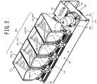
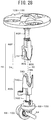
- a coin dispensing apparatus 10 according to the first embodiment of the present invention is shown in Figs. 1 to 3 .
- This apparatus 10 is incorporated into a payment system 14 which receives a dispensing instruction of change from an upper system, e.g., a POS system, and then, dispenses a predetermined number of coins of predetermined denominations to a reception tray 12 in response to the dispensing instruction.
- An example of the payment system 14 is a change machine.
- the coin dispensing apparatus 10 comprises four coin dispensing units 22 for different denominations of coins, which are laterally aligned on one side of a conveying belt 16 along a straight line. In other words, these four coin dispensing units 22 are arranged near the conveying belt 16 along the conveying direction of the same belt 16.
- each of the four units 22 dispenses an instructed number of coins of the predetermined denomination which is chosen from Japanese 10 yen coins 10C, Japanese 50 yen coin 50C, Japanese 100 yen coin 100C, and Japanese 500 yen coin 500C onto the belt 16 as change.
- the belt 16 conveys the coins thus dispensed as change to the reception tray 12.
- the coin dispensing apparatus 10 is not limited to four denominations but is applicable to two or more denominations.
- the coin dispensing apparatuses 10 are respectively placed at two sides of the conveying belt 16, this combination may be used for a change machine for Euro coins of eight denominations.
- the coin dispensing apparatus 10 may be used for United States coins, Australian coins, Chinese coins and so on, in addition to Japanese and Euro coins. Thus, this apparatus 10 is applicable to any coins used in the world.
- the coin dispensing apparatus 10 is driven by a common driving device 20 and has a function of dispensing a designated number of coins from the four coin dispensing units 22 prepared for the respective denominations.
- the apparatus 10 comprises the driving device 20, the coin dispensing unit 22-10 for the 10 yen coins, the coin dispensing unit 22-100 for the 100 yen coins, the coin dispensing unit 22-50 for the 50 yen coins, and the coin dispensing unit 22-500 for the 500 yen coins, a chassis 24, and a transmission device 26.
- the driving device 20 has a function of supplying necessary driving forces to the four coin dispensing units 22 provided for the predetermined denominations by way of the transmission device 26, thereby activating the functions of the units 22, as shown in Fig. 2 .
- the driving device 20 comprises an electric motor 28 and a speed reducer 30.
- the speed reducer 30 is not essential for the apparatus 10 and may be omitted.
- the electric motor 28 has a function of driving the four coin dispensing units 22 provided for the respective denominations.
- a known direct current (dc) motor is used as the motor 28. This is because a dc motor is small-sized and inexpensive and because forward and reverse rotations can be realized with a simple device.
- the present invention is not limited to a dc motor, but an alternative current (ac) motor, a pulse motor, an ultrasonic motor or the like may be used for this purpose.
- the speed reducer 30 has a function of reducing the rotation speed of the output shaft of the electric motor 28 to a prescribed rotation speed, thereby rotating the reducer output shaft 32.
- a known speed reducer may be used as the speed reducer 30.
- the chassis 24 has a function of supporting at least the electric motor 28, the four coin dispensing units 22, and the transmission device 26.
- the chassis 24 has a trapezoidal side view the upper surface 34 of which is inclined upward to the front of the apparatus 10, i.e., the side of the coin outlets 48 (48-10, 48-100, 48-50 and 48-500) of the coin dispensing units 22 (22-10, 22-100, 22-50 and 22-500). Therefore, the front end edge of the chassis 24 is higher than the rear end edge thereof.
- the four coin dispensing units 22 which will be explained later are arranged to be adjacent to each other along the longitudinal axis of the chassis 24.
- a plate-shaped intermediate base 36 is placed below the upper surface 34 of the chassis 24 so as to be parallel to the surface 34.
- the electric motor 28 is fixed to the intermediate base 36 by way of the speed reducer 30, where the output shaft (not shown) of the motor 28 is directed obliquely downward.
- the speed reducer 30 is fixed to the intermediate base 36, and the electric motor 28 is fixed to the speed reducer 30.
- the rotation of the output shaft of the electric motor 28 is reduced by the speed reducer 30 to be outputted as the rotation of the output shaft 32 of the reducer 30, where the output shaft 32 is directed downward.
- the top end of the output shaft 32 penetrates through the hole (not shown) of the intermediate base 36 to reach the rear side of the base 36.
- the transmission device 26 which is provided on the rear side of the intermediate base 36, has a function of transmitting the rotation of the driving device 20 to the respective coin dispensing units 22.
- the transmission device 26 comprises a driving gear 38, four idler gears 40, and four driven gears 42.
- the driven gears 42 are respectively provided for the four coin dispensing units 22.
- the driving gear 38 is a spur gear having a predetermined diameter and is fixed to the output shaft 32 of the speed reducer 30 on the rear side of the intermediate base 36.
- the driving gear 38 may be termed a driving spur gear 38S below.
- the idler gears 40 (40-10, 40-100, 40-50, 40-500) are rotatably attached to corresponding idler shafts 44 (44-10, 44-100, 44-50, 44-500) which are provided on the rear side of the intermediate base 36 so as to be directed downward.
- the idler gear 40 located at the closest position to the driving gear 38 (the driving spur gear 38S) is meshed with the driving gear 38.
- These four idler gears 40 are formed by spur gears having smaller diameters than that of the driving gear 38, thereby decreasing the overall size of the coin dispensing apparatus 10.
- the driven gears 42 (42-10, 42-100, 42-50, 42-500) are formed by spur gears and are respectively fixed to the lower ends of the corresponding input shafts 46 (46-10, 46-100, 46-50, 46-500) of the coin dispensing units 22 (22-10, 22-100, 22-50, 22-500).
- the driven gear 42 may be termed a driven spur gears 42S below.
- the driven gears 42 are meshed with the corresponding idler gears 40.
- the driven gear 42-500 is meshed with the idler gears 40-500 and 40-50
- the driven gear 42-50 is meshed with the idler gears 40-50 and 40-100
- the driven gear 42-100 is meshed with the idler gears 40-100 and 40-10
- the driven gear 42-10 is meshed with the idler gear 40-10.
- the driving spur gear 38S and the driven spur gears 42S have the same structure, in other words, they have the same pitch circle and the same tooth number.
- the rotation of the output shaft of the electric motor 28 is reduced by the speed reducer 30 at a predetermined ratio to thereby rotate the output shaft 32 of the reducer 30 at a predetermined rate and therefore, the driving spur gear 38S fixed to the shaft 32 is also rotated at a predetermined rate.
- the driving spur gear 38S rotates all the driven spur gears 42S by way of the idler gears 40 in the same direction at the same rate.
- the four combinations of the idler gear 40 and the driven gear 42 are provided in accordance with the number of the coin dispensing units 22.
- the driving spur gear 38S and the driven spur gears 42S have the same structure.
- the idler gears 40 are meshed with the adjoining driven gears 42.
- all the driven gears 42 are rotated in the same direction at the same speed as those of the driving gear 38.
- Each of the coin dispensing units 22 has a function of separating coins C that have been randomly collected and dispensing the coins C thus separated one by one. Since 10 yen coins 10C, 100 yen coins 100C, 50 yen coins 50C, and 500 yen coins 500C are used as change, the four coin dispensing units 22 (22-10, 22-100, 22-50, 22-500) are provided for these four denominations. These units 22 have the same structure except for the parts relating to the size difference among these four types of the coins 10C, 100C, 50C and 500C. As shown in Fig.
- the coin dispensing units 22-10, 22-100, 22-50 and 22-500 which are respectively provided for 10 yen coins 10C, 100 yen coins 100C, 50 yen coins 50C, and 500 yen coins 500C, are arranged in series and fixed onto the upper surface 34 of the chassis 24.
- the orientations of these units 22-10, 22-100, 22-50 and 22-500 are determined in such a way that the coin dispensing/ejecting directions are the same.
- the coin dispensing units 22 have almost the same structure, the structure of the unit 22-100 for 100 yen coins 100C will be explained on behalf of these four units 22 below.
- a hyphen and "100" as the denomination of 100 yen coins 100C should be attached to the reference numerals, e.g., 108-100; however, they are omitted here for the sake of simplification.
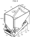
- the coin dispensing unit 22 (22-100) for 100 yen coins 100C comprises a frame 102, a base 104, a coin storing bowl or coin container 106, a rotary disk 108, a dispensing opening 110, a guide pin or guide member 112, a dispensing passage 114, an ejecting device 116, a coin sensor 118, a stopper or passage blocking member 120, and a control circuit 122.
- the frame 102, the base 104, the coin storing bowl 106, the rotary disk 108, the dispensing opening 110, the dispensing passage 114, and the coin sensor 118 have known structures, respectively.
- the feature of the coin dispensing unit 22 in this first embodiment relates to the guide pin or guide member 112 and the stopper or passage blocking member 120. However, it is essential for the present invention to include at least the stopper or passage blocking member 120. This is because the guide pin or guide member 112 can be omitted if the rotary disk 108 has a sufficiently large diameter.
- the base 104 (and the frame 102) may be termed the "body", because the rotary disk 108 is rotatably installed on the base 104, and various driving/controlling devices and members for the disk 108 (which will be described later) are mounted on the base 104.
- the body may comprise the frame 102 in addition to the base 104.
- the coin storing bowl or coin container 106 serves as a coin source for supplying the coins to the disk 108, it may be termed a "coin source”.
- the frame 102 has the structure on which the predetermined functional parts such as the base 104, the coin storing bowl 106, and the control circuit 122 can be attached or formed.
- the frame 102 is formed by a synthetic resin and comprises the shape like a hollow triangular pillar whose top end face is opened. The top end opening of the frame 102 is covered with the base 104.
- the input shaft 46 (46-100) is rotatably supported by the base 104 in such a way as to be located in the middle part of the base 104. (See Fig. 3 .)
- the input shaft 46 is almost perpendicularly protruded to the upper side of the base 104 through a circular through hole 124 which is located at the center of a circular disk receiving hole 126 (see Figs. 6 and 7 ).
- the lower end of the input shaft 46 is reached to the lower side of the intermediate base 36 by way of a through hole (not shown) formed on the intermediate base 36.
- the driven spur gear 42 (42-100) is fixed to the lower end of the input shaft 46 (46-100) at a position below the intermediate base 36.
- the base 104 is located to be inclined upward to the front end thereof (i.e., toward the dispensing opening 110). However, the base 104 may be inclined downward to the front end thereof and may be located horizontally.
- the dispensing opening 110 may be positioned on the upper or lower side of the inclined part of the base 104.
- the base 104 may be placed horizontally, in other words, may be placed parallel to the horizontal plane.
- the base 104 has a shape of a rectangular plate with a predetermined thickness.
- the disk receiving hole 126 is formed on the upper surface of the base 104.
- the base 104 has a function of holding the coin storing bowl or coin container 106 and a function of fixing the coin dispensing unit 22 onto the upper surface 34 of the chassis 24.
- the disk receiving hole 126 is defined by a circular plate-shaped bottom face 128 and an annular coin guiding wall 130 extending along the periphery of the bottom face 128. In other words, the disk receiving hole 126 is formed by the combination of the bottom face 128 and the coin guiding wall 130.
- the disk receiving hole 126 has the shape of a circular pan in which the rotary disk 106 is placed rotatably.
- the depth of the disk receiving hole 126 is set to be slightly larger than the thickness of the rotary disk 108, and the bottom face 128 is formed to be approximately flat in such a way that the coin C is slid on the bottom face 128 while the surface or back of the coin C is in contact with the bottom face 128.
- the annular coin guiding wall 130 which is perpendicular to the bottom face 128 and which extends along the periphery of the bottom face 128, guides the annular peripheral face of the coin C.
- the base 104 is formed by a metal such as stainless steel, or a flat plate made of a synthetic resin with abrasion resistance.
- the circular disk receiving hole 126 is formed directly in the upper surface of the base 104.
- the circular disk receiving hole 126 may be formed by the combination of two flat plates, i.e., by placing a perforated flat plate with a circular hole on another flat plate without holes.
- the base 104 may be replaced with another member or structure having the same or similar function.
- the base 104 is detachably attached to the chassis 24, where the frame 102 which protrudes downwardly from the base 104 is inserted into an opening (not shown) formed in the upper surface 34 of the chassis 24. Therefore, the rotary disk 108 is placed in parallel to the upper surface 34.
- the coin storing bowl 106 has a function of storing a lot of coins C in the randomly collected state.
- the coin storing bowl 106 is made of a synthetic resin and has the shape like a vertically extending tube.
- the inside of the bowl 106 constitutes a coin storing section 132 which extends vertically.
- the horizontal cross section of the upper part 106A of the coin storing section 132 is rectangular.
- the horizontal cross section of the lower part 106U of the section 132 is the same as that of the circular bottom hole 134 formed in the lower part 106U.
- the middle part 106M of the section 132 between the upper and lower parts 106A and 106U thereof comprises an inclined wall on which the coins C can be slid down.
- the lower end face of the coin storing bowl 106 (i.e., the lower end face of the lower part 106U) is opposed to the upper surface of the base 104.
- the lower end face of the bowl 106 is detachably attached to the base 104 with a fixing device 135 at a position where the central axis of the disk receiving hole 126 is in accordance with the axis of the circular bottom hole 134.
- the combination of the coin guiding wall 130 and the bottom hole 134 forms a cylindrical space.
- the coin storing bowl 106 may be replaced with another device or structure having the same or similar functions (i.e., the storing and sending functions of the coins C).
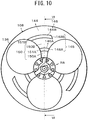
- the rotary disk 108 (108-100) is rotated at a predetermined speed, thereby stirring the coins C in the coin storing bowl 106. Due to this stirring, the coins C are dropped in apertures 136 formed at eccentric positions of the disk 108 and then, moved or rotated in conjunction with the rotation of the disk 108. In the event of a coin jam, in other words, when the state where the coins C are not dispensed due to jamming of the coins C occurs, the disk 108 is rotated in the reverse direction for the purpose of resolving the coin jam.
- the rotary disk 108 is rotatably mounted in the disk receiving hole 126 formed in the upper surface of the base 104. The disk 108 is rotated at a predetermined speed in a counterclockwise direction in Fig.
- the top end of the input shaft 46 is inserted into an attaching hole 138 formed at the center of the rotary disk 108 and fixed by a nut 140 which is screwed into the threaded part of the input shaft 46, where the threaded part is formed at the top end of the shaft 46 (see Fig. 7 ).
- the rotary disk 108 comprises a stirring part 142 having a shape like a truncated pyramid which is formed on the upper surface of the rotary disk 108 (See Figs. 7 and 8 ).
- the stirring part 142 is rotated in the bottom hole 134 of the bowl 106 in conjunction with the rotation of the disk 108. For this reason, the coins C in the bowl 106 can be stirred certainly and at the same time, the dropping of the coins C from the bowl 106 into the apertures 136 of the disk 108 can be facilitated.
- the rotary disks 108 (108-10, 108-100, 108-50 and 108-500) prepared for the respective coin dispensing units 22-10, 22-100, 22-50 and 22-500 have the same diameter, and the apertures 136 formed in the respective disks 108 are the same in number and are arranged at the same angular position.
- the number of the apertures 136 is three and the angular positions of the apertures 136 are at equal angles of 120 degrees.
- the diameter of the apertures 136 may be determined in such a way as to be optimized for the respective denominations or the same for coins with similar diameters.
- the apertures 136 for 10 yen coins 10C and those for 100 yen coins 100C are set to be the same, and the apertures 136 for 50 yen coins 50C and those for 500 yen coins 500C are respectively optimized for the coins 50C and 500C.
- the important point of the rotary disk 108 is that the number and angular position of the apertures 136 provided for the respective coin dispensing units 22-10, 22-100, 22-50 and 22-500 are the same. Since all of the rotary disks 108 of the four units 22 are simultaneously rotated and stopped, the coins C of all the denominations which are dropped into the apertures 136 need to be located at the same angular position in order to control the dispensing operation of the coins C. Therefore, it is important that the number and angular position of the apertures 136 for the four units 22 are the same.
- the meaning that the angular positions of the apertures 136 for the respective units 22 are the same is not limited to its strict meaning but includes the range where the coins of all the denominations are processed in the same way.
- the angular positions of the apertures 136 for the respective units 22 need not be strictly the same; the angular positions of the apertures 136 for the respective units 22 may be different from each other if the coins of all the denominations can be processed in the same way.
- a plurality of ribs 144 are formed among the apertures 136 of the rotary disk 108, and curved pressing members 146 are formed on the rear face 108R of the disk 108.
- Each pressing member 146 has a curved shape extending approximately radially with respect to the disk 108. The pressing members 146 are rotated in the disk receiving hole 126 in conjunction with the rotation of the disk 108.
- each pressing member 146 i.e., the pressing face
- the shape of the front face 148 of each pressing member 146 is such that the front face 148 is shifted backward as it approaches the periphery of the disk 108.
- first pressing members 146A are formed near the rotation axis RA and second pressing members 146B are formed near the periphery of the disk 108.
- first guide member portion 112A and a second guide member portion 112B both of which constitute the guide member 112 which will be described in detail later, to pass through
- arc-shaped first clearance grooves 150A are formed near the rotation axis RA and arc-shaped second clearance grooves 150B are formed between the first pressing members 146A and the second pressing members 146B.
- the front faces of the first pressing members 146A correspond to the first pressing faces 148A
- the front faces of the second pressing members 146B correspond to the second pressing faces 148B.
- an inclined face 154 which is directed downward toward the central part of the disk 108 from the peripheral part 152 thereof, is formed, as shown in Fig. 11 .
- the middle part 156 which is surrounded by the inclined face 154, is approximately flat.
- the neighborhood of the attaching hole 138 into which the input shaft 46 is inserted is mounded in such a way as to form a truncated pyramid, forming the stirring part 142.
- stirring protrusions 158 are formed on the upper faces of the ribs 144.
- a height adjusting mechanism or device 160 for adjusting the height of the disk 108 is mounted, as shown in Fig. 8 .
- the term "height” described here means the first distance H1 between the bottom face 128 of the base 104 and the rear face 108R of the disk 108, as shown in Fig. 7 .
- the height adjusting mechanism 160 has the function of adjusting the first distance H1 to an appropriate interval corresponding to the thickness of the coin C.
- the height adjusting mechanism 160 comprises an inner tube member 162 that protrudes downward from the center of the rear face 108R of the disk 108, an outer tube member 164 to be fitted on the outside of the inner tube member 162, and an engaging part 166 formed with reference to the inner and outer tube members 162 and 164.
- the inner tube member 162 constituting a part of the height adjusting mechanism 160 is a cylindrical member having a predetermined radius whose center is located at the rotation axis RA and a predetermined length, where the member 162 is placed around the attaching hole 138 of the disk 108.
- the inner tube member 162 is a cylindrical member protruding downward from the central part of the rear face 108R of the disk 108.
- a flange 170 with a predetermined thickness is formed to surround the member 162.
- the first height or distance H1 between the upper face of the flange 170 and the rear face 108R of the disk 108 is determined to be slightly larger than the second height H2 (see Fig.
- the foot 171 of the stirring part 142 will be relatively large and as a result, the inner tube member 162 will be entirely overlaid on the foot 171. Therefore, in this case, the flange 170 is unnecessary to be formed.
- the outer tube member 164 constituting another part of the height adjusting mechanism 160 is a cylindrical member having a predetermined length.
- the upper end of a fitting hole 172 formed in the outer tube member 164 can be fitted into the lower part of the inner tube member 162 (See Figs. 9A and 9B ).
- a penetrating hole 173 having a diameter smaller than the fitting hole 172 is formed to be concentric with the fitting hole 172.
- the fitting hole 172 and the penetrating hole 173 are formed continuously in the vertical direction, resulting in a stepped hole.
- the fitting hole 172 forming the upper part of the stepped hole has a larger diameter than the penetrating hole 173 forming the lower part thereof.
- the lower end face 174 of the outer tube member 164 is a flat face parallel to the upper face 151 of the rotary disk 108. For this reason, when the disk 108 is rotated in such a way that the lower end face 174 is in surface contact with an opposing face, the disk 108 will be rotated in a plane parallel to this opposed face.
- the engaging part 166 constituting the remaining part of the height adjusting mechanism 160 has the function of changing stepwise the second height or distance H2 between the lower end face 174 of the outer tube member 164 and the rear face 108R of the disk 108, and the function of eliminating the phase gap between the inner and outer tube members 162 and 164, as shown in Figs. 8 and 9A .
- the engaging part 166 comprises a disk-side engaging subpart 176 and an outer tube-side engaging subpart 178, as shown in Fig. 8 .
- the disk-side engaging subpart 176 has the function of blocking relative rotation of the outer tube member 164 with respect to the inner tube member 162 in cooperation with the outer tube-side engaging subpart 178.
- the disk-side engaging subpart 176 is a protrusion having a rectangular cross section, which is protruded downward from the back of the flange 170 of the inner tube member 162.
- the disk-side engaging subpart 176 is extended from the outer surface of the inner tube member 162 in a radial direction of the member 162 to the vicinity of the peripheral part of the flange 170. As clearly shown in Fig.
- the disk-side engaging subpart 176 is formed to have a Y-shaped structure by three elongated protrusions which have the same shape and which are arranged at equal angles of 120 degrees, i.e., a first elongated protrusion 176a, a second elongated protrusion 176b, and a third elongated protrusion 176c.
- the first elongated protrusion 176a, the second elongated protrusion 176b, and the third elongated protrusion 176c are formed to be radially with respect to the rotation axis RA.
- the count of these elongated protrusions may be one or two, or four or more.
- the first, second, and third elongated protrusions 176a, 176b and 176c have the same rectangular cross section and the same length.
- the third widths W3 of the first, second, and third elongated protrusions 176a, 176b and 176c are set to be equal to each other, as shown in Fig. 9A .
- the outer tube-side engaging subpart 178 has the function of setting stepwise the relative position of the outer tube member 164 with respect to the rear face 108R of the rotary disk 108, and the function of blocking relative rotation between the inner and outer tube members 162 and 164, both of which are realized in cooperation with the disk-side engaging subpart 176.
- the outer tube-side engaging subpart 178 comprises receiving recesses 180 having rectangular cross sections, which are formed on the disk-side end face (in other words, the upper end face) of the outer tube member 164.
- the count of the receiving recesses 180 is an integral multiple of the number of the disk-side engaging subparts 176.
- the number of the outer tube-side engaging subparts 178 is set to be an integral multiple of 2, such as 4, 6, and 8; moreover, the positional relationship among the outer tube-side engaging subparts 178 is determined in accordance with the arrangement of the disk-side engaging subparts 176.
- the count of the receiving recesses 180 is set to be three times as much as that of the disk-side engaging subparts 176. Concretely speaking, the number of the disk-side engaging subparts 176 is 3 and the count of the receiving recesses 180 is 9 (i.e., three times as much as 3).
- the first receiving recess 180a, the second receiving recess 180b, the third receiving recess 180c, the fourth receiving recess 180d, the fifth receiving recess 180e, the sixth receiving recess 180f, the seventh receiving recess 180g, the eighth receiving recess 180h, and the ninth receiving recess 180i are formed to have the same fourth width W4 at predetermined pitches on the upper face of the outer tube member 164.
- the first to ninth receiving recesses 180a to 180i are formed to be radially with respect to the rotation axis RA of the rotary disk 108.
- Each of the first to ninth receiving recess 180a to 180i has one of the first, second, and third depths D1, D2, and D3, and every three ones of the first to ninth receiving recess 180a to 180i are equal in depth.
- three of the first to ninth receiving recess 180a to 180i arranged at equal angles of 120 degrees, which are respectively opposed to the first, second, and third elongated protrusions 176a, 176b, and 176c, have the same depth of D1, D2 or D3.
- the first, fourth and seventh receiving recess 180a, 180d and 180g have the same depth of D1
- the second, fifth and eighth receiving recess 180b, 180e and 180h have the same depth of D2
- the third, sixth and ninth receiving recess 180c, 180f and 180i have the same depth of D3.
- the widths of the first to ninth receiving recess 180a to 180i are set to be equal to the fourth width W4 in such a way as to be detachably engaged with and to be closely fitted to a corresponding one of the first, second, and third elongated protrusions 176a, 176b, and 176c.
- the first to ninth receiving recess 180a to 180i have the same width of W4 and the depth of D1, D2 or D3.
- three of the receiving recess 180a to 180i arranged at every 120 degrees constitute one group.
- the first, fourth and seventh receiving recess 180a, 180d and 180g constitute one group; the second, fifth and eighth receiving recess 180b, 180e and 180h constitute another group; and the third, sixth and ninth receiving recess 180c, 180f and 180i constitute a last group.
- the engaging subpart 166 is formed as described there is an additional advantage that the rear face 108R of the rotary disk 108 and the lower face 174 of the outer tube member 164 can be made parallel easily.
- the width W4 of the first to ninth receiving recesses 180a to 180i is slightly wider than the width W3 of the first to third elongated protrusions 176a to 176c and therefore, each of the first to third elongated protrusions 176a to 176c can be fitted into a corresponding one of the first to ninth receiving recesses 180a to 180i.
- the depths of the first to ninth receiving recesses 180a to 180i are set to be equal to each other for each of the aforementioned three groups of the receiving recesses as explained in detail below.
- the first, fourth and seventh receiving recesses 180a, 180d and 180g arranged at equal angles of 120 degrees to form a Y shape have the first depth D1, which is the deepest.
- the second, fifth and eighth receiving recesses 180b, 180e and 180h arranged at equal angles of 120 degrees have the second depth D2, which is the second deepest.
- the third, sixth and ninth receiving recesses 180c, 180f and 180i arranged at equal angles of 120 degrees have the third depth D3, which is the shallowest.
- the first depth D1 is larger than the fourth height H4 of the disk-side engaging subpart 176.
- the third distance H3 between the rear face 108R of the disk 108 and the lower end face 174 of the outer tube member 164 is set at the smallest first distance D1d.
- the first distance D1d which is not shown in any figures, is generated by attaching "d" to the first distance D1 for the sake of explanation. The same manner is applied to the other distances in the following description.
- the lower ends of the first, second and third elongated protrusions 176a, 176b and 176c abut against the bottom faces of the second, fifth and eighth receiving recess 180b, 180e and 180h, respectively.
- the third distance H3 between the rear face 108R of the disk 108 and the lower end face 174 of the outer tube member 164 is equal to the second distance D2d which corresponds to the second depth D2 and which is slightly larger than the first distance D1d.
- the lower ends of the first, second and third elongated protrusions 176a, 176b and 176c abut against the bottom faces of the third, sixth and ninth receiving recess 180c, 180f and 180i, respectively.
- the third distance H3 between the rear face 108R of the disk 108 and the lower end face 174 of the outer tube member 164 is equal to the third distance D3d which corresponds to the third depth D3 and which is slightly larger than the second distance D2d.
- the inner tube member 152 and the outer tube member 164 are coupled together while the first, second and third elongated protrusions 176a, 176b, and 176c are respectively fitted into corresponding ones of the three groups of the first to ninth receiving recess 180a to 180i in accordance with the thickness of the coin C, resulting in the combination of the rotary disk 108 and the height adjusting mechanism 160. Then, this combination is mounted on the base 104 in such a way that the input shaft 46 is inserted into the attaching hole 138 of the disk 108 and that the outer tube member 164 is dropped into a circular bearing hole 182 formed at the center of the disk receiving hole 126.
- the interval between the rear face 108R of the disk 108 and the bottom face 128 of the disk receiving hole 126 is determined by the first distanced D1d, the second distance D2d, or the third distance D3d which is defined by the combination of the inner tube member 152 and the outer tube member 164.
- the 100 yen coins C dropped into the apertures 136 of the disk 108 are supported by surface contact of the surfaces or backs of the coins C with the base 104 and at the same time, the coins C are pressed and moved by the first pressing members 146A due to the rotation of the rotary disk 108, and guided by the coin guiding wall 130 of the disk receiving hole 126. In this way, the coins C are rotated along the coin carrying path MP in conjunction with the rotation of the disk 108.
- the rotary disk 108 is rotated in the reverse direction. Due to this reverse rotation, the back faces 151A and 151B of the first pressing member 146A and the second pressing member 146B press the peripheral faces of the coins C, thereby moving the coins C in an opposite direction to that of the forward rotation.
- the guide member 112 Since the guide member 112 is moved to the non-guiding point NGP when the rotary disk 108 is rotated in the reverse direction, the guide member 112 does not block the movement of the coins C along the carrying path MP. Therefore, the coins C are rotated in conjunction with the disk 108 in the reverse direction and the coin jam is eliminated due to the stirring action of the disk 108, resulting in preparation for restart.
- the dispensing opening 110 is an opening through which the coins C that have been moved along the carrying path MP can be moved radially from the disk receiving hole 126. As shown in Fig. 6 , the dispensing opening 110 is formed by removing a part of the circular coin guiding wall 130.
- the dispensing opening 110 is an opening formed by removing a part of the coin guiding wall 130 of the base 104 (more specifically, an upper part of the inclined section of the base 104) in such a way as to have a size greater than the maximum coin diameter.
- the dispensing opening 110 is a slit-shaped sideways opening defined by an upstream-side edge 130u of the coin guiding wall 130 and a downstream-side edge 130d thereof.
- the interval between the upstream-side edge 130u and the downstream-side edge 130d is greater than the diameter of the maximum-diameter coin C to be dispensed and less than twice as much as the maximum coin diameter.
- the interval between the upstream- and downstream-side edges 130u and 130d is set at about 1.2 times as much as the diameter of the maximum-sized 500 yen coin 500C.
- the dispensing passage 114 is extended linearly from the dispensing opening 110 along one radius of the disk receiving hole 126, as shown in Fig. 6 .
- the dispensing passage 114 has the function of guiding the coins C ejected from the dispensing opening 110 to a coin outlet 48.
- the dispensing passage 114 which has a recess-like shape, is formed by a passage bottom face 186 formed on an extension of the plane on which the bottom face 128 of the disk receiving hole 126 is positioned, a downstream-side guiding face 187 that defines the dispensing opening 110, and an upstream-side guiding face 189 of a dispensing opening adjustor 262 which will be described later.
- the dispensing passage 114 does not need to have a recess-like shape and may be formed by a flat face only. This means that the dispensing passage 114 can be formed by the passage bottom face 186 only. The end 188 of the passage bottom face 186 constitutes the coin outlet 48.
- the length of the dispensing passage 114 is approximately as much as the radius of the coin C; however, this length may be greater or less than the radius of the coin C.
- the guide member 112 has the function of guiding the coins C which are moved along the carrying path MP in conjunction with the rotation of the rotary disk 108 in a radial direction of the disk 108, in other words, a radial direction of the disk receiving hole 126.
- This function is a basic function and termed the "radial guiding function”.
- the guide member 112 has the function of allowing the coins C to be moved in the reverse direction along the carrying path MP in the case where the rotary disk 108 is rotated in the reverse direction for solving a coin jam and in the case where the coins C pressed by the back faces 150 ( Fig. 10 ) of the pressing members 146 are moved in the reverse direction along the carrying path MP.
- This function is termed the "reversal permitting function”.
- this function is not an essential function for the present invention.
- the guide member 112 has the further function of selectively guiding the coins C or not, as another basic function. This function is termed the "selective guiding function”.
- the guide member 112 has the function of ejecting the coins C to the dispensing passage 114, as another auxiliary function.
- This function is termed the "ejecting function".
- this function may be carried out by any type of ejecting device provided in addition to the guide member 112.
- the guide member 112 is configured to carry out the aforementioned four functions; however, the present invention is not limited to this. These four functions may be carried out separately, in other words, each of these four functions may be carried out by a single device. Two or three of these functions may be carried out by a single device also.
- the guide member 112 is selectively positioned at a guiding position GP (see Figs. 19A and 19B ) or a non-guiding position NGP (see Figs. 20A and 20B ) by a position selecting device 190, thereby performing the selective guiding function.
- the guide member 112 If the guide member 112 is positioned at the guiding position GP, it performs the radial guiding function for guiding the coins C in a radial direction of the rotary disk 108.
- the guide member 112 constitutes the ejecting device 116 in cooperation with a resilience device 192 and a dispensing opening adjustor 262 which will be described later.
- the guide member 112 performs its ejecting function in this way.
- the guide member 112 has the selective guiding function of guiding the coins C which are moved in conjunction with the rotation of the rotary disk 108 toward the dispensing opening 110.
- the guide member 112 has the ejecting function also.
- the guide member 112 is a bar-shaped member whose side view is linear.
- the lower end of the guide member 112 is rockably supported by a supporting shaft 194 and the upper end thereof is formed to be like a two-pronged fork in a front view. Therefore, it may be said that the guide member 112 comprises a first guide member portion 112A and a second guide member portion 112B that constitute the shape like a two-pronged fork.
- the first and second guide member portions 112A and 112B are arranged in such a way as to be respectively overlapped with the arc-shaped first clearance grooves 150A and the arc-shaped second clearance grooves 150B.
- the number of the guide member portions that constitute the guide member 112 may be one or three or more as long as they can perform the radial guiding function.
- a first inclined face 196A and a second inclined face 196B are respectively formed in such a way as to be inclined at 45 degrees with respect to the horizontal plane in the state where the first and second guide member portions 112A and 112B stand upright.
- the first and second guide member portions 112A and 112B are inclined until the angle between the portions 112A and 112B and the horizontal plane reaches about 60 degrees.
- the both ends of the supporting shaft 194 are fixed to a position selector 198 that constitutes a part of the position selecting device 190.
- the guide member 112 is moved to the guiding position GP through an advance/retreat hole 129 formed at a position opposed to the carrying path MP of the base 104 and furthermore, moved to the non-guiding position NGP from the guiding position GP.
- a first advance/retreat hole 129A and a second advance/retreat hole 129B are provided, which are slit-shaped and opposed to the first and second guide member portions 112A and 112B, respectively.
- the position selecting device 190 has the function of selectively moving the guide member 112 to the guiding position GP or the non-guiding position NGP. Accordingly, the position selecting device 190 may be replaced with other device having a similar function.
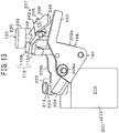
- the position selecting device 190 comprises the position selector 198 and an actuator 200, as shown in Figs. 12 to 14 .
- the position selector 198 of the position selecting device 190 has the function of selectively positioning the guide member 112 between the guiding position GP and the non-guiding position NGP. Concretely, when the position selector 198 is positioned at a dispensing assisting position AP (see Fig. 19B ), the selector 198 makes the guide member 112 positioned at the guiding position GP. When the position selector 198 is positioned at a non-dispensing assisting position NAP (see Fig. 20B ), the selector 198 makes the guide member 112 positioned at the non-guiding position NGP.
- the position selector 198 comprises a pair of a first sidewall 202a and a second sidewall 202b the side views of which are inverted triangular and which are arranged in parallel at a predetermined distance in a vertical direction, a rocking motion limiter 204 that interconnects the first sidewall 202a and the second sidewall 202b, and a spring receiver 209, as shown in Figs. 19B and 20B .
- the overall shape of the position selector 198 is like a hollow bag.
- a large part of the guide member 112 is placed closely between the first sidewall 202a and the second sidewall 202b, thereby limiting the movement of the guide member 112 along the supporting shaft 194.
- first rocking shaft 208a and a second rocking shaft 208b are respectively provided to protrude outwardly from their middle portions along the same axis in opposite directions.
- the first and second rocking shafts 208a and 208b are rockably supported by a first bracket 219a and a second bracket 219b, respectively, as shown in Fig. 14 .
- the first bracket 219a and the second bracket 219b are protruded downward from the back of the base 104 in such a way as to be parallel to each other at a predetermined interval.
- an attachment piece 222 having an engaging groove 221 is formed to protrude laterally from there.
- the engaging groove 221 is U-shaped in cross section.
- the rocking motion of the position selector 198 is limited by a position limiter 223 that can be engaged with a part (the spring receiver 209) of the position selector 198 at the dispensing assisting position AP.
- the position limiter 223 is a member fixed on the lower surface of the base 104.
- the rocking motion limiter 204 is a bar-shaped member formed laterally in such a way as to interconnect the first and second sidewalls 202a and 202b at their upper ends.
- the rocking motion limiter 204 is engaged with the guide member 112 which has been rocked in a predetermined direction by this rocking force, thereby limiting the relative rocking motion of the guide member 112 with respect to the rocking motion limiter 204.
- the rocking motion limiter 204 has a trapezoidal cross section.
- the rocking motion limiter 204 is configured in such a way as to be in surface contact with the guide member 112 when the limiter 204 is engaged with the guide member 112.
- the spring receiver 209 has the function of supporting fixedly one end of the ejecting spring 226 which gives a rocking force to the guide member 112.
- the spring receiver 209 is formed by a plate-shaped member that interconnects the first and second sidewalls 202a and 202b on the opposite side to the rocking motion limiter 204.
- the spring receiver 209 receives one end of the spring 226 stably at a flat surface of the receiver 209. The end of the spring 226 is fixed on this flat surface by an engaging member (not shown).
- the attachment piece 222 is formed to be integrated with the position selector 198.
- the attachment piece 222 is a plate-shaped member that protrudes outward laterally from the side of the spring receiver 209 formed at the upper end of the second sidewall 202b.
- the attachment piece 222 has a grove 221 in which a part of the output rod 212 of the actuator 200 which will be described later is fitted and engaged.
- the distance from the first and second rocking shafts 208a and 208b to the attachment piece 222 is shorter than the distance from the first and second rocking shafts 208a and 208b to a linking portion 260 which will be explained later. This is because the actuator 200 which can be placed in the small-sized coin dispensing unit 22-100 needs to be used.
- the position selector 198 further comprises the linking portion 260.
- the linking portion 260 has the function of moving a rocking lever 257 which serves as an interlocking device 242 described later.
- the linking portion 260 is positioned at the upper end of the first sidewall 202a and is like a linear bar-shaped member that protrudes laterally from the vicinity of the rocking motion limiter 204.
- the position selector 198 is positioned at the non-dispensing assisting position NAP
- the linking portion 260 is moved to a position where the linking portion 260 does not move a driven lever 258 which will be described later.
- the position selector 198 is positioned at the dispensing assisting position AP, the linking portion 260 is moved to a position where the linking portion 260 moves the driven lever 258.
- the actuator 200 of the position selecting device 190 has the function of selectively positioning the position selector 198 at the dispensing assisting position AP or the non-dispensing assisting position NAP based on an instruction from the control circuit 122 shown in Fig. 16 .
- an electric actuator, a mechanical actuator, or a fluidic actuator may be used as the actuator 200.
- An electric actuator 213 is preferably used as the actuator 200.
- the electric actuator 213 is a general term of actuators that provide or cause mechanical displacements by supplying currents, which includes the type where Joule heat is generated by supplying currents and the deformation amount of a shape-memory alloy is varied by using this heat and the type of linear motors.
- An electromagnetic actuator 214 is used as the electric actuator 213.
- the electromagnetic actuator 214 comprises a rectangular pillar-shaped body 216, an electromagnet 218 placed in the body 216, and the output rod 212 mounted in the body 216 as a movable core. When the electromagnet 218 is magnetized, the output rod 212 is pulled into the body 216. When the electromagnet 218 is de-magnetized, the output rod 212 is pushed out from the body 216 by the action of a spring 220 mounted on the outside of the rod 212 like a sheath.
- a large diameter part 223 is formed on the top end of the output rod 212 of the electromagnetic actuator 214.
- a small diameter part is formed below the large diameter part 223, with which the groove 221 for the attachment piece 222 is engaged.
- the attachment piece 222 is pressed against the lower face of the large diameter part 223 by the spring 220. Therefore, if the electromagnet 218 is magnetized, the output rod 212 is lowered or pulled in and thus, the position selector 198 is rocked counterclockwise in Figs. 19B and 20B to the dispensing assisting position AP by way of the large diameter part 23 and the attachment piece 222. As a result, the guide member 112 is positioned at the guiding position GP.
- the output rod 212 is raised or pushed out from the body 216 by the spring 220 and thus, the position selector 198 is rocked clockwise in Figs. 19B and 20B to the non-dispensing assisting position NAP. As a result, the guide member 112 is positioned at the non-guiding position NGP.
- the guide member 112 If the guide member 112 is positioned at the non-guiding position NGP, the movement of the coins C along the carrying path MP is not prevented. Thus, the guide member 112 performs the reversal permitting function also in the event that the guide member 112 is positioned at the non-guiding position NGP.
- the ejecting device 116 has the function of ejecting the coins C which have been guided to the dispensing opening 110 by the guide member 112 to the dispensing passage 114. This means that the ejecting device 116 has the "ejecting function".
- the ejecting device 116 comprises the guide member 112 and the resilience device 192.
- the resilience device 192 elastically biases the guide member 112 toward the side of the rocking motion limiter 204 of the position selector 198.
- the resilience device 192 is a resilient spring 226 as an elastic member 224 which is placed between the spring receiver 209 and the guide member 112.
- the first and second guide member portions 112A and 112B are rocked around the supporting shaft 194, a resilience force is accumulated in the resilient spring 226. If the pressing motion to the guide member portions 112A and 112B by the coin C is eliminated at a predetermined moment, the guide member portions 112A and 112B will be rocked lively in the reverse direction due to the resilience force accumulated in the resilient spring 226. Because of this reverse rocking motion, the first and second inclined faces 196A and 196B (more specifically, the first inclined face 196A) will eject the coin C to the dispensing passage 114.
- the coin sensor 118 has the function of detecting the coin C ejected by the ejecting device 116.
- a magnet-type metal sensor 231 is used as the coin sensor 118. Therefore, the coin sensor 118 may be replaced with other device having a similar function, such as a photoelectric sensor, a mechanical sensor, and so on. As shown in Fig. 6 , the coin sensor 118 is located to be opposite to the dispensing passage 114. However, the coin sensor 118 may be located in the downstream side of the coin outlet 48.
- the passage blocking member 120 When the guide member 112 is located at the non-guiding position NGP, the passage blocking member 120 is located at the blocking position SP ( Fig. 20 ), thereby blocking the coin C which is moved in conjunction with the rotation of the rotary disk 108 so as not to be moved to the dispensing passage 114 from the dispensing opening 110.
- the passage blocking member 120 When the guide member 112 is located at the guiding position GP, the passage blocking member 120 is located at the non-blocking position NSP ( Fig. 19 ), thereby allowing the coin C to be moved to the dispensing passage 114 from the dispensing opening 110.
- the passage blocking member 120 is movably inserted into an appearance/disappearance hole 228 formed in the passage bottom face 186 of the dispensing passage 114 which is adjacent to the dispensing opening 110.
- the passage blocking member 120 can be moved perpendicular to the passage bottom face 186.
- the passage blocking member 120 is protruded from the appearance/disappearance hole 228 to the dispensing passage 114, thereby blocking the movement of the coin C through the dispensing passage 114.
- the passage blocking member 120 is retracted from the dispensing passage 114 through the appearance/disappearance hole 228 (in other words, retracted to the downside of the dispensing passage 114), allowing the movement of the coin C through the dispensing passage 114.
- the appearance/disappearance hole 228 has a shape of an elongated rectangle whose corners are rounded. The length of the hole 228 is set so as to cover about one-third (1/3) of the length of the dispensing opening 110.
- the passage blocking member 120 is a bar-shaped member extending perpendicular to the passage bottom face 186, which comprises a stopper part 232 formed at the top end part 230, a cooperation part 236 extended downward from the top end part 230, a retainer part 238 located below the cooperation part 236, and a small diameter part 240 formed next to the retainer part 238, as shown in Figs. 12 to 14 .
- the stopper part 232 (i.e., the top end part 230) of the passage blocking member 120 has the function of making contact with the coin C to thereby block its movement toward the dispensing passage 114.
- the stopper part 232 has a similar shape to the appearance/disappearance hole 228 in a plan view, which is slightly smaller than that of the hole 228.
- the thickness of the stopper part 232 is larger than the thickness of the base 104 in such a way that the stopper part 232 is guided by the inner wall face of the appearance/disappearance hole 228 to produce a linear reciprocating motion of the passage blocking member 120 along its longitudinal axis.
- the present invention is not limited to this.
- the thickness of the stopper part 232 may be smaller than the thickness of the base 104.
- the shape of the member 120 also is not limited to this.
- the member 120 may have any other shape like a circular bar, a polygonal pillar, or a triangular pillar.
- the cooperation part 236 of the passage blocking member 120 has the function of moving the member 120 to the non-blocking position NSP or the blocking position SP in interlocking with the movement of the guide member 112 to the guiding position GP or non-guiding position NGP.
- the cooperation part 236 has the function of carrying the movement of the interlocking device 242 which will be described later to the member 120 in order to move the member 120 to the non-blocking position NSP or the blocking position SP in interlocking with the movement of the position selector 198 to the dispensing assisting position AP or the non-dispensing assisting position NAP.
- the cooperation part 236 is formed by a guiding part 244 comprising a first face 236A and a second face 236B formed in parallel to each other at a predetermined interval.
- the guiding part 244 serving as the cooperation part 236 is sandwiched by a U-shaped part 248 of an interlocking member 246 which will be described later.
- the first face 236A and the second face 236B of the guiding part 244 are respectively opposed to a first pinching portion 248A and a second pinching 248B formed in parallel to each other at a predetermined interval which constitute the U-shaped part 248.
- a spring 252 serving as a biasing member 250 is mounted around the small diameter part 240 of the passage blocking member 120.
- the upper end of the spring 252 is abutted on the lower face of the retainer part 238 of the member 120, and the lower end thereof is abutted on a bracket 254 (see Figs. 19B and 20B ) which is formed on the back of the base 104 to be integrated therewith. Therefore, the passage blocking member 120 is biased upward with respect to the base 104 by the resilience force of the spring 252. In other words, the member 120 is biased in such a way as to be protruded upward from the passage bottom face 186 of the dispensing passage 114.
- the amount of protrusion of the member 120 is determined by abutting the retainer part 238 onto the interlocking member 246.
- the member 120 due to the downward motion of the retainer portion 238 caused by rocking the interlocking member 246, the member 120 (the top end part 230) is pulled into the appearance/disappearance hole 228 until at least the top end face of the member 120 reaches the same level as the passage bottom face 186.
- the interlocking device 242 has the function of interlocking the guide member 112 and the passage blocking member 120. In other words, the interlocking device 242 has the function of placing the passage blocking member 120 at the non-blocking position NSP if the guide member 112 is located at the guiding position GP, and placing the passage blocking member 120 at the blocking position SP if the guide member 112 is located at the non-guiding position NGP.
- a mechanical linking mechanism 241 is used as the interlocking device 242. More specifically, the mechanical linking mechanism 241 is formed by the rocking lever 257 as the plate-shaped interlocking member 246.
- a third supporting shaft 256 which is rotatably supported by the bearings (not shown) protruded downward from the lower side face of the base 104, is provided at the middle part of the rocking lever 257.
- the U-shaped part 248 is formed at one end of the interlocking member 246 constituting the interlocking device 242 (the mechanical linking mechanism 241).
- the U-shaped part 248 is used to sandwich the cooperation part 236 of the passage blocking member 120 at the first face 236A and the second face 236B thereof.
- the retainer portion 238 of the passage blocking member 120 is pressed down by the U-shaped part 248.
- the passage blocking member 120 is pressed down into the appearance/disappearance hole 228 to reach the non-blocking position NSP.
- a driven lever 258 is formed to extend linearly to have a predetermined length.
- the passage blocking member 120 is pushed upward by the spring 252 as the biasing member 250 to be moved to the blocking position SP. If the position selector 198 is moved to the dispensing assisting position AP, the passage blocking member 120 is moved downward against the resilience of the spring 252 and stopped at the blocking position SP defined in the dispensing passage 114 while protruding the stopper part 232 of the member 120 from the passage bottom face 186.
- the position selector 198 is located at the non-dispensing assisting position NAP and therefore, the linking portion 260 does not press the driven lever 258 from the downside.
- the passage blocking member 120 is pushed upward by the resilience force of the spring 252 and moved until the retainer part 238 is prevented from moving by the U-shaped part 248.
- the passage blocking member 120 is pushed upward and the top end part 230 of the member 120 is protruded from the passage bottom face 186, thereby placing the member 120 at the blocking position SP where the stopper part 232 crosses the dispensing passage 114.
- the position selector 198 is engaged by the position limiter 223.
- the output rod 212 is pulled downward in Fig. 12 and therefore, the position selector 198 is rocked counterclockwise in Fig. 19B around the supporting shaft 194 to reach the dispensing assisting position AP. Consequently, the linking portion 260 pushes the driven lever 258 upward from the downside and the driven lever 258 (and therefore, the U-shaped part 248) pushes the retainer part 238 downward against the resilience of the spring 252. In this way, the stopper part 232 is pulled into the appearance/disappearance hole 228 and retracted from the dispensing passage 114, reaching the non-blocking position NSP. As clearly seen from Fig.
- the linking portion 260 and the interlocking member 246 are arranged so as to form an acute angle in a plan view. Because of this arrangement and structure, there is an advantage that the guide member 112 and the passage blocking member 120 can be interlocked with each other with a mechanical linking mechanism at a low cost even in the small-sized coin dispensing unit 22-100.
- the dispensing opening adjustor 262 has the function of adjusting the interval DT between adjustor 262 and the downstream-side guiding face 187 in accordance with the diameter of the coin C to define the dispensing opening 110 of the coin C.
- the dispensing opening adjustor 262 further has the function of dispensing the coin C as a part of the ejecting device 116 also. This means that the dispensing opening adjustor 262 sandwiches the coin C in cooperation with the guide member 112 (specifically, the second guide member portion 112B) and finally, the second guide member portion 112B ejects the coin C.
- the dispensing opening adjustor 262 is trapezoidal plate-shaped in a plan view. As seen from Fig.
- the adjustor 262 comprises an upper part 264 and a lower part 266, where the upper part 264 is wider than the lower part 266.
- a boundary face 268A and a boundary face 268B are formed at the boundary between the upper and lower parts 264 and 266.
- the dispensing opening adjustor 262 has a stepped exterior.
- a position adjusting groove 270 is formed on the passage bottom face 186 of the dispensing passage 114, as shown in Fig. 6 .
- This groove 270 is linearly extended toward the downstream-side edge 130d from the upstream-side edge 130u and reaches the center of the dispensing passage 114.
- the longitudinal cross section of the groove 270 comprises a relatively wider upper groove 272 and a relatively narrower lower groove 274, where a boundary face 270A and a boundary face 270B are formed between the upper and lower grooves 272 and 274.
- the position adjusting groove 270 forms a stepped hole.
- the dispensing opening adjustor 262 is inserted into the position adjusting groove 270. Specifically, the lower and upper parts 266 and 264 of the dispensing opening adjustor 262 are slidably inserted closely in the lower and upper grooves 274 and 272 of the groove 270, respectively. In other words, the dispensing opening adjustor 262 is extended linearly along the groove 270 and can be contacted with the downstream-side guiding face 187.
- a penetrating threaded hole 276 is formed vertically.
- the top of the dispensing opening adjustor 262 is cylindrically depressed. This is to allow the head 281 of a fixing screw 280 to be buried in this depression 278. If the fixing screw 280 is penetrated through the threaded hole 276 of the adjustor 262, and a nut 281A which is abutted onto the back of the base 104 is thrust into the end of the screw 288, thereby sandwiching the base 104 (the boundary faces 270A and 270B) by the nut 281A and the dispensing opening adjustor 262.
- the dispensing opening adjustor 262 can be fixed on the base 104 at a suitable position in accordance with the diameter of the coin C.
- the distance between a coin engaging part 282 of the dispensing opening adjustor 262 and the downstream-side edge 130d of the coin guiding wall 130 is set to be slightly larger than the diameter of the coin C, wherein the coin engaging part 282 is formed at a corner of the adjustor 262.
- the center CC of the coin C does not pass through the line L1 that connects the contact point of the second guide member portion 112B and the coin C and the contact point of the coin C and the coin engaging part 282.
- the positional relationship among the guide member portion 112B, the coin engaging part 282, and the supporting shaft 194 is determined in this way. This means that the coin C can be ejected as long as the resilience force of the resilience spring 226 that is applied to the guide member 112 is equal to a predetermined value or greater. Because of such the relationship, there is an advantage that dispensing errors of the coin C can be prevented from occurring.
- the dispensing opening adjustor 262 is located at a position close to the passage blocking member 120. If the position of the adjustor 262 is adjusted to a position corresponding to the 500 yen coin 500C having the maximum diameter, the adjustor 262 is located at a position shown in Fig. 6 . Even in the latter case, the interval between the member 120 and the adjustor 262 is set to be smaller than the diameter of the minimum-sized 50 yen coin 50C. This is to prevent the minimum-sized 50 yen coins 50C to pass through this interval.
- the rotary encoder 127 has the function of outputting information about the angular position (phase) of the rotary disk 108.
- the rotary encoder 127 has the function of detecting the angular position (phase) of the disk 108 in order to prevent the disk 108 from being stopped in the state where the coin C moved in conjunction with the rotation of the disk 108 is overlaid on the advance/retreat hole 129 for the guide member 112.
- the rotary encoder 127 may be replaced with another device having a similar function.
- the rotary encoder 127 is mounted below the intermediate base 36 and comprises a slit disk 127A and a photoelectric sensor 127B.
- the disk 127A is fixed to the reducer output shaft 32 and has slits 127S formed on its annular periphery at constant intervals.
- the photoelectric sensor 127B is fixed to the intermediate base 36 and detects the slits 127S on the disk 127A to output an angular position signal APS.
- the rotary encoder 127 is not limited to the type of the first embodiment and may be provided at a position which is rotatable in synchronization with any one of the driven gears 42 for the other denominations.
- Three slits 127S are formed at equal intervals of 120 degrees. These slits 127S are used to detect the angular positions (phases) of the apertures 136 of the disks 108 (108-10, 108-100, 108-50 and 108-500).
- the control circuit 122 of the coin dispensing apparatus 10 controls the coin dispensing apparatus 10 including the coin dispensing units 22-10, 22-100, 22-50 and 22-500.
- the control circuit 122 has the function of receiving a dispensing instruction PO of the coins C from the control section (not shown) of an upper system or device (e.g., a POS register), an angular position signal APS of the rotary disks 108-10, 108-100, 108-50 and 108-500 from the rotary encoder 127, and coin signals CP-10, CP-100, CP-50, and CP-500 from the coin sensors 118-10, 118-100, 118-50 and 118-500, and turning on or off the electromagnetic actuators 214-10, 214-100, 214-50 and 214-500 in accordance with a predetermined program.
- an upper system or device e.g., a POS register
- coin signals CP-10, CP-100, CP-50, and CP-500 from the coin sensors 118-10, 118-100, 118-50 and 118-500
- control circuit 122 energizes or de-energizes the electromagnetic actuators 214-10, 214-100, 214-50 and 214-500. Moreover, the control circuit 122 has the function of instructing the electric motor 28 to rotate in the forward or reverse direction or to stop also.
- the control circuit 122 is configured by a microcomputer 286.
- the control circuit 122 When the control circuit 122 receives a dispensing signal PO of dispensing a designated amount of the coins C from the control section of the upper device, the control circuit 122 calculates necessary denominations and necessary numbers of the coins C to be dispensed, and magnetizes selectively the electromagnets 218 of the electromagnetic actuators 214-10, 214-100, 214-50 and/or 214-500 of the coin dispensing units 22-10, 22-100, 22-50 and/or 22-500 according to the necessity, thereby moving the position selectors 198 to the dispensing assisting positions AP by way of the output rods 202 and the attachment pieces 222, and moving the passage blocking members 120 to the non-blocking positions NSP by way of the interlocking devices 242.
- the guide members 112 are located at the guiding positions GP in the coin dispensing units 22-10, 22-100, 22-50 and/or 22-500.
- the control circuit 122 when receiving the dispensing signal PO, the control circuit 122 outputs a forward rotation signal to the electric motor 28 to rotate the reducer output shaft 32, the driving spur gear 38S, the idler gear 40-500, the driven spur gear 42S-500, the idler gear 40-50, the driven spur gear 42S-50, the idler gear 40-100, the driven spur gear 42S-100, the idler gear 40-10, and the driven spur gear 42S-10, thereby synchronously rotating the rotary disks 108-10, 108-100, 108-50 and 108-500. Furthermore, the control circuit 122 selectively magnetizes the electromagnetic actuators 214-10.
- the electromagnet 218 of each of the electromagnetic actuators 214 is de-magnetized, thereby moving the position selector 198 to the non-dispensing assisting position NAP and the guide member 112 to the non-guiding position NGP. After the guide member 112 is moved to the non-guiding position NGP, the supply of electric power to the electric motor 28 is stopped.
- the timing for stopping the supply of electric power to the motor 28 is controlled based on the angular position signal APS from the encoder 127 and as a result, the movement of the coins C is stopped in such way that the coins C are not overlaid on the advance/retreat hole 129.
- the coins C thus dispensed are detected by the respective metal sensors 118-10, 118-100, 118-50 and 118-500.
- these sensors 118-10, 118-100, 118-50 and 118-500 output the coin signals CS-10, CS-100, CS-50 and CS-500 to the control circuit 122.
- the control circuit 122 judges whether or not the coin signals CS-10, CS-100, CS-50 and CS-500 are equal to the numbers for the respective denominations designated by the dispensing instruction PO, in other words, whether or not the numbers included in the coin signals CS-10, CS-100, CS-50 and CS-500 are respectively equal to the designated numbers.
- the control circuit 122 keeps energizing the corresponding electromagnetic actuator 214. As a result, the guide member 112 is kept at the guiding position GP, thereby keeping the dispensing action of the coins C in the corresponding coin dispensing unit 22.
- the control circuit 122 de-energizes the corresponding electromagnetic actuator 214 and therefore, the position selector 198 is moved to the non-dispensing assisting position NAP.
- the guide member 112 is moved to the non-guiding position NGP and the passage blocking member 120 is moved to the blocking position SP, thereby stopping the dispensing action of the coin C in the corresponding coin dispensing unit 22.
- the step S1 it is judged whether the dispensing instruction PO (i.e., the dispensing amount PQ of the coins C) is outputted or not from the control section of the upper system. If the dispensing instruction PO is outputted, the operation flow advances to the step S2, and if the dispensing instruction PO is not outputted, the step S1 is repeatedly carried out so as to make a loop, in other words, the waiting state is continued. It is supposed that the designated dispensing amount PQ is set at 870 yen as an example.
- the control circuit 122 calculates the denomination and number of the coins C corresponding to the designated dispensing amount PQ, and outputs them thus calculated. Thereafter, the operation flow advances to the step S3.
- the calculated number of the 500 yen coin 500C is one
- the calculated number of the 100 yen coin 100C is three
- the calculated number of the 50 yen coin 50C is one
- the calculated number of the 10 yen coin 10C is two.
- step S3 the initial positioning process by reverse rotation is carried out. Then, the operation flow advances to the step S4.
- the "initial positioning process by reverse rotation” is a process for surely preventing the state where the coins C dropped into the apertures 136 of the disks 108-10, 108-100, 108-50, and 108-500 are overlaid on the advance/retreat holes 129 through which the guide members 112 are protruded or retracted in the coin dispensing units 22-10, 22-100, 22-50 and 22-500.
- the common electric motor 28 is rotated in the reverse direction to synchronously rotate all the disks 108-10, 108-100, 108-50 and 108-500 until a first detection signal ES is outputted from the photoelectric sensor 127B. When the output of a first detection signal ES is detected, the reverse rotation of the motor 28 is stopped.
- each of the disks 108-10, 108-100, 108-50 and 108-500 is stopped after the initial positioning process by reverse rotation is completed, the coins C dropped into the apertures 136 are not overlaid on the advance/retreat holes 129.
- the electromagnetic actuator 214 is not magnetized and therefore, the guide member 112 is positioned at the non-guiding positon NGP and the passage blocking member 120 is positioned at the blocking position SP. Accordingly, even if the coins C reach the dispensing opening 110 due to the revere rotation of the disk 108-10, 108-100, 108-50 or 108-500, the coins C cannot pass through the opening 110, which means that the coins C are not dispensed through the coin outlets 48.
- step S4 it is judged which denomination of the coins C is to be dispensed in accordance with the denomination and number of the coins C calculated in the step S2. Thereafter, the operation flow advances to the step S5 for individually controlling the coin dispensing units 22 which are assigned to the respective denominations.
- the electromagnetic actuator 214 of the coin dispensing unit 22 is magnetized according to the judgment result in the previous step S4. Specifically, if the unit 22 deals with the denomination to be dispensed, the electromagnetic actuator 214 of the said unit 22 is magnetized, and if the unit 22 does not deal with the denomination to be dispensed, the electromagnetic actuator 214 of the said unit 22 is not magnetized. Thereafter, the operation flow advances to the step S6.
- the designated dispensing amount PQ is 870 yen
- all the denominations i.e., 500 yen, 100 yen, 50 yen and 10 yen
- the electromagnets 218 of the actuators 214-500, 214-50, 214-100 and 214-10 of all the coin dispensing units 22-500, 22-50, 22-100 and 22-10 are magnetized and thereafter, the step 6 is carried out.
- the electromagnet(s) 218 of the actuator(s) 214 of the unit(s) 22 concerned is/are not magnetized.
- the output rod 212 of the actuator 214 is pulled into the body 216 thereof. Then, the position selector 198 is rocked counterclockwise in Fig. 20B by way of the attachment piece 222 engaged with the output rod 212, reaching the dispensing assisting position AP. As a result, the guide member 112 is moved to the guiding position GP and the linking portion 260 presses the driven lever 258 upward. Thus, the rocking lever 257 (the interlocking member 246) is rocked around the third supporting shaft 256, and the U-shaped part 248 presses the retainer portion 238 of the passage blocking member 120 downward. As a result, the top end of the member 120 is retreated into the appearance/disappearance hole 228.
- step S6 the electric motor 28 is activated in each of the coin dispensing units 22. Thereafter, the operation flow advances to the step S7.
- step S6 due to the activation of the motor 28, the output shaft 32 of the reducer 30 is rotated at a predetermined speed and as a result, the driving gear 38 and the slit disk 127A of the rotary encoder 127 are rotated at predetermined speeds.
- the driven spur gear 42S-500 is rotated by way of the idler gear 40-500 which is engaged with the driving gear 38 is rotated
- the driven spur gear 42S-50 is rotated by way of the idler gear 40-50 which is engaged with the driven gear 42-500
- the driven spur gear 42S-100 is rotated by way of the idler gear 40-100 which is engaged with the driven gear 42-50
- the driven spur gear 42S-10 is rotated by way of the idler gear 40-10 which is engaged with the driven gear 42-100, at the same speed in the same direction.
- the rotary disks 108-500, 108-100, 108-50 and 108-10 are rotated by way of the input shafts 46-500, 46-100, 46-50 and 46-10, respectively.
- the apertures 136 formed in the respective disks 108-500, 108-100, 108-50 and 108-10 are respectively rotated in the forward direction by the same angle.
- the coins C placed in the apertures 136 are then pressed by the pressing members 146 to be moved along the carrying paths MP formed on the base 104.
- the 100 yen coins 100C which are being moved by the first pressing members 146A are guided toward the side of the dispensing opening 110 by the first and second guide member portions 112A and 112B.
- the coins 100C Due to the movement of the coins C toward the side of the dispensing opening 110, the coins 100C will be able to be guided by the coin engaging part 282 of the dispensing opening adjustor 262. During such the time period, the pressing action of the first pressing members 146A to the coins C is maintained. For this reason, the second guide member portion 112B is rocked against the resilience force of the resilience spring 226 to reach the position shown by a broken line in Fig. 20B .
- the 100 yen coins 100C are further moved along the radial direction of the disk receiving hole 126.
- the coins 100C are moved by only the second pressing members 146B.
- the center CC of the coin 100C exceeds the first line L1 that connects the contact point of the second guide member portion 112B and the periphery of the coin 100C and the contact point of the coin 100C and the coin engaging part 282 at the position shown in Fig. 20A .
- the coin 100C that has exceeded the line L1 is vigorously ejected by the resilience force of the spring 226 to the dispensing passage 114.
- the 100 yen coin 100C thus ejected to the dispensing passage 114 is detected by the metal sensor 118.
- the metal sensor 118 outputs the coin signal CS.
- step S6 about the 100 yen coins 100C is applicable to the coins C of 10 yen, 50 yen and 500 yen.
- the electromagnet(s) 218 of the actuator(s) 214 of the coin dispensing unit(s) 22 concerned is/are not magnetized.
- the guide member 112 is positioned at the non-guiding positon NGP and the passage blocking member 120 is positioned at the blocking position SP. Accordingly, even if the coin C reaches the dispensing opening 110 due to the revere rotation of the disk 108, the coin C cannot pass through the opening 110, which means that the coin C is not dispensed through the coin outlet 48 and kept being moved along the carrying path MP.
- step S7 the denomination of the coins C to be dispensed is discriminated. Then, the operation flow advances to the step S8.
- steps S8 to S14 relate to the dispensing processes of the individual coin dispensing units 22-500, 22-50, 22-100 and 22-10, where the coins C are separated and dispensed in the respective units 22. Therefore, the steps S8 to S14 are carried out in parallel in the individual units 22-500, 22-50, 22-100 and 22-10.
- a hyphen and the denomination will be attached to the same step number, e.g., S8-100, S8-10, S8-500 and S8-50.
- the content or operation in each of the steps S8 to S14 is the same, the content or operation in the coin dispensing unit 22-100 will be explained below and that of the other units 22-500, 22-50 and 22-10 is omitted for the sake of simplification.
- step S8-100 measurement of the dispensing judging time T1 is started. Thereafter, the flow advances to the step S9-100.
- the "dispensing judging time T1" is a reference time for judging whether it is an abnormal state or not.
- the abnormal state is the state where the 100 yen coins 100C supposed to have been dispensed are not detected by the metal sensor 118 through the whole dispensing judging time T1, in other words, none of the coins 100C are not dispensed to the dispensing passage 114 in spite of the state where the coins 100C are to be dispensed.
- the dispensing judging time T1 is usually set at about 3 seconds, for example.
- step S9-100 it is judged whether the coin signal CS is outputted from the metal sensor 118 or not. If the coin signal CS is outputted from the sensor 118, the flow advances to the step S10-100, and if the coin signal CS is not outputted from the sensor 118, the flow advances to the step S11-100. As explained above, when the sensor 118 detects the coin 100C and outputs the coin signal CS, the coin dispensing unit 22-100 operates successfully or normally and thus, the flow advances to the next step S10-100 for the normal operation.
- step S11-100 it is judged whether the dispensing judging time T1 has expired or not. If the dispensing judging time T1 has not expired, the flow is returned to the step S9-100. If the time T1 has expired, the flow advances to the step S15-100. Specifically, since the guide member 112 is located at the guiding position GP in the step S5-100 and the rotary disk 108-100 is rotated in the step S6, the 100 yen coin 100C is to be dispensed and the coin signal CS is to be outputted from the metal sensor 118 within the dispensing judging time T1 in the step S9-100.
- step S10-100 the number of the coin signals CS is counted whenever the coin signal CS is outputted. Thereafter, the flow advances to the step S12-100. In the step S10-100, since this is the first time, "1" is counted. In other words, the number of the dispensed coins C is counted as "1".
- step S12-100 it is judged whether the dispensing number CN of the 100 yen coins 100C (the counted value in the step S10-100) is equal to the designated dispensing number DN or not, in other words, whether the dispensing number CN of the coins 100C has reached the designated dispensing number DN or not. If the dispensing number CN has reached the designated dispensing number DN, the flow advances to the step S13-100. If the dispensing number CN has not reached the designated dispensing number DN, the flow returns to the step S9-100. This means that whether the designated predetermined number of the 100 yen coins 100C was dispensed or not is judged in the step S12-100.
- the designated dispensing number DN is set at 3. Since the dispensing number CN thus counted from the coin signal CS this time is 1, it is judged that the dispensing number CN has not reached the designated dispensing number DN. So, the flow is returned to the step S9-100 and the dispensing action of the 100 yen coins 100C continues.
- the coins 100C are ejected by the guide member 112 one by one, and the coin signal CS is outputted from the metal sensor 118-100 at every dispensing action. Therefore, when two more coins 100C are further dispensed later and the dispensing number CN thus counted reaches 3, the flow advances to the step S13-100.
- step S13-100 the electromagnetic actuator 214-100 is de-energized. Thereafter, the flow advances to the step S14-100.
- the position selector 225 is moved to the non-dispensing assisting position NAP by the resilience force of the spring 220 and the guide member 112 is moved to the non-guiding position NGP.
- the pressing action of the linking portion 250 to the rocking lever 257 (the interlocking member 246) is eliminated.
- the passage blocking member 120 is pushed upward by the biasing force of the spring 252 as the biasing member 250, and the stopper part 232 of the member 120 is protruded from the appearance/disappearance hole 228 to the dispensing passage 114 adjacent to the dispensing opening 110. In this way, the member 120 is located at the blocking position SP.
- step S14-100 a dispensing completion signal FS100 is outputted. Thereafter, the flow advances to the step S31.
- step S15-100 is carried out, wherein the electromagnet 218 of the electromagnetic actuator 214-100 is de-magnetized. Thereafter, the flow advances to the step S16-100.
- step S15-100 due to de-magnetization of the electromagnet 218, as explained previously, the guide member 112 is located at the non-guiding position NGP and the dispensing judging 120 is located at the blocking position SP, thereby preventing the coins 100C from being dispensed. Subsequently, in the next step S16-100, a request for reverse rotation of the rotary disk 108-100 is issued to eliminate a coin jam automatically. Thereafter, the coin jam eliminating process in the step S17 and later will be performed.
- the aforementioned coin dispensing process from the step S8-100 to the step S16-100 in the coin dispensing unit 22-100 is carried out in the coin dispensing units 22-500, 22-50 and 22-10 also.
- the calculated denominations and numbers of the 500 yen coins 500C, the 50 yen coins 50C and the 10 yen coins 10C corresponding to the designated dispensing amount PQ of 870 yen are dispensed.
- one 500 yen coin 500C is dispensed from the coin dispensing unit 22-500 and then, a dispensing completion signal FS 500 is outputted.
- one 50 yen coin 50C is dispensed from the coin dispensing unit 22-50 and then, a dispensing completion signal FS 50 is outputted.
- Two 10 yen coins 10C are dispensed from the coin dispensing unit 22-10 and then, a dispensing completion signal FS 10 is outputted.
- next steps S31 it is judged whether all the dispensing completion signals FS100, FS10, FS500 and FS50 are outputted or not. If all the dispensing completion signals FS100, FS10, FS500 and FS50 are outputted, the flow advances to the step S32. If all the dispensing completion signals FS100, FS10, FS500 and FS50 are not outputted, the step S31 is repeatedly carried out so as to make a loop, in other words, the waiting state is continued.
- step S32 it is judged whether the angular position signal APS which is suitable to halt of the rotary disks 108 has been outputted or not from the rotary encoder 127. If such the signal APS has been outputted, the operation flow advances to the step S11, and if such the signal APS has not been outputted, the step S32 is repeated. This is to detect the timing of halting the supply of electric power to the electric motor 28 in such a way that the rotary disks 108 do not stop in the state where the respective coins 10C, 100C, 50C and 500C are respectively opposed to the guide members 112 in the coin dispensing units 22-10, 22-100, 22-50 and 22-500.
- step S33 the supply of electric power to the electric motor 28 is stopped and thereafter, the coin dispensing operation is finished. Since the supply of electric power to the motor 28 is stopped, the rotation of the rotary disks 108-10, 108-100, 108-50 and 108-500 will stop synchronously after some rotation(s) caused by inertia. Since the timing of stopping the electric power supply is adjusted in such a way that all the coins 10C, 100C, 50C and 500C are not overlaid on the corresponding advance/retreat holes 129, there arises no inconvenience for a next dispensing operation.
- the initial positioning process by reverse rotation in the step S3 may be omitted; however, in the case where the dispensing operation is not carried out for a long time, there is a possibility that at least one of the disks 108 is rotated by an external force so that the coin C is overlaid on a corresponding one of the advance/retreat holes 129. Therefore, it is preferred to perform this initial positioning process.
- step S17 the supply of electric power to the electric motor 28 is stopped. Because of stopping the electric power supply, the rotation of all the disks 108 is stopped, thereby preventing the dispensing operation of the coins C. Subsequently, the operation flow advances to the step S18.
- step S18 all the disks 108 are rotated in the reverse direction by way of the transmission device 26 due to the reverse rotation of the motor 28.
- all the coins C are also moved in the reverse direction along the carrying path MP because these coins C are pressed by the back faces 151A and 151B of the first and second pressing members 146A and 146B.
- the guide members 112 are located at the non-guiding positions NGP and therefore, the coins C are moved in the reverse direction without any inconvenience and/or any problem.
- the flow advances to the step S19.
- step S19 measurement of the reverse rotation time T2 is started.
- the "reverse rotation time T2" determines the rough amount of the reverse rotation of the disks 108. It is sufficient for the disks 108 to be reverse rotated by at least about 30 degrees. However, it is preferred that the disks 108 are designed to be reverse-rotated by approximately one turn. Thereafter, the flow advances to the step S20.
- step S20 it is judged whether the reverse rotation time T2 has reached or not the "standard reverse rotation time ST2" which is determined in advance. If the reverse rotation time T2 has reached the standard reverse rotation time ST2, the flow advances to the step S21. If the reverse rotation time T2 has not reached the standard reverse rotation time ST2, the step S20 is repeated so as to form a loop. For this reason, the disks 108 are reverse-rotated during the standard reverse rotation time ST2.
- step S21 the reverse rotation of the motor 28 is stopped. Because of stopping the supply of electric power to the motor 28, the reverse rotation of all the disks 108 will stop after some rotation(s) caused by inertia. Thereafter, the flow advances to the step S22.
- step S22 all the electromagnets 218 of the electromagnetic actuators 214 are magnetized. Due to magnetization of the electromagnets 218, all the position selectors 198 are rocked counterclockwise in Fig. 19B to reach the dispensing assisting positions AP. Therefore, the guide members 112 are moved to the guiding positions AP, and the stopper parts 232 of the passage blocking members 120 are pulled into the appearance/disappearance holes 228 and retracted from the dispensing passages 114 to reach the non-blocking positions NSP by the linking portions 260. Thus, the coin dispensing operations are enabled in all the coin dispensing units 22. Thereafter, the flow advances to the step S23.
- step S23 the motor 28 is rotated in the forward direction. Due to the forward rotation of the motor 28, all the disks 108 are rotated in the forward direction by way of the transmission device 26. This is to verify whether or not the coin jam has been eliminated by the first-time reverse rotation of the disks 108. Thereafter, the flow advances to the step S24.
- step S24 it is judged whether or not the coin signal CS is outputted from any one of the coin sensors 118 of the coin dispensing units 22 in the dispensing judging time T1. If the coin signal CS is outputted, the flow advances to the steps S25-500, S25-50, S25-100 and S25-10. If the coin signals CS are not outputted, the step S24 is repeatedly carried out so as to make a loop. This is because it can be supposed that the disk 108 is rotated normally if the coin signal CS is outputted.
- step S25-500 it is judged whether or not the coin signal CS is outputted from the coin sensor 118 in the dispensing judging time T1 in the coin dispensing unit(s) 22 in which the coin signal CS has not been outputted in the step S24. If the coin signal CS is outputted in the step S25-500, S25-50, S25-100 or S25-10, the flow returns to the step S7. This is because it is presumed that the disk 108 in the corresponding unit 22 is being rotated normally. In this case, forward the rotation of the motor 28 is continued and the undispensed number of the coins C will be dispensed.
- step S26 If the coin signal CS is not outputted in the steps S25-500, S25-50, S25-100 and S25-10, the flow advances to the step S26. This is because it is presumed that all the disks 108 are not being rotated normally.
- step S26 the rotation of the motor 28 is stopped. Due to the stop of the motor 28, the dispensing operation of the coins C is stopped. Thereafter, the flow advances to the step S27.
- step S27 the reverse rotation number CRN is counted.
- the reverse rotation number CRN is incremented by "1" whenever the reverse rotation is performed once. Since this is the first-time reverse rotation, "1" is added to the value of the reverse rotation number CRN and stored. Thereafter, the flow advances to the step S28.
- the reverse rotation number CRN is compared with the reverse rotation acceptable number CAN. If the reverse rotation number CRN is equal to or less than the reverse rotation acceptable number CAN, the flow is returned to the step S18. If the reverse rotation number CRN is greater than the reverse rotation acceptable number CAN, the flow advances to the step S29.
- the reverse rotation acceptable number CAN is set at 3. Since this is the first-time reverse rotation, the reverse rotation number CRN is 1 and less than the value 3 of CAN. Thus, the flow is returned to the step S18.
- the reverse rotation process from the step S18 to the step S28 is carried out again.
- the reverse rotation number CRN is incremented by 1 to have the value of 2. Since this is the second-time reverse rotation, it is judged that reverse rotation number CRN of 2 is less than the value 3 of CAN.
- the flow is returned to the step S18 again and the coins C are dispensed again.
- step S29 an abnormal state signal ES is outputted to the upper system and then, the coin dispensing operation is finished.
- the rotary disks 108 of the four coin dispensing units 22 are simultaneously rotated or stopped by the common driving device 20 by way of the transmitting device 26. Due to the rotation of the disks 108, the coins C are dropped in the apertures 136 of the respective disks 108 and then, sent to the coin outlets 48 in the respective coin dispensing units 22.
- the passage blocking member 120 is provided in the dispensing opening 110 of each of the coin dispensing units 22 in such a way as to be selectively positioned at the non-blocking position NSP or the blocking position SP while simultaneously rotating the disks 108 of the four coin dispensing units 22.
- the passage blocking member 120 of the corresponding coin dispensing unit 22 is positioned at the non-blocking position NSP, allowing the coins C to pass through the dispensing passage 110.
- the passage blocking member 120 of the corresponding unit 22 is positioned at the blocking position SP, preventing the coins C from passing through the dispensing passage 110.
- the passage blocking member 120 When the guide member 112 provided in the carrying path MP is located at the guiding position GP, the passage blocking member 120 is located at the non-blocking position NSP, and when the guide member 112 is located at the non-guiding position NGP, the passage blocking member 120 is located at the blocking position SP. Therefore, even if the coins C are not naturally moved to the dispensing passage 110, the coins C can be surely guided and sent to the dispensing passage 110 by the guide member 112. On the other hand, when the coins C need not to be dispensed, the passage blocking member 120 is located at the blocking position SP and the guide member 112 is located at the non-guiding position NGP. As a result, the movement of the coins C toward the dispensing passage 110 can be surely prevented by the passage blocking member 120, thereby avoiding false dispensing of the coins C.
- the rotary disks 108 of all the coin dispensing units 22 are simultaneously rotated or stopped by the common driving device 20 by way of the transmitting device 26, the rotation of the disks 108 are kept until the coins C of the necessary denominations are completely dispensed by prescribed numbers by the coin dispensing units 22. This means that the dispensing operations of the coins C in the respective units 22 are carried out in parallel.
- the dispensing operations of all the coin dispensing units can be completed within a shorter time than the case where the dispensing operations of all the coin dispensing units 22 are carried out in series.
- the fabrication cost of the coin dispensing apparatus 10 can be lowered.
- the coin dispensing apparatus 10 is capable of dispensing the coins C of a plurality of denominations surely and more quickly compared with the aforementioned prior-art apparatuses and capable of being fabricated at a low cost.
- the four coin dispensing units 22 are aligned closely along the conveying belt 16, and the rotary disks 108 of all the coin dispensing units 22 are driven by the common electric motor 28 by way of the transmission device 26. Therefore, the coin dispensing apparatus 10 is easy to be downsized.
- the transmission device 26 is configured by a series of spur gears. Unlike this, in the coin dispensing apparatus 10A according to the second embodiment, a transmission device 26A is configured by using bevel gears.
- the diameter of each gear can be set smaller than the case where spur gears are used. Therefore, the gears used for the transmission device 26A can be downsized and as a result, there is an additional advantage that the coin dispensing apparatus 10A can be decreased in size compared with the coin dispensing apparatus 10 of the aforementioned first embodiment.
- the rotary disks 108 are mounted horizontally in the coin dispensing apparatus 10A of the second embodiment, which is unlike the coin dispensing apparatus 10 of the first embodiment where the disks 108 are mounted obliquely.
- the overall configuration and operation of the apparatus 10A of the second embodiment is substantially the same as those of the apparatus 10 of the first embodiment other than the attitude of the disks 108 and the configuration of the transmission device 26A.
- the speed reducer 30 is fixed laterally on a plate-shaped bracket 50 that protrudes backward from the chassis 24, as shown in Figs. 24 and 27 .
- the four coin dispensing units 22 (22-10, 22-100, 22-50 and 22-500) are arranged closely along the straight line on the chassis 24 in this order, as shown in Fig. 22 .
- the common electric motor 28 also, which is fixed on the speed reducer 30, is placed laterally, as shown in Fig. 27 .
- the output shaft 32 of the reducer 30 penetrates through the bracket 50, protruding laterally.
- the transmission device 26A in the second embodiment has the same function as that of the transmission device 26 in the first embodiment and comprises at least a common driving shaft transmission device 52 shown in Fig. 26 and a coin dispensing unit driving device 54 shown in Fig. 25 .
- the common driving shaft transmission device 52 has the function of transmitting the rotation of the output shaft 32 of the reducer 30 to the coin dispensing unit driving device 54.
- the device 52 comprises a driving pulley 56, a driving belt 58, a driven pulley 60 and a tension roller 62.
- the driving pulley 56 is fixed onto the top end of the reducer output shaft 32.
- the driven pulley 60 is fixed to one end of a common driving shaft 64.
- the common driving shaft 64 constitutes a part of the coin dispensing unit driving device 54 and will be described later.
- the driving belt 58 is stretched between the driving pulley 56 and the driven pulley 60.
- the tension roller 62 is mounted to apply a pressing force to the driving belt 58 in order to maintain a predetermined tension.
- the common driving shaft 64 is driven by the driving device 20 (i.e., the electric motor 28 and the speed reducer 30) by way of the common driving shaft transmission device 52. Since the common driving shaft transmission device 52 is provided between the common driving shaft 64 and the driving device 20, the driving device 20 can be placed in parallel to the arrangement line of the four coin dispensing units 22, as shown in Figs. 24 and 25 . This leads to an advantage that the length of the arrangement line of the units 22 can be shortened. If the length of the arrangement line of the units 22 is not taken into consideration, it is possible to omit the common driving shaft transmission device 52 and to directly drive the common driving shaft 64 by the reducer output shaft 32.
- the coin dispensing unit driving device 54 has the function of transmitting the driving force of the driving device 20 to the input shafts 46 (46-10, 46-100, 46-50 and 46-500) of the coin dispensing units 22 (22-10, 22-100, 22-50 and 22-500).
- the device 54 comprises the aforementioned common driving shaft 64, four driving bevel gears 66-10, 66-100, 66-50 and 66-500, and four driven bevel gears 68-10, 68-100, 68-50 and 68-500.
- the common driving shaft 64 has a function of rotating the driving bevel gears 66-10, 66-100, 66-50 and 66-500.
- the common driving shaft 64 is rotatably supported by four bearings 70-1, 70-2, 70-3 and 70-4 so as to be parallel to the intermediate base 36.
- These bearings 70-1, 70-2, 70-3 and 70-4 are arranged at predetermined intervals along the arrangement line of the coin dispensing units 22 and fixed in a downward direction to the back side of the intermediate base 36. Therefore, the common driving shaft 64 is parallel to the arrangement line of the units 22.
- the driving bevel gears 66 (66-10, 66-100, 66-50 and 66-500) have a function of rotating the driven bevel gears 68 (68-10, 68-100, 68-50 and 68-500).
- These driving bevel gears 66 are fixed to the common driving shaft 64 so as to be concentric with the same in the vicinity of the bearings 70-1, 70-2, 70-3 and 70-4.
- spiral bevel gears 66H-10, 66H-100, 66H-50 and 66H-500 are respectively used as the bevel gears 66-10, 66-100, 66-50 and 66-500.
- spiral bevel gears which may be termed "Hypoid gears” (registered trademark), are engaged with each other in such a way that a plurality of teeth of one spiral bevel gear are simultaneously meshed with a plurality of teeth of the other, thereby dispersing the force applied to each tooth. This leads to an advantage that endurance and silence are excellent.
- the driven bevel gears 68 are respectively driven by the driving bevel gears 66 and has a function of driving the coin dispensing units 22, in other words, a function of rotating the rotary disks 108 thereof.
- the driven bevel gears 68 are fixed to the lower ends of the input shafts 46 and are respectively engaged with the driving bevel gears 66.
- spiral bevel gears 68H-10, 68H-100, 68H-50 and 68H-500 are respectively used as the bevel gears 68-10, 68-100, 68-50 and 68-500.
- the driving bevel gears 66 and the driven bevel gears 68 are the same in structure, material and size. This is to reduce the fabrication cost due to mass production effects of parts and to prevent false assembling.
- each of the input shafts 46 (46-10, 46-100, 46-50 and 46-500) is formed by a driven-side part 46P and a driving-side part 46G.
- the driving-side parts 46G are commonalized. This is to reduce the fabrication cost due to commonalization of the parts for the chassis 24 and to facilitate the fabrication processes.
- the driving-side part 46G is formed by a driving-side input shaft part 46D and a driving-side clutch part 74D.
- the driven bevel gear 68 (68-100) is fixed to the lower end of the driving-side input shaft part 46D, and the driving-side clutch part 74D is fixed to the upper end of the input shaft part 46D.
- the intermediate part of the input shaft part 46D is rotatably supported by an input bearing 72 fixed to the intermediate base 36, as shown in Fig. 27 .
- the input shaft part 46D is extended along the vertical direction with respect to the intermediate base 36.
- the upper end of the input shaft part 46D which is a disk-side end of the driving-side part 46G, is directed toward the rotary disk 108 (108-100).
- the driving-side clutch part 74D that constitutes a part of an engaging clutch 74 is located at the upper end of the input shaft part 46D.
- the driving-side clutch part 74D comprises pen tip-shaped protrusions 78D and pen tip-shaped voids 78S.
- the clutch part 74D needs to have at least one combination of the protrusion 78D and the void 78S.
- the protrusions 78D and the voids 78S are formed by forming arrow-shaped notches along the axial line AC in the driving-side cylindrical member which is fixed onto the upper end of the input shaft part 46D.
- the driven-side part 46P is formed by a disk-side input shaft part 46R and a driven-side clutch part 74P.
- the rotary disk 108 (108-100) is fixed to the upper end of the disk-side input shaft part 46R, and the driven-side clutch part 74P is fixed to the lower end of the input shaft part 46R.
- the driven-side clutch part 74P has the same shape as that of the driving-side clutch part 74D.
- the driven-side clutch part 74P comprises pen tip-shaped protrusions 80D and pen tip-shaped voids 80S.
- the number of the combinations of the protrusion 80D and the void 80S is the same as that of the protrusion 78D and the void 78S.
- the driving-side clutch part 74D has three pairs of the pen tip-shaped protrusions 78D and the pen tip-shaped voids 78S, and the driven-side clutch part 74P also has three pairs of the pen tip-shaped protrusions 80D and the pen tip-shaped voids 80S.
- the protrusions 78D of the driving-side clutch part 74D are fitted into the corresponding voids 80S of the driven-side clutch part 74P, and the protrusions 80D of the driven-side clutch part 74P are fitted into the corresponding voids 78S of the driving-side clutch part 74D.
- the driven-side clutch part 74P (which is relatively smaller in rotational resistance than the driving-side clutch part 74D) is pressed and turned by the protrusions 80D to result in an engaged connection between the clutch parts 74D and 74P.
- the rotary disks 108 of the four coin dispensing units 22 are synchronously rotated by way of the clutches 74.
- the rotation of the reducer output shaft 32 as the output shaft of the driving device 20 is transmitted to the common driving shaft 64 by way of the driving pulley 56, the driving belt 58, and the driven-pulley 60, as shown in Fig. 26 .
- the driving bevel gears 66 (66-10, 66-100, 66-50 and 66-500) are rotated and then, the driven bevel gears 68 (68-10, 68-100, 68-50 and 68-500) which are engaged with the driving bevel gears 66 are rotated.
- the rotation of the driven bevel gears 68 are transmitted to the rotary disks 108 (108-10, 108-100, 108-50 and 108-500) of the coin dispensing units 22 (22-10, 22-100, 22-50 and 22-500) by way of the driving-side input shaft parts 46D, the driving-side clutch parts 74D, the driven-side clutch parts 74P which are engaged with the clutch parts 74D, and the driven-side part 46P.
- the coins C are dispensed by the rotation of the disks 108 (108-10, 108-100, 108-50 and 108-500) in the same way as that of the aforementioned first embodiment.
- the structure and operation are substantially the same as those of the coin dispensing apparatus 10 according to the first embodiment except for the transmission device 26A and the attitude of the rotary disks 108. Therefore, it is apparent that the same advantages as those of the apparatus 10 according to the first embodiment are obtained.
- the coin dispensing apparatus 10A of the first embodiment has an additional advantage that the apparatus 10A can be decreased in size compared with the apparatus 10 of the first embodiment, because the bevel gears are used for the transmission device 26A.
- the guide member and the passage blocking member are bar-shaped.
- the present invention is not limited to this.
- the guide member and the passage blocking member may have any other shape as long as their necessary functions are realized.
Landscapes
- Physics & Mathematics (AREA)
- General Physics & Mathematics (AREA)
- Pinball Game Machines (AREA)
- Control Of Vending Devices And Auxiliary Devices For Vending Devices (AREA)
- Testing Of Coins (AREA)
Applications Claiming Priority (1)
| Application Number | Priority Date | Filing Date | Title |
|---|---|---|---|
| JP2014011447A JP6182787B2 (ja) | 2014-01-24 | 2014-01-24 | 複数硬貨払出装置 |
Publications (2)
| Publication Number | Publication Date |
|---|---|
| EP2899697A1 EP2899697A1 (en) | 2015-07-29 |
| EP2899697B1 true EP2899697B1 (en) | 2017-06-21 |
Family
ID=52000762
Family Applications (1)
| Application Number | Title | Priority Date | Filing Date |
|---|---|---|---|
| EP14196107.8A Active EP2899697B1 (en) | 2014-01-24 | 2014-12-03 | Coin dispensing apparatus |
Country Status (6)
| Country | Link |
|---|---|
| US (1) | US9202325B2 (https=) |
| EP (1) | EP2899697B1 (https=) |
| JP (1) | JP6182787B2 (https=) |
| KR (2) | KR101765124B1 (https=) |
| CN (1) | CN104809797B (https=) |
| ES (1) | ES2637776T3 (https=) |
Families Citing this family (12)
| Publication number | Priority date | Publication date | Assignee | Title |
|---|---|---|---|---|
| JP6337275B2 (ja) | 2015-06-09 | 2018-06-06 | 旭精工株式会社 | コインホッパ |
| CN106056739B (zh) * | 2016-07-13 | 2018-10-30 | 厦门大学嘉庚学院 | 螺旋叶面硬币分拣、清点与包装装置及其使用方法 |
| JP6837316B2 (ja) * | 2016-11-11 | 2021-03-03 | 東芝テック株式会社 | 出金装置、決済装置およびプログラム |
| CN109863539B (zh) * | 2016-11-22 | 2021-11-12 | 日本功勒克斯股份有限公司 | 硬币批量投入装置 |
| JP6958869B2 (ja) * | 2019-02-20 | 2021-11-02 | 旭精工株式会社 | 多連硬貨投出装置 |
| JP2020135414A (ja) * | 2019-02-20 | 2020-08-31 | 日本金銭機械株式会社 | コイン送出ユニットおよびそれを用いたコイン処理装置 |
| JP6958871B2 (ja) | 2019-03-04 | 2021-11-02 | 旭精工株式会社 | 多連硬貨投出装置 |
| US20210150843A1 (en) * | 2019-11-20 | 2021-05-20 | Scott D. Sherrod | Systems and methods for monitoring a coin-operated device |
| JP2021149760A (ja) * | 2020-03-23 | 2021-09-27 | グローリー株式会社 | 硬貨処理装置 |
| JP7315250B2 (ja) * | 2020-09-15 | 2023-07-26 | 旭精工株式会社 | コインホッパ、コインホッパの回転体、およびコイン処理装置 |
| EP4057241B1 (en) * | 2021-03-08 | 2025-04-23 | Scan Coin Ab | Coin bridge counteraction in a coin handling device |
| CN113066342A (zh) * | 2021-03-29 | 2021-07-02 | 浙江工业职业技术学院 | 一种经济管理教学用erp物理沙盘 |
Family Cites Families (14)
| Publication number | Priority date | Publication date | Assignee | Title |
|---|---|---|---|---|
| US1721511A (en) * | 1926-05-14 | 1929-07-23 | Standard Johnson Co Inc | Coin-handling machinery |
| JPS5014419B1 (https=) * | 1969-08-06 | 1975-05-27 | ||
| JP2514825B2 (ja) | 1987-10-31 | 1996-07-10 | 日本電気ホームエレクトロニクス株式会社 | 金庫装置 |
| KR970005402B1 (ko) * | 1992-11-02 | 1997-04-16 | 아사히 세이꼬 가부시끼가이샤 | 경화송출장치 |
| JPH08320961A (ja) | 1995-05-24 | 1996-12-03 | Nippon Conlux Co Ltd | 硬貨処理装置 |
| JP3060916U (ja) * | 1999-01-20 | 1999-09-14 | ユニテック工業株式会社 | 並行連動型駆動装置 |
| JP3994131B2 (ja) * | 2001-12-28 | 2007-10-17 | 旭精工株式会社 | コインの払出装置 |
| JP4031941B2 (ja) * | 2002-03-20 | 2008-01-09 | グローリー株式会社 | コイン繰出装置 |
| US8216032B2 (en) * | 2007-03-29 | 2012-07-10 | Glory Ltd. | Coin dispensing device and coin processing machine |
| JP4129542B2 (ja) | 2007-05-14 | 2008-08-06 | 旭精工株式会社 | コイン払出装置及びコインメックのコイン払出装置 |
| JP5838432B2 (ja) * | 2011-04-11 | 2016-01-06 | 旭精工株式会社 | コイン搬送装置およびコイン払出装置 |
| ES2564380T3 (es) * | 2010-12-10 | 2016-03-22 | Asahi Seiko Co., Ltd. | Dispositivo de transferencia de discos y dispositivo de distribución de discos |
| IT1402831B1 (it) * | 2010-12-10 | 2013-09-27 | Alberici S P A | Dispositivo per discriminare ed erogare monete |
| JP5884117B2 (ja) * | 2013-07-21 | 2016-03-15 | 旭精工株式会社 | 硬貨払出装置 |
-
2014
- 2014-01-24 JP JP2014011447A patent/JP6182787B2/ja active Active
- 2014-12-03 ES ES14196107.8T patent/ES2637776T3/es active Active
- 2014-12-03 EP EP14196107.8A patent/EP2899697B1/en active Active
- 2014-12-22 CN CN201410805940.8A patent/CN104809797B/zh active Active
-
2015
- 2015-01-14 KR KR1020150006847A patent/KR101765124B1/ko active Active
- 2015-01-22 US US14/603,168 patent/US9202325B2/en active Active
-
2016
- 2016-09-19 KR KR1020160119099A patent/KR101727100B1/ko active Active
Non-Patent Citations (1)
| Title |
|---|
| None * |
Also Published As
| Publication number | Publication date |
|---|---|
| KR20150088720A (ko) | 2015-08-03 |
| JP6182787B2 (ja) | 2017-08-23 |
| US9202325B2 (en) | 2015-12-01 |
| KR20160113527A (ko) | 2016-09-29 |
| EP2899697A1 (en) | 2015-07-29 |
| US20150213665A1 (en) | 2015-07-30 |
| ES2637776T3 (es) | 2017-10-17 |
| JP2015138510A (ja) | 2015-07-30 |
| KR101727100B1 (ko) | 2017-04-14 |
| KR101765124B1 (ko) | 2017-08-04 |
| CN104809797A (zh) | 2015-07-29 |
| CN104809797B (zh) | 2018-02-09 |
Similar Documents
| Publication | Publication Date | Title |
|---|---|---|
| EP2899697B1 (en) | Coin dispensing apparatus | |
| JP2015138510A5 (https=) | ||
| CN103871152B (zh) | 硬币料斗 | |
| EP2830025B1 (en) | Coin dispensing apparatus | |
| US10255744B2 (en) | Disk transferring device and disk dispensing device | |
| KR20110055336A (ko) | 푸쉬업 통로를 가진 코인 호퍼 | |
| WO2004023404A1 (ja) | 硬貨釣銭機 | |
| EP1612744B1 (en) | Coin dispensing apparatus for large coins | |
| JP5732640B2 (ja) | コイン搬送装置およびコイン払出装置 | |
| EP1889230B1 (en) | System and method for payout of coins from multiple coin storage units | |
| JP2013008117A5 (https=) | ||
| JP2012221281A (ja) | コイン搬送装置およびコイン払出装置 | |
| WO2008010722A1 (en) | System and method for storage and delivery of product units | |
| EP3654301B1 (de) | Vorrichtung zum vereinzeln, prüfen und weiterleiten von münzen | |
| EP2443972A1 (en) | System for feeding capsules containing a food product for producing a beverage or the like, particularly for vending machines | |
| JP3709771B2 (ja) | コイン払出装置 | |
| CN107111905B (zh) | 硬币支出装置 | |
| JP6145604B2 (ja) | ディスク選別装置およびディスク選別アセンブリ並びにそれを用いたディスク処理方法 | |
| JP3759213B2 (ja) | パチンコ機における賞品球排出装置 | |
| JP5457254B2 (ja) | 遊技機の球払出装置 | |
| JP5095336B2 (ja) | 自動販売機等の硬貨投入口装置 | |
| JP2014135055A5 (https=) | ||
| MX2007015030A (en) | System and method for payout of coins from multiple coin storage units | |
| HK1237108A1 (en) | Coin payout device |
Legal Events
| Date | Code | Title | Description |
|---|---|---|---|
| PUAI | Public reference made under article 153(3) epc to a published international application that has entered the european phase |
Free format text: ORIGINAL CODE: 0009012 |
|
| 17P | Request for examination filed |
Effective date: 20141203 |
|
| AK | Designated contracting states |
Kind code of ref document: A1 Designated state(s): AL AT BE BG CH CY CZ DE DK EE ES FI FR GB GR HR HU IE IS IT LI LT LU LV MC MK MT NL NO PL PT RO RS SE SI SK SM TR |
|
| AX | Request for extension of the european patent |
Extension state: BA ME |
|
| 17P | Request for examination filed |
Effective date: 20150625 |
|
| RBV | Designated contracting states (corrected) |
Designated state(s): AL AT BE BG CH CY CZ DE DK EE ES FI FR GB GR HR HU IE IS IT LI LT LU LV MC MK MT NL NO PL PT RO RS SE SI SK SM TR |
|
| 17Q | First examination report despatched |
Effective date: 20151021 |
|
| RIC1 | Information provided on ipc code assigned before grant |
Ipc: G07D 9/00 20060101ALI20170119BHEP Ipc: G07D 3/00 20060101ALN20170119BHEP Ipc: G07D 1/00 20060101AFI20170119BHEP |
|
| GRAP | Despatch of communication of intention to grant a patent |
Free format text: ORIGINAL CODE: EPIDOSNIGR1 |
|
| INTG | Intention to grant announced |
Effective date: 20170228 |
|
| GRAS | Grant fee paid |
Free format text: ORIGINAL CODE: EPIDOSNIGR3 |
|
| GRAA | (expected) grant |
Free format text: ORIGINAL CODE: 0009210 |
|
| AK | Designated contracting states |
Kind code of ref document: B1 Designated state(s): AL AT BE BG CH CY CZ DE DK EE ES FI FR GB GR HR HU IE IS IT LI LT LU LV MC MK MT NL NO PL PT RO RS SE SI SK SM TR |
|
| REG | Reference to a national code |
Ref country code: GB Ref legal event code: FG4D |
|
| REG | Reference to a national code |
Ref country code: CH Ref legal event code: EP |
|
| REG | Reference to a national code |
Ref country code: IE Ref legal event code: FG4D |
|
| REG | Reference to a national code |
Ref country code: AT Ref legal event code: REF Ref document number: 903563 Country of ref document: AT Kind code of ref document: T Effective date: 20170715 |
|
| REG | Reference to a national code |
Ref country code: DE Ref legal event code: R096 Ref document number: 602014010944 Country of ref document: DE |
|
| REG | Reference to a national code |
Ref country code: ES Ref legal event code: FG2A Ref document number: 2637776 Country of ref document: ES Kind code of ref document: T3 Effective date: 20171017 |
|
| REG | Reference to a national code |
Ref country code: NL Ref legal event code: MP Effective date: 20170621 |
|
| PG25 | Lapsed in a contracting state [announced via postgrant information from national office to epo] |
Ref country code: GR Free format text: LAPSE BECAUSE OF FAILURE TO SUBMIT A TRANSLATION OF THE DESCRIPTION OR TO PAY THE FEE WITHIN THE PRESCRIBED TIME-LIMIT Effective date: 20170922 Ref country code: LT Free format text: LAPSE BECAUSE OF FAILURE TO SUBMIT A TRANSLATION OF THE DESCRIPTION OR TO PAY THE FEE WITHIN THE PRESCRIBED TIME-LIMIT Effective date: 20170621 Ref country code: HR Free format text: LAPSE BECAUSE OF FAILURE TO SUBMIT A TRANSLATION OF THE DESCRIPTION OR TO PAY THE FEE WITHIN THE PRESCRIBED TIME-LIMIT Effective date: 20170621 Ref country code: NO Free format text: LAPSE BECAUSE OF FAILURE TO SUBMIT A TRANSLATION OF THE DESCRIPTION OR TO PAY THE FEE WITHIN THE PRESCRIBED TIME-LIMIT Effective date: 20170921 Ref country code: FI Free format text: LAPSE BECAUSE OF FAILURE TO SUBMIT A TRANSLATION OF THE DESCRIPTION OR TO PAY THE FEE WITHIN THE PRESCRIBED TIME-LIMIT Effective date: 20170621 |
|
| REG | Reference to a national code |
Ref country code: LT Ref legal event code: MG4D |
|
| REG | Reference to a national code |
Ref country code: AT Ref legal event code: MK05 Ref document number: 903563 Country of ref document: AT Kind code of ref document: T Effective date: 20170621 |
|
| PG25 | Lapsed in a contracting state [announced via postgrant information from national office to epo] |
Ref country code: RS Free format text: LAPSE BECAUSE OF FAILURE TO SUBMIT A TRANSLATION OF THE DESCRIPTION OR TO PAY THE FEE WITHIN THE PRESCRIBED TIME-LIMIT Effective date: 20170621 Ref country code: SE Free format text: LAPSE BECAUSE OF FAILURE TO SUBMIT A TRANSLATION OF THE DESCRIPTION OR TO PAY THE FEE WITHIN THE PRESCRIBED TIME-LIMIT Effective date: 20170621 Ref country code: NL Free format text: LAPSE BECAUSE OF FAILURE TO SUBMIT A TRANSLATION OF THE DESCRIPTION OR TO PAY THE FEE WITHIN THE PRESCRIBED TIME-LIMIT Effective date: 20170621 Ref country code: BG Free format text: LAPSE BECAUSE OF FAILURE TO SUBMIT A TRANSLATION OF THE DESCRIPTION OR TO PAY THE FEE WITHIN THE PRESCRIBED TIME-LIMIT Effective date: 20170921 Ref country code: LV Free format text: LAPSE BECAUSE OF FAILURE TO SUBMIT A TRANSLATION OF THE DESCRIPTION OR TO PAY THE FEE WITHIN THE PRESCRIBED TIME-LIMIT Effective date: 20170621 |
|
| PG25 | Lapsed in a contracting state [announced via postgrant information from national office to epo] |
Ref country code: CZ Free format text: LAPSE BECAUSE OF FAILURE TO SUBMIT A TRANSLATION OF THE DESCRIPTION OR TO PAY THE FEE WITHIN THE PRESCRIBED TIME-LIMIT Effective date: 20170621 Ref country code: EE Free format text: LAPSE BECAUSE OF FAILURE TO SUBMIT A TRANSLATION OF THE DESCRIPTION OR TO PAY THE FEE WITHIN THE PRESCRIBED TIME-LIMIT Effective date: 20170621 Ref country code: SK Free format text: LAPSE BECAUSE OF FAILURE TO SUBMIT A TRANSLATION OF THE DESCRIPTION OR TO PAY THE FEE WITHIN THE PRESCRIBED TIME-LIMIT Effective date: 20170621 Ref country code: AT Free format text: LAPSE BECAUSE OF FAILURE TO SUBMIT A TRANSLATION OF THE DESCRIPTION OR TO PAY THE FEE WITHIN THE PRESCRIBED TIME-LIMIT Effective date: 20170621 Ref country code: RO Free format text: LAPSE BECAUSE OF FAILURE TO SUBMIT A TRANSLATION OF THE DESCRIPTION OR TO PAY THE FEE WITHIN THE PRESCRIBED TIME-LIMIT Effective date: 20170621 |
|
| PG25 | Lapsed in a contracting state [announced via postgrant information from national office to epo] |
Ref country code: IS Free format text: LAPSE BECAUSE OF FAILURE TO SUBMIT A TRANSLATION OF THE DESCRIPTION OR TO PAY THE FEE WITHIN THE PRESCRIBED TIME-LIMIT Effective date: 20171021 Ref country code: SM Free format text: LAPSE BECAUSE OF FAILURE TO SUBMIT A TRANSLATION OF THE DESCRIPTION OR TO PAY THE FEE WITHIN THE PRESCRIBED TIME-LIMIT Effective date: 20170621 Ref country code: PL Free format text: LAPSE BECAUSE OF FAILURE TO SUBMIT A TRANSLATION OF THE DESCRIPTION OR TO PAY THE FEE WITHIN THE PRESCRIBED TIME-LIMIT Effective date: 20170621 |
|
| REG | Reference to a national code |
Ref country code: DE Ref legal event code: R097 Ref document number: 602014010944 Country of ref document: DE |
|
| PLBE | No opposition filed within time limit |
Free format text: ORIGINAL CODE: 0009261 |
|
| STAA | Information on the status of an ep patent application or granted ep patent |
Free format text: STATUS: NO OPPOSITION FILED WITHIN TIME LIMIT |
|
| PG25 | Lapsed in a contracting state [announced via postgrant information from national office to epo] |
Ref country code: DK Free format text: LAPSE BECAUSE OF FAILURE TO SUBMIT A TRANSLATION OF THE DESCRIPTION OR TO PAY THE FEE WITHIN THE PRESCRIBED TIME-LIMIT Effective date: 20170621 |
|
| 26N | No opposition filed |
Effective date: 20180322 |
|
| REG | Reference to a national code |
Ref country code: CH Ref legal event code: PL |
|
| PG25 | Lapsed in a contracting state [announced via postgrant information from national office to epo] |
Ref country code: SI Free format text: LAPSE BECAUSE OF FAILURE TO SUBMIT A TRANSLATION OF THE DESCRIPTION OR TO PAY THE FEE WITHIN THE PRESCRIBED TIME-LIMIT Effective date: 20170621 |
|
| REG | Reference to a national code |
Ref country code: IE Ref legal event code: MM4A |
|
| PG25 | Lapsed in a contracting state [announced via postgrant information from national office to epo] |
Ref country code: LU Free format text: LAPSE BECAUSE OF NON-PAYMENT OF DUE FEES Effective date: 20171203 Ref country code: MT Free format text: LAPSE BECAUSE OF NON-PAYMENT OF DUE FEES Effective date: 20171203 |
|
| REG | Reference to a national code |
Ref country code: FR Ref legal event code: ST Effective date: 20180831 |
|
| REG | Reference to a national code |
Ref country code: BE Ref legal event code: MM Effective date: 20171231 |
|
| PG25 | Lapsed in a contracting state [announced via postgrant information from national office to epo] |
Ref country code: FR Free format text: LAPSE BECAUSE OF NON-PAYMENT OF DUE FEES Effective date: 20180102 Ref country code: IE Free format text: LAPSE BECAUSE OF NON-PAYMENT OF DUE FEES Effective date: 20171203 |
|
| PG25 | Lapsed in a contracting state [announced via postgrant information from national office to epo] |
Ref country code: BE Free format text: LAPSE BECAUSE OF NON-PAYMENT OF DUE FEES Effective date: 20171231 Ref country code: CH Free format text: LAPSE BECAUSE OF NON-PAYMENT OF DUE FEES Effective date: 20171231 Ref country code: LI Free format text: LAPSE BECAUSE OF NON-PAYMENT OF DUE FEES Effective date: 20171231 |
|
| PG25 | Lapsed in a contracting state [announced via postgrant information from national office to epo] |
Ref country code: HU Free format text: LAPSE BECAUSE OF FAILURE TO SUBMIT A TRANSLATION OF THE DESCRIPTION OR TO PAY THE FEE WITHIN THE PRESCRIBED TIME-LIMIT; INVALID AB INITIO Effective date: 20141203 Ref country code: MC Free format text: LAPSE BECAUSE OF FAILURE TO SUBMIT A TRANSLATION OF THE DESCRIPTION OR TO PAY THE FEE WITHIN THE PRESCRIBED TIME-LIMIT Effective date: 20170621 |
|
| PG25 | Lapsed in a contracting state [announced via postgrant information from national office to epo] |
Ref country code: CY Free format text: LAPSE BECAUSE OF FAILURE TO SUBMIT A TRANSLATION OF THE DESCRIPTION OR TO PAY THE FEE WITHIN THE PRESCRIBED TIME-LIMIT Effective date: 20170621 |
|
| PG25 | Lapsed in a contracting state [announced via postgrant information from national office to epo] |
Ref country code: MK Free format text: LAPSE BECAUSE OF FAILURE TO SUBMIT A TRANSLATION OF THE DESCRIPTION OR TO PAY THE FEE WITHIN THE PRESCRIBED TIME-LIMIT Effective date: 20170621 |
|
| PG25 | Lapsed in a contracting state [announced via postgrant information from national office to epo] |
Ref country code: TR Free format text: LAPSE BECAUSE OF FAILURE TO SUBMIT A TRANSLATION OF THE DESCRIPTION OR TO PAY THE FEE WITHIN THE PRESCRIBED TIME-LIMIT Effective date: 20170621 |
|
| PG25 | Lapsed in a contracting state [announced via postgrant information from national office to epo] |
Ref country code: PT Free format text: LAPSE BECAUSE OF FAILURE TO SUBMIT A TRANSLATION OF THE DESCRIPTION OR TO PAY THE FEE WITHIN THE PRESCRIBED TIME-LIMIT Effective date: 20170621 |
|
| PG25 | Lapsed in a contracting state [announced via postgrant information from national office to epo] |
Ref country code: AL Free format text: LAPSE BECAUSE OF FAILURE TO SUBMIT A TRANSLATION OF THE DESCRIPTION OR TO PAY THE FEE WITHIN THE PRESCRIBED TIME-LIMIT Effective date: 20170621 |
|
| PGFP | Annual fee paid to national office [announced via postgrant information from national office to epo] |
Ref country code: DE Payment date: 20251028 Year of fee payment: 12 |
|
| PGFP | Annual fee paid to national office [announced via postgrant information from national office to epo] |
Ref country code: GB Payment date: 20251030 Year of fee payment: 12 |
|
| PGFP | Annual fee paid to national office [announced via postgrant information from national office to epo] |
Ref country code: IT Payment date: 20251121 Year of fee payment: 12 |
|
| PGFP | Annual fee paid to national office [announced via postgrant information from national office to epo] |
Ref country code: ES Payment date: 20260108 Year of fee payment: 12 |