EP2898232B1 - Roulement et dispositif tournant à roulement - Google Patents
Roulement et dispositif tournant à roulement Download PDFInfo
- Publication number
- EP2898232B1 EP2898232B1 EP13763050.5A EP13763050A EP2898232B1 EP 2898232 B1 EP2898232 B1 EP 2898232B1 EP 13763050 A EP13763050 A EP 13763050A EP 2898232 B1 EP2898232 B1 EP 2898232B1
- Authority
- EP
- European Patent Office
- Prior art keywords
- bearing
- ring
- ring element
- rolling
- rolling bearing
- Prior art date
- Legal status (The legal status is an assumption and is not a legal conclusion. Google has not performed a legal analysis and makes no representation as to the accuracy of the status listed.)
- Active
Links
- 238000005096 rolling process Methods 0.000 title claims description 74
- 230000008878 coupling Effects 0.000 claims description 6
- 238000010168 coupling process Methods 0.000 claims description 6
- 238000005859 coupling reaction Methods 0.000 claims description 6
- 241000251468 Actinopterygii Species 0.000 claims description 5
- 235000013372 meat Nutrition 0.000 claims description 5
- 229920003023 plastic Polymers 0.000 claims description 5
- 239000004033 plastic Substances 0.000 claims description 5
- 239000000463 material Substances 0.000 claims description 2
- 230000002093 peripheral effect Effects 0.000 claims 2
- XLYOFNOQVPJJNP-UHFFFAOYSA-N water Substances O XLYOFNOQVPJJNP-UHFFFAOYSA-N 0.000 description 8
- 238000004140 cleaning Methods 0.000 description 6
- 239000000314 lubricant Substances 0.000 description 6
- 235000013305 food Nutrition 0.000 description 5
- 238000012423 maintenance Methods 0.000 description 5
- 238000007689 inspection Methods 0.000 description 3
- 239000007788 liquid Substances 0.000 description 3
- 239000000654 additive Substances 0.000 description 2
- 230000000844 anti-bacterial effect Effects 0.000 description 2
- 230000001580 bacterial effect Effects 0.000 description 2
- 239000012530 fluid Substances 0.000 description 2
- 238000005461 lubrication Methods 0.000 description 2
- 239000002184 metal Substances 0.000 description 2
- 241000894006 Bacteria Species 0.000 description 1
- 229910000831 Steel Inorganic materials 0.000 description 1
- 238000011109 contamination Methods 0.000 description 1
- 238000001816 cooling Methods 0.000 description 1
- 230000001419 dependent effect Effects 0.000 description 1
- 230000000249 desinfective effect Effects 0.000 description 1
- 230000003670 easy-to-clean Effects 0.000 description 1
- 230000000694 effects Effects 0.000 description 1
- 238000009434 installation Methods 0.000 description 1
- JEIPFZHSYJVQDO-UHFFFAOYSA-N iron(III) oxide Inorganic materials O=[Fe]O[Fe]=O JEIPFZHSYJVQDO-UHFFFAOYSA-N 0.000 description 1
- 230000001050 lubricating effect Effects 0.000 description 1
- 238000004519 manufacturing process Methods 0.000 description 1
- 230000000813 microbial effect Effects 0.000 description 1
- 230000003287 optical effect Effects 0.000 description 1
- 230000000717 retained effect Effects 0.000 description 1
- 238000007789 sealing Methods 0.000 description 1
- 239000010959 steel Substances 0.000 description 1
- 238000003860 storage Methods 0.000 description 1
Images


Classifications
-
- F—MECHANICAL ENGINEERING; LIGHTING; HEATING; WEAPONS; BLASTING
- F16—ENGINEERING ELEMENTS AND UNITS; GENERAL MEASURES FOR PRODUCING AND MAINTAINING EFFECTIVE FUNCTIONING OF MACHINES OR INSTALLATIONS; THERMAL INSULATION IN GENERAL
- F16C—SHAFTS; FLEXIBLE SHAFTS; ELEMENTS OR CRANKSHAFT MECHANISMS; ROTARY BODIES OTHER THAN GEARING ELEMENTS; BEARINGS
- F16C19/00—Bearings with rolling contact, for exclusively rotary movement
- F16C19/02—Bearings with rolling contact, for exclusively rotary movement with bearing balls essentially of the same size in one or more circular rows
- F16C19/10—Bearings with rolling contact, for exclusively rotary movement with bearing balls essentially of the same size in one or more circular rows for axial load mainly
-
- F—MECHANICAL ENGINEERING; LIGHTING; HEATING; WEAPONS; BLASTING
- F16—ENGINEERING ELEMENTS AND UNITS; GENERAL MEASURES FOR PRODUCING AND MAINTAINING EFFECTIVE FUNCTIONING OF MACHINES OR INSTALLATIONS; THERMAL INSULATION IN GENERAL
- F16C—SHAFTS; FLEXIBLE SHAFTS; ELEMENTS OR CRANKSHAFT MECHANISMS; ROTARY BODIES OTHER THAN GEARING ELEMENTS; BEARINGS
- F16C33/00—Parts of bearings; Special methods for making bearings or parts thereof
- F16C33/30—Parts of ball or roller bearings
- F16C33/58—Raceways; Race rings
- F16C33/60—Raceways; Race rings divided or split, e.g. comprising two juxtaposed rings
-
- A—HUMAN NECESSITIES
- A22—BUTCHERING; MEAT TREATMENT; PROCESSING POULTRY OR FISH
- A22C—PROCESSING MEAT, POULTRY, OR FISH
- A22C17/00—Other devices for processing meat or bones
-
- F—MECHANICAL ENGINEERING; LIGHTING; HEATING; WEAPONS; BLASTING
- F16—ENGINEERING ELEMENTS AND UNITS; GENERAL MEASURES FOR PRODUCING AND MAINTAINING EFFECTIVE FUNCTIONING OF MACHINES OR INSTALLATIONS; THERMAL INSULATION IN GENERAL
- F16C—SHAFTS; FLEXIBLE SHAFTS; ELEMENTS OR CRANKSHAFT MECHANISMS; ROTARY BODIES OTHER THAN GEARING ELEMENTS; BEARINGS
- F16C19/00—Bearings with rolling contact, for exclusively rotary movement
- F16C19/02—Bearings with rolling contact, for exclusively rotary movement with bearing balls essentially of the same size in one or more circular rows
- F16C19/04—Bearings with rolling contact, for exclusively rotary movement with bearing balls essentially of the same size in one or more circular rows for radial load mainly
- F16C19/06—Bearings with rolling contact, for exclusively rotary movement with bearing balls essentially of the same size in one or more circular rows for radial load mainly with a single row or balls
-
- F—MECHANICAL ENGINEERING; LIGHTING; HEATING; WEAPONS; BLASTING
- F16—ENGINEERING ELEMENTS AND UNITS; GENERAL MEASURES FOR PRODUCING AND MAINTAINING EFFECTIVE FUNCTIONING OF MACHINES OR INSTALLATIONS; THERMAL INSULATION IN GENERAL
- F16C—SHAFTS; FLEXIBLE SHAFTS; ELEMENTS OR CRANKSHAFT MECHANISMS; ROTARY BODIES OTHER THAN GEARING ELEMENTS; BEARINGS
- F16C43/00—Assembling bearings
- F16C43/04—Assembling rolling-contact bearings
-
- F—MECHANICAL ENGINEERING; LIGHTING; HEATING; WEAPONS; BLASTING
- F16—ENGINEERING ELEMENTS AND UNITS; GENERAL MEASURES FOR PRODUCING AND MAINTAINING EFFECTIVE FUNCTIONING OF MACHINES OR INSTALLATIONS; THERMAL INSULATION IN GENERAL
- F16C—SHAFTS; FLEXIBLE SHAFTS; ELEMENTS OR CRANKSHAFT MECHANISMS; ROTARY BODIES OTHER THAN GEARING ELEMENTS; BEARINGS
- F16C19/00—Bearings with rolling contact, for exclusively rotary movement
- F16C19/54—Systems consisting of a plurality of bearings with rolling friction
- F16C19/545—Systems comprising at least one rolling bearing for radial load in combination with at least one rolling bearing for axial load
-
- F—MECHANICAL ENGINEERING; LIGHTING; HEATING; WEAPONS; BLASTING
- F16—ENGINEERING ELEMENTS AND UNITS; GENERAL MEASURES FOR PRODUCING AND MAINTAINING EFFECTIVE FUNCTIONING OF MACHINES OR INSTALLATIONS; THERMAL INSULATION IN GENERAL
- F16C—SHAFTS; FLEXIBLE SHAFTS; ELEMENTS OR CRANKSHAFT MECHANISMS; ROTARY BODIES OTHER THAN GEARING ELEMENTS; BEARINGS
- F16C2226/00—Joining parts; Fastening; Assembling or mounting parts
- F16C2226/50—Positive connections
- F16C2226/60—Positive connections with threaded parts, e.g. bolt and nut connections
-
- F—MECHANICAL ENGINEERING; LIGHTING; HEATING; WEAPONS; BLASTING
- F16—ENGINEERING ELEMENTS AND UNITS; GENERAL MEASURES FOR PRODUCING AND MAINTAINING EFFECTIVE FUNCTIONING OF MACHINES OR INSTALLATIONS; THERMAL INSULATION IN GENERAL
- F16C—SHAFTS; FLEXIBLE SHAFTS; ELEMENTS OR CRANKSHAFT MECHANISMS; ROTARY BODIES OTHER THAN GEARING ELEMENTS; BEARINGS
- F16C2326/00—Articles relating to transporting
- F16C2326/58—Conveyor systems, e.g. rollers or bearings therefor
-
- F—MECHANICAL ENGINEERING; LIGHTING; HEATING; WEAPONS; BLASTING
- F16—ENGINEERING ELEMENTS AND UNITS; GENERAL MEASURES FOR PRODUCING AND MAINTAINING EFFECTIVE FUNCTIONING OF MACHINES OR INSTALLATIONS; THERMAL INSULATION IN GENERAL
- F16C—SHAFTS; FLEXIBLE SHAFTS; ELEMENTS OR CRANKSHAFT MECHANISMS; ROTARY BODIES OTHER THAN GEARING ELEMENTS; BEARINGS
- F16C33/00—Parts of bearings; Special methods for making bearings or parts thereof
- F16C33/30—Parts of ball or roller bearings
- F16C33/32—Balls
-
- F—MECHANICAL ENGINEERING; LIGHTING; HEATING; WEAPONS; BLASTING
- F16—ENGINEERING ELEMENTS AND UNITS; GENERAL MEASURES FOR PRODUCING AND MAINTAINING EFFECTIVE FUNCTIONING OF MACHINES OR INSTALLATIONS; THERMAL INSULATION IN GENERAL
- F16C—SHAFTS; FLEXIBLE SHAFTS; ELEMENTS OR CRANKSHAFT MECHANISMS; ROTARY BODIES OTHER THAN GEARING ELEMENTS; BEARINGS
- F16C33/00—Parts of bearings; Special methods for making bearings or parts thereof
- F16C33/30—Parts of ball or roller bearings
- F16C33/58—Raceways; Race rings
- F16C33/62—Selection of substances
-
- F—MECHANICAL ENGINEERING; LIGHTING; HEATING; WEAPONS; BLASTING
- F16—ENGINEERING ELEMENTS AND UNITS; GENERAL MEASURES FOR PRODUCING AND MAINTAINING EFFECTIVE FUNCTIONING OF MACHINES OR INSTALLATIONS; THERMAL INSULATION IN GENERAL
- F16C—SHAFTS; FLEXIBLE SHAFTS; ELEMENTS OR CRANKSHAFT MECHANISMS; ROTARY BODIES OTHER THAN GEARING ELEMENTS; BEARINGS
- F16C35/00—Rigid support of bearing units; Housings, e.g. caps, covers
- F16C35/04—Rigid support of bearing units; Housings, e.g. caps, covers in the case of ball or roller bearings
- F16C35/06—Mounting or dismounting of ball or roller bearings; Fixing them onto shaft or in housing
- F16C35/07—Fixing them on the shaft or housing with interposition of an element
- F16C35/073—Fixing them on the shaft or housing with interposition of an element between shaft and inner race ring
Definitions
- the present invention relates to a rolling bearing, such as in DE 10 2008 024 055 A1 .
- a rolling bearing such as in DE 10 2008 024 055 A1 .
- US Pat. No. 4,622,860 A1 and EP 1 426 639 A1 shown comprising a first and a second bearing body, which are arranged rotatably relative to each other about an axis, wherein the bearing bodies comprise first and second bearing rings facing each other and adapted to receive a plurality of rolling elements and arranged running surfaces, wherein the rolling elements between the running surfaces of the Bearing rings are arranged.
- the invention further relates to a rotary apparatus comprising a fixed axle and a carousel rotatably mounted about the fixed axle for receiving articles of the fish and meat processing industry to be processed.
- Such bearings are used in particular in machines and devices of the food processing industry, for example in the processing and production of articles of the fish and meat processing industry.
- the known rolling bearings generally consist of two bearing rings, for example in the form of axial disc-shaped bearing rings, between which rolling elements, for example in the form of rollers, needles, balls or cones are taken.
- the use of lubricants is usually unavoidable.
- the object is achieved by an arrangement with the features mentioned above in that the bearing rings are formed in several parts by means of detachable bearing ring segments.
- the rolling bearing according to the invention offers a number of advantages. Due to the multi-part bearing ring segments, the rolling bearing is to maintain a particularly simple way and wear parts, such as the bearing rings and / or the rolling elements can be replaced with little effort, without having to dismantle the entire camp. In particular, it is possible with the bearing according to the invention to dismantle only maintenance-requiring components of the bearing according to the invention for maintenance and / or replacement purposes, since due to the bearing rings formed from a plurality of detachable bearing ring segments, the individual bearing rings are removable after opening the bearing. The same applies to the assembly. On the other hand, the rolling bearing according to the invention offers further advantages from a hygienic point of view, since the bearing is particularly easy to clean due to the easy accessibility of the individual components.
- the invention is characterized in that the first bearing body is arranged and configured to be adjustable relative to the second bearing body in the axial direction.
- the invention is characterized in that the bearing bodies each comprise a first ring element and a second ring element, wherein the first bearing ring segments on the first ring element and the second bearing ring segments on the second ring element are arranged completely circumferentially by means of connecting means releasably.
- the ring elements serve as support elements to which the bearing ring segments are attached and assembled to the respective bearing rings.
- the ring elements serve at the same time as a mounting base to which further components to be rotatably mounted with respect to the axis can be arranged.
- the invention is further distinguished by the fact that the first ring element and / or the second ring element is at least substantially disc-shaped.
- the ring element thus provides the required mechanical stability to securely fix the bearing ring segments and at the same time has an advantageous effect due to a low overall height.
- the invention is characterized in that the first bearing body is connected to a hydraulic coupling for fastening the first bearing body to the axle.
- This offers the advantage that the first bearing body can be solved in a particularly simple manner by the hydraulic coupling in a particularly simple manner from the axis or, if necessary, can be arranged on this.
- the first bearing body comprises an inner ring element, wherein the inner circumferential surfaces of the first bearing ring segments rest positively on the outer circumferential surface of the inner ring member. Due to the positive engagement of the bearing ring segments can be positioned in a particularly simple manner during installation, since the position is predetermined at least in the radial direction by the inner ring member and is defined by this.
- the inner ring element is arranged on the first ring element.
- the inner ring element forms an inner cylinder, at one end of which the first ring element, preferably cohesively, is arranged.
- a further expedient embodiment of the invention is characterized in that the first bearing body comprises a further inner ring element, wherein the further inner ring element is detachably arranged on the inner ring element.
- the further inner ring element is a connecting element, by means of which further components of the first bearing body with the of the first ring element and the inner ring element existing lower first bearing body part are connected. Further can be moved by means of the releasable connection between the other inner ring member and the inner ring member, the first lower bearing body part relative to the other inner ring member in the axial direction, for example, to lower the lower bearing body part for maintenance, repair and / or cleaning purposes.
- a mounting ring with an axial recess for receiving the hydraulic clutch is arranged on the further inner ring element, wherein the mounting ring is connected by means of at least two transverse webs with the further inner ring element.
- a further advantageous embodiment of the invention is characterized in that the first bearing body is arranged and configured to be adjustable relative to the second bearing body in the axial direction.
- the first bearing ring comprises a first outer bearing ring and a separate first inner bearing ring, so that the first bearing ring not only comprises a plurality of bearing ring segments in the circumferential direction, but is divided into the first outer bearing ring and in the first inner bearing ring.
- the first outer bearing ring and the first inner bearing ring in turn each comprise a plurality of bearing ring segments.
- the second bearing ring comprises a second outer bearing ring and a separate second inner bearing ring.
- the second bearing ring not only comprises a plurality of bearing ring segments in the circumferential direction, but is divided into the second outer bearing ring and the second inner bearing ring.
- Both the second outer Bearing ring and the second inner bearing ring each comprise in turn several bearing ring segments.
- the rolling elements and / or the bearing rings made of plastic.
- This offers the advantage, in particular at low rotational speeds of less than 30 revolutions per minute, that no lubrication of the rolling bearing is necessary, which otherwise is problematic for reasons of hygiene in the food industry for many reasons.
- plastic parts are not susceptible to rust when water penetrates, in contrast to metal parts. It is therefore possible, for example, to use water or other liquids obtained in the processing of articles of the meat and fish processing industry in a device provided with the rolling bearing device according to the invention, at the same time to be used as a cooling or lubricating fluid in the rolling bearing according to the invention.
- the rolling elements are balls. Due to the low rolling friction of the balls rolling bearing according to the invention is so very smooth.
- the object is achieved by a rotary apparatus with the features mentioned above in that the carousel is rotatably arranged by means of at least one rolling bearing according to one of claims 1 to 9 on the fixed axis.
- the rolling bearing according to the invention is particularly easy to maintain and to repair and beyond optimal for use in an environment that makes high demands on hygiene. Therefore, the rolling bearing according to the invention is particularly suitable for use in rotary devices. Liquids produced during the processing of articles or products of the meat and fish processing industry are often contaminated with bacteria. Due to the previously described possibility of being able to clean the rolling bearing according to the invention in a particularly simple manner, the rolling bearing according to the invention is optimally equipped to meet the high requirements in the food sector in terms of hygiene.
- the rolling bearing 10 includes a first bearing body 11 and a second bearing body 12.
- the first bearing body 11 and the second bearing body 12 are to a - in the FIG. 1 not shown - axis 41 arranged rotatably relative to each other.
- the first bearing body 11 comprises a first bearing ring 13 and the second bearing body 12 has a second bearing ring 14.
- the first and second bearing rings 13, 14 have first running surfaces 15 and second running surfaces 16 which are designed and arranged to receive a plurality of rolling elements 17.
- the running surfaces 15, 16 are preferably designed corresponding to the geometry of the rolling bodies 17 such that the rolling bodies 17 arranged between the running surfaces 15, 16 are guided by the running surfaces 15, 16.
- the running surfaces 15, 16 are groove-shaped.
- the first and second bearing rings 13, 14 are shown in several parts, ie the bearing rings 13, 14 comprise a plurality of bearing ring segments 19, 20, namely the first bearing ring 13, the first bearing ring segments 19 and the second bearing ring 14, the second bearing ring segments 20, of which in the FIG. 1 for better clarity only one is shown.
- Each of the bearing rings 13, 14 preferably comprises at least two of the bearing ring segments 19, 20. More preferably, each of the bearing rings 13, 14 comprises four bearing ring segments 19, 20. Basically, any number of bearing ring segments 19, 20 greater than two is suitable.
- the bearing ring segments 19, 20 are formed such that they are arranged with their respective end faces 21, 22 to the respective other end face 21, 22 positively fitting. That in the FIG. 1 shown roller bearing 10 is designed and set up as a thrust bearing 42, so preferably for receiving acting in the direction of the axis 41 forces.
- the first bearing body 11 comprises a first ring element 23 and the second bearing body 12 a second ring element 24.
- At the ring elements 23, 24 are respectively the first and second bearing ring segments 19, 20, so the first bearing ring segments 19 on the first ring member 23 and the second bearing ring segment 20th arranged completely circumferentially on the second ring element 24.
- the bearing ring segments 19, 20 are detachably arranged on the respective ring elements 23, 24 by means of connecting means 25.
- connecting means 25 preferably threaded screws are used.
- bearing ring segments 19, 20 on their sides facing away from the running surfaces 15, 16 corresponding threaded bores for receiving the connecting means 25.
- the ring elements 23, 24 likewise have correspondingly positioned bores through which the threaded screws are guided and the ring elements 23, 24 are connected to the bearing ring segments 19, 20.
- the connection between the bearing ring segments 19, 20 and the ring elements 23, 24 is formed as a positive and / or non-positive connection, for example as a clamping and / or snap connection.
- the first and / or the second ring elements 23, 24 are disk-shaped, for example as a metal or plastic disk element.
- the first bearing body 11 comprises an inner ring member 26.
- the inner ring member 26 is formed such that the inner circumferential surfaces 27 of the first bearing ring segments 19 abut the outer circumferential surface 28 of the inner ring member 26.
- the outer diameter of the inner ring element 26 corresponds to the inner diameter of the bearing ring segments 19 joined together to form a complete circle.
- the first bearing body 11 comprises a hydraulic coupling 29 by means of which the first bearing body 11 with - in the FIG. 1 not shown - axis 41 is connectable.
- the hydraulic clutch 29 is preferably designed as a hydraulic clamping sleeve. In this way, the clamping sleeve can be widened hydraulically and thus pushed over the axis 41 for mounting. The connection between the clamping sleeve and the axle 41 is then effected by the microstructural stress of the material, for example steel, of the clamping sleeve.
- the inner ring element 26 is arranged on the first ring element 23.
- the inner ring element 26 forms a cylindrical extension in the axial direction of the first ring element 23.
- the inner ring element 26 is integrally connected to the first ring element 23.
- the first bearing body 11 comprises a further inner ring element 30.
- the further inner ring element 30 is detachably arranged on the first inner ring element 26, for example by screwing.
- the outer diameter of the further inner ring element 30 is smaller than the inner diameter of the second ring element 24, so that there is a gap between the further inner ring element 30 and the second ring element 24, which is provided, for example, with a sealing ring 31.
- a mounting ring element 32 with an axial recess 33 for receiving the hydraulic clutch 29 is arranged on the further inner ring element 30.
- the mounting ring member 32 and the hydraulic coupling 29 are preferably positively connected to each other.
- the mounting ring element 32 is connected to the further inner ring element 30 by means of at least two transverse webs 34, particularly preferably by means of three or more transverse webs 34.
- the entire first bearing body 11 is fixed to the axle 41.
- the first bearing body 11 is formed relative to the second bearing body 12 in the axial direction adjustable.
- axially extending threaded rods are arranged on the further inner ring member 30 which are guided by bores of the inner ring member 26 and / or the first ring member 23.
- nuts On the free ends of the threaded rods are arranged nuts, by means of which the first ring element 23 is lowered with the first bearing ring segments 19, i. removed from the second bearing body 12, and possibly raised again, that can be moved to the second bearing body 12.
- threaded screws 35 are used, which are guided the bores of the first ring member 23 and / or the inner ring member 26 and open into corresponding threaded holes in the further inner ring member 30.
- the threaded screws 35 are preferably made so long that the first ring member 23 can be lowered far enough with the first bearing ring segments 19 by means of the threaded bolts 35 to obtain free access to the bearing ring segments 19 and the rolling elements 17.
- further parts 44 are arranged on the second ring element 24, so that the ring element 24 serves as a carrier plate for these.
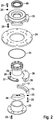
- FIG. 2 shows a further inventive rolling bearing 10 in an exploded view. That in the FIG. 2 Rolling bearing 10 substantially corresponds to that in the FIG. 1 shown bearings 10 so that reference is made in full to the above made executions and will be discussed below only the differences.
- An essential difference to that in the FIG. 1 shown rolling bearing 10 is that the second bearing ring 14 comprises a second outer bearing ring 36 and a separate second inner bearing ring 37. Both the second outer bearing ring 36 as well the second inner bearing ring 37 are each - as already in connection with the FIG. 1 to previously described - composed of several bearing ring segments.
- the first bearing ring 13 further comprises a first outer bearing ring 45 and a separate first inner bearing ring 46.
- the first outer bearing ring 45 and the separate first inner bearing ring 46 are each composed of a plurality of bearing ring segments.
- the first inner bearing ring 46 and the second inner bearing ring 37 are formed such that the tread formed by them surrounds the rolling elements 17 to more than 180 °.
- the first outer bearing ring 45 and the second outer bearing ring 36 can be disassembled, while the rolling elements 17 retained by the first inner bearing ring 46 and the second inner bearing ring 37 remain on the tread.
- the first and second inner bearing rings 46, 37 for example screwed together, are to be detached from one another and moved apart at least to the extent that the rolling elements 17 are released.
- rolling bearing 10 preferably includes no further inner ring member 30 and no mounting ring member 32 which would be arranged on this. Rather, the hydraulic clutch 29 is arranged directly in the inner ring member 26 frictionally. Further preferably, the second bearing body 12 comprises a cover hood 39 and a shaft seal 40 surrounding the axle 41.
- rolling elements 17 and / or the bearing rings 13, 14, 36, 37, 45, 46 made of plastic. More preferably, the rolling elements 17 are formed as balls. Alternatively, the rolling elements 17 are formed as cylindrical or tapered rollers.
- FIG. 3 is a plan view and a sectional view according to the section line AA of a portion of an exemplary Rundurgirvorraum shown in which the inventive Rolling 10 is installed.
- FIG. 3 is, inter alia, the fixed axis 41 and on the one hand in the FIG. 1 shown and described above rolling bearing 10 in the form of a thrust bearing 42 and in the FIG. 2 shown and previously described rolling bearing 10 according to the invention in the form of a radial bearing 43 shown.
- FIG. 4 shows the in the FIG. 3 shown part of the rotary device again in a perspective view.
- components of the rotary device from the prior art are well known, will be omitted to a further description of these components.
- the lubrication of the in the FIGS. 1 to 4 shown rolling bearing 10 according to the invention is preferably carried out by water as lubricants or lubricants.
- the rolling bearing 10 comprises further - not shown in the drawing - facilities, which are designed and arranged for introducing water between the rolling elements 17 and the first and second running surfaces 15, 16.
- the rolling bearing 10 further comprises discharge means, by means of which the introduced water from the inner storage area, in particular from the first and second running surfaces 15, 16 can be removed.
- discharge devices include, for example, a plurality of through-holes, which are arranged in the first and second bearing rings 13, 14. By means of these through holes can be drained water introduced.
- the water is provided with antibacterial additives which inhibit or prevent bacterial growth and thus effectively counteract otherwise possible microbial contamination of the rolling bearing.
Claims (10)
- Roulement (10), comprenantun premier et un deuxième corps de roulement (11, 12) agencés de manière à pouvoir tourner l'un par rapport à l'autre autour d'un axe (41),les corps de roulement (11, 12) comprenant une première et une deuxième bague de roulement (13, 14) avec des surfaces de roulement (15, 16) conçues et constituées tournées l'une vers l'autre et destinées à recevoir une pluralité de corps de roulement (17),les corps de roulement (17) étant agencés entre les surfaces de roulement (15, 16) des bagues de roulement (13, 14),lesdites bagues de roulement (13, 14) étant constituées en plusieurs parties au moyen de segments de bague de roulement (19, 20) détachables les uns des autres,le premier corps de roulement (11) étant conçu et constitué susceptible d'être ajusté dans le sens axial par rapport au deuxième corps de roulement (12),caractérisé en ce queles corps de roulement (11, 12) comprennent respectivement un premier élément de bague (23) et un deuxième élément de bague (24), les premiers segments de bague de roulement (19) étant agencés sur le premier élément de bague (23) et les deuxièmes segments de bague de roulement (20) sur le deuxième élément de bague (24), sur tout le tour et de manière détachable par des moyens de liaison (25), etle premier élément de bague (23) et/ou le deuxième élément de bague (24) est/sont constitué(s) au moins sensiblement en forme de disque, etle premier corps de roulement (11) est relié à un embrayage hydraulique (29) destiné à fixer le premier corps de roulement (11) sur l'axe (41).
- Roulement (10) selon la revendication 1, caractérisé en ce qu'un élément de bague intérieur (26) est agencé sur le premier élément de bague (23).
- Roulement (10) selon l'une quelconque des revendications 1 ou 2, caractérisé en ce que le premier corps de roulement (11) comprend l'élément de bague intérieur (26), les surfaces de paroi intérieure (27) des premiers segments de bague de roulement (19) venant épouser de manière solidaire la surface de paroi extérieure (28) de l'élément de bague intérieur (26).
- Roulement (10) selon l'une quelconque des revendications 1 à 3, caractérisé en ce que le premier corps de roulement (11) comprend un autre élément de bague intérieur (30), l'autre élément de bague intérieur (30) étant agencé de manière détachable sur l'élément de bague intérieur (26).
- Roulement (10) selon la revendication 4, caractérisé en ce qu'un élément de bague de montage (32), doté d'une cavité axiale (33) destinée à recevoir l'embrayage hydraulique (29), est agencé sur l'autre élément de bague intérieur (30), l'élément de bague de montage (32) étant relié à l'autre élément de bague intérieur (30) par au moins deux entretoises (34).
- Roulement (10) selon l'une quelconque des revendications 1 à 5, caractérisé en ce que la première bague de roulement (13) comprend une première bague de roulement extérieure (45) et une première bague de roulement intérieure (46) séparée.
- Roulement (10) selon l'une quelconque des revendications 1 à 6, caractérisé en ce que la deuxième bague de roulement (14) comprend une deuxième bague de roulement extérieure (36) et une deuxième bague de roulement intérieure (37) séparée.
- Roulement (10) selon l'une quelconque des revendications 1 à 7, caractérisé en ce que les corps de roulement (17) et/ou les bagues de roulement (12, 13, 36, 37, 45, 46) sont en matière plastique.
- Roulement (10) selon l'une quelconque des revendications 1 à 8, caractérisé en ce que les corps de roulement (17) sont des billes.
- Dispositif tournant comprenant un axe fixe (41) et un carrousel agencé de manière à pouvoir tourner autour de l'axe fixe (41), destiné à recevoir des articles à traiter en provenance de l'industrie de traitement des poissons et de la viande, caractérisé en ce que le carrousel est agencé sur l'axe fixe (41) par au moins un roulement (10) selon l'une quelconque des revendications 1 à 9, de manière à pouvoir tourner.
Priority Applications (1)
| Application Number | Priority Date | Filing Date | Title |
|---|---|---|---|
| PL13763050T PL2898232T3 (pl) | 2012-09-19 | 2013-09-16 | Łożysko toczne i urządzenie obrotowe z łożyskiem tocznym |
Applications Claiming Priority (2)
| Application Number | Priority Date | Filing Date | Title |
|---|---|---|---|
| DE102012108819.5A DE102012108819A1 (de) | 2012-09-19 | 2012-09-19 | Wälzlager und Rundläufervorrichtung mit Wälzlager |
| PCT/EP2013/069147 WO2014044634A1 (fr) | 2012-09-19 | 2013-09-16 | Roulement et dispositif tournant à roulement |
Publications (2)
| Publication Number | Publication Date |
|---|---|
| EP2898232A1 EP2898232A1 (fr) | 2015-07-29 |
| EP2898232B1 true EP2898232B1 (fr) | 2019-06-05 |
Family
ID=49209357
Family Applications (1)
| Application Number | Title | Priority Date | Filing Date |
|---|---|---|---|
| EP13763050.5A Active EP2898232B1 (fr) | 2012-09-19 | 2013-09-16 | Roulement et dispositif tournant à roulement |
Country Status (16)
| Country | Link |
|---|---|
| US (1) | US9587677B2 (fr) |
| EP (1) | EP2898232B1 (fr) |
| JP (1) | JP6067122B2 (fr) |
| KR (1) | KR101727001B1 (fr) |
| CN (1) | CN104641135B (fr) |
| BR (1) | BR112015005854B1 (fr) |
| CA (1) | CA2884141C (fr) |
| DE (1) | DE102012108819A1 (fr) |
| DK (1) | DK2898232T3 (fr) |
| ES (1) | ES2738824T3 (fr) |
| IL (1) | IL237709A0 (fr) |
| IN (1) | IN2015DN02365A (fr) |
| MY (1) | MY175058A (fr) |
| PL (1) | PL2898232T3 (fr) |
| RU (1) | RU2600973C1 (fr) |
| WO (1) | WO2014044634A1 (fr) |
Families Citing this family (4)
| Publication number | Priority date | Publication date | Assignee | Title |
|---|---|---|---|---|
| CN109099056B (zh) * | 2018-09-21 | 2020-05-05 | 浙江机电职业技术学院 | 一种双向剖分式平面轴承及其装配方法 |
| CN108980200B (zh) * | 2018-09-21 | 2020-05-05 | 浙江机电职业技术学院 | 一种剖分式平面轴承及其装配方法 |
| US11447927B2 (en) * | 2019-09-03 | 2022-09-20 | Caterpillar Inc. | Support assembly for a grading machine |
| CN112983973B (zh) * | 2021-02-22 | 2023-06-16 | 蚌埠市昊德汽车轴承有限责任公司 | 一种可更换的预紧弹簧圆锥滚子轴承 |
Citations (1)
| Publication number | Priority date | Publication date | Assignee | Title |
|---|---|---|---|---|
| EP1426639A1 (fr) * | 2002-12-05 | 2004-06-09 | Ab Skf | Procédé de montage d'un roulement à deux rangées de rouleaux coniques avec des bagues en plusieurs pièces dans une éolienne |
Family Cites Families (29)
| Publication number | Priority date | Publication date | Assignee | Title |
|---|---|---|---|---|
| US1071295A (en) * | 1913-08-26 | Paul Bruehl | Ball-bearing. | |
| DE1073248B (de) * | 1960-01-14 | Robert Zeuzem Frankfurt/M Fritz | Radial geteiltes Rollen oder Kugellager fur eingebaute gekröpfte Wellen | |
| GB191124655A (en) * | 1911-11-06 | 1912-06-13 | Walther Schutt | Improvements in and relating to Ball Bearings. |
| US1644611A (en) * | 1925-02-28 | 1927-10-04 | H Dux Company Inc Dr | Ball bearing |
| US1908474A (en) * | 1930-06-12 | 1933-05-09 | Hessbright Mfg Company | Connected bearing |
| DE903154C (de) * | 1951-11-15 | 1954-02-01 | Ladislav Karpisek | Zerlegbares Waelzlager |
| DE959076C (de) * | 1953-12-11 | 1957-02-28 | Eisen & Stahlind Ag | Verfahren zum Fertigen von vergueteten Segmenten kreisfoermiger Kugel- oder Rollenbahnen, insbesondere fuer Schwenkwerke von Baggern, Kranen od. dgl. |
| US3888357A (en) * | 1972-11-15 | 1975-06-10 | Caterpillar Tractor Co | Swing bearing with bolt-on segmented gear |
| DE3112303C2 (de) | 1981-03-28 | 1987-10-01 | FAG Kugelfischer Georg Schäfer KGaA, 8720 Schweinfurt | In Umfangsrichtung geteilter Käfig für ein zweireihiges Pendelrollenlager |
| JPS5853919U (ja) * | 1981-10-09 | 1983-04-12 | 日亜精密工業株式会社 | プラスチツク製ベアリング |
| JPS60208625A (ja) | 1984-03-30 | 1985-10-21 | Houriyou Sangyo Kk | 割軸受 |
| JPS6124819A (ja) * | 1984-07-13 | 1986-02-03 | Chubu Bearing Seisakusho:Kk | 合成樹脂製軸受 |
| US4622860A (en) * | 1985-06-24 | 1986-11-18 | Dresser Industries, Inc. | Method and apparatus for swing gear and bearing assembly for power mining shovel |
| JPS6213813A (ja) * | 1985-07-11 | 1987-01-22 | Mitsubishi Electric Corp | ころ軸受装置 |
| JPH06208625A (ja) * | 1993-01-11 | 1994-07-26 | Canon Inc | 画像処理方法及び装置 |
| RU2085772C1 (ru) | 1994-12-23 | 1997-07-27 | Петр Петрович Гиляров | Подшипник качения |
| US5599110A (en) * | 1995-06-07 | 1997-02-04 | Airlock, Incorporated | Bearing for a pressurized protective suit |
| CN2382886Y (zh) | 1999-08-13 | 2000-06-14 | 刘生万 | 剖分式滚动轴承 |
| DE202004007831U1 (de) * | 2004-05-14 | 2004-07-22 | Ab Skf | Mehrreihiges Wälzlager für eine Windenergieanlage |
| JP4438511B2 (ja) * | 2004-05-26 | 2010-03-24 | 株式会社ジェイテクト | 二つ割り外輪、それを用いた二つ割りころ軸受 |
| DE102004058905B4 (de) * | 2004-12-07 | 2010-02-18 | Aktiebolaget Skf | Wälzlager mit segmentierten Lagerringen |
| CN200985951Y (zh) | 2006-12-05 | 2007-12-05 | 瓦房店东旭非标准轴承集团有限公司 | 剖分式推力圆锥滚子轴承 |
| DE102007062145A1 (de) | 2007-12-21 | 2009-06-25 | Schaeffler Kg | Lageranordnung |
| DE102008024055A1 (de) * | 2008-05-16 | 2009-11-19 | Schaeffler Kg | Lagerring und Lager mit funktionsbezogenem Werkstoffverbund |
| CN101852246B (zh) * | 2010-05-12 | 2011-08-17 | 湖北工业大学 | 循环滚子剖分式轴承 |
| DE102010048479B4 (de) * | 2010-10-14 | 2014-07-10 | Schaeffler Technologies Gmbh & Co. Kg | Axiallageranordnung |
| CN201884473U (zh) | 2010-12-22 | 2011-06-29 | 王金领 | 曲轴连杆颈的分体式滚动轴承 |
| JP5701145B2 (ja) * | 2011-05-13 | 2015-04-15 | 株式会社椿本チエイン | 環状軌道輪モジュール及びアキシャルローラベアリング |
| DE102012206667B4 (de) * | 2012-04-23 | 2015-04-02 | Schaeffler Technologies Gmbh & Co. Kg | Axial-Radiallager |
-
2012
- 2012-09-19 DE DE102012108819.5A patent/DE102012108819A1/de not_active Ceased
-
2013
- 2013-09-16 CA CA2884141A patent/CA2884141C/fr active Active
- 2013-09-16 DK DK13763050.5T patent/DK2898232T3/da active
- 2013-09-16 US US14/427,606 patent/US9587677B2/en active Active
- 2013-09-16 MY MYPI2015000678A patent/MY175058A/en unknown
- 2013-09-16 RU RU2015109370/11A patent/RU2600973C1/ru active
- 2013-09-16 PL PL13763050T patent/PL2898232T3/pl unknown
- 2013-09-16 KR KR1020157006809A patent/KR101727001B1/ko active IP Right Grant
- 2013-09-16 EP EP13763050.5A patent/EP2898232B1/fr active Active
- 2013-09-16 WO PCT/EP2013/069147 patent/WO2014044634A1/fr active Application Filing
- 2013-09-16 BR BR112015005854-0A patent/BR112015005854B1/pt active IP Right Grant
- 2013-09-16 CN CN201380048926.1A patent/CN104641135B/zh active Active
- 2013-09-16 ES ES13763050T patent/ES2738824T3/es active Active
- 2013-09-16 JP JP2015532379A patent/JP6067122B2/ja active Active
-
2015
- 2015-03-12 IL IL237709A patent/IL237709A0/en unknown
- 2015-03-23 IN IN2365DEN2015 patent/IN2015DN02365A/en unknown
Patent Citations (1)
| Publication number | Priority date | Publication date | Assignee | Title |
|---|---|---|---|---|
| EP1426639A1 (fr) * | 2002-12-05 | 2004-06-09 | Ab Skf | Procédé de montage d'un roulement à deux rangées de rouleaux coniques avec des bagues en plusieurs pièces dans une éolienne |
Also Published As
| Publication number | Publication date |
|---|---|
| PL2898232T3 (pl) | 2019-11-29 |
| DE102012108819A1 (de) | 2014-03-20 |
| EP2898232A1 (fr) | 2015-07-29 |
| US20150247531A1 (en) | 2015-09-03 |
| CA2884141A1 (fr) | 2014-03-27 |
| WO2014044634A1 (fr) | 2014-03-27 |
| JP2015529316A (ja) | 2015-10-05 |
| BR112015005854B1 (pt) | 2021-09-08 |
| JP6067122B2 (ja) | 2017-01-25 |
| BR112015005854A2 (pt) | 2017-07-04 |
| KR20150046156A (ko) | 2015-04-29 |
| US9587677B2 (en) | 2017-03-07 |
| IN2015DN02365A (fr) | 2015-09-04 |
| DK2898232T3 (da) | 2019-08-26 |
| IL237709A0 (en) | 2015-05-31 |
| CN104641135B (zh) | 2017-06-13 |
| CN104641135A (zh) | 2015-05-20 |
| KR101727001B1 (ko) | 2017-04-14 |
| MY175058A (en) | 2020-06-04 |
| RU2600973C1 (ru) | 2016-10-27 |
| CA2884141C (fr) | 2017-08-01 |
| ES2738824T3 (es) | 2020-01-27 |
Similar Documents
| Publication | Publication Date | Title |
|---|---|---|
| DE3805350C2 (fr) | ||
| EP2874805B1 (fr) | Rouleau presseur | |
| EP2233760A1 (fr) | Palier à roulement à deux rangées lubrifié par de la graisse et système de stockage doté d'un tel palier à roulement et d'un dispositif de lubrification | |
| EP2898232B1 (fr) | Roulement et dispositif tournant à roulement | |
| EP1668263B1 (fr) | Ensemble support rotatif d'un corps rotatif | |
| DE102010036093A1 (de) | Lagerelement eines Ruderschaftlagers | |
| DE2032542A1 (de) | Aufweitbarer Wickeldorn | |
| DE3736435C2 (de) | Mischerwellen-Dichtung und -Lagerung für Mischbehälter von Betonmischmaschinen | |
| DE2227412A1 (de) | Anordnung zur lagerung eines laufringes auf dem mantel eines drehrohres | |
| DE102008000204A1 (de) | Lagerungen für einen Zylinder einer Rotationsdruckmaschine | |
| DE4225810C2 (de) | Falzzylinder | |
| DE2515200C2 (de) | Dichtvorrichtung für die Lager der Tragwellen von fliegend und auswechselbar angeordneten Walzscheiben | |
| DE10033894A1 (de) | Demontagevorrichtung für ein selbsteinstellendes Lager | |
| DE2921977A1 (de) | Wellenantriebselement | |
| DE102007029548B3 (de) | Formwerkzeug zum spanlosen Bearbeiten langgestreckter Werkstücke | |
| WO2017125529A1 (fr) | Rouleau de guidage de produit filé pour le guidage d'un produit filé métallique dans une installation de coulée continue | |
| EP0358790A1 (fr) | Système de broyage | |
| WO2009059590A2 (fr) | Palier lisse à garniture de glissement interchangeable | |
| DE10144974B4 (de) | Walzgerüst zum Walzen von stab- oder rohrförmigem Gut | |
| EP3091647B1 (fr) | Unite d'entrainement d'un agitateur et agitateur | |
| DE19509768C2 (de) | Lager | |
| EP0721828A2 (fr) | Camion-bétonnière | |
| DE102008027494A1 (de) | Mehrteilige Walze | |
| DE19903339A1 (de) | Gleitlager mit axial teilbaren Lagerschalenhälften | |
| AT246548B (de) | Scheibenmühle |
Legal Events
| Date | Code | Title | Description |
|---|---|---|---|
| PUAI | Public reference made under article 153(3) epc to a published international application that has entered the european phase |
Free format text: ORIGINAL CODE: 0009012 |
|
| 17P | Request for examination filed |
Effective date: 20150416 |
|
| AK | Designated contracting states |
Kind code of ref document: A1 Designated state(s): AL AT BE BG CH CY CZ DE DK EE ES FI FR GB GR HR HU IE IS IT LI LT LU LV MC MK MT NL NO PL PT RO RS SE SI SK SM TR |
|
| AX | Request for extension of the european patent |
Extension state: BA ME |
|
| DAX | Request for extension of the european patent (deleted) | ||
| 17Q | First examination report despatched |
Effective date: 20160718 |
|
| STAA | Information on the status of an ep patent application or granted ep patent |
Free format text: STATUS: EXAMINATION IS IN PROGRESS |
|
| GRAP | Despatch of communication of intention to grant a patent |
Free format text: ORIGINAL CODE: EPIDOSNIGR1 |
|
| STAA | Information on the status of an ep patent application or granted ep patent |
Free format text: STATUS: GRANT OF PATENT IS INTENDED |
|
| INTG | Intention to grant announced |
Effective date: 20181129 |
|
| GRAS | Grant fee paid |
Free format text: ORIGINAL CODE: EPIDOSNIGR3 |
|
| GRAJ | Information related to disapproval of communication of intention to grant by the applicant or resumption of examination proceedings by the epo deleted |
Free format text: ORIGINAL CODE: EPIDOSDIGR1 |
|
| GRAL | Information related to payment of fee for publishing/printing deleted |
Free format text: ORIGINAL CODE: EPIDOSDIGR3 |
|
| STAA | Information on the status of an ep patent application or granted ep patent |
Free format text: STATUS: EXAMINATION IS IN PROGRESS |
|
| GRAR | Information related to intention to grant a patent recorded |
Free format text: ORIGINAL CODE: EPIDOSNIGR71 |
|
| STAA | Information on the status of an ep patent application or granted ep patent |
Free format text: STATUS: GRANT OF PATENT IS INTENDED |
|
| GRAA | (expected) grant |
Free format text: ORIGINAL CODE: 0009210 |
|
| STAA | Information on the status of an ep patent application or granted ep patent |
Free format text: STATUS: THE PATENT HAS BEEN GRANTED |
|
| INTC | Intention to grant announced (deleted) | ||
| INTG | Intention to grant announced |
Effective date: 20190424 |
|
| AK | Designated contracting states |
Kind code of ref document: B1 Designated state(s): AL AT BE BG CH CY CZ DE DK EE ES FI FR GB GR HR HU IE IS IT LI LT LU LV MC MK MT NL NO PL PT RO RS SE SI SK SM TR |
|
| REG | Reference to a national code |
Ref country code: GB Ref legal event code: FG4D Free format text: NOT ENGLISH |
|
| REG | Reference to a national code |
Ref country code: CH Ref legal event code: EP |
|
| REG | Reference to a national code |
Ref country code: AT Ref legal event code: REF Ref document number: 1140290 Country of ref document: AT Kind code of ref document: T Effective date: 20190615 |
|
| REG | Reference to a national code |
Ref country code: IE Ref legal event code: FG4D Free format text: LANGUAGE OF EP DOCUMENT: GERMAN |
|
| REG | Reference to a national code |
Ref country code: DE Ref legal event code: R096 Ref document number: 502013012951 Country of ref document: DE |
|
| REG | Reference to a national code |
Ref country code: DK Ref legal event code: T3 Effective date: 20190822 |
|
| REG | Reference to a national code |
Ref country code: NL Ref legal event code: FP |
|
| REG | Reference to a national code |
Ref country code: LT Ref legal event code: MG4D |
|
| PG25 | Lapsed in a contracting state [announced via postgrant information from national office to epo] |
Ref country code: HR Free format text: LAPSE BECAUSE OF FAILURE TO SUBMIT A TRANSLATION OF THE DESCRIPTION OR TO PAY THE FEE WITHIN THE PRESCRIBED TIME-LIMIT Effective date: 20190605 Ref country code: NO Free format text: LAPSE BECAUSE OF FAILURE TO SUBMIT A TRANSLATION OF THE DESCRIPTION OR TO PAY THE FEE WITHIN THE PRESCRIBED TIME-LIMIT Effective date: 20190905 Ref country code: SE Free format text: LAPSE BECAUSE OF FAILURE TO SUBMIT A TRANSLATION OF THE DESCRIPTION OR TO PAY THE FEE WITHIN THE PRESCRIBED TIME-LIMIT Effective date: 20190605 Ref country code: FI Free format text: LAPSE BECAUSE OF FAILURE TO SUBMIT A TRANSLATION OF THE DESCRIPTION OR TO PAY THE FEE WITHIN THE PRESCRIBED TIME-LIMIT Effective date: 20190605 Ref country code: AL Free format text: LAPSE BECAUSE OF FAILURE TO SUBMIT A TRANSLATION OF THE DESCRIPTION OR TO PAY THE FEE WITHIN THE PRESCRIBED TIME-LIMIT Effective date: 20190605 Ref country code: LT Free format text: LAPSE BECAUSE OF FAILURE TO SUBMIT A TRANSLATION OF THE DESCRIPTION OR TO PAY THE FEE WITHIN THE PRESCRIBED TIME-LIMIT Effective date: 20190605 |
|
| PG25 | Lapsed in a contracting state [announced via postgrant information from national office to epo] |
Ref country code: BG Free format text: LAPSE BECAUSE OF FAILURE TO SUBMIT A TRANSLATION OF THE DESCRIPTION OR TO PAY THE FEE WITHIN THE PRESCRIBED TIME-LIMIT Effective date: 20190905 Ref country code: RS Free format text: LAPSE BECAUSE OF FAILURE TO SUBMIT A TRANSLATION OF THE DESCRIPTION OR TO PAY THE FEE WITHIN THE PRESCRIBED TIME-LIMIT Effective date: 20190605 Ref country code: GR Free format text: LAPSE BECAUSE OF FAILURE TO SUBMIT A TRANSLATION OF THE DESCRIPTION OR TO PAY THE FEE WITHIN THE PRESCRIBED TIME-LIMIT Effective date: 20190906 Ref country code: LV Free format text: LAPSE BECAUSE OF FAILURE TO SUBMIT A TRANSLATION OF THE DESCRIPTION OR TO PAY THE FEE WITHIN THE PRESCRIBED TIME-LIMIT Effective date: 20190605 |
|
| REG | Reference to a national code |
Ref country code: ES Ref legal event code: FG2A Ref document number: 2738824 Country of ref document: ES Kind code of ref document: T3 Effective date: 20200127 |
|
| PG25 | Lapsed in a contracting state [announced via postgrant information from national office to epo] |
Ref country code: SK Free format text: LAPSE BECAUSE OF FAILURE TO SUBMIT A TRANSLATION OF THE DESCRIPTION OR TO PAY THE FEE WITHIN THE PRESCRIBED TIME-LIMIT Effective date: 20190605 Ref country code: RO Free format text: LAPSE BECAUSE OF FAILURE TO SUBMIT A TRANSLATION OF THE DESCRIPTION OR TO PAY THE FEE WITHIN THE PRESCRIBED TIME-LIMIT Effective date: 20190605 Ref country code: CZ Free format text: LAPSE BECAUSE OF FAILURE TO SUBMIT A TRANSLATION OF THE DESCRIPTION OR TO PAY THE FEE WITHIN THE PRESCRIBED TIME-LIMIT Effective date: 20190605 Ref country code: EE Free format text: LAPSE BECAUSE OF FAILURE TO SUBMIT A TRANSLATION OF THE DESCRIPTION OR TO PAY THE FEE WITHIN THE PRESCRIBED TIME-LIMIT Effective date: 20190605 Ref country code: PT Free format text: LAPSE BECAUSE OF FAILURE TO SUBMIT A TRANSLATION OF THE DESCRIPTION OR TO PAY THE FEE WITHIN THE PRESCRIBED TIME-LIMIT Effective date: 20191007 |
|
| PG25 | Lapsed in a contracting state [announced via postgrant information from national office to epo] |
Ref country code: SM Free format text: LAPSE BECAUSE OF FAILURE TO SUBMIT A TRANSLATION OF THE DESCRIPTION OR TO PAY THE FEE WITHIN THE PRESCRIBED TIME-LIMIT Effective date: 20190605 Ref country code: IT Free format text: LAPSE BECAUSE OF FAILURE TO SUBMIT A TRANSLATION OF THE DESCRIPTION OR TO PAY THE FEE WITHIN THE PRESCRIBED TIME-LIMIT Effective date: 20190605 |
|
| REG | Reference to a national code |
Ref country code: DE Ref legal event code: R097 Ref document number: 502013012951 Country of ref document: DE |
|
| PG25 | Lapsed in a contracting state [announced via postgrant information from national office to epo] |
Ref country code: TR Free format text: LAPSE BECAUSE OF FAILURE TO SUBMIT A TRANSLATION OF THE DESCRIPTION OR TO PAY THE FEE WITHIN THE PRESCRIBED TIME-LIMIT Effective date: 20190605 |
|
| PLBE | No opposition filed within time limit |
Free format text: ORIGINAL CODE: 0009261 |
|
| STAA | Information on the status of an ep patent application or granted ep patent |
Free format text: STATUS: NO OPPOSITION FILED WITHIN TIME LIMIT |
|
| 26N | No opposition filed |
Effective date: 20200306 |
|
| PG25 | Lapsed in a contracting state [announced via postgrant information from national office to epo] |
Ref country code: SI Free format text: LAPSE BECAUSE OF FAILURE TO SUBMIT A TRANSLATION OF THE DESCRIPTION OR TO PAY THE FEE WITHIN THE PRESCRIBED TIME-LIMIT Effective date: 20190605 Ref country code: MC Free format text: LAPSE BECAUSE OF FAILURE TO SUBMIT A TRANSLATION OF THE DESCRIPTION OR TO PAY THE FEE WITHIN THE PRESCRIBED TIME-LIMIT Effective date: 20190605 |
|
| REG | Reference to a national code |
Ref country code: CH Ref legal event code: PL |
|
| PG25 | Lapsed in a contracting state [announced via postgrant information from national office to epo] |
Ref country code: CH Free format text: LAPSE BECAUSE OF NON-PAYMENT OF DUE FEES Effective date: 20190930 Ref country code: IE Free format text: LAPSE BECAUSE OF NON-PAYMENT OF DUE FEES Effective date: 20190916 Ref country code: LI Free format text: LAPSE BECAUSE OF NON-PAYMENT OF DUE FEES Effective date: 20190930 Ref country code: LU Free format text: LAPSE BECAUSE OF NON-PAYMENT OF DUE FEES Effective date: 20190916 |
|
| REG | Reference to a national code |
Ref country code: BE Ref legal event code: MM Effective date: 20190930 |
|
| PG25 | Lapsed in a contracting state [announced via postgrant information from national office to epo] |
Ref country code: BE Free format text: LAPSE BECAUSE OF NON-PAYMENT OF DUE FEES Effective date: 20190930 |
|
| PG25 | Lapsed in a contracting state [announced via postgrant information from national office to epo] |
Ref country code: FR Free format text: LAPSE BECAUSE OF NON-PAYMENT OF DUE FEES Effective date: 20190930 |
|
| REG | Reference to a national code |
Ref country code: AT Ref legal event code: MM01 Ref document number: 1140290 Country of ref document: AT Kind code of ref document: T Effective date: 20190916 |
|
| PG25 | Lapsed in a contracting state [announced via postgrant information from national office to epo] |
Ref country code: AT Free format text: LAPSE BECAUSE OF NON-PAYMENT OF DUE FEES Effective date: 20190916 |
|
| PG25 | Lapsed in a contracting state [announced via postgrant information from national office to epo] |
Ref country code: CY Free format text: LAPSE BECAUSE OF FAILURE TO SUBMIT A TRANSLATION OF THE DESCRIPTION OR TO PAY THE FEE WITHIN THE PRESCRIBED TIME-LIMIT Effective date: 20190605 |
|
| PG25 | Lapsed in a contracting state [announced via postgrant information from national office to epo] |
Ref country code: MT Free format text: LAPSE BECAUSE OF FAILURE TO SUBMIT A TRANSLATION OF THE DESCRIPTION OR TO PAY THE FEE WITHIN THE PRESCRIBED TIME-LIMIT Effective date: 20190605 Ref country code: HU Free format text: LAPSE BECAUSE OF FAILURE TO SUBMIT A TRANSLATION OF THE DESCRIPTION OR TO PAY THE FEE WITHIN THE PRESCRIBED TIME-LIMIT; INVALID AB INITIO Effective date: 20130916 |
|
| PG25 | Lapsed in a contracting state [announced via postgrant information from national office to epo] |
Ref country code: MK Free format text: LAPSE BECAUSE OF FAILURE TO SUBMIT A TRANSLATION OF THE DESCRIPTION OR TO PAY THE FEE WITHIN THE PRESCRIBED TIME-LIMIT Effective date: 20190605 |
|
| P01 | Opt-out of the competence of the unified patent court (upc) registered |
Effective date: 20230517 |
|
| PGFP | Annual fee paid to national office [announced via postgrant information from national office to epo] |
Ref country code: NL Payment date: 20230920 Year of fee payment: 11 Ref country code: GB Payment date: 20230921 Year of fee payment: 11 |
|
| PGFP | Annual fee paid to national office [announced via postgrant information from national office to epo] |
Ref country code: PL Payment date: 20230711 Year of fee payment: 11 Ref country code: IS Payment date: 20230718 Year of fee payment: 11 Ref country code: DK Payment date: 20230921 Year of fee payment: 11 Ref country code: DE Payment date: 20230919 Year of fee payment: 11 |
|
| PGFP | Annual fee paid to national office [announced via postgrant information from national office to epo] |
Ref country code: ES Payment date: 20231019 Year of fee payment: 11 |