EP2898232B1 - Rolling bearing, and rotary device with rolling bearing - Google Patents
Rolling bearing, and rotary device with rolling bearing Download PDFInfo
- Publication number
- EP2898232B1 EP2898232B1 EP13763050.5A EP13763050A EP2898232B1 EP 2898232 B1 EP2898232 B1 EP 2898232B1 EP 13763050 A EP13763050 A EP 13763050A EP 2898232 B1 EP2898232 B1 EP 2898232B1
- Authority
- EP
- European Patent Office
- Prior art keywords
- bearing
- ring
- ring element
- rolling
- rolling bearing
- Prior art date
- Legal status (The legal status is an assumption and is not a legal conclusion. Google has not performed a legal analysis and makes no representation as to the accuracy of the status listed.)
- Active
Links
- 238000005096 rolling process Methods 0.000 title claims description 74
- 230000008878 coupling Effects 0.000 claims description 6
- 238000010168 coupling process Methods 0.000 claims description 6
- 238000005859 coupling reaction Methods 0.000 claims description 6
- 241000251468 Actinopterygii Species 0.000 claims description 5
- 235000013372 meat Nutrition 0.000 claims description 5
- 229920003023 plastic Polymers 0.000 claims description 5
- 239000004033 plastic Substances 0.000 claims description 5
- 239000000463 material Substances 0.000 claims description 2
- 230000002093 peripheral effect Effects 0.000 claims 2
- XLYOFNOQVPJJNP-UHFFFAOYSA-N water Substances O XLYOFNOQVPJJNP-UHFFFAOYSA-N 0.000 description 8
- 238000004140 cleaning Methods 0.000 description 6
- 239000000314 lubricant Substances 0.000 description 6
- 235000013305 food Nutrition 0.000 description 5
- 238000012423 maintenance Methods 0.000 description 5
- 238000007689 inspection Methods 0.000 description 3
- 239000007788 liquid Substances 0.000 description 3
- 239000000654 additive Substances 0.000 description 2
- 230000000844 anti-bacterial effect Effects 0.000 description 2
- 230000001580 bacterial effect Effects 0.000 description 2
- 239000012530 fluid Substances 0.000 description 2
- 238000005461 lubrication Methods 0.000 description 2
- 239000002184 metal Substances 0.000 description 2
- 241000894006 Bacteria Species 0.000 description 1
- 229910000831 Steel Inorganic materials 0.000 description 1
- 238000011109 contamination Methods 0.000 description 1
- 238000001816 cooling Methods 0.000 description 1
- 230000001419 dependent effect Effects 0.000 description 1
- 230000000249 desinfective effect Effects 0.000 description 1
- 230000003670 easy-to-clean Effects 0.000 description 1
- 230000000694 effects Effects 0.000 description 1
- 238000009434 installation Methods 0.000 description 1
- JEIPFZHSYJVQDO-UHFFFAOYSA-N iron(III) oxide Inorganic materials O=[Fe]O[Fe]=O JEIPFZHSYJVQDO-UHFFFAOYSA-N 0.000 description 1
- 230000001050 lubricating effect Effects 0.000 description 1
- 238000004519 manufacturing process Methods 0.000 description 1
- 230000000813 microbial effect Effects 0.000 description 1
- 230000003287 optical effect Effects 0.000 description 1
- 230000000717 retained effect Effects 0.000 description 1
- 238000007789 sealing Methods 0.000 description 1
- 239000010959 steel Substances 0.000 description 1
- 238000003860 storage Methods 0.000 description 1
Images


Classifications
-
- F—MECHANICAL ENGINEERING; LIGHTING; HEATING; WEAPONS; BLASTING
- F16—ENGINEERING ELEMENTS AND UNITS; GENERAL MEASURES FOR PRODUCING AND MAINTAINING EFFECTIVE FUNCTIONING OF MACHINES OR INSTALLATIONS; THERMAL INSULATION IN GENERAL
- F16C—SHAFTS; FLEXIBLE SHAFTS; ELEMENTS OR CRANKSHAFT MECHANISMS; ROTARY BODIES OTHER THAN GEARING ELEMENTS; BEARINGS
- F16C19/00—Bearings with rolling contact, for exclusively rotary movement
- F16C19/02—Bearings with rolling contact, for exclusively rotary movement with bearing balls essentially of the same size in one or more circular rows
- F16C19/10—Bearings with rolling contact, for exclusively rotary movement with bearing balls essentially of the same size in one or more circular rows for axial load mainly
-
- F—MECHANICAL ENGINEERING; LIGHTING; HEATING; WEAPONS; BLASTING
- F16—ENGINEERING ELEMENTS AND UNITS; GENERAL MEASURES FOR PRODUCING AND MAINTAINING EFFECTIVE FUNCTIONING OF MACHINES OR INSTALLATIONS; THERMAL INSULATION IN GENERAL
- F16C—SHAFTS; FLEXIBLE SHAFTS; ELEMENTS OR CRANKSHAFT MECHANISMS; ROTARY BODIES OTHER THAN GEARING ELEMENTS; BEARINGS
- F16C33/00—Parts of bearings; Special methods for making bearings or parts thereof
- F16C33/30—Parts of ball or roller bearings
- F16C33/58—Raceways; Race rings
- F16C33/60—Raceways; Race rings divided or split, e.g. comprising two juxtaposed rings
-
- A—HUMAN NECESSITIES
- A22—BUTCHERING; MEAT TREATMENT; PROCESSING POULTRY OR FISH
- A22C—PROCESSING MEAT, POULTRY, OR FISH
- A22C17/00—Other devices for processing meat or bones
-
- F—MECHANICAL ENGINEERING; LIGHTING; HEATING; WEAPONS; BLASTING
- F16—ENGINEERING ELEMENTS AND UNITS; GENERAL MEASURES FOR PRODUCING AND MAINTAINING EFFECTIVE FUNCTIONING OF MACHINES OR INSTALLATIONS; THERMAL INSULATION IN GENERAL
- F16C—SHAFTS; FLEXIBLE SHAFTS; ELEMENTS OR CRANKSHAFT MECHANISMS; ROTARY BODIES OTHER THAN GEARING ELEMENTS; BEARINGS
- F16C19/00—Bearings with rolling contact, for exclusively rotary movement
- F16C19/02—Bearings with rolling contact, for exclusively rotary movement with bearing balls essentially of the same size in one or more circular rows
- F16C19/04—Bearings with rolling contact, for exclusively rotary movement with bearing balls essentially of the same size in one or more circular rows for radial load mainly
- F16C19/06—Bearings with rolling contact, for exclusively rotary movement with bearing balls essentially of the same size in one or more circular rows for radial load mainly with a single row or balls
-
- F—MECHANICAL ENGINEERING; LIGHTING; HEATING; WEAPONS; BLASTING
- F16—ENGINEERING ELEMENTS AND UNITS; GENERAL MEASURES FOR PRODUCING AND MAINTAINING EFFECTIVE FUNCTIONING OF MACHINES OR INSTALLATIONS; THERMAL INSULATION IN GENERAL
- F16C—SHAFTS; FLEXIBLE SHAFTS; ELEMENTS OR CRANKSHAFT MECHANISMS; ROTARY BODIES OTHER THAN GEARING ELEMENTS; BEARINGS
- F16C43/00—Assembling bearings
- F16C43/04—Assembling rolling-contact bearings
-
- F—MECHANICAL ENGINEERING; LIGHTING; HEATING; WEAPONS; BLASTING
- F16—ENGINEERING ELEMENTS AND UNITS; GENERAL MEASURES FOR PRODUCING AND MAINTAINING EFFECTIVE FUNCTIONING OF MACHINES OR INSTALLATIONS; THERMAL INSULATION IN GENERAL
- F16C—SHAFTS; FLEXIBLE SHAFTS; ELEMENTS OR CRANKSHAFT MECHANISMS; ROTARY BODIES OTHER THAN GEARING ELEMENTS; BEARINGS
- F16C19/00—Bearings with rolling contact, for exclusively rotary movement
- F16C19/54—Systems consisting of a plurality of bearings with rolling friction
- F16C19/545—Systems comprising at least one rolling bearing for radial load in combination with at least one rolling bearing for axial load
-
- F—MECHANICAL ENGINEERING; LIGHTING; HEATING; WEAPONS; BLASTING
- F16—ENGINEERING ELEMENTS AND UNITS; GENERAL MEASURES FOR PRODUCING AND MAINTAINING EFFECTIVE FUNCTIONING OF MACHINES OR INSTALLATIONS; THERMAL INSULATION IN GENERAL
- F16C—SHAFTS; FLEXIBLE SHAFTS; ELEMENTS OR CRANKSHAFT MECHANISMS; ROTARY BODIES OTHER THAN GEARING ELEMENTS; BEARINGS
- F16C2226/00—Joining parts; Fastening; Assembling or mounting parts
- F16C2226/50—Positive connections
- F16C2226/60—Positive connections with threaded parts, e.g. bolt and nut connections
-
- F—MECHANICAL ENGINEERING; LIGHTING; HEATING; WEAPONS; BLASTING
- F16—ENGINEERING ELEMENTS AND UNITS; GENERAL MEASURES FOR PRODUCING AND MAINTAINING EFFECTIVE FUNCTIONING OF MACHINES OR INSTALLATIONS; THERMAL INSULATION IN GENERAL
- F16C—SHAFTS; FLEXIBLE SHAFTS; ELEMENTS OR CRANKSHAFT MECHANISMS; ROTARY BODIES OTHER THAN GEARING ELEMENTS; BEARINGS
- F16C2326/00—Articles relating to transporting
- F16C2326/58—Conveyor systems, e.g. rollers or bearings therefor
-
- F—MECHANICAL ENGINEERING; LIGHTING; HEATING; WEAPONS; BLASTING
- F16—ENGINEERING ELEMENTS AND UNITS; GENERAL MEASURES FOR PRODUCING AND MAINTAINING EFFECTIVE FUNCTIONING OF MACHINES OR INSTALLATIONS; THERMAL INSULATION IN GENERAL
- F16C—SHAFTS; FLEXIBLE SHAFTS; ELEMENTS OR CRANKSHAFT MECHANISMS; ROTARY BODIES OTHER THAN GEARING ELEMENTS; BEARINGS
- F16C33/00—Parts of bearings; Special methods for making bearings or parts thereof
- F16C33/30—Parts of ball or roller bearings
- F16C33/32—Balls
-
- F—MECHANICAL ENGINEERING; LIGHTING; HEATING; WEAPONS; BLASTING
- F16—ENGINEERING ELEMENTS AND UNITS; GENERAL MEASURES FOR PRODUCING AND MAINTAINING EFFECTIVE FUNCTIONING OF MACHINES OR INSTALLATIONS; THERMAL INSULATION IN GENERAL
- F16C—SHAFTS; FLEXIBLE SHAFTS; ELEMENTS OR CRANKSHAFT MECHANISMS; ROTARY BODIES OTHER THAN GEARING ELEMENTS; BEARINGS
- F16C33/00—Parts of bearings; Special methods for making bearings or parts thereof
- F16C33/30—Parts of ball or roller bearings
- F16C33/58—Raceways; Race rings
- F16C33/62—Selection of substances
-
- F—MECHANICAL ENGINEERING; LIGHTING; HEATING; WEAPONS; BLASTING
- F16—ENGINEERING ELEMENTS AND UNITS; GENERAL MEASURES FOR PRODUCING AND MAINTAINING EFFECTIVE FUNCTIONING OF MACHINES OR INSTALLATIONS; THERMAL INSULATION IN GENERAL
- F16C—SHAFTS; FLEXIBLE SHAFTS; ELEMENTS OR CRANKSHAFT MECHANISMS; ROTARY BODIES OTHER THAN GEARING ELEMENTS; BEARINGS
- F16C35/00—Rigid support of bearing units; Housings, e.g. caps, covers
- F16C35/04—Rigid support of bearing units; Housings, e.g. caps, covers in the case of ball or roller bearings
- F16C35/06—Mounting or dismounting of ball or roller bearings; Fixing them onto shaft or in housing
- F16C35/07—Fixing them on the shaft or housing with interposition of an element
- F16C35/073—Fixing them on the shaft or housing with interposition of an element between shaft and inner race ring
Definitions
- the present invention relates to a rolling bearing, such as in DE 10 2008 024 055 A1 .
- a rolling bearing such as in DE 10 2008 024 055 A1 .
- US Pat. No. 4,622,860 A1 and EP 1 426 639 A1 shown comprising a first and a second bearing body, which are arranged rotatably relative to each other about an axis, wherein the bearing bodies comprise first and second bearing rings facing each other and adapted to receive a plurality of rolling elements and arranged running surfaces, wherein the rolling elements between the running surfaces of the Bearing rings are arranged.
- the invention further relates to a rotary apparatus comprising a fixed axle and a carousel rotatably mounted about the fixed axle for receiving articles of the fish and meat processing industry to be processed.
- Such bearings are used in particular in machines and devices of the food processing industry, for example in the processing and production of articles of the fish and meat processing industry.
- the known rolling bearings generally consist of two bearing rings, for example in the form of axial disc-shaped bearing rings, between which rolling elements, for example in the form of rollers, needles, balls or cones are taken.
- the use of lubricants is usually unavoidable.
- the object is achieved by an arrangement with the features mentioned above in that the bearing rings are formed in several parts by means of detachable bearing ring segments.
- the rolling bearing according to the invention offers a number of advantages. Due to the multi-part bearing ring segments, the rolling bearing is to maintain a particularly simple way and wear parts, such as the bearing rings and / or the rolling elements can be replaced with little effort, without having to dismantle the entire camp. In particular, it is possible with the bearing according to the invention to dismantle only maintenance-requiring components of the bearing according to the invention for maintenance and / or replacement purposes, since due to the bearing rings formed from a plurality of detachable bearing ring segments, the individual bearing rings are removable after opening the bearing. The same applies to the assembly. On the other hand, the rolling bearing according to the invention offers further advantages from a hygienic point of view, since the bearing is particularly easy to clean due to the easy accessibility of the individual components.
- the invention is characterized in that the first bearing body is arranged and configured to be adjustable relative to the second bearing body in the axial direction.
- the invention is characterized in that the bearing bodies each comprise a first ring element and a second ring element, wherein the first bearing ring segments on the first ring element and the second bearing ring segments on the second ring element are arranged completely circumferentially by means of connecting means releasably.
- the ring elements serve as support elements to which the bearing ring segments are attached and assembled to the respective bearing rings.
- the ring elements serve at the same time as a mounting base to which further components to be rotatably mounted with respect to the axis can be arranged.
- the invention is further distinguished by the fact that the first ring element and / or the second ring element is at least substantially disc-shaped.
- the ring element thus provides the required mechanical stability to securely fix the bearing ring segments and at the same time has an advantageous effect due to a low overall height.
- the invention is characterized in that the first bearing body is connected to a hydraulic coupling for fastening the first bearing body to the axle.
- This offers the advantage that the first bearing body can be solved in a particularly simple manner by the hydraulic coupling in a particularly simple manner from the axis or, if necessary, can be arranged on this.
- the first bearing body comprises an inner ring element, wherein the inner circumferential surfaces of the first bearing ring segments rest positively on the outer circumferential surface of the inner ring member. Due to the positive engagement of the bearing ring segments can be positioned in a particularly simple manner during installation, since the position is predetermined at least in the radial direction by the inner ring member and is defined by this.
- the inner ring element is arranged on the first ring element.
- the inner ring element forms an inner cylinder, at one end of which the first ring element, preferably cohesively, is arranged.
- a further expedient embodiment of the invention is characterized in that the first bearing body comprises a further inner ring element, wherein the further inner ring element is detachably arranged on the inner ring element.
- the further inner ring element is a connecting element, by means of which further components of the first bearing body with the of the first ring element and the inner ring element existing lower first bearing body part are connected. Further can be moved by means of the releasable connection between the other inner ring member and the inner ring member, the first lower bearing body part relative to the other inner ring member in the axial direction, for example, to lower the lower bearing body part for maintenance, repair and / or cleaning purposes.
- a mounting ring with an axial recess for receiving the hydraulic clutch is arranged on the further inner ring element, wherein the mounting ring is connected by means of at least two transverse webs with the further inner ring element.
- a further advantageous embodiment of the invention is characterized in that the first bearing body is arranged and configured to be adjustable relative to the second bearing body in the axial direction.
- the first bearing ring comprises a first outer bearing ring and a separate first inner bearing ring, so that the first bearing ring not only comprises a plurality of bearing ring segments in the circumferential direction, but is divided into the first outer bearing ring and in the first inner bearing ring.
- the first outer bearing ring and the first inner bearing ring in turn each comprise a plurality of bearing ring segments.
- the second bearing ring comprises a second outer bearing ring and a separate second inner bearing ring.
- the second bearing ring not only comprises a plurality of bearing ring segments in the circumferential direction, but is divided into the second outer bearing ring and the second inner bearing ring.
- Both the second outer Bearing ring and the second inner bearing ring each comprise in turn several bearing ring segments.
- the rolling elements and / or the bearing rings made of plastic.
- This offers the advantage, in particular at low rotational speeds of less than 30 revolutions per minute, that no lubrication of the rolling bearing is necessary, which otherwise is problematic for reasons of hygiene in the food industry for many reasons.
- plastic parts are not susceptible to rust when water penetrates, in contrast to metal parts. It is therefore possible, for example, to use water or other liquids obtained in the processing of articles of the meat and fish processing industry in a device provided with the rolling bearing device according to the invention, at the same time to be used as a cooling or lubricating fluid in the rolling bearing according to the invention.
- the rolling elements are balls. Due to the low rolling friction of the balls rolling bearing according to the invention is so very smooth.
- the object is achieved by a rotary apparatus with the features mentioned above in that the carousel is rotatably arranged by means of at least one rolling bearing according to one of claims 1 to 9 on the fixed axis.
- the rolling bearing according to the invention is particularly easy to maintain and to repair and beyond optimal for use in an environment that makes high demands on hygiene. Therefore, the rolling bearing according to the invention is particularly suitable for use in rotary devices. Liquids produced during the processing of articles or products of the meat and fish processing industry are often contaminated with bacteria. Due to the previously described possibility of being able to clean the rolling bearing according to the invention in a particularly simple manner, the rolling bearing according to the invention is optimally equipped to meet the high requirements in the food sector in terms of hygiene.
- the rolling bearing 10 includes a first bearing body 11 and a second bearing body 12.
- the first bearing body 11 and the second bearing body 12 are to a - in the FIG. 1 not shown - axis 41 arranged rotatably relative to each other.
- the first bearing body 11 comprises a first bearing ring 13 and the second bearing body 12 has a second bearing ring 14.
- the first and second bearing rings 13, 14 have first running surfaces 15 and second running surfaces 16 which are designed and arranged to receive a plurality of rolling elements 17.
- the running surfaces 15, 16 are preferably designed corresponding to the geometry of the rolling bodies 17 such that the rolling bodies 17 arranged between the running surfaces 15, 16 are guided by the running surfaces 15, 16.
- the running surfaces 15, 16 are groove-shaped.
- the first and second bearing rings 13, 14 are shown in several parts, ie the bearing rings 13, 14 comprise a plurality of bearing ring segments 19, 20, namely the first bearing ring 13, the first bearing ring segments 19 and the second bearing ring 14, the second bearing ring segments 20, of which in the FIG. 1 for better clarity only one is shown.
- Each of the bearing rings 13, 14 preferably comprises at least two of the bearing ring segments 19, 20. More preferably, each of the bearing rings 13, 14 comprises four bearing ring segments 19, 20. Basically, any number of bearing ring segments 19, 20 greater than two is suitable.
- the bearing ring segments 19, 20 are formed such that they are arranged with their respective end faces 21, 22 to the respective other end face 21, 22 positively fitting. That in the FIG. 1 shown roller bearing 10 is designed and set up as a thrust bearing 42, so preferably for receiving acting in the direction of the axis 41 forces.
- the first bearing body 11 comprises a first ring element 23 and the second bearing body 12 a second ring element 24.
- At the ring elements 23, 24 are respectively the first and second bearing ring segments 19, 20, so the first bearing ring segments 19 on the first ring member 23 and the second bearing ring segment 20th arranged completely circumferentially on the second ring element 24.
- the bearing ring segments 19, 20 are detachably arranged on the respective ring elements 23, 24 by means of connecting means 25.
- connecting means 25 preferably threaded screws are used.
- bearing ring segments 19, 20 on their sides facing away from the running surfaces 15, 16 corresponding threaded bores for receiving the connecting means 25.
- the ring elements 23, 24 likewise have correspondingly positioned bores through which the threaded screws are guided and the ring elements 23, 24 are connected to the bearing ring segments 19, 20.
- the connection between the bearing ring segments 19, 20 and the ring elements 23, 24 is formed as a positive and / or non-positive connection, for example as a clamping and / or snap connection.
- the first and / or the second ring elements 23, 24 are disk-shaped, for example as a metal or plastic disk element.
- the first bearing body 11 comprises an inner ring member 26.
- the inner ring member 26 is formed such that the inner circumferential surfaces 27 of the first bearing ring segments 19 abut the outer circumferential surface 28 of the inner ring member 26.
- the outer diameter of the inner ring element 26 corresponds to the inner diameter of the bearing ring segments 19 joined together to form a complete circle.
- the first bearing body 11 comprises a hydraulic coupling 29 by means of which the first bearing body 11 with - in the FIG. 1 not shown - axis 41 is connectable.
- the hydraulic clutch 29 is preferably designed as a hydraulic clamping sleeve. In this way, the clamping sleeve can be widened hydraulically and thus pushed over the axis 41 for mounting. The connection between the clamping sleeve and the axle 41 is then effected by the microstructural stress of the material, for example steel, of the clamping sleeve.
- the inner ring element 26 is arranged on the first ring element 23.
- the inner ring element 26 forms a cylindrical extension in the axial direction of the first ring element 23.
- the inner ring element 26 is integrally connected to the first ring element 23.
- the first bearing body 11 comprises a further inner ring element 30.
- the further inner ring element 30 is detachably arranged on the first inner ring element 26, for example by screwing.
- the outer diameter of the further inner ring element 30 is smaller than the inner diameter of the second ring element 24, so that there is a gap between the further inner ring element 30 and the second ring element 24, which is provided, for example, with a sealing ring 31.
- a mounting ring element 32 with an axial recess 33 for receiving the hydraulic clutch 29 is arranged on the further inner ring element 30.
- the mounting ring member 32 and the hydraulic coupling 29 are preferably positively connected to each other.
- the mounting ring element 32 is connected to the further inner ring element 30 by means of at least two transverse webs 34, particularly preferably by means of three or more transverse webs 34.
- the entire first bearing body 11 is fixed to the axle 41.
- the first bearing body 11 is formed relative to the second bearing body 12 in the axial direction adjustable.
- axially extending threaded rods are arranged on the further inner ring member 30 which are guided by bores of the inner ring member 26 and / or the first ring member 23.
- nuts On the free ends of the threaded rods are arranged nuts, by means of which the first ring element 23 is lowered with the first bearing ring segments 19, i. removed from the second bearing body 12, and possibly raised again, that can be moved to the second bearing body 12.
- threaded screws 35 are used, which are guided the bores of the first ring member 23 and / or the inner ring member 26 and open into corresponding threaded holes in the further inner ring member 30.
- the threaded screws 35 are preferably made so long that the first ring member 23 can be lowered far enough with the first bearing ring segments 19 by means of the threaded bolts 35 to obtain free access to the bearing ring segments 19 and the rolling elements 17.
- further parts 44 are arranged on the second ring element 24, so that the ring element 24 serves as a carrier plate for these.
- FIG. 2 shows a further inventive rolling bearing 10 in an exploded view. That in the FIG. 2 Rolling bearing 10 substantially corresponds to that in the FIG. 1 shown bearings 10 so that reference is made in full to the above made executions and will be discussed below only the differences.
- An essential difference to that in the FIG. 1 shown rolling bearing 10 is that the second bearing ring 14 comprises a second outer bearing ring 36 and a separate second inner bearing ring 37. Both the second outer bearing ring 36 as well the second inner bearing ring 37 are each - as already in connection with the FIG. 1 to previously described - composed of several bearing ring segments.
- the first bearing ring 13 further comprises a first outer bearing ring 45 and a separate first inner bearing ring 46.
- the first outer bearing ring 45 and the separate first inner bearing ring 46 are each composed of a plurality of bearing ring segments.
- the first inner bearing ring 46 and the second inner bearing ring 37 are formed such that the tread formed by them surrounds the rolling elements 17 to more than 180 °.
- the first outer bearing ring 45 and the second outer bearing ring 36 can be disassembled, while the rolling elements 17 retained by the first inner bearing ring 46 and the second inner bearing ring 37 remain on the tread.
- the first and second inner bearing rings 46, 37 for example screwed together, are to be detached from one another and moved apart at least to the extent that the rolling elements 17 are released.
- rolling bearing 10 preferably includes no further inner ring member 30 and no mounting ring member 32 which would be arranged on this. Rather, the hydraulic clutch 29 is arranged directly in the inner ring member 26 frictionally. Further preferably, the second bearing body 12 comprises a cover hood 39 and a shaft seal 40 surrounding the axle 41.
- rolling elements 17 and / or the bearing rings 13, 14, 36, 37, 45, 46 made of plastic. More preferably, the rolling elements 17 are formed as balls. Alternatively, the rolling elements 17 are formed as cylindrical or tapered rollers.
- FIG. 3 is a plan view and a sectional view according to the section line AA of a portion of an exemplary Rundurgirvorraum shown in which the inventive Rolling 10 is installed.
- FIG. 3 is, inter alia, the fixed axis 41 and on the one hand in the FIG. 1 shown and described above rolling bearing 10 in the form of a thrust bearing 42 and in the FIG. 2 shown and previously described rolling bearing 10 according to the invention in the form of a radial bearing 43 shown.
- FIG. 4 shows the in the FIG. 3 shown part of the rotary device again in a perspective view.
- components of the rotary device from the prior art are well known, will be omitted to a further description of these components.
- the lubrication of the in the FIGS. 1 to 4 shown rolling bearing 10 according to the invention is preferably carried out by water as lubricants or lubricants.
- the rolling bearing 10 comprises further - not shown in the drawing - facilities, which are designed and arranged for introducing water between the rolling elements 17 and the first and second running surfaces 15, 16.
- the rolling bearing 10 further comprises discharge means, by means of which the introduced water from the inner storage area, in particular from the first and second running surfaces 15, 16 can be removed.
- discharge devices include, for example, a plurality of through-holes, which are arranged in the first and second bearing rings 13, 14. By means of these through holes can be drained water introduced.
- the water is provided with antibacterial additives which inhibit or prevent bacterial growth and thus effectively counteract otherwise possible microbial contamination of the rolling bearing.
Description
Die vorliegende Erfindung betrifft ein Wälzlager, wie beispielsweise in
Derartige Wälzlager kommen insbesondere in Maschinen und Vorrichtungen der Lebensmittel verarbeitenden Industrie, beispielsweise bei der Bearbeitung und Herstellung von Artikeln der fisch- und fleischverarbeitenden Industrie zum Einsatz. Die bekannten Wälzlager bestehen im Allgemeinen aus zwei Lagerringen, beispielsweise in Form von axialen scheibenförmigen Lagerringen, zwischen denen Wälzkörper, beispielsweise in Form von Rollen, Nadeln, Kugeln oder Kegeln gefasst sind. Bei den bekannten Lagern ist die Verwendung von Schmierstoffen in der Regel unumgänglich.Such bearings are used in particular in machines and devices of the food processing industry, for example in the processing and production of articles of the fish and meat processing industry. The known rolling bearings generally consist of two bearing rings, for example in the form of axial disc-shaped bearing rings, between which rolling elements, for example in the form of rollers, needles, balls or cones are taken. In the known bearings, the use of lubricants is usually unavoidable.
Die Verwendung von Schmierstoffen ist jedoch im Bereich der Lebensmittelindustrie problematisch. So dürfen einerseits die Schmierstoffe nicht direkt oder indirekt mit den Lebensmittelprodukten in Kontakt kommen. Andererseits stellt sich die aufgrund der hygienischen Anforderung zwingend notwendige Reinigung sämtlicher Maschinenteile einschließlich der Lager aufgrund der mit Schmierstoffen versehenen Lager als sehr problematisch dar. Ein weiterer Nachteil der bekannten Lager besteht darin, dass diese im Wartungs-, Reparatur-, und/oder Reinigungsfall aufwendig zu demontieren sind.However, the use of lubricants is problematic in the food industry. On the one hand, on the other hand, the lubricants must not come into direct or indirect contact with the food products. On the other hand, due to the hygienic requirement absolutely necessary cleaning of all machine parts including the bearing due to the provided with lubricants bearing is very problematic. Another disadvantage of the known bearing is that these consuming, in maintenance, repair, and / or cleaning are to be dismantled.
Häufig ist es sogar erforderlich große Teile der Maschinen zu demontieren, um anschließend die Lager zu Revisionszwecken teilweise oder vollständig zerlegen zu können.Often it is even necessary to disassemble large parts of the machine in order to subsequently dismantle the bearings for inspection purposes partially or completely.
Es ist daher Aufgabe der vorliegenden Erfindung, ein Wälzlager der eingangs genannten Art vorzuschlagen, das mit möglichst geringem Aufwand zerlegt und gereinigt werden kann. Des Weiteren besteht die Aufgabe darin, eine Rundläufervorrichtung mit einem solchen Wälzlager vorzuschlagen.It is therefore an object of the present invention to provide a rolling bearing of the type mentioned, which can be disassembled and cleaned with the least possible effort. Furthermore, the object is to propose a rotary apparatus with such a rolling bearing.
Die Aufgabe wird durch eine Anordnung mit den eingangs genannten Merkmalen dadurch gelöst, dass die Lagerringe mehrteilig mittels voneinander lösbaren Lagerringsegmenten ausgebildet sind. Das erfindungsgemäße Wälzlager bietet eine Reihe von Vorteilen. Aufgrund der mehrteilig ausgebildeten Lagerringsegmente ist das Wälzlager auf besonders einfache Art und Weise zu warten und es können Verschleißteile, wie beispielsweise die Lagerringe und/oder die Wälzkörper, mit geringem Aufwand ausgetauscht werden, ohne dafür das gesamte Lager demontieren zu müssen. Insbesondere ist es mit dem erfindungsgemäßen Lager möglich, nur instandhaltungsbedürftige Komponenten des erfindungsgemäßen Wälzlagers zu Wartungs- und/oder Austauschzwecken zu demontieren, da aufgrund der aus mehreren voneinander lösbaren Lagerringsegmenten gebildeten Lagerringe, die einzelnen Lagerringe nach dem Öffnen des Wälzlagers herausnehmbar sind. Gleiches gilt für den Zusammenbau. Andererseits bietet das erfindungsgemäße Wälzlager weitere Vorteile aus hygienischer Sicht, da das Lager aufgrund der einfachen Zugänglichkeit der einzelnen Komponenten besonders leicht zu reinigen ist.The object is achieved by an arrangement with the features mentioned above in that the bearing rings are formed in several parts by means of detachable bearing ring segments. The rolling bearing according to the invention offers a number of advantages. Due to the multi-part bearing ring segments, the rolling bearing is to maintain a particularly simple way and wear parts, such as the bearing rings and / or the rolling elements can be replaced with little effort, without having to dismantle the entire camp. In particular, it is possible with the bearing according to the invention to dismantle only maintenance-requiring components of the bearing according to the invention for maintenance and / or replacement purposes, since due to the bearing rings formed from a plurality of detachable bearing ring segments, the individual bearing rings are removable after opening the bearing. The same applies to the assembly. On the other hand, the rolling bearing according to the invention offers further advantages from a hygienic point of view, since the bearing is particularly easy to clean due to the easy accessibility of the individual components.
Die Erfindung zeichnet sich dadurch aus, dass der erste Lagerkörper relativ zu dem zweiten Lagerkörper in axialer Richtung verstellbar eingerichtet und ausgebildet ist. Somit kann das erfindungsgemäße Wälzlager zu Wartungs-, Reparatur-, Inspektions- und Reinigungszwecken auf besonders einfache Weise "geöffnet" und anschließend wieder "geschlossen" werden, ohne das gesamte Wälzlager bzw. die Vorrichtung, in der das Wälzlager verbaut ist, zu demontieren.The invention is characterized in that the first bearing body is arranged and configured to be adjustable relative to the second bearing body in the axial direction. Thus, the rolling bearing according to the invention for maintenance, repair, inspection and cleaning purposes in a particularly simple manner "open" and then "closed" again, without dismantling the entire rolling bearing or the device in which the rolling bearing is installed.
Die Erfindung ist dadurch gekennzeichnet, dass die Lagerkörper jeweils ein erstes Ringelement und ein zweites Ringelement umfassen, wobei die ersten Lagerringsegmente an dem ersten Ringelement und die zweiten Lagerringsegmente an dem zweiten Ringelement vollständig umlaufend mittels Verbindungsmitteln lösbar angeordnet sind. Die Ringelemente dienen als Stützelemente, an denen die Lagerringsegmente befestigt und zu den jeweiligen Lagerringen zusammengefügt sind. Darüber hinaus dienen die Ringelemente zugleich als Montagebasis, an die weitere Komponenten, die drehbar bezüglich der Achse gelagert werden sollen, angeordnet werden können.The invention is characterized in that the bearing bodies each comprise a first ring element and a second ring element, wherein the first bearing ring segments on the first ring element and the second bearing ring segments on the second ring element are arranged completely circumferentially by means of connecting means releasably. The ring elements serve as support elements to which the bearing ring segments are attached and assembled to the respective bearing rings. In addition, the ring elements serve at the same time as a mounting base to which further components to be rotatably mounted with respect to the axis can be arranged.
Die Erfindung zeichnet sich weiterhin dadurch aus, dass das erste Ringelement und/oder das zweite Ringelement zumindest im Wesentlichen scheibenförmig ausgebildet sind/ist. Das Ringelement bietet damit die erforderliche mechanische Stabilität, um die Lagerringsegmente sicher zu fixieren und wirkt sich zugleich vorteilhaft aufgrund einer geringen Bauhöhe aus.The invention is further distinguished by the fact that the first ring element and / or the second ring element is at least substantially disc-shaped. The ring element thus provides the required mechanical stability to securely fix the bearing ring segments and at the same time has an advantageous effect due to a low overall height.
Die Erfindung ist dadurch gekennzeichnet, dass der erste Lagerkörper mit einer hydraulischen Kupplung zum Befestigen des ersten Lagerkörpers an der Achse verbunden ist. Dies bietet den Vorteil, dass der erste Lagerkörper mittels der hydraulischen Kupplung im Bedarfsfall auf besonders einfache Weise von der Achse gelöst bzw. ggf. an dieser angeordnet werden kann.The invention is characterized in that the first bearing body is connected to a hydraulic coupling for fastening the first bearing body to the axle. This offers the advantage that the first bearing body can be solved in a particularly simple manner by the hydraulic coupling in a particularly simple manner from the axis or, if necessary, can be arranged on this.
Gemäß einer bevorzugten Ausbildung der Erfindung umfasst der erste Lagerkörper ein Innenringelement, wobei die inneren Mantelflächen der ersten Lagerringsegmente formschlüssig an der äußeren Mantelfläche des Innenringelements anliegen. Aufgrund der formschlüssigen Anlage können die Lagerringsegmente auf besonders einfache Weise beim Einbau positioniert werden, da die Position zumindest in radialer Richtung durch das Innenringelement vorgegeben ist bzw. durch dieses definiert wird.According to a preferred embodiment of the invention, the first bearing body comprises an inner ring element, wherein the inner circumferential surfaces of the first bearing ring segments rest positively on the outer circumferential surface of the inner ring member. Due to the positive engagement of the bearing ring segments can be positioned in a particularly simple manner during installation, since the position is predetermined at least in the radial direction by the inner ring member and is defined by this.
Gemäß einer weiteren bevorzugten Ausführungsform ist das Innenringelement an dem ersten Ringelement angeordnet. Anders ausgedrückt bildet das Innenringelement einen Innenzylinder, an dessen einen Ende das erste Ringelement, vorzugsweise stoffschlüssig, angeordnet ist.According to a further preferred embodiment, the inner ring element is arranged on the first ring element. In other words, the inner ring element forms an inner cylinder, at one end of which the first ring element, preferably cohesively, is arranged.
Eine weitere zweckmäßige Ausgestaltung der Erfindung ist dadurch gekennzeichnet, dass der erste Lagerkörper ein weiteres Innenringelement umfasst, wobei das weitere Innenringelement an dem Innenringelement lösbar angeordnet ist. Damit stellt das weitere Innenringelement ein Verbindungselement dar, mittels dessen weitere Komponenten des ersten Lagerkörpers mit dem aus dem ersten Ringelement und dem Innenringelement bestehenden unteren ersten Lagerkörperteils verbunden werden. Ferner kann mittels der lösbaren Verbindung zwischen dem weiteren Innenringelement und dem Innenringelement, der erste untere Lagerkörperteil relativ zu dem weiteren Innenringelement in axialer Richtung bewegt werden, beispielsweise um das untere Lagerkörperteil zu Wartungs-, Reparatur- und/oder Reinigungszwecken abzusenken.A further expedient embodiment of the invention is characterized in that the first bearing body comprises a further inner ring element, wherein the further inner ring element is detachably arranged on the inner ring element. Thus, the further inner ring element is a connecting element, by means of which further components of the first bearing body with the of the first ring element and the inner ring element existing lower first bearing body part are connected. Further can be moved by means of the releasable connection between the other inner ring member and the inner ring member, the first lower bearing body part relative to the other inner ring member in the axial direction, for example, to lower the lower bearing body part for maintenance, repair and / or cleaning purposes.
Gemäß einer weiteren bevorzugten Ausbildung der Erfindung ist an dem weiteren Innenringelement ein Montageringelement mit einer axialen Ausnehmung zur Aufnahme der hydraulischen Kupplung angeordnet, wobei das Montageringelement mittels mindestens zwei Querstegen mit dem weiteren Innenringelement verbunden ist. Dies bietet den Vorteil, dass zwischen den Querstegen Freiräume verbleiben, durch die Versorgungsleitungen, beispielsweise Schläuche für Wasser oder Reinigungsflüssigkeiten sowie elektrische und/oder optische Leitungen zur Steuerungs- und Spannungsversorgungszwecken geführt werden können.According to a further preferred embodiment of the invention, a mounting ring with an axial recess for receiving the hydraulic clutch is arranged on the further inner ring element, wherein the mounting ring is connected by means of at least two transverse webs with the further inner ring element. This offers the advantage that free spaces remain between the transverse webs, through which supply lines, for example hoses for water or cleaning fluids, as well as electrical and / or optical lines for control and power supply purposes can be guided.
Eine weitere vorteilhafte Ausbildung der Erfindung zeichnet sich dadurch aus, dass der erste Lagerkörper relativ zu dem zweiten Lagerkörper in axialer Richtung verstellbar eingerichtet und ausgebildet ist. Somit kann das erfindungsgemäße Wälzlager zu Wartungs-, Reparatur, Inspektions- und Reinigungszwecken auf besonders einfache Weise "geöffnet" und anschließend wieder "geschlossen" werden, ohne das gesamte Wälzlager bzw. die Vorrichtung, in der das Wälzlager verbaut ist, zu demontieren.A further advantageous embodiment of the invention is characterized in that the first bearing body is arranged and configured to be adjustable relative to the second bearing body in the axial direction. Thus, the rolling bearing according to the invention for maintenance, repair, inspection and cleaning purposes in a particularly simple manner "open" and then "closed" again, without disassembling the entire rolling bearing or the device in which the rolling bearing is installed.
Gemäß einer vorteilhaften Ausgestaltung der Erfindung umfasst der erste Lagerring einen ersten äußeren Lagerring und einen separaten ersten inneren Lagerring, so dass der erste Lagerring nicht nur in Umfangsrichtung mehrere Lagerringsegmente umfasst, sondern in den ersten äußeren Lagerring und in den ersten inneren Lagerring geteilt ist. Der erste äußere Lagerring sowie der erste innere Lagerring umfassen wiederrum jeweils mehrere Lagerringsegmente.According to an advantageous embodiment of the invention, the first bearing ring comprises a first outer bearing ring and a separate first inner bearing ring, so that the first bearing ring not only comprises a plurality of bearing ring segments in the circumferential direction, but is divided into the first outer bearing ring and in the first inner bearing ring. The first outer bearing ring and the first inner bearing ring in turn each comprise a plurality of bearing ring segments.
Gemäß einer weiteren bevorzugten Ausbildung der Erfindung umfasst der zweite Lagerring einen zweiten äußeren Lagerring und einen separaten zweiten inneren Lagerring. Anders ausgedrückt umfasst der zweite Lagerring nicht nur in Umfangsrichtung mehrere Lagerringsegmente, sondern ist in den zweiten äußeren Lagerring und in den zweiten inneren Lagerring geteilt. Sowohl der zweite äußere Lagerring als auch der zweite innere Lagerring umfassen jeweils wiederrum mehrere Lagerringsegmente.According to a further preferred embodiment of the invention, the second bearing ring comprises a second outer bearing ring and a separate second inner bearing ring. In other words, the second bearing ring not only comprises a plurality of bearing ring segments in the circumferential direction, but is divided into the second outer bearing ring and the second inner bearing ring. Both the second outer Bearing ring and the second inner bearing ring each comprise in turn several bearing ring segments.
Gemäß einer besonders bevorzugten Ausbildung der Erfindung sind die Wälzkörper und/oder die Lagerringe aus Kunststoff. Dies bietet insbesondere bei geringen Umdrehungszahlen von unter 30 Umdrehungen pro Minute den Vorteil, dass keine Schmierung des Wälzlagers erforderlich ist, die aus hygienischen Gründen im Bereich der Lebensmittelindustrie andernfalls aus vielerlei Gründen problematisch ist. Ferner sind Kunststoffteile beim Eindringen von Wasser im Gegensatz zu Metallteilen nicht rostanfällig. Es ist daher beispielsweise möglich, Wasser oder andere Flüssigkeiten, die bei der Bearbeitung von Artikeln der fleisch- und fischverarbeitenden Industrie in einer mit dem erfindungsgemäßen Wälzlager versehenen Vorrichtung anfallen, zugleich als Kühl- bzw. Schmierflüssigkeit in dem erfindungsgemäßen Wälzlager zu verwenden. Auch ist es möglich den Flüssigkeiten antibakterielle oder desinfizierende Zusätze beizugeben, um ein mögliches Bakterienwachstum im Wälzlager zu unterbinden. Gemäß einer weiteren vorteilhaften Ausgestaltung der Erfindung sind die Wälzkörper Kugeln. Aufgrund der geringen Rollreibung der Kugeln ist das erfindungsgemäße Wälzlager so besonders leichtgängig.According to a particularly preferred embodiment of the invention, the rolling elements and / or the bearing rings made of plastic. This offers the advantage, in particular at low rotational speeds of less than 30 revolutions per minute, that no lubrication of the rolling bearing is necessary, which otherwise is problematic for reasons of hygiene in the food industry for many reasons. Furthermore, plastic parts are not susceptible to rust when water penetrates, in contrast to metal parts. It is therefore possible, for example, to use water or other liquids obtained in the processing of articles of the meat and fish processing industry in a device provided with the rolling bearing device according to the invention, at the same time to be used as a cooling or lubricating fluid in the rolling bearing according to the invention. It is also possible to add antibacterial or disinfecting additives to the liquids in order to prevent possible bacterial growth in the roller bearing. According to a further advantageous embodiment of the invention, the rolling elements are balls. Due to the low rolling friction of the balls rolling bearing according to the invention is so very smooth.
Des Weiteren wird die Aufgabe durch eine Rundläufervorrichtung mit den eingangs genannten Merkmalen dadurch gelöst, dass das Karussell mittels mindestens eines Wälzlagers nach einem der Ansprüche 1 bis 9 an der feststehenden Achse drehbar angeordnet ist. Wie bereits eingangs beschrieben wurde, ist das erfindungsgemäße Wälzlager besonders leicht zu warten bzw. instand zu setzen und darüber hinaus optimal für den Einsatz in einem Umfeld einsetzbar, dass hohe Anforderungen an die Hygiene stellt. Daher eignet sich das erfindungsgemäße Wälzlager insbesondere zum Einsatz in Rundläufervorrichtungen. Flüssigkeiten, die bei der Bearbeitung von Artikeln bzw. herzustellenden Produkten der fleisch- und fischverarbeitenden Industrie entstehen sind häufig bakteriell belastet. Aufgrund der zuvor beschriebenen Möglichkeit, das erfindungsgemäße Wälzlager auf besonders einfache Art und Weise reinigen zu können, ist das erfindungsgemäße Wälzlager optimal eingerichtet, um die hohen Anforderungen im Lebensmittelsektor bezüglich der Hygiene zu erfüllen.Furthermore, the object is achieved by a rotary apparatus with the features mentioned above in that the carousel is rotatably arranged by means of at least one rolling bearing according to one of claims 1 to 9 on the fixed axis. As already described, the rolling bearing according to the invention is particularly easy to maintain and to repair and beyond optimal for use in an environment that makes high demands on hygiene. Therefore, the rolling bearing according to the invention is particularly suitable for use in rotary devices. Liquids produced during the processing of articles or products of the meat and fish processing industry are often contaminated with bacteria. Due to the previously described possibility of being able to clean the rolling bearing according to the invention in a particularly simple manner, the rolling bearing according to the invention is optimally equipped to meet the high requirements in the food sector in terms of hygiene.
Weitere bevorzugte und/oder zweckmäßige Merkmale und Ausgestaltungen der Erfindung ergeben sich aus den Unteransprüchen und der Beschreibung. Besonders bevorzugte Ausführungsformen werden anhand der beigefügten Zeichnung näher erläutert. In der Zeichnung zeigt:
- Fig. 1
- ein
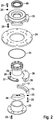
erfindungsgemäßes Wälzlager 10 in einer Explosionsdarstellung gemäß einer ersten beispielhaften Ausführungsform der vorliegenden Erfindung, - Fig. 2
- eine weitere beispielhafte Ausführung des
erfindungsgemäßen Wälzlagers 10 in einer Explosionsdarstellung, - Fig. 3
- eine Draufsicht sowie ein Schnittbild gemäß der Schnittlinie A-A eines Teils einer beispielhaften Rundläufervorrichtung und
- Fig. 4
- den in der
Figur 3 gezeigten Teil der Rundläufervorrichtung in perspektivischer Darstellung.
- Fig. 1
- an inventive rolling bearing 10 in an exploded view according to a first exemplary embodiment of the present invention,
- Fig. 2
- a further exemplary embodiment of the rolling
bearing 10 according to the invention in an exploded view, - Fig. 3
- a plan view and a sectional view along the section line AA of a part of an exemplary rotary apparatus and
- Fig. 4
- in the
FIG. 3 shown part of the rotary device in perspective view.
In der
Wie in der
Der erste Lagerkörper 11 umfasst ein erstes Ringelement 23 sowie der zweite Lagerkörper 12 ein zweites Ringelement 24. An den Ringelementen 23, 24 sind jeweils die ersten und zweiten Lagerringsegmente 19, 20, also die ersten Lagerringsegmente 19 am ersten Ringelement 23 und die zweiten Lagerringsegment 20 am zweiten Ringelement 24 vollständig umlaufend angeordnet. Ferner sind die Lagerringsegmente 19, 20 an den jeweiligen Ringelementen 23, 24 mittels Verbindungsmitteln 25 lösbar angeordnet. Als Verbindungsmittel 25 kommen bevorzugt Gewindeschrauben zum Einsatz. Dazu weisen Lagerringsegmente 19, 20 auf ihrer den Laufflächen 15, 16 abgewandten Seiten entsprechende Gewindebohrungen zur Aufnahme der Verbindungsmittel 25 auf. Die Ringelemente 23, 24 weise ebenfalls dazu korrespondierend positionierte Bohrungen auf, durch die die Gewindeschrauben geführt und die Ringelemente 23, 24 mit den Lagerringsegmenten 19, 20 verbunden werden. Alternativ ist die Verbindung zwischen den Lagerringsegmenten 19, 20 und den Ringelementen 23, 24 als form- und/oder kraftschlüssige Verbindung ausgebildet, beispielsweise als Klemm- und/oder Schnappverbindung.The
Die ersten und/oder die zweiten Ringelemente 23, 24 sind scheibenförmig ausgebildet, beispielsweise als Metall- oder Kunststoffscheibenelement. Besonders bevorzugt umfasst der erste Lagerkörper 11 ein Innenringelement 26. Das Innenringelement 26 ist derart ausgebildet, dass die inneren Mantelflächen 27 der ersten Lagerringsegmente 19 an der äußeren Mantelfläche 28 des Innenringelements 26 anliegen. Anders ausgedrückt entspricht der Außendurchmesser des Innenringelements 26 dem Innendurchmesser der aneinander zu einem Vollkreis zusammengefügten Lagerringsegmente 19.The first and / or the
Der erste Lagerkörper 11 umfasst eine hydraulische Kupplung 29 mittels derer der erste Lagerkörper 11 mit - in der
Besonders bevorzugt ist das Innenringelement 26 an dem ersten Ringelement 23 angeordnet. Anders ausgedrückt bildet das Innenringelement 26 eine zylindrische Verlängerung in axialer Richtung des ersten Ringelements 23. Weiter bevorzugt ist das Innenringelement 26 stoffschlüssig mit dem ersten Ringelement 23 verbunden. Vorteilhafter Weise umfasst der erste Lagerkörper 11 ein weiteres Innenringelement 30. Das weitere Innenringelement 30 ist dabei lösbar an dem ersten Innenringelement 26 angeordnet, beispielsweise durch Verschrauben. Der Außendurchmesser des weiteren Innenringelements 30 ist kleiner als der Innendurchmesser des zweiten Ringelements 24, so dass sich zwischen dem weiteren Innenringelement 30 und dem zweiten Ringelement 24 ein Spalt ergibt, der beispielsweise mit einem Dichtring 31 versehen ist.Particularly preferably, the
Bevorzugt ist an dem weiteren Innenringelement 30 ein Montageringelement 32 mit einer axialen Ausnehmung 33 zur Aufnahme der hydraulischen Kupplung 29 angeordnet. Das Montageringelement 32 und die hydraulische Kuppelung 29 sind vorzugsweise kraftschlüssig miteinander verbunden. Das Montageringelement 32 ist mittels mindestens zwei Querstegen 34, besonders bevorzugt mittels drei oder mehr Querstegen 34 mit dem weiteren Innenringelement 30 verbunden. Über das Montageringelement 32, die Querstege 34 und das weitere Innenringelement 30 ist der gesamte erste Lagerkörper 11 an der Achse 41 befestigt.Preferably, a mounting
Der erste Lagerkörper 11 ist relativ zu dem zweiten Lagerkörper 12 in axialer Richtung verstellbar ausgebildet. Hierzu sind beispielsweise - in der Zeichnung nicht gezeigte - axial verlaufende Gewindestangen an dem weiteren Innenringelement 30 angeordnet, die durch Bohrungen des Innenringelements 26 und/oder des ersten Ringelements 23 geführt sind. Auf den freien Enden der Gewindestangen sind Muttern angeordnet, mittels derer das erste Ringelement 23 mit den ersten Lagerringsegmenten 19 abgesenkt, d.h. von dem zweiten Lagerkörper 12 entfernt, und ggf. wieder angehoben, also zu dem zweiten Lagerkörper 12 hinbewegt werden können. Anstelle der Gewindestangen kommen alternativ Gewindeschrauben 35 zum Einsatz, die die Bohrungen des ersten Ringelements 23 und/oder des Innenringelements 26 geführt werden und in entsprechende Gewindebohrungen in dem weiteren Innenringelement 30 münden. Die Gewindeschrauben 35 sind vorzugsweise so lang ausgeführt, dass das erste Ringelement 23 mit den ersten Lagerringsegmenten 19 mittels der Gewindeschrauben 35 weit genug abgesenkt werden kann, um freien Zugang zu den Lagerringsegmenten 19 und den Wälzkörpern 17 zu erhalten.The
Optional sind an dem zweiten Ringelement 24 weitere Teile 44 angeordnet, so dass das Ringelement 24 als Trägerplatte für diese dient.Optionally,
Die
Besonders bevorzugt umfasst der erste Lagerring 13 ferner einen ersten äußeren Lagerring 45 und einen separaten ersten inneren Lagerring 46. Der erste äußere Lagerring 45 und der separate erste innere Lagerring 46 sind jeweils aus mehreren Lagerringsegmenten zusammengesetzt. Vorteilhafter Weise sind der erste innere Lagerring 46 und der zweite innere Lagerring 37 derart ausgebildet, dass die von diesen gebildete Lauffläche die Wälzkörper 17 zu mehr als 180° umschließt. So wird beim Öffnen des Wälzlagers 10 ein unerwünschtes Herausfallen der Wälzkörper 17 zuverlässig vermieden. Anders ausgedrückt können der erste äußere Lagerring 45 sowie der zweite äußere Lagerring 36 demontiert werden, während die Wälzkörper 17 durch den ersten inneren Lagerring 46 und den zweiten inneren Lagerring 37 gehalten an der Lauffläche verbleiben. Um die Wälzkörper 17 aus ihrer Umschließung freizugeben, sind die - beispielsweise miteinander verschraubten - ersten und zweiten inneren Lagerringe 46, 37 voneinander zu lösen und zumindest soweit auseinander zu bewegen, dass die Wälzkörper 17 freikommen.Particularly preferably, the first bearing ring 13 further comprises a first
Das in der
Vorzugsweise sind die in den
In der
Die Schmierung der in den
Claims (10)
- Rolling bearing (10), comprisinga first and a second bearing body (11, 12) which are arranged to be rotatable relative to one another about an axis (41),wherein the bearing bodies (11, 12) comprise first and second bearing rings (13, 14) having running surfaces (15, 16) which face one another and are designed and adapted to receive a plurality of rolling bodies (17),wherein the rolling bodies (17) are arranged between the running surfaces (15, 16) of the bearing rings (13, 14), whereinthe bearing rings (13, 14) are designed in multipart form by means of bearing ring segments (19, 20) which are detachable from one another,the first bearing body (11) is adapted and designed to be displaceable in the axial direction relative to the second bearing body (12),
characterized in that
the bearing bodies (11, 12) each comprise a first ring element (23) and a second ring element (24), wherein the first bearing ring segments (19) are detachably arranged on the first ring element (23) and the second bearing ring segments (20) are detachably arranged on the second ring element (24) over the entire periphery by means of connection means (25), and
the first ring element (23) and/or the second ring element (24) are/is at least substantially disc-shaped and
the first bearing body (11) is connected to a hydraulic coupling (29) for fastening the first bearing body (11) to the axis (41). - Rolling bearing (10) according to claim 1, characterised in that the interior ring element (26) is arranged on the first ring element (23).
- Rolling bearing (10) according to one of claims 1 or 2, characterised in that the first bearing body (11) comprises an interior ring element (26), wherein the inner peripheral surfaces (27) of the first bearing ring segments (19) abut the outer peripheral surface (28) of the interior ring element (26) in a positive locking manner.
- Rolling bearing (10) according to any one of claims 1 to 3, characterised in that the first bearing body (11) comprises a further interior ring element (30), wherein the further interior ring element (30) is detachably arranged on the interior ring element (26).
- Rolling bearing (10) according to claim 4, characterised in that a mounting ring element (32) having an axial recess (33) for receiving the hydraulic coupling (29) is arranged on the further interior ring element (30), wherein the mounting ring element (32) is connected to the further interior ring element (30) by means of at least two transverse webs (34).
- Rolling bearing (10) according to any one of claims 1 to 5, characterised in that the first bearing ring (13) comprises a first outer bearing ring (45) and a separate first inner bearing ring (46).
- Rolling bearing (10) according to any one of claims 1 to 6, characterised in that the second bearing ring (14) comprises a second outer bearing ring (36) and a separate second inner bearing ring (37).
- Rolling bearing (10) according to any one of claims 1 to 7, characterised in that the rolling bodies (17) and/or the bearing rings (12, 13, 36, 37, 45, 46) are made of plastics material.
- Rolling bearing (10) according to any one of claims 1 to 8, characterised in that the rolling bodies (17) are balls.
- Rotary device, comprising a fixed axis (41) and a carousel which is arranged to be rotatable about the fixed axis (41) and is to receive items for processing in the fish and meat processing industry, characterised in that the carousel is rotatably arranged on the fixed axis (41) by means of at least one rolling bearing (10) according to any one of claims 1 to 9.
Priority Applications (1)
| Application Number | Priority Date | Filing Date | Title |
|---|---|---|---|
| PL13763050T PL2898232T3 (en) | 2012-09-19 | 2013-09-16 | Rolling bearing, and rotary device with rolling bearing |
Applications Claiming Priority (2)
| Application Number | Priority Date | Filing Date | Title |
|---|---|---|---|
| DE102012108819.5A DE102012108819A1 (en) | 2012-09-19 | 2012-09-19 | Rolling and rotary device with roller bearings |
| PCT/EP2013/069147 WO2014044634A1 (en) | 2012-09-19 | 2013-09-16 | Rolling bearing, and rotary device with rolling bearing |
Publications (2)
| Publication Number | Publication Date |
|---|---|
| EP2898232A1 EP2898232A1 (en) | 2015-07-29 |
| EP2898232B1 true EP2898232B1 (en) | 2019-06-05 |
Family
ID=49209357
Family Applications (1)
| Application Number | Title | Priority Date | Filing Date |
|---|---|---|---|
| EP13763050.5A Active EP2898232B1 (en) | 2012-09-19 | 2013-09-16 | Rolling bearing, and rotary device with rolling bearing |
Country Status (16)
| Country | Link |
|---|---|
| US (1) | US9587677B2 (en) |
| EP (1) | EP2898232B1 (en) |
| JP (1) | JP6067122B2 (en) |
| KR (1) | KR101727001B1 (en) |
| CN (1) | CN104641135B (en) |
| BR (1) | BR112015005854B1 (en) |
| CA (1) | CA2884141C (en) |
| DE (1) | DE102012108819A1 (en) |
| DK (1) | DK2898232T3 (en) |
| ES (1) | ES2738824T3 (en) |
| IL (1) | IL237709A0 (en) |
| IN (1) | IN2015DN02365A (en) |
| MY (1) | MY175058A (en) |
| PL (1) | PL2898232T3 (en) |
| RU (1) | RU2600973C1 (en) |
| WO (1) | WO2014044634A1 (en) |
Families Citing this family (4)
| Publication number | Priority date | Publication date | Assignee | Title |
|---|---|---|---|---|
| CN108980200B (en) * | 2018-09-21 | 2020-05-05 | 浙江机电职业技术学院 | Split type plane bearing and assembling method thereof |
| CN109099056B (en) * | 2018-09-21 | 2020-05-05 | 浙江机电职业技术学院 | Bidirectional split type plane bearing and assembling method thereof |
| US11447927B2 (en) * | 2019-09-03 | 2022-09-20 | Caterpillar Inc. | Support assembly for a grading machine |
| CN112983973B (en) * | 2021-02-22 | 2023-06-16 | 蚌埠市昊德汽车轴承有限责任公司 | Replaceable pre-tightening spring tapered roller bearing |
Citations (1)
| Publication number | Priority date | Publication date | Assignee | Title |
|---|---|---|---|---|
| EP1426639A1 (en) * | 2002-12-05 | 2004-06-09 | Ab Skf | Method for mounting a two row tapered roller bearing with segmented bearing rings in a wind motor |
Family Cites Families (29)
| Publication number | Priority date | Publication date | Assignee | Title |
|---|---|---|---|---|
| DE1073248B (en) * | 1960-01-14 | Robert Zeuzem Frankfurt/M Fritz | Radially split rollers or ball bearings for built-in offset shafts | |
| US1071295A (en) * | 1913-08-26 | Paul Bruehl | Ball-bearing. | |
| GB191124655A (en) * | 1911-11-06 | 1912-06-13 | Walther Schutt | Improvements in and relating to Ball Bearings. |
| US1644611A (en) * | 1925-02-28 | 1927-10-04 | H Dux Company Inc Dr | Ball bearing |
| US1908474A (en) * | 1930-06-12 | 1933-05-09 | Hessbright Mfg Company | Connected bearing |
| DE903154C (en) * | 1951-11-15 | 1954-02-01 | Ladislav Karpisek | Dismountable roller bearing |
| DE959076C (en) * | 1953-12-11 | 1957-02-28 | Eisen & Stahlind Ag | Process for the production of remunerated segments of circular ball tracks or roller tracks, in particular for slewing gears of excavators, cranes or the like. |
| US3888357A (en) * | 1972-11-15 | 1975-06-10 | Caterpillar Tractor Co | Swing bearing with bolt-on segmented gear |
| DE3112303C2 (en) | 1981-03-28 | 1987-10-01 | FAG Kugelfischer Georg Schäfer KGaA, 8720 Schweinfurt | Cage divided in the circumferential direction for a double row spherical roller bearing |
| JPS5853919U (en) * | 1981-10-09 | 1983-04-12 | 日亜精密工業株式会社 | plastic bearings |
| JPS60208625A (en) * | 1984-03-30 | 1985-10-21 | Houriyou Sangyo Kk | Split bearing |
| JPS6124819A (en) * | 1984-07-13 | 1986-02-03 | Chubu Bearing Seisakusho:Kk | Bearing made of synthetic resin |
| US4622860A (en) * | 1985-06-24 | 1986-11-18 | Dresser Industries, Inc. | Method and apparatus for swing gear and bearing assembly for power mining shovel |
| JPS6213813A (en) * | 1985-07-11 | 1987-01-22 | Mitsubishi Electric Corp | Roller bearing device |
| JPH06208625A (en) * | 1993-01-11 | 1994-07-26 | Canon Inc | Method and device for processing image |
| RU2085772C1 (en) | 1994-12-23 | 1997-07-27 | Петр Петрович Гиляров | Antifriction bearing |
| US5599110A (en) * | 1995-06-07 | 1997-02-04 | Airlock, Incorporated | Bearing for a pressurized protective suit |
| CN2382886Y (en) | 1999-08-13 | 2000-06-14 | 刘生万 | Partial rolling bearing |
| DE202004007831U1 (en) * | 2004-05-14 | 2004-07-22 | Ab Skf | Multi-row roller bearing for wind power plant has first and second bearing rings, at least one with 3 segments, attachment flange for attaching second bearing ring to second machine part |
| JP4438511B2 (en) * | 2004-05-26 | 2010-03-24 | 株式会社ジェイテクト | Split outer ring, split roller bearing using it |
| DE102004058905B4 (en) | 2004-12-07 | 2010-02-18 | Aktiebolaget Skf | Rolling bearings with segmented bearing rings |
| CN200985951Y (en) | 2006-12-05 | 2007-12-05 | 瓦房店东旭非标准轴承集团有限公司 | Split-type impulse force conical roller bearing |
| DE102007062145A1 (en) | 2007-12-21 | 2009-06-25 | Schaeffler Kg | bearing arrangement |
| DE102008024055A1 (en) * | 2008-05-16 | 2009-11-19 | Schaeffler Kg | Bearing element, particularly bearing ring for roller bearing, sliding bearing or linear guide for use in power engineering including ocean current and transportation of raw materials, comprises support element and functional element |
| CN101852246B (en) * | 2010-05-12 | 2011-08-17 | 湖北工业大学 | Circulating roller split bearing |
| DE102010048479B4 (en) * | 2010-10-14 | 2014-07-10 | Schaeffler Technologies Gmbh & Co. Kg | The axial bearing |
| CN201884473U (en) * | 2010-12-22 | 2011-06-29 | 王金领 | Split type rolling bearing for connecting rod neck of crank shaft |
| JP5701145B2 (en) * | 2011-05-13 | 2015-04-15 | 株式会社椿本チエイン | Annular race ring module and axial roller bearing |
| DE102012206667B4 (en) * | 2012-04-23 | 2015-04-02 | Schaeffler Technologies Gmbh & Co. Kg | Axial radial bearings |
-
2012
- 2012-09-19 DE DE102012108819.5A patent/DE102012108819A1/en not_active Ceased
-
2013
- 2013-09-16 US US14/427,606 patent/US9587677B2/en active Active
- 2013-09-16 PL PL13763050T patent/PL2898232T3/en unknown
- 2013-09-16 WO PCT/EP2013/069147 patent/WO2014044634A1/en active Application Filing
- 2013-09-16 DK DK13763050.5T patent/DK2898232T3/en active
- 2013-09-16 CA CA2884141A patent/CA2884141C/en active Active
- 2013-09-16 ES ES13763050T patent/ES2738824T3/en active Active
- 2013-09-16 MY MYPI2015000678A patent/MY175058A/en unknown
- 2013-09-16 KR KR1020157006809A patent/KR101727001B1/en active IP Right Grant
- 2013-09-16 CN CN201380048926.1A patent/CN104641135B/en active Active
- 2013-09-16 JP JP2015532379A patent/JP6067122B2/en active Active
- 2013-09-16 BR BR112015005854-0A patent/BR112015005854B1/en active IP Right Grant
- 2013-09-16 EP EP13763050.5A patent/EP2898232B1/en active Active
- 2013-09-16 RU RU2015109370/11A patent/RU2600973C1/en active
-
2015
- 2015-03-12 IL IL237709A patent/IL237709A0/en unknown
- 2015-03-23 IN IN2365DEN2015 patent/IN2015DN02365A/en unknown
Patent Citations (1)
| Publication number | Priority date | Publication date | Assignee | Title |
|---|---|---|---|---|
| EP1426639A1 (en) * | 2002-12-05 | 2004-06-09 | Ab Skf | Method for mounting a two row tapered roller bearing with segmented bearing rings in a wind motor |
Also Published As
| Publication number | Publication date |
|---|---|
| DE102012108819A1 (en) | 2014-03-20 |
| BR112015005854B1 (en) | 2021-09-08 |
| CA2884141C (en) | 2017-08-01 |
| BR112015005854A2 (en) | 2017-07-04 |
| KR101727001B1 (en) | 2017-04-14 |
| US20150247531A1 (en) | 2015-09-03 |
| KR20150046156A (en) | 2015-04-29 |
| WO2014044634A1 (en) | 2014-03-27 |
| CN104641135B (en) | 2017-06-13 |
| RU2600973C1 (en) | 2016-10-27 |
| CA2884141A1 (en) | 2014-03-27 |
| IN2015DN02365A (en) | 2015-09-04 |
| EP2898232A1 (en) | 2015-07-29 |
| JP2015529316A (en) | 2015-10-05 |
| DK2898232T3 (en) | 2019-08-26 |
| US9587677B2 (en) | 2017-03-07 |
| ES2738824T3 (en) | 2020-01-27 |
| JP6067122B2 (en) | 2017-01-25 |
| IL237709A0 (en) | 2015-05-31 |
| PL2898232T3 (en) | 2019-11-29 |
| MY175058A (en) | 2020-06-04 |
| CN104641135A (en) | 2015-05-20 |
Similar Documents
| Publication | Publication Date | Title |
|---|---|---|
| DE3805350C2 (en) | ||
| EP2874805B1 (en) | Press roller | |
| EP2233760A1 (en) | Grease lubricated two-row roller bearing and storage system with such a roller bearing and a lubricating device | |
| EP2898232B1 (en) | Rolling bearing, and rotary device with rolling bearing | |
| EP1668263B1 (en) | Pivot bearing arrangement of a rotational body | |
| DE102010036093A1 (en) | Bearing element of a rudder stock bearing | |
| DE2032542A1 (en) | Expandable mandrel | |
| DE3736435C2 (en) | Mixer shaft seal and bearing for mixing tanks of concrete mixers | |
| DE2227412A1 (en) | ARRANGEMENT FOR STORING A RING ON THE COAT OF A ROTATING TUBE | |
| DE102008000204A1 (en) | Plate-cylinder bearing for rotary printing machine, has outer bearing race, and gap allowing elastic expansion of bearing race radially outward from inner side to enable expansion of outer and inner bearing races in radial direction | |
| DE4225810C2 (en) | Folding cylinder | |
| DE2515200C2 (en) | Sealing device for the bearings of the support shafts of overhung and exchangeable rolling disks | |
| DE10033894A1 (en) | Disassembly device for a self-adjusting bearing | |
| DE2921977A1 (en) | SHAFT DRIVE ELEMENT | |
| DE102007029548B3 (en) | Tool assembly for shaping tubular workpiece outer surfaces, without material removal, allows shaping rollers to be used on the axis bolt by changing the spacer rings without altering the dimensions to reduce wear | |
| EP3405302A1 (en) | Strand guiding roller for guiding a metal strand in a continuous casting facility | |
| EP0358790A1 (en) | Milling system | |
| WO2009059590A2 (en) | Plain bearing comprising a replaceable slideway lining | |
| DE10144974B4 (en) | Roll stand for rolling rod or tubular material | |
| EP3091647B1 (en) | Drive unit for an agitator and an agitator | |
| DE19509768C2 (en) | camp | |
| EP0721828A2 (en) | Cement-mixer truck | |
| DE102008027494A1 (en) | Multi-part roller | |
| DE19903339A1 (en) | Sliding bearing for sliding/rotating shafts has a bearing shell of two half-shells with a sliding insert which can be separated for a simple and rapid insert and/or shell replacement | |
| AT246548B (en) | Disk mill |
Legal Events
| Date | Code | Title | Description |
|---|---|---|---|
| PUAI | Public reference made under article 153(3) epc to a published international application that has entered the european phase |
Free format text: ORIGINAL CODE: 0009012 |
|
| 17P | Request for examination filed |
Effective date: 20150416 |
|
| AK | Designated contracting states |
Kind code of ref document: A1 Designated state(s): AL AT BE BG CH CY CZ DE DK EE ES FI FR GB GR HR HU IE IS IT LI LT LU LV MC MK MT NL NO PL PT RO RS SE SI SK SM TR |
|
| AX | Request for extension of the european patent |
Extension state: BA ME |
|
| DAX | Request for extension of the european patent (deleted) | ||
| 17Q | First examination report despatched |
Effective date: 20160718 |
|
| STAA | Information on the status of an ep patent application or granted ep patent |
Free format text: STATUS: EXAMINATION IS IN PROGRESS |
|
| GRAP | Despatch of communication of intention to grant a patent |
Free format text: ORIGINAL CODE: EPIDOSNIGR1 |
|
| STAA | Information on the status of an ep patent application or granted ep patent |
Free format text: STATUS: GRANT OF PATENT IS INTENDED |
|
| INTG | Intention to grant announced |
Effective date: 20181129 |
|
| GRAS | Grant fee paid |
Free format text: ORIGINAL CODE: EPIDOSNIGR3 |
|
| GRAJ | Information related to disapproval of communication of intention to grant by the applicant or resumption of examination proceedings by the epo deleted |
Free format text: ORIGINAL CODE: EPIDOSDIGR1 |
|
| GRAL | Information related to payment of fee for publishing/printing deleted |
Free format text: ORIGINAL CODE: EPIDOSDIGR3 |
|
| STAA | Information on the status of an ep patent application or granted ep patent |
Free format text: STATUS: EXAMINATION IS IN PROGRESS |
|
| GRAR | Information related to intention to grant a patent recorded |
Free format text: ORIGINAL CODE: EPIDOSNIGR71 |
|
| STAA | Information on the status of an ep patent application or granted ep patent |
Free format text: STATUS: GRANT OF PATENT IS INTENDED |
|
| GRAA | (expected) grant |
Free format text: ORIGINAL CODE: 0009210 |
|
| STAA | Information on the status of an ep patent application or granted ep patent |
Free format text: STATUS: THE PATENT HAS BEEN GRANTED |
|
| INTC | Intention to grant announced (deleted) | ||
| INTG | Intention to grant announced |
Effective date: 20190424 |
|
| AK | Designated contracting states |
Kind code of ref document: B1 Designated state(s): AL AT BE BG CH CY CZ DE DK EE ES FI FR GB GR HR HU IE IS IT LI LT LU LV MC MK MT NL NO PL PT RO RS SE SI SK SM TR |
|
| REG | Reference to a national code |
Ref country code: GB Ref legal event code: FG4D Free format text: NOT ENGLISH |
|
| REG | Reference to a national code |
Ref country code: CH Ref legal event code: EP |
|
| REG | Reference to a national code |
Ref country code: AT Ref legal event code: REF Ref document number: 1140290 Country of ref document: AT Kind code of ref document: T Effective date: 20190615 |
|
| REG | Reference to a national code |
Ref country code: IE Ref legal event code: FG4D Free format text: LANGUAGE OF EP DOCUMENT: GERMAN |
|
| REG | Reference to a national code |
Ref country code: DE Ref legal event code: R096 Ref document number: 502013012951 Country of ref document: DE |
|
| REG | Reference to a national code |
Ref country code: DK Ref legal event code: T3 Effective date: 20190822 |
|
| REG | Reference to a national code |
Ref country code: NL Ref legal event code: FP |
|
| REG | Reference to a national code |
Ref country code: LT Ref legal event code: MG4D |
|
| PG25 | Lapsed in a contracting state [announced via postgrant information from national office to epo] |
Ref country code: HR Free format text: LAPSE BECAUSE OF FAILURE TO SUBMIT A TRANSLATION OF THE DESCRIPTION OR TO PAY THE FEE WITHIN THE PRESCRIBED TIME-LIMIT Effective date: 20190605 Ref country code: NO Free format text: LAPSE BECAUSE OF FAILURE TO SUBMIT A TRANSLATION OF THE DESCRIPTION OR TO PAY THE FEE WITHIN THE PRESCRIBED TIME-LIMIT Effective date: 20190905 Ref country code: SE Free format text: LAPSE BECAUSE OF FAILURE TO SUBMIT A TRANSLATION OF THE DESCRIPTION OR TO PAY THE FEE WITHIN THE PRESCRIBED TIME-LIMIT Effective date: 20190605 Ref country code: FI Free format text: LAPSE BECAUSE OF FAILURE TO SUBMIT A TRANSLATION OF THE DESCRIPTION OR TO PAY THE FEE WITHIN THE PRESCRIBED TIME-LIMIT Effective date: 20190605 Ref country code: AL Free format text: LAPSE BECAUSE OF FAILURE TO SUBMIT A TRANSLATION OF THE DESCRIPTION OR TO PAY THE FEE WITHIN THE PRESCRIBED TIME-LIMIT Effective date: 20190605 Ref country code: LT Free format text: LAPSE BECAUSE OF FAILURE TO SUBMIT A TRANSLATION OF THE DESCRIPTION OR TO PAY THE FEE WITHIN THE PRESCRIBED TIME-LIMIT Effective date: 20190605 |
|
| PG25 | Lapsed in a contracting state [announced via postgrant information from national office to epo] |
Ref country code: BG Free format text: LAPSE BECAUSE OF FAILURE TO SUBMIT A TRANSLATION OF THE DESCRIPTION OR TO PAY THE FEE WITHIN THE PRESCRIBED TIME-LIMIT Effective date: 20190905 Ref country code: RS Free format text: LAPSE BECAUSE OF FAILURE TO SUBMIT A TRANSLATION OF THE DESCRIPTION OR TO PAY THE FEE WITHIN THE PRESCRIBED TIME-LIMIT Effective date: 20190605 Ref country code: GR Free format text: LAPSE BECAUSE OF FAILURE TO SUBMIT A TRANSLATION OF THE DESCRIPTION OR TO PAY THE FEE WITHIN THE PRESCRIBED TIME-LIMIT Effective date: 20190906 Ref country code: LV Free format text: LAPSE BECAUSE OF FAILURE TO SUBMIT A TRANSLATION OF THE DESCRIPTION OR TO PAY THE FEE WITHIN THE PRESCRIBED TIME-LIMIT Effective date: 20190605 |
|
| REG | Reference to a national code |
Ref country code: ES Ref legal event code: FG2A Ref document number: 2738824 Country of ref document: ES Kind code of ref document: T3 Effective date: 20200127 |
|
| PG25 | Lapsed in a contracting state [announced via postgrant information from national office to epo] |
Ref country code: SK Free format text: LAPSE BECAUSE OF FAILURE TO SUBMIT A TRANSLATION OF THE DESCRIPTION OR TO PAY THE FEE WITHIN THE PRESCRIBED TIME-LIMIT Effective date: 20190605 Ref country code: RO Free format text: LAPSE BECAUSE OF FAILURE TO SUBMIT A TRANSLATION OF THE DESCRIPTION OR TO PAY THE FEE WITHIN THE PRESCRIBED TIME-LIMIT Effective date: 20190605 Ref country code: CZ Free format text: LAPSE BECAUSE OF FAILURE TO SUBMIT A TRANSLATION OF THE DESCRIPTION OR TO PAY THE FEE WITHIN THE PRESCRIBED TIME-LIMIT Effective date: 20190605 Ref country code: EE Free format text: LAPSE BECAUSE OF FAILURE TO SUBMIT A TRANSLATION OF THE DESCRIPTION OR TO PAY THE FEE WITHIN THE PRESCRIBED TIME-LIMIT Effective date: 20190605 Ref country code: PT Free format text: LAPSE BECAUSE OF FAILURE TO SUBMIT A TRANSLATION OF THE DESCRIPTION OR TO PAY THE FEE WITHIN THE PRESCRIBED TIME-LIMIT Effective date: 20191007 |
|
| PG25 | Lapsed in a contracting state [announced via postgrant information from national office to epo] |
Ref country code: SM Free format text: LAPSE BECAUSE OF FAILURE TO SUBMIT A TRANSLATION OF THE DESCRIPTION OR TO PAY THE FEE WITHIN THE PRESCRIBED TIME-LIMIT Effective date: 20190605 Ref country code: IT Free format text: LAPSE BECAUSE OF FAILURE TO SUBMIT A TRANSLATION OF THE DESCRIPTION OR TO PAY THE FEE WITHIN THE PRESCRIBED TIME-LIMIT Effective date: 20190605 |
|
| REG | Reference to a national code |
Ref country code: DE Ref legal event code: R097 Ref document number: 502013012951 Country of ref document: DE |
|
| PG25 | Lapsed in a contracting state [announced via postgrant information from national office to epo] |
Ref country code: TR Free format text: LAPSE BECAUSE OF FAILURE TO SUBMIT A TRANSLATION OF THE DESCRIPTION OR TO PAY THE FEE WITHIN THE PRESCRIBED TIME-LIMIT Effective date: 20190605 |
|
| PLBE | No opposition filed within time limit |
Free format text: ORIGINAL CODE: 0009261 |
|
| STAA | Information on the status of an ep patent application or granted ep patent |
Free format text: STATUS: NO OPPOSITION FILED WITHIN TIME LIMIT |
|
| 26N | No opposition filed |
Effective date: 20200306 |
|
| PG25 | Lapsed in a contracting state [announced via postgrant information from national office to epo] |
Ref country code: SI Free format text: LAPSE BECAUSE OF FAILURE TO SUBMIT A TRANSLATION OF THE DESCRIPTION OR TO PAY THE FEE WITHIN THE PRESCRIBED TIME-LIMIT Effective date: 20190605 Ref country code: MC Free format text: LAPSE BECAUSE OF FAILURE TO SUBMIT A TRANSLATION OF THE DESCRIPTION OR TO PAY THE FEE WITHIN THE PRESCRIBED TIME-LIMIT Effective date: 20190605 |
|
| REG | Reference to a national code |
Ref country code: CH Ref legal event code: PL |
|
| PG25 | Lapsed in a contracting state [announced via postgrant information from national office to epo] |
Ref country code: CH Free format text: LAPSE BECAUSE OF NON-PAYMENT OF DUE FEES Effective date: 20190930 Ref country code: IE Free format text: LAPSE BECAUSE OF NON-PAYMENT OF DUE FEES Effective date: 20190916 Ref country code: LI Free format text: LAPSE BECAUSE OF NON-PAYMENT OF DUE FEES Effective date: 20190930 Ref country code: LU Free format text: LAPSE BECAUSE OF NON-PAYMENT OF DUE FEES Effective date: 20190916 |
|
| REG | Reference to a national code |
Ref country code: BE Ref legal event code: MM Effective date: 20190930 |
|
| PG25 | Lapsed in a contracting state [announced via postgrant information from national office to epo] |
Ref country code: BE Free format text: LAPSE BECAUSE OF NON-PAYMENT OF DUE FEES Effective date: 20190930 |
|
| PG25 | Lapsed in a contracting state [announced via postgrant information from national office to epo] |
Ref country code: FR Free format text: LAPSE BECAUSE OF NON-PAYMENT OF DUE FEES Effective date: 20190930 |
|
| REG | Reference to a national code |
Ref country code: AT Ref legal event code: MM01 Ref document number: 1140290 Country of ref document: AT Kind code of ref document: T Effective date: 20190916 |
|
| PG25 | Lapsed in a contracting state [announced via postgrant information from national office to epo] |
Ref country code: AT Free format text: LAPSE BECAUSE OF NON-PAYMENT OF DUE FEES Effective date: 20190916 |
|
| PG25 | Lapsed in a contracting state [announced via postgrant information from national office to epo] |
Ref country code: CY Free format text: LAPSE BECAUSE OF FAILURE TO SUBMIT A TRANSLATION OF THE DESCRIPTION OR TO PAY THE FEE WITHIN THE PRESCRIBED TIME-LIMIT Effective date: 20190605 |
|
| PG25 | Lapsed in a contracting state [announced via postgrant information from national office to epo] |
Ref country code: MT Free format text: LAPSE BECAUSE OF FAILURE TO SUBMIT A TRANSLATION OF THE DESCRIPTION OR TO PAY THE FEE WITHIN THE PRESCRIBED TIME-LIMIT Effective date: 20190605 Ref country code: HU Free format text: LAPSE BECAUSE OF FAILURE TO SUBMIT A TRANSLATION OF THE DESCRIPTION OR TO PAY THE FEE WITHIN THE PRESCRIBED TIME-LIMIT; INVALID AB INITIO Effective date: 20130916 |
|
| PG25 | Lapsed in a contracting state [announced via postgrant information from national office to epo] |
Ref country code: MK Free format text: LAPSE BECAUSE OF FAILURE TO SUBMIT A TRANSLATION OF THE DESCRIPTION OR TO PAY THE FEE WITHIN THE PRESCRIBED TIME-LIMIT Effective date: 20190605 |
|
| P01 | Opt-out of the competence of the unified patent court (upc) registered |
Effective date: 20230517 |
|
| PGFP | Annual fee paid to national office [announced via postgrant information from national office to epo] |
Ref country code: NL Payment date: 20230920 Year of fee payment: 11 Ref country code: GB Payment date: 20230921 Year of fee payment: 11 |
|
| PGFP | Annual fee paid to national office [announced via postgrant information from national office to epo] |
Ref country code: PL Payment date: 20230711 Year of fee payment: 11 Ref country code: IS Payment date: 20230718 Year of fee payment: 11 Ref country code: DK Payment date: 20230921 Year of fee payment: 11 Ref country code: DE Payment date: 20230919 Year of fee payment: 11 |
|
| PGFP | Annual fee paid to national office [announced via postgrant information from national office to epo] |
Ref country code: ES Payment date: 20231019 Year of fee payment: 11 |