EP2896519B1 - Structure de suspension pour dispositif d'entraînement de moteur-roue - Google Patents
Structure de suspension pour dispositif d'entraînement de moteur-roue Download PDFInfo
- Publication number
- EP2896519B1 EP2896519B1 EP13836890.7A EP13836890A EP2896519B1 EP 2896519 B1 EP2896519 B1 EP 2896519B1 EP 13836890 A EP13836890 A EP 13836890A EP 2896519 B1 EP2896519 B1 EP 2896519B1
- Authority
- EP
- European Patent Office
- Prior art keywords
- trailing arm
- wall portion
- rear end
- vehicle
- drive device
- Prior art date
- Legal status (The legal status is an assumption and is not a legal conclusion. Google has not performed a legal analysis and makes no representation as to the accuracy of the status listed.)
- Not-in-force
Links
- 239000000725 suspension Substances 0.000 title claims description 55
- 239000006096 absorbing agent Substances 0.000 claims description 13
- 230000035939 shock Effects 0.000 claims description 13
- 230000008878 coupling Effects 0.000 claims description 11
- 238000010168 coupling process Methods 0.000 claims description 11
- 238000005859 coupling reaction Methods 0.000 claims description 11
- 239000000463 material Substances 0.000 claims description 3
- 230000009467 reduction Effects 0.000 description 28
- 238000005452 bending Methods 0.000 description 8
- 230000003014 reinforcing effect Effects 0.000 description 8
- 230000002093 peripheral effect Effects 0.000 description 6
- 230000007246 mechanism Effects 0.000 description 5
- 230000004048 modification Effects 0.000 description 5
- 238000012986 modification Methods 0.000 description 5
- 239000002184 metal Substances 0.000 description 3
- 230000000694 effects Effects 0.000 description 2
- 210000002105 tongue Anatomy 0.000 description 2
- 239000003381 stabilizer Substances 0.000 description 1
- XLYOFNOQVPJJNP-UHFFFAOYSA-N water Substances O XLYOFNOQVPJJNP-UHFFFAOYSA-N 0.000 description 1
- 238000003466 welding Methods 0.000 description 1
Images

Classifications
-
- B—PERFORMING OPERATIONS; TRANSPORTING
- B62—LAND VEHICLES FOR TRAVELLING OTHERWISE THAN ON RAILS
- B62D—MOTOR VEHICLES; TRAILERS
- B62D21/00—Understructures, i.e. chassis frame on which a vehicle body may be mounted
- B62D21/11—Understructures, i.e. chassis frame on which a vehicle body may be mounted with resilient means for suspension, e.g. of wheels or engine; sub-frames for mounting engine or suspensions
-
- B—PERFORMING OPERATIONS; TRANSPORTING
- B60—VEHICLES IN GENERAL
- B60G—VEHICLE SUSPENSION ARRANGEMENTS
- B60G21/00—Interconnection systems for two or more resiliently-suspended wheels, e.g. for stabilising a vehicle body with respect to acceleration, deceleration or centrifugal forces
- B60G21/02—Interconnection systems for two or more resiliently-suspended wheels, e.g. for stabilising a vehicle body with respect to acceleration, deceleration or centrifugal forces permanently interconnected
- B60G21/04—Interconnection systems for two or more resiliently-suspended wheels, e.g. for stabilising a vehicle body with respect to acceleration, deceleration or centrifugal forces permanently interconnected mechanically
- B60G21/05—Interconnection systems for two or more resiliently-suspended wheels, e.g. for stabilising a vehicle body with respect to acceleration, deceleration or centrifugal forces permanently interconnected mechanically between wheels on the same axle but on different sides of the vehicle, i.e. the left and right wheel suspensions being interconnected
- B60G21/051—Trailing arm twist beam axles
-
- B—PERFORMING OPERATIONS; TRANSPORTING
- B60—VEHICLES IN GENERAL
- B60K—ARRANGEMENT OR MOUNTING OF PROPULSION UNITS OR OF TRANSMISSIONS IN VEHICLES; ARRANGEMENT OR MOUNTING OF PLURAL DIVERSE PRIME-MOVERS IN VEHICLES; AUXILIARY DRIVES FOR VEHICLES; INSTRUMENTATION OR DASHBOARDS FOR VEHICLES; ARRANGEMENTS IN CONNECTION WITH COOLING, AIR INTAKE, GAS EXHAUST OR FUEL SUPPLY OF PROPULSION UNITS IN VEHICLES
- B60K7/00—Disposition of motor in, or adjacent to, traction wheel
- B60K7/0007—Disposition of motor in, or adjacent to, traction wheel the motor being electric
-
- B—PERFORMING OPERATIONS; TRANSPORTING
- B60—VEHICLES IN GENERAL
- B60G—VEHICLE SUSPENSION ARRANGEMENTS
- B60G2200/00—Indexing codes relating to suspension types
- B60G2200/20—Semi-rigid axle suspensions
- B60G2200/21—Trailing arms connected by a torsional beam, i.e. twist-beam axles
-
- B—PERFORMING OPERATIONS; TRANSPORTING
- B60—VEHICLES IN GENERAL
- B60G—VEHICLE SUSPENSION ARRANGEMENTS
- B60G2200/00—Indexing codes relating to suspension types
- B60G2200/40—Indexing codes relating to the wheels in the suspensions
- B60G2200/422—Driving wheels or live axles
-
- B—PERFORMING OPERATIONS; TRANSPORTING
- B60—VEHICLES IN GENERAL
- B60G—VEHICLE SUSPENSION ARRANGEMENTS
- B60G2204/00—Indexing codes related to suspensions per se or to auxiliary parts
- B60G2204/10—Mounting of suspension elements
- B60G2204/18—Mounting of vehicle engines
- B60G2204/182—Electric motor on wheel support
-
- B—PERFORMING OPERATIONS; TRANSPORTING
- B60—VEHICLES IN GENERAL
- B60G—VEHICLE SUSPENSION ARRANGEMENTS
- B60G2300/00—Indexing codes relating to the type of vehicle
- B60G2300/50—Electric vehicles; Hybrid vehicles
-
- B—PERFORMING OPERATIONS; TRANSPORTING
- B60—VEHICLES IN GENERAL
- B60K—ARRANGEMENT OR MOUNTING OF PROPULSION UNITS OR OF TRANSMISSIONS IN VEHICLES; ARRANGEMENT OR MOUNTING OF PLURAL DIVERSE PRIME-MOVERS IN VEHICLES; AUXILIARY DRIVES FOR VEHICLES; INSTRUMENTATION OR DASHBOARDS FOR VEHICLES; ARRANGEMENTS IN CONNECTION WITH COOLING, AIR INTAKE, GAS EXHAUST OR FUEL SUPPLY OF PROPULSION UNITS IN VEHICLES
- B60K17/00—Arrangement or mounting of transmissions in vehicles
- B60K17/04—Arrangement or mounting of transmissions in vehicles characterised by arrangement, location or kind of gearing
- B60K17/043—Transmission unit disposed in on near the vehicle wheel, or between the differential gear unit and the wheel
-
- B—PERFORMING OPERATIONS; TRANSPORTING
- B60—VEHICLES IN GENERAL
- B60K—ARRANGEMENT OR MOUNTING OF PROPULSION UNITS OR OF TRANSMISSIONS IN VEHICLES; ARRANGEMENT OR MOUNTING OF PLURAL DIVERSE PRIME-MOVERS IN VEHICLES; AUXILIARY DRIVES FOR VEHICLES; INSTRUMENTATION OR DASHBOARDS FOR VEHICLES; ARRANGEMENTS IN CONNECTION WITH COOLING, AIR INTAKE, GAS EXHAUST OR FUEL SUPPLY OF PROPULSION UNITS IN VEHICLES
- B60K7/00—Disposition of motor in, or adjacent to, traction wheel
- B60K2007/0038—Disposition of motor in, or adjacent to, traction wheel the motor moving together with the wheel axle
-
- B—PERFORMING OPERATIONS; TRANSPORTING
- B60—VEHICLES IN GENERAL
- B60K—ARRANGEMENT OR MOUNTING OF PROPULSION UNITS OR OF TRANSMISSIONS IN VEHICLES; ARRANGEMENT OR MOUNTING OF PLURAL DIVERSE PRIME-MOVERS IN VEHICLES; AUXILIARY DRIVES FOR VEHICLES; INSTRUMENTATION OR DASHBOARDS FOR VEHICLES; ARRANGEMENTS IN CONNECTION WITH COOLING, AIR INTAKE, GAS EXHAUST OR FUEL SUPPLY OF PROPULSION UNITS IN VEHICLES
- B60K7/00—Disposition of motor in, or adjacent to, traction wheel
- B60K2007/0092—Disposition of motor in, or adjacent to, traction wheel the motor axle being coaxial to the wheel axle
Definitions
- the present invention relates to suspension devices that attach an in-wheel motor drive device to a vehicle body.
- Trailing arm suspension devices are widely used as suspension devices for vehicles. Torsion beam suspension devices in which right and left trailing arms are connected by a cross beam (also called “torsion beam”) are advantageous in terms of cost, and are used for rear wheels of small cars.
- a trailing arm suspension device described in Japanese Unexamined Patent Application Publication No. H08-127211 (Patent Literature 1) is known as an example of such trailing arm suspension devices.
- a spindle for attaching a wheel is provided at the rear end of each trailing arm. This spindle protrudes outward in the lateral direction of a vehicle.
- suspension devices described in Japanese Unexamined Patent Application Publication Nos. 2010-116017 (Patent Literature 2) and 2006-27310 (Patent Literature 3) are known as suspension devices that include trailing arms and suspend in-wheel motor drive devices.
- each in-wheel motor drive device is placed inward of the trailing arm in the lateral direction of a vehicle.
- each in-wheel motor drive device is placed outward of the trailing arm in the lateral direction of a vehicle.
- US 2009/038865 A1 discloses a suspension structure for an in-wheel motor, comprising the features mentioned in the preamble of claim 1.
- a suspension structure for an in-wheel drive device is a suspension structure for an in-wheel drive device, according to claim 1.
- the lower surface of the in-wheel motor drive device is covered by the rear end region of the trailing arm and the bracket, the lower surface of the in-wheel motor drive device can be protected. Bumps on a road, stones from the road, etc. can therefore be prevented from hitting the lower surface of the in-wheel motor drive device.
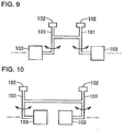
- the in-wheel motor drive device is heavier than a wheel, and an excessive bending moment is therefore applied to a trailing arm 101 as shown by arrow in Figs. 9 and 10 .
- the bending moment can be reduced.
- the in-wheel motor drive device is coupled and fixed to the trailing arm via the bracket, the shape of the trailing arm and the shape of the in-wheel motor drive device can be designed with more flexibility.
- the shape of the bracket is not particularly limited.
- the bracket of the present invention is formed by a plate material, and includes a projecting wall portion projecting outward in the lateral direction of the vehicle from the rear end region of the trailing arm and a vertical wall portion extending upward from the projecting wall portion. According to this embodiment, the protection of the lower surface of the in-wheel motor drive device can be implemented in a preferable manner.
- the projecting wall portion has a drain hole extending therethrough in a vertical direction. According to this embodiment, water, gravel, etc. can be prevented from gathering on the upper surface of the projecting wall portion.
- the rear end region of the trailing arm has, at a position in the longitudinal direction of the vehicle which is included in a range from a front end to a rear end of the bracket in the longitudinal direction of the vehicle, a coupling portion that is coupled to a lower end of a shock absorber extending from the vehicle body.
- the coupled portion between the shock absorber and the trailing arm can be located closer to the in-wheel motor drive device, which is advantageous in terms of layout of the suspension device.
- vertical swinging of the in-wheel motor drive device can be effectively damped.
- the trailing arm need only extend in the longitudinal direction of the vehicle, and the extending direction of the trailing arm is not particularly limited.
- the shape of the trailing arm in section is not particularly limited.
- the radial dimension of the in-wheel motor drive device is typically larger than the vertical dimension of the shape of the trailing arm in section.
- the rear end region of the trailing arm extends linearly so as to be substantially horizontal, and a central region of the trailing arm extends in a gently tilted manner with respect to the rear end region such that a front end of the central region is higher than a rear end thereof.
- the in-wheel motor drive device can be attached to the trailing arm in a preferable manner in a small space between the vehicle body and the ground.
- the central region of the trailing arm can cover a front surface of the in-wheel motor drive device, and the front surface of the in-wheel motor drive device can be protected from bumps on the road, stones from the road, etc.
- the in-wheel motor drive devices in a suspension structure in which in-wheel motor drive devices are attached to trailing arms, the in-wheel motor drive devices can be protected from bumps on the road, stones from the road, etc. Accordingly, reliability and durability of the in-wheel motor drive devices can be improved while retaining advantages of trailing arm suspensions in terms of cost.
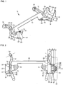
- Fig. 1 is a perspective view showing a suspension structure for an in-wheel motor drive device according to an embodiment of the present invention.
- Fig. 1 is a perspective view showing a suspension structure for an in-wheel motor drive device according to an embodiment of the present invention.
- Fig. 2 is a plan view showing the suspension structure of the embodiment.
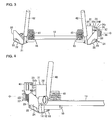
- Fig. 3 is a rear view showing the suspension structure of the embodiment as viewed from the rear of a vehicle.
- Fig. 4 is a front view showing a part of the suspension structure of the embodiment as viewed from the front of the vehicle.
- Fig. 5 is a side view showing the suspension structure of the embodiment as viewed from outside in the lateral direction of the vehicle.
- the suspension structure of the embodiment uses a torsion beam suspension member 11 that includes a pair of trailing arms 12 extending in the longitudinal direction of the vehicle and separated from each other in the lateral direction of the vehicle and a cross beam 13 disposed between the pair of trailing arms 12, 12 and extending in the lateral direction of the vehicle. Both ends of the cross beam 13 are connected to each of the trailing arm 12 respectively.
- the trailing arms 12 and the cross beam 13 are pipe members made of a metal. Both ends of the cross beam 13 are connected to central regions of the trailing arms 12.
- Each trailing arm 12 has at its front end a pivot 14 that is attached to a member of the vehicle body.
- the pivot center of the pivot 14 extends in a tilted manner with respect to the lateral direction of the vehicle such that the inner side of the pivot center in the lateral direction of the vehicle is located forward of the outer side of the pivot center in the lateral direction of the vehicle, as shown by dot-and-dash lines in Fig. 2 .
- the torsion beam suspension member 11 further includes spring lower seats 16 that receive the lower ends of coil springs 41, respectively.
- the spring lower seats 16 are respectively provided on plates 15 each provided rearward of the connection portion between the cross beam 13 and a corresponding one of the trailing arms 12 so as to adjoin this connection portion.
- Each plate 15 is formed by bending and forming a metal plate.
- Each plate 15 is connected to the central and rear end regions of a corresponding one of the trailing arms 12, and is connected to a corresponding one of the ends of the cross beam 13.
- Each coil spring 41 is a component of a suspension device, and serves as a spring that reduces swinging of a corresponding one of the trailing arms 12 about the pivot 14.
- the lower end of the coil spring 41 is supported by the spring lower seat 16 at a position inward of the rear end region of the trailing arm 12 in the lateral direction of the vehicle.
- the upper end of the coil spring 41 supports a vehicle body member, not shown.
- Each trailing arm 12 has at its rear end a coupling portion 18 that is coupled to the lower end of a corresponding one of shock absorbers 42.
- the trailing arm 12 is coupled to the lower end of the shock absorber 42 via this coupling portion 18.
- Each shock absorber 42 is a component of the suspension device, and serves as a damper that damps swinging of a corresponding one of the trailing arms 12 about the pivot 14.
- the upper end of the shock absorber 42 supports a vehicle body member, not shown.
- the rear end region 12b of the trailing arm 12 extends linearly so as to be substantially horizontal.
- the central region 12c of the trailing arm 12 extends in a gently tilted manner with respect to the rear end region 12b such that the front end of the central region 12c is higher than the rear end thereof.
- a front end region 12f of the trailing arm 12 is located higher than the rear end region 12b and extends linearly so as to be substantially horizontal.
- An in-wheel motor drive device 31 is coupled and fixed to the rear end region of each trailing arm 12.
- the in-wheel motor drive device 31 has a motor unit 32, a reduction gear unit 33, and a hub unit 34, and is coupled and fixed to a bracket 21 attached to the trailing arm 12 in such an attitude that a hub shaft 35 that is rotatably supported by the hub unit 34 extends in the lateral direction of the vehicle.
- the tip end of the hub shaft 35 extends so as to protrude from the hub unit 34, and has a plurality of bolts 37 in order to couple to a road wheel of a wheel 44.
- the motor unit 32, the reduction gear unit 33, and the hub unit 34 form a common rotation axis O.
- the motor unit 32, the reduction gear unit 33, and the hub unit 34 are arranged in this order as viewed in the direction of the rotation axis O.
- Each of the motor unit 32 and the reduction gear unit 33 includes a non-rotary casing.
- An outer peripheral member of the hub unit 34 corresponds to an outer ring of a bearing, and is connected to the casings of the motor unit 32 and the reduction gear unit 33.
- the hub shaft 35 that is rotatably supported by the outer peripheral member of the hub unit 34 is a rotary member extending along the rotation axis O.
- a terminal box 36 for power cables is formed on the front side of the casing of the motor unit 32.
- the motor unit 32 has a generally cylindrical shape about the rotation axis O, and contains a rotor and a stator in the casing.
- the reduction gear unit 33 has a generally cylindrical shape about the rotation axis O, and contains, e.g., a cycloidal reduction gear mechanism in the casing.
- the reduction gear unit 33 reduces the speed of rotation input from the motor unit 32 and outputs the reduced rotation to the hub unit 34.
- the cycloidal reduction gear mechanism is smaller and lighter than a planetary gear reduction gear mechanism, and can reduce the speed of rotation input to less than 1/10.
- the cycloidal reduction gear mechanism is advantageous as a reduction gear mechanism of the in-wheel motor drive device.
- the axial dimension A of the motor unit 32 is the dimension from the end face in the direction of the axis O of the motor unit 32 excluding protrusions such as screw heads to the boundary between the motor unit 32 and the reduction gear unit 33.
- the axial dimension B of the reduction gear unit 33 is the dimension from the boundary between the motor unit 32 and the reduction gear unit 33 to the boundary between the reduction gear unit 33 and the hub unit 34.
- the axial dimension C of the hub unit 34 is the dimension from the boundary between the reduction gear unit 33 and the hub unit 34 to the end face in the direction of the axis O of an outer ring portion of the hub unit 34 excluding the hub shaft 35.
- the axial dimension B is smaller than the axial dimension A
- the axial dimension C is smaller than the axial dimension B.
- the radial dimension of the reduction gear unit 33 is smaller than that of the motor unit 32.
- the radial dimension of the hub unit 34 is smaller than that of the reduction gear unit 33.
- An outward flange 34f is formed on the reduction gear unit 33 side of the outer peripheral surface of the hub unit 34 to fill the gap formed by the difference in radial dimension between the reduction gear unit 33 and the hub unit 34.
- the outward flange 34f has an end face 34s.
- the end face 34s is perpendicular to the rotation axis O.
- a plurality of triangular ribs 33r are formed on the outer periphery of the reduction gear unit 33 at predetermined intervals in the circumferential direction.
- the triangular ribs 33r are also connected to the motor unit 32 to reinforce the connection between the motor unit 32 and the reduction gear unit 33 which have different radial dimensions from each other. Moreover, bolt holes 33s are formed in the outer periphery of the upper part of the reduction gear unit 33 in order to couple and fix a brake caliper 45.
- the wheel 44 is a well-known wheel having a rubber tire attached to the outer periphery of the road wheel, and is fixed to the hub shaft 35 by the bolts 37.
- the reduction gear unit 33 and the hub unit 34 are thus completely accommodated in an inner space region of the wheel 44, as shown by the dimensions B and C in Fig. 2 .
- the outer portion in the direction of the axis O of the motor unit 32 is accommodated in the inner space region of the wheel 44, and the inner portion in the direction of the axis O of the motor unit 32 is located inward of the wheel 44 in the lateral direction of the vehicle.
- the bracket 21 is connected to the rear end region of the trailing arm 12 by welding etc., and protrudes upward from the rear end region of the trailing arm 12.
- the in-wheel motor drive device 31 is coupled to the rear end region of the trailing arm 12 via the bracket 21, and is located above the rear end region of the trailing arm 12.
- the bracket 21 is formed by a plate material made of a metal, and as shown in Figs. 3 and 4 , includes a projecting wall portion 22 projecting outward in the lateral direction of the vehicle from the rear end region of the trailing arm 12, a vertical wall portion 23 extending upward from the projecting wall portion 22, a front wall portion 24 bent at 90 degrees from the front edge of the vertical wall portion 23 so as to extend in the lateral direction of the vehicle and connected to the rear end region of the trailing arm 12, and a rear wall portion 25 bent at 90 degrees from the rear edge of the vertical wall portion 23 so as to extend in the lateral direction of the vehicle and connected to the rear end of the trailing arm 12.
- the vertical wall portion 23 is a wall extending vertical to the ground.
- the vertical wall portion 23 is perpendicular to the lateral direction of the vehicle.
- a substantially semicircular cutout portion 23c extending downward is formed in the upper edge of the vertical wall portion 23.
- the peripheral edge of the cutout portion 23c extends in an arc shape, and matches the end face 34s of the hub unit 34 of the in-wheel motor drive device 31, as shown in Fig. 5 .
- a plurality of through holes 23h are formed in the peripheral edge of the cutout portion 23c, and bolt holes are formed in the end face 34s at positions corresponding to the through holes 23h.
- a plurality of bolts 43 extending through the through holes 23h are tightened into the bolt holes of the end face 34s, whereby the in-wheel motor drive device 31 is coupled and fixed to the bracket 21.
- the projecting wall portion 22 is located between the front wall portion 24 and the rear wall portion 25 as viewed in the vertical direction.
- a drain hole 26 extending through the bracket 21 in the vertical direction is formed between the front wall portion 24 and the projecting wall portion 22.
- a drain hole 27 extending through the bracket 21 in the vertical direction is formed between the projecting wall portion 22 and the rear wall portion 25. Rainwater, gravel, etc. does not collect on the upper surface of the projecting wall portion 22 due to the drain holes 26, 27.
- the shock absorbers 42 are placed so that the in-wheel motor drive devices 31 are suspended advantageously in terms of layout.
- the coupling portion 18 for the shock absorber 42 is a protrusion protruding inward in the lateral direction of the vehicle from the rear end of the trailing arm 12, and is located forward of the rear wall portion 25 forming the rear end of the bracket 21 in the longitudinal direction of the vehicle.
- the position of the coupling portion 18 in the longitudinal direction of the vehicle is thus included in the range from the front wall portion 24 forming the front end of the bracket 21 to the rear wall portion 25 in the longitudinal direction of the vehicle.
- the coupled portion between the shock absorber 42 and the trailing arm 12 can be located closer to the in-wheel motor drive device 31, which makes it easier to place the torsion beam suspension member 11 below the vehicle body.
- the shock absorber 42 can effectively damp vertical swinging of the in-wheel motor drive device 11.
- the coil spring 41 extending in the vertical direction is located close to the in-wheel motor drive device 31, and the position of the coil spring 41 in the longitudinal direction of the vehicle is included in the range from the front end to the rear end of the in-wheel motor drive device 31.
- the coil spring 41 can therefore effectively reduce vertical swinging of the trailing arm 12.
- the in-wheel motor drive device 31 is coupled and fixed to the rear end region of the trailing arm 12 so that the rotation axis O extends in the lateral direction of the vehicle.
- the position of the pivot 14 in the lateral direction of the vehicle is included in the axial dimension A, B, and C as the range from the inner end to the outer end of the in-wheel motor drive device 31 in the lateral direction of the vehicle. According to the present embodiment, the impact of the bending moment due to the in-wheel motor drive device 31 on the trailing arm 12 can be reduced.
- the rear end region of the trailing arm 12 is located below the in-wheel motor drive device 31 and faces the lower surface of the in-wheel motor drive device 31. Since the rear end region of the trailing arm 12 thus covers the lower surface of the in-wheel motor drive device 31, the in-wheel motor drive device 31 can be protected from stones from the road and bumps on the road surface.
- the end face 34s of the hub unit 34 is coupled and fixed to the vertical wall portion 23 of the bracket 21. Accordingly, the load of the vehicle supported by the road surface is transferred to the bracket 21 through the wheel 44, the hub shaft 35, and the hub unit 34, and the motor unit 32 and the reduction gear unit 33 do not transfer the load of the vehicle. The strength of the motor unit 32 and the reduction gear unit 33 therefore need not be increased, and the weight of the in-wheel motor drive device 31 can be reduced.
- the power cable extending from the terminal box 36 is connected to the vehicle body, not shown.
- the power cable may be disposed in the trailing arm 12 and the cross beam 13 and may be extended from the central part of the cross beam 13 and connected to the vehicle body.
- a first opening 12h is formed in the central region of each trailing arm 12.
- the first opening 12h is formed in the upper surface of the trailing arm 12 at a position near the connection portion between the trailing arm 12 and the cross beam 13 so as to open upward.
- Three power cables 38 and one signal cable 39 which extend from the terminal box 36 extend in the torsion beam suspension member 11 through the first opening 12h.
- the trailing arm 12 having a hollow section communicates with the cross beam 13 having a hollow section, and the power cables 38 and the signal cable 39 are disposed in the cross beam 13.
- the cross beam 13 has a second opening 13h in its central region, and the power cables 38 and the signal cables 39 which extend from the pair of in-wheel motor devices 31 extend to the outside of the torsion beam suspension member 11 through the second opening 13h, and are connected to an inverter, not shown, which is provided in the vehicle body.
- the power cables 38 and the signal cables 39 can be protected from stones from the road and bumps on the ground even if the power cables 38 and the signal cables 39 are located close to the ground.
- the cross beam 13 has a hollow section, and the power cables 38 and the signal cables 39 are disposed in the cross beam 13. Accordingly, the power cables 38 and the signal cables 39 which are connected to the pair of in-wheel motor drive devices 31 can be gathered in the cross beam 13.
- the cross beam 13 has the second opening 13h in its central region, and the power cables 38 and the signal cables 39 which extend from the pair of in-wheel motor drive devices 31 extend to the outside of the torsion beam suspension member 11 through the second opening 13h.
- the ends of the power cables 38 etc. can therefore be connected to the inverter provided in the central part of the vehicle body by a short path.
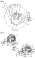
- Fig. 7 is a perspective view showing a suspension structure according to another embodiment. In order to facilitate understanding, only trailing arms and a cross beam are shown in Fig. 7 . Since the basic configuration as a trailing arm suspension device is the same as the above embodiment shown in Figs. 1 to 5 , description of the same portions will be omitted, and only the portions different from the above embodiment will be described below.
- Fig. 7 which is not part of the present invention is different from the above embodiment in that the rear end region of the trailing arm 12 is located above the in-wheel motor drive device 31 and faces the upper surface of the in-wheel motor drive device 31.
- the bracket 21 includes a projecting wall portion 22 projecting outward in the lateral direction of the vehicle from the rear end of the trailing arm 12, and a vertical wall portion 23 extending downward from the projecting wall portion 22.
- the end face 34s of the in-wheel motor drive device 31 matches a cutout portion 23c of the vertical wall portion 23 thus extending downward beyond the rear end region of the trailing arm 12.
- Bolts are inserted through a plurality of bolt holes 23h formed at intervals in the peripheral edge of the cutout portion 23c, and the tip ends of the bolts are tightened into internally threaded portions formed in the end face 34s.
- the in-wheel motor drive device 31 is thus coupled and fixed to the bracket 21.
- a coupling portion 25s that is coupled to the lower end of the shock absorber 42 is formed on the lower part of the rear wall portion 25.
- the coupling portion 25s is formed by a pair of tongues protruding from the rear wall portion 25 and facing each other. The coupling portion 25s receives the lower end of the shock absorber 42 between the pair of tongues.
- the rear end region of the trailing arm 12 extends linearly so as to be substantially horizontal.
- the central region of the trailing arm extends in a gently tilted manner with respect to the rear end region thereof such that the front end of the central region is lower than the rear end thereof.
- the front end region of the trailing arm 12 is located lower than the rear end region thereof and extends linearly so as to be substantially horizontal.
- the bracket 21 protrudes downward from the rear end region of the trailing arm 12.
- the in-wheel motor drive device is therefore placed below the rear end region of the trailing arm 12.
- the position of the pivot 14 in the lateral direction of the vehicle is included in the axial dimension A, B, and C as the range from the inner end to the outer end of the in-wheel motor drive device 31 in the lateral direction of the vehicle. Accordingly, the bending moment that is applied to the trailing arm 12 can be reduced even if the in-wheel motor drive device 31 is heavy.
- Fig. 8 is a perspective view showing a suspension structure according to still another embodiment. In order to facilitate understanding, only trailing arms and a cross beam are shown in Fig. 8 . Since the basic configuration as a trailing arm suspension device is the same as the above embodiment shown in Figs. 1 to 5 , description of the same portions will be omitted, and only the portions different from the above embodiment will be described below.
- the position of the in-wheel motor drive device in the longitudinal direction of the vehicle body is included in the range of the dimension of the rear end region of the trailing arm 12 in the longitudinal direction of the vehicle body.
- the embodiment shown in Fig. 8 is different from the above embodiments in that the in-wheel motor drive device is located rearward of the rear end of the trailing arm 12.
- the trailing arm 12 includes a reinforcing member 17 connected to the rear end of the trailing arm and extending in the vertical direction.
- the reinforcing member 17 is a pipe member having substantially the same shape in section as the trailing arm 12, and includes an upper portion 17a extending upward from the rear end of the trailing arm and a lower portion 17b extending downward from the rear end of the trailing arm.
- the trailing arm 12 except for the reinforcing member 17 extends horizontally.
- the bracket 21 includes a projecting wall portion 22 projecting outward in the lateral direction of the vehicle from the reinforcing member 17, a vertical wall portion 23 extending rearward from the projecting wall portion 22, an upper wall portion 28 bent at 90 degrees from the upper edge of the vertical wall portion 23 so as to extend in the lateral direction of the vehicle and connected to the upper end of the reinforcing member 17, and a lower wall portion 29 bent at 90 degrees from the lower edge of the vertical wall portion 23 so as to extend in the lateral direction of the vehicle and connected to the lower end of the reinforcing member 17.
- the vertical wall portion 23 is vertical to the ground and perpendicular to the lateral direction of the vehicle.
- the upper wall portion 28 and the lower wall portion 29 are substantially horizontal.
- a cutout 23c extending forward is formed in the rear edge of the vertical wall portion 23.
- a spring lower seat 16 is formed on the upper surface of the upper wall portion 28. The spring lower seat 16 is located at the upper end of the reinforcing member 17.
- the bracket 21 protrudes rearward of the rear end of the trailing arm 12.
- the in-wheel motor drive device is thus located rearward of the rear end of the trailing arm 12.
- the position of the pivot 14 in the lateral direction of the vehicle is included in the axial dimension A, B, and C as the range from the inner end to the outer end of the in-wheel motor drive device 31 in the lateral direction of the vehicle. Accordingly, the bending moment that is applied to the trailing arm 12 can be reduced even if the in-wheel motor drive device 31 is heavy.
- the suspension structure for the in-wheel motor drive device according to the present invention is advantageously used in electric and hybrid vehicles.
Landscapes
- Engineering & Computer Science (AREA)
- Mechanical Engineering (AREA)
- Chemical & Material Sciences (AREA)
- Combustion & Propulsion (AREA)
- Transportation (AREA)
- Vehicle Body Suspensions (AREA)
- Arrangement Or Mounting Of Propulsion Units For Vehicles (AREA)
Claims (4)
- Structure de suspension destinée à un dispositif d'entraînement intégré à une roue, comportant :une paire de bras oscillants (12) étant conçus pour s'étendre dans une direction longitudinale d'un véhicule et étant conçus pour être séparés l'un de l'autre dans une direction latérale dudit véhicule, chaque bras oscillant (12) comportant à son extrémité avant un pivot (14) qui est conçu pour être fixé à une carrosserie de véhicule,un élément formant poutre (13) étant conçu pour s'étendre dans ladite direction latérale dudit véhicule et reliant ladite paire de bras oscillants (12),un support (21) relié à une région d'extrémité arrière dudit bras oscillant (12), etun dispositif d'entraînement de moteur-roue (31) accouplé et fixé audit support (21), dans laquelle :ledit dispositif d'entraînement de moteur-roue (31) se situe au-dessus de ladite région d'extrémité arrière dudit bras oscillant (12), et un côté inférieur dudit dispositif d'entraînement de moteur-roue (31) est recouvert par ladite région d'extrémité arrière dudit bras oscillant (12) et ledit support (21),dans laquelle ledit support (21) est constitué d'une plaque de matériau, et comporte une partie paroi saillante (22) étant conçue pour faire saille vers l'extérieur dans ladite direction latérale dudit véhicule, depuis ladite région d'extrémité arrière dudit bras oscillant (12), une partie paroi verticale (23) s'étendant vers le haut depuis ladite partie paroi saillante (22),caractérisé en ce que le support comporte en outre une partie paroi avant (24) coudée à 90 degrés depuis le bord avant de la partie paroi verticale (23), de manière à s'étendre dans la direction latérale du véhicule et reliée à la région d'extrémité arrière du bras oscillant (12),et une partie paroi arrière (25) coudée à 90 degrés depuis le bord arrière de la partie paroi verticale (23), de manière à s'étendre dans la direction latérale du véhicule et reliée à l'extrémité arrière du bras oscillant (12),ladite partie paroi saillante (22) est conçue pour se situer entre ladite partie paroi avant (24) et ladite partie paroi arrière (25), telle que vue dans une direction verticale.
- Structure de suspension selon la revendication 1, dans laquelle :ladite partie paroi saillante (22) comporte un trou d'évacuation (26, 27) s'étendant au travers de celle-ci dans une direction verticale.
- Structure de suspension selon l'une quelconque des revendications 1 et 2, dans laquelle :
ladite région d'extrémité arrière dudit bras oscillant (12) comporte, à une position, dans ladite direction longitudinale dudit véhicule, qui est comprise dans une plage allant d'une extrémité avant à une extrémité arrière dudit support (21) dans ladite direction longitudinale dudit véhicule, une partie d'accouplement (18) qui est accouplée à une extrémité inférieure d'un amortisseur s'étendant à partir de ladite carrosserie de véhicule. - Structure de suspension selon l'une quelconque des revendications 1 à 3, dans laquelle :
ladite région d'extrémité arrière dudit bras oscillant (12) s'étend de manière linéaire, de façon à être sensiblement horizontale, et une région centrale dudit bras oscillant (12) s'étend de manière légèrement inclinée par rapport à ladite région d'extrémité arrière, de façon qu'une extrémité avant de ladite région centrale soit plus haute que son extrémité arrière.
Applications Claiming Priority (2)
| Application Number | Priority Date | Filing Date | Title |
|---|---|---|---|
| JP2012200843A JP5932582B2 (ja) | 2012-09-12 | 2012-09-12 | インホイールモータ駆動装置のサスペンション構造 |
| PCT/JP2013/073540 WO2014042030A1 (fr) | 2012-09-12 | 2013-09-02 | Structure de suspension pour dispositif d'entraînement de moteur-roue |
Publications (3)
| Publication Number | Publication Date |
|---|---|
| EP2896519A1 EP2896519A1 (fr) | 2015-07-22 |
| EP2896519A4 EP2896519A4 (fr) | 2016-04-13 |
| EP2896519B1 true EP2896519B1 (fr) | 2018-10-31 |
Family
ID=50278147
Family Applications (1)
| Application Number | Title | Priority Date | Filing Date |
|---|---|---|---|
| EP13836890.7A Not-in-force EP2896519B1 (fr) | 2012-09-12 | 2013-09-02 | Structure de suspension pour dispositif d'entraînement de moteur-roue |
Country Status (6)
| Country | Link |
|---|---|
| US (1) | US9771105B2 (fr) |
| EP (1) | EP2896519B1 (fr) |
| JP (1) | JP5932582B2 (fr) |
| CN (1) | CN104619527B (fr) |
| IN (1) | IN2015MN00451A (fr) |
| WO (1) | WO2014042030A1 (fr) |
Families Citing this family (14)
| Publication number | Priority date | Publication date | Assignee | Title |
|---|---|---|---|---|
| JP5932581B2 (ja) * | 2012-09-12 | 2016-06-08 | Ntn株式会社 | インホイールモータ駆動装置のサスペンション構造 |
| DE102015213357B4 (de) * | 2015-07-16 | 2018-02-08 | Zf Friedrichshafen Ag | Antreibbare Verbundlenkerachse mit einem Querprofil und jeweils endseitig des Querprofils damit verbundenen Längslenkern |
| DE102015213356A1 (de) * | 2015-07-16 | 2017-01-19 | Zf Friedrichshafen Ag | Antreibbare Verbundlenkerachse eines Fahrzeuges mit zwei Längslenkern |
| JP6853622B2 (ja) * | 2015-09-29 | 2021-03-31 | Ntn株式会社 | インホイールモータ駆動装置、およびインホイールモータ駆動装置とサスペンション装置の連結構造 |
| US9944327B2 (en) * | 2016-09-15 | 2018-04-17 | Kawasaki Jukogyo Kabushiki Kaisha | Utility vehicle |
| DE112017006775T5 (de) * | 2017-01-10 | 2019-10-31 | F-Tech Inc. | Motorantriebsvorrichtung |
| DE102018103885B4 (de) * | 2017-04-13 | 2020-07-23 | Benteler Automobiltechnik Gmbh | Kraftfahrzeugachse mit Elektroantrieb |
| JP6891783B2 (ja) | 2017-12-04 | 2021-06-18 | トヨタ自動車株式会社 | インホイールモータユニットの取付構造 |
| USD883864S1 (en) | 2018-05-10 | 2020-05-12 | Allison Transmission, Inc. | Axle assembly |
| JP7127478B2 (ja) * | 2018-10-23 | 2022-08-30 | トヨタ自動車株式会社 | サスペンション装置、車両 |
| DE102019111714A1 (de) * | 2019-05-06 | 2020-11-12 | Universität Siegen | Hinterachse für ein zweispuriges Fahrzeug und zweispuriges Fahrzeug mit einer Hinterachse |
| CN111923721B (zh) * | 2019-10-24 | 2022-04-29 | 中国北方车辆研究所 | 一种单纵臂轮毂电机驱动模块 |
| CN111873790B (zh) * | 2020-07-15 | 2021-08-20 | 长城汽车股份有限公司 | 前减速器安装支架组件和车辆 |
| JP7533387B2 (ja) * | 2021-07-08 | 2024-08-14 | トヨタ自動車株式会社 | トーションビーム式サスペンション |
Family Cites Families (26)
| Publication number | Priority date | Publication date | Assignee | Title |
|---|---|---|---|---|
| US3937291A (en) * | 1974-10-07 | 1976-02-10 | Corbin Gentry, Inc. | Motor mount for electric powered motorcycle |
| CA2078014A1 (fr) * | 1991-09-18 | 1993-03-19 | Donald L. Stephens | Systeme de suspension leger pour vehicule a roues, bras de suspension et methode de fabrication |
| JP3136346B2 (ja) | 1994-11-01 | 2001-02-19 | ダイハツ工業株式会社 | トレーリングアーム式サスペンション |
| US5524726A (en) * | 1995-04-18 | 1996-06-11 | Tenergy L.L.C. | Swing arm supported electrical drive assembly for powering cycles |
| US5924504A (en) * | 1997-02-18 | 1999-07-20 | Meritor Heavy Vehicle Systems, Llc | Suspension drive unit assembly for an electrically driven vehicle |
| DE19932586A1 (de) * | 1999-07-13 | 2001-04-12 | Zahnradfabrik Friedrichshafen | Achse mit einer unterhalb der Radachse angeordneten Achsbrücke |
| JP2002337554A (ja) * | 2001-05-16 | 2002-11-27 | Mazda Motor Corp | 車両の駆動装置配設構造 |
| JP2005153557A (ja) * | 2003-11-20 | 2005-06-16 | Ntn Corp | 自動車のモータ駆動システム |
| JP4276579B2 (ja) * | 2004-05-17 | 2009-06-10 | トヨタ自動車株式会社 | インホイールモータに設けられる部品の搭載構造 |
| JP4694147B2 (ja) * | 2004-05-26 | 2011-06-08 | トヨタ自動車株式会社 | 車輪支持装置 |
| JP2006027310A (ja) | 2004-07-12 | 2006-02-02 | Nissan Motor Co Ltd | 車両用インホイールモータの支持構造 |
| JP4360305B2 (ja) * | 2004-08-25 | 2009-11-11 | トヨタ自動車株式会社 | インホイールモータのハウジング構造 |
| JP4656998B2 (ja) | 2005-04-22 | 2011-03-23 | トヨタ自動車株式会社 | インホイールモータの冷却構造 |
| US7501732B2 (en) * | 2005-05-30 | 2009-03-10 | Denso Corporation | Electric rotating machine |
| WO2007015554A1 (fr) * | 2005-08-01 | 2007-02-08 | Hitachi Construction Machinery Co., Ltd. | Dispositif de rotation de tambour pour engin de chantier |
| JP2007099114A (ja) * | 2005-10-05 | 2007-04-19 | Nissan Motor Co Ltd | ホイールインモータの取り付け構造 |
| US7651153B2 (en) * | 2006-07-18 | 2010-01-26 | Unicell Limited | Delivery vehicle |
| JP2010069963A (ja) * | 2008-09-16 | 2010-04-02 | Asahi Tec Corp | トレーリング部材およびトーションビーム式サスペンション |
| CN102216096B (zh) * | 2008-09-26 | 2013-09-25 | M.B.格瑞德V/迈尔斯B.格瑞德公司 | 车辆悬架 |
| JP5292626B2 (ja) | 2008-11-12 | 2013-09-18 | Ntn株式会社 | インホイールモータ駆動装置およびインホイールモータ駆動装置用ケーシング |
| JP2010228544A (ja) * | 2009-03-26 | 2010-10-14 | Nissan Motor Co Ltd | 車両用サスペンション装置 |
| KR101104006B1 (ko) * | 2009-12-03 | 2012-01-06 | 현대자동차주식회사 | 차량의 리어 서스펜션 |
| US20120292978A1 (en) * | 2010-02-07 | 2012-11-22 | Ksm Castings Gmbh | Axle module |
| DE102011005625A1 (de) * | 2011-03-16 | 2012-09-20 | Zf Friedrichshafen Ag | Antriebsvorrichtung zum Antreiben eines Rades einer Verbundlenkerachse für ein elektrisch antreibbares Fahrzeug |
| KR101301754B1 (ko) * | 2011-05-23 | 2013-08-29 | 현대모비스 주식회사 | 인휠 구동장치 |
| JP5932581B2 (ja) * | 2012-09-12 | 2016-06-08 | Ntn株式会社 | インホイールモータ駆動装置のサスペンション構造 |
-
2012
- 2012-09-12 JP JP2012200843A patent/JP5932582B2/ja not_active Expired - Fee Related
-
2013
- 2013-09-02 EP EP13836890.7A patent/EP2896519B1/fr not_active Not-in-force
- 2013-09-02 WO PCT/JP2013/073540 patent/WO2014042030A1/fr active Application Filing
- 2013-09-02 US US14/427,746 patent/US9771105B2/en active Active
- 2013-09-02 CN CN201380047324.4A patent/CN104619527B/zh not_active Expired - Fee Related
- 2013-09-02 IN IN451MUN2015 patent/IN2015MN00451A/en unknown
Non-Patent Citations (1)
| Title |
|---|
| None * |
Also Published As
| Publication number | Publication date |
|---|---|
| EP2896519A4 (fr) | 2016-04-13 |
| US9771105B2 (en) | 2017-09-26 |
| EP2896519A1 (fr) | 2015-07-22 |
| JP2014054918A (ja) | 2014-03-27 |
| IN2015MN00451A (fr) | 2015-09-04 |
| JP5932582B2 (ja) | 2016-06-08 |
| WO2014042030A1 (fr) | 2014-03-20 |
| CN104619527B (zh) | 2017-03-22 |
| CN104619527A (zh) | 2015-05-13 |
| US20150203159A1 (en) | 2015-07-23 |
Similar Documents
| Publication | Publication Date | Title |
|---|---|---|
| EP2896519B1 (fr) | Structure de suspension pour dispositif d'entraînement de moteur-roue | |
| EP2896520B1 (fr) | Structure de suspension pour dispositif d'entraînement de moteur-roue | |
| EP3112194B1 (fr) | Structure pour relier un dispositif d'entraînement à moteur dans une roue et un amortisseur, et dispositif de suspension comportant ladite structure de liaison | |
| US9796235B2 (en) | Suspension device for in-wheel motor driven wheel | |
| EP2993066B1 (fr) | Dispositif de suspension de roue menée de moteur-roue | |
| EP3047996B1 (fr) | Dispositif d'entraînement à moteur dans une roue | |
| EP2960542A1 (fr) | Amortisseur de chocs | |
| EP3017988B1 (fr) | Structure de routage de câblages d'alimentation de moteur pour roue entrainée par un moteur-roue | |
| CN107571698B (zh) | 汽车的前悬架构造 | |
| US10723288B2 (en) | Wiring structure for in-wheel motor power line, and in-wheel motor drive device | |
| EP3287306B1 (fr) | Structure de suspension de véhicule | |
| JP2014054920A (ja) | インホイールモータ駆動装置のサスペンション構造 | |
| EP3441251B1 (fr) | Structure de câblage pour ligne d'alimentation de moteur-roue, et dispositif d'entraînement de moteur-roue | |
| JP5978077B2 (ja) | インホイールモータ駆動装置のサスペンション構造 | |
| KR20100048158A (ko) | 액티브 지오메트리 컨트롤 서스펜션 | |
| JP5556447B2 (ja) | 車両用サスペンション装置 | |
| JP5617750B2 (ja) | 車両用懸架装置 | |
| WO2020145272A1 (fr) | Structure de suspension pour dispositif d'entraînement de moteur-roue | |
| KR20040073026A (ko) | 스트러트와 너클의 체결 구조 |
Legal Events
| Date | Code | Title | Description |
|---|---|---|---|
| PUAI | Public reference made under article 153(3) epc to a published international application that has entered the european phase |
Free format text: ORIGINAL CODE: 0009012 |
|
| 17P | Request for examination filed |
Effective date: 20150309 |
|
| AK | Designated contracting states |
Kind code of ref document: A1 Designated state(s): AL AT BE BG CH CY CZ DE DK EE ES FI FR GB GR HR HU IE IS IT LI LT LU LV MC MK MT NL NO PL PT RO RS SE SI SK SM TR |
|
| AX | Request for extension of the european patent |
Extension state: BA ME |
|
| DAX | Request for extension of the european patent (deleted) | ||
| RA4 | Supplementary search report drawn up and despatched (corrected) |
Effective date: 20160315 |
|
| RIC1 | Information provided on ipc code assigned before grant |
Ipc: B60G 9/04 20060101AFI20160309BHEP Ipc: B60K 7/00 20060101ALI20160309BHEP Ipc: B60G 21/05 20060101ALI20160309BHEP Ipc: B60K 17/04 20060101ALI20160309BHEP Ipc: B62D 21/11 20060101ALI20160309BHEP |
|
| STAA | Information on the status of an ep patent application or granted ep patent |
Free format text: STATUS: EXAMINATION IS IN PROGRESS |
|
| 17Q | First examination report despatched |
Effective date: 20170330 |
|
| GRAP | Despatch of communication of intention to grant a patent |
Free format text: ORIGINAL CODE: EPIDOSNIGR1 |
|
| STAA | Information on the status of an ep patent application or granted ep patent |
Free format text: STATUS: GRANT OF PATENT IS INTENDED |
|
| INTG | Intention to grant announced |
Effective date: 20180419 |
|
| GRAS | Grant fee paid |
Free format text: ORIGINAL CODE: EPIDOSNIGR3 |
|
| GRAA | (expected) grant |
Free format text: ORIGINAL CODE: 0009210 |
|
| STAA | Information on the status of an ep patent application or granted ep patent |
Free format text: STATUS: THE PATENT HAS BEEN GRANTED |
|
| AK | Designated contracting states |
Kind code of ref document: B1 Designated state(s): AL AT BE BG CH CY CZ DE DK EE ES FI FR GB GR HR HU IE IS IT LI LT LU LV MC MK MT NL NO PL PT RO RS SE SI SK SM TR |
|
| REG | Reference to a national code |
Ref country code: CH Ref legal event code: EP Ref country code: GB Ref legal event code: FG4D |
|
| REG | Reference to a national code |
Ref country code: AT Ref legal event code: REF Ref document number: 1058928 Country of ref document: AT Kind code of ref document: T Effective date: 20181115 |
|
| REG | Reference to a national code |
Ref country code: IE Ref legal event code: FG4D |
|
| REG | Reference to a national code |
Ref country code: DE Ref legal event code: R096 Ref document number: 602013046094 Country of ref document: DE |
|
| REG | Reference to a national code |
Ref country code: NL Ref legal event code: MP Effective date: 20181031 |
|
| REG | Reference to a national code |
Ref country code: LT Ref legal event code: MG4D |
|
| REG | Reference to a national code |
Ref country code: AT Ref legal event code: MK05 Ref document number: 1058928 Country of ref document: AT Kind code of ref document: T Effective date: 20181031 |
|
| PG25 | Lapsed in a contracting state [announced via postgrant information from national office to epo] |
Ref country code: FI Free format text: LAPSE BECAUSE OF FAILURE TO SUBMIT A TRANSLATION OF THE DESCRIPTION OR TO PAY THE FEE WITHIN THE PRESCRIBED TIME-LIMIT Effective date: 20181031 Ref country code: LV Free format text: LAPSE BECAUSE OF FAILURE TO SUBMIT A TRANSLATION OF THE DESCRIPTION OR TO PAY THE FEE WITHIN THE PRESCRIBED TIME-LIMIT Effective date: 20181031 Ref country code: HR Free format text: LAPSE BECAUSE OF FAILURE TO SUBMIT A TRANSLATION OF THE DESCRIPTION OR TO PAY THE FEE WITHIN THE PRESCRIBED TIME-LIMIT Effective date: 20181031 Ref country code: IS Free format text: LAPSE BECAUSE OF FAILURE TO SUBMIT A TRANSLATION OF THE DESCRIPTION OR TO PAY THE FEE WITHIN THE PRESCRIBED TIME-LIMIT Effective date: 20190228 Ref country code: PL Free format text: LAPSE BECAUSE OF FAILURE TO SUBMIT A TRANSLATION OF THE DESCRIPTION OR TO PAY THE FEE WITHIN THE PRESCRIBED TIME-LIMIT Effective date: 20181031 Ref country code: AT Free format text: LAPSE BECAUSE OF FAILURE TO SUBMIT A TRANSLATION OF THE DESCRIPTION OR TO PAY THE FEE WITHIN THE PRESCRIBED TIME-LIMIT Effective date: 20181031 Ref country code: BG Free format text: LAPSE BECAUSE OF FAILURE TO SUBMIT A TRANSLATION OF THE DESCRIPTION OR TO PAY THE FEE WITHIN THE PRESCRIBED TIME-LIMIT Effective date: 20190131 Ref country code: NO Free format text: LAPSE BECAUSE OF FAILURE TO SUBMIT A TRANSLATION OF THE DESCRIPTION OR TO PAY THE FEE WITHIN THE PRESCRIBED TIME-LIMIT Effective date: 20190131 Ref country code: ES Free format text: LAPSE BECAUSE OF FAILURE TO SUBMIT A TRANSLATION OF THE DESCRIPTION OR TO PAY THE FEE WITHIN THE PRESCRIBED TIME-LIMIT Effective date: 20181031 Ref country code: LT Free format text: LAPSE BECAUSE OF FAILURE TO SUBMIT A TRANSLATION OF THE DESCRIPTION OR TO PAY THE FEE WITHIN THE PRESCRIBED TIME-LIMIT Effective date: 20181031 |
|
| PG25 | Lapsed in a contracting state [announced via postgrant information from national office to epo] |
Ref country code: AL Free format text: LAPSE BECAUSE OF FAILURE TO SUBMIT A TRANSLATION OF THE DESCRIPTION OR TO PAY THE FEE WITHIN THE PRESCRIBED TIME-LIMIT Effective date: 20181031 Ref country code: NL Free format text: LAPSE BECAUSE OF FAILURE TO SUBMIT A TRANSLATION OF THE DESCRIPTION OR TO PAY THE FEE WITHIN THE PRESCRIBED TIME-LIMIT Effective date: 20181031 Ref country code: PT Free format text: LAPSE BECAUSE OF FAILURE TO SUBMIT A TRANSLATION OF THE DESCRIPTION OR TO PAY THE FEE WITHIN THE PRESCRIBED TIME-LIMIT Effective date: 20190301 Ref country code: SE Free format text: LAPSE BECAUSE OF FAILURE TO SUBMIT A TRANSLATION OF THE DESCRIPTION OR TO PAY THE FEE WITHIN THE PRESCRIBED TIME-LIMIT Effective date: 20181031 Ref country code: RS Free format text: LAPSE BECAUSE OF FAILURE TO SUBMIT A TRANSLATION OF THE DESCRIPTION OR TO PAY THE FEE WITHIN THE PRESCRIBED TIME-LIMIT Effective date: 20181031 Ref country code: GR Free format text: LAPSE BECAUSE OF FAILURE TO SUBMIT A TRANSLATION OF THE DESCRIPTION OR TO PAY THE FEE WITHIN THE PRESCRIBED TIME-LIMIT Effective date: 20190201 |
|
| PG25 | Lapsed in a contracting state [announced via postgrant information from national office to epo] |
Ref country code: CZ Free format text: LAPSE BECAUSE OF FAILURE TO SUBMIT A TRANSLATION OF THE DESCRIPTION OR TO PAY THE FEE WITHIN THE PRESCRIBED TIME-LIMIT Effective date: 20181031 Ref country code: IT Free format text: LAPSE BECAUSE OF FAILURE TO SUBMIT A TRANSLATION OF THE DESCRIPTION OR TO PAY THE FEE WITHIN THE PRESCRIBED TIME-LIMIT Effective date: 20181031 Ref country code: DK Free format text: LAPSE BECAUSE OF FAILURE TO SUBMIT A TRANSLATION OF THE DESCRIPTION OR TO PAY THE FEE WITHIN THE PRESCRIBED TIME-LIMIT Effective date: 20181031 |
|
| REG | Reference to a national code |
Ref country code: DE Ref legal event code: R097 Ref document number: 602013046094 Country of ref document: DE |
|
| PG25 | Lapsed in a contracting state [announced via postgrant information from national office to epo] |
Ref country code: EE Free format text: LAPSE BECAUSE OF FAILURE TO SUBMIT A TRANSLATION OF THE DESCRIPTION OR TO PAY THE FEE WITHIN THE PRESCRIBED TIME-LIMIT Effective date: 20181031 Ref country code: SM Free format text: LAPSE BECAUSE OF FAILURE TO SUBMIT A TRANSLATION OF THE DESCRIPTION OR TO PAY THE FEE WITHIN THE PRESCRIBED TIME-LIMIT Effective date: 20181031 Ref country code: SK Free format text: LAPSE BECAUSE OF FAILURE TO SUBMIT A TRANSLATION OF THE DESCRIPTION OR TO PAY THE FEE WITHIN THE PRESCRIBED TIME-LIMIT Effective date: 20181031 Ref country code: RO Free format text: LAPSE BECAUSE OF FAILURE TO SUBMIT A TRANSLATION OF THE DESCRIPTION OR TO PAY THE FEE WITHIN THE PRESCRIBED TIME-LIMIT Effective date: 20181031 |
|
| PLBE | No opposition filed within time limit |
Free format text: ORIGINAL CODE: 0009261 |
|
| STAA | Information on the status of an ep patent application or granted ep patent |
Free format text: STATUS: NO OPPOSITION FILED WITHIN TIME LIMIT |
|
| 26N | No opposition filed |
Effective date: 20190801 |
|
| PG25 | Lapsed in a contracting state [announced via postgrant information from national office to epo] |
Ref country code: SI Free format text: LAPSE BECAUSE OF FAILURE TO SUBMIT A TRANSLATION OF THE DESCRIPTION OR TO PAY THE FEE WITHIN THE PRESCRIBED TIME-LIMIT Effective date: 20181031 |
|
| PG25 | Lapsed in a contracting state [announced via postgrant information from national office to epo] |
Ref country code: TR Free format text: LAPSE BECAUSE OF FAILURE TO SUBMIT A TRANSLATION OF THE DESCRIPTION OR TO PAY THE FEE WITHIN THE PRESCRIBED TIME-LIMIT Effective date: 20181031 |
|
| PG25 | Lapsed in a contracting state [announced via postgrant information from national office to epo] |
Ref country code: MC Free format text: LAPSE BECAUSE OF FAILURE TO SUBMIT A TRANSLATION OF THE DESCRIPTION OR TO PAY THE FEE WITHIN THE PRESCRIBED TIME-LIMIT Effective date: 20181031 |
|
| REG | Reference to a national code |
Ref country code: CH Ref legal event code: PL |
|
| PG25 | Lapsed in a contracting state [announced via postgrant information from national office to epo] |
Ref country code: CH Free format text: LAPSE BECAUSE OF NON-PAYMENT OF DUE FEES Effective date: 20190930 Ref country code: LI Free format text: LAPSE BECAUSE OF NON-PAYMENT OF DUE FEES Effective date: 20190930 Ref country code: IE Free format text: LAPSE BECAUSE OF NON-PAYMENT OF DUE FEES Effective date: 20190902 Ref country code: LU Free format text: LAPSE BECAUSE OF NON-PAYMENT OF DUE FEES Effective date: 20190902 |
|
| REG | Reference to a national code |
Ref country code: BE Ref legal event code: MM Effective date: 20190930 |
|
| PG25 | Lapsed in a contracting state [announced via postgrant information from national office to epo] |
Ref country code: BE Free format text: LAPSE BECAUSE OF NON-PAYMENT OF DUE FEES Effective date: 20190930 |
|
| GBPC | Gb: european patent ceased through non-payment of renewal fee |
Effective date: 20190902 |
|
| PG25 | Lapsed in a contracting state [announced via postgrant information from national office to epo] |
Ref country code: GB Free format text: LAPSE BECAUSE OF NON-PAYMENT OF DUE FEES Effective date: 20190902 |
|
| PG25 | Lapsed in a contracting state [announced via postgrant information from national office to epo] |
Ref country code: CY Free format text: LAPSE BECAUSE OF FAILURE TO SUBMIT A TRANSLATION OF THE DESCRIPTION OR TO PAY THE FEE WITHIN THE PRESCRIBED TIME-LIMIT Effective date: 20181031 |
|
| PG25 | Lapsed in a contracting state [announced via postgrant information from national office to epo] |
Ref country code: HU Free format text: LAPSE BECAUSE OF FAILURE TO SUBMIT A TRANSLATION OF THE DESCRIPTION OR TO PAY THE FEE WITHIN THE PRESCRIBED TIME-LIMIT; INVALID AB INITIO Effective date: 20130902 Ref country code: MT Free format text: LAPSE BECAUSE OF FAILURE TO SUBMIT A TRANSLATION OF THE DESCRIPTION OR TO PAY THE FEE WITHIN THE PRESCRIBED TIME-LIMIT Effective date: 20181031 |
|
| PGFP | Annual fee paid to national office [announced via postgrant information from national office to epo] |
Ref country code: FR Payment date: 20210812 Year of fee payment: 9 |
|
| PGFP | Annual fee paid to national office [announced via postgrant information from national office to epo] |
Ref country code: DE Payment date: 20210727 Year of fee payment: 9 |
|
| PG25 | Lapsed in a contracting state [announced via postgrant information from national office to epo] |
Ref country code: MK Free format text: LAPSE BECAUSE OF FAILURE TO SUBMIT A TRANSLATION OF THE DESCRIPTION OR TO PAY THE FEE WITHIN THE PRESCRIBED TIME-LIMIT Effective date: 20181031 |
|
| REG | Reference to a national code |
Ref country code: DE Ref legal event code: R119 Ref document number: 602013046094 Country of ref document: DE |
|
| PG25 | Lapsed in a contracting state [announced via postgrant information from national office to epo] |
Ref country code: FR Free format text: LAPSE BECAUSE OF NON-PAYMENT OF DUE FEES Effective date: 20220930 Ref country code: DE Free format text: LAPSE BECAUSE OF NON-PAYMENT OF DUE FEES Effective date: 20230401 |