EP2890490B1 - Ensemble formant réacteur et procédé de polymérisation d'oléfine - Google Patents
Ensemble formant réacteur et procédé de polymérisation d'oléfine Download PDFInfo
- Publication number
- EP2890490B1 EP2890490B1 EP13755970.4A EP13755970A EP2890490B1 EP 2890490 B1 EP2890490 B1 EP 2890490B1 EP 13755970 A EP13755970 A EP 13755970A EP 2890490 B1 EP2890490 B1 EP 2890490B1
- Authority
- EP
- European Patent Office
- Prior art keywords
- gas
- stream
- fluidized bed
- flow
- bed reactor
- Prior art date
- Legal status (The legal status is an assumption and is not a legal conclusion. Google has not performed a legal analysis and makes no representation as to the accuracy of the status listed.)
- Active
Links
- 238000000034 method Methods 0.000 title claims description 56
- 150000001336 alkenes Chemical class 0.000 title claims description 9
- 238000006116 polymerization reaction Methods 0.000 title description 20
- 239000007789 gas Substances 0.000 claims description 421
- 239000007787 solid Substances 0.000 claims description 405
- 238000005243 fluidization Methods 0.000 claims description 170
- 238000000926 separation method Methods 0.000 claims description 166
- 238000004064 recycling Methods 0.000 claims description 149
- 239000002245 particle Substances 0.000 claims description 104
- 229920000642 polymer Polymers 0.000 claims description 88
- 238000011143 downstream manufacturing Methods 0.000 claims description 50
- 238000009826 distribution Methods 0.000 claims description 34
- 239000000203 mixture Substances 0.000 claims description 16
- 230000003247 decreasing effect Effects 0.000 claims description 13
- 238000004519 manufacturing process Methods 0.000 claims description 12
- JTJMJGYZQZDUJJ-UHFFFAOYSA-N phencyclidine Chemical class C1CCCCN1C1(C=2C=CC=CC=2)CCCCC1 JTJMJGYZQZDUJJ-UHFFFAOYSA-N 0.000 claims description 10
- 238000005259 measurement Methods 0.000 claims description 8
- 239000012530 fluid Substances 0.000 claims description 6
- 238000011027 product recovery Methods 0.000 claims description 5
- 230000000379 polymerizing effect Effects 0.000 claims description 4
- 230000000630 rising effect Effects 0.000 claims description 4
- 238000012545 processing Methods 0.000 claims description 2
- 239000003054 catalyst Substances 0.000 description 29
- 230000008569 process Effects 0.000 description 25
- 238000011144 upstream manufacturing Methods 0.000 description 25
- 238000006243 chemical reaction Methods 0.000 description 10
- VGGSQFUCUMXWEO-UHFFFAOYSA-N Ethene Chemical compound C=C VGGSQFUCUMXWEO-UHFFFAOYSA-N 0.000 description 8
- 239000005977 Ethylene Substances 0.000 description 8
- 230000015572 biosynthetic process Effects 0.000 description 8
- 238000001816 cooling Methods 0.000 description 8
- 239000002685 polymerization catalyst Substances 0.000 description 7
- VXNZUUAINFGPBY-UHFFFAOYSA-N 1-Butene Chemical compound CCC=C VXNZUUAINFGPBY-UHFFFAOYSA-N 0.000 description 6
- IJGRMHOSHXDMSA-UHFFFAOYSA-N Atomic nitrogen Chemical compound N#N IJGRMHOSHXDMSA-UHFFFAOYSA-N 0.000 description 6
- KFZMGEQAYNKOFK-UHFFFAOYSA-N Isopropanol Chemical compound CC(C)O KFZMGEQAYNKOFK-UHFFFAOYSA-N 0.000 description 6
- 238000004458 analytical method Methods 0.000 description 6
- 230000007423 decrease Effects 0.000 description 6
- 238000013461 design Methods 0.000 description 6
- 239000000178 monomer Substances 0.000 description 6
- 239000000843 powder Substances 0.000 description 6
- OFBQJSOFQDEBGM-UHFFFAOYSA-N Pentane Chemical compound CCCCC OFBQJSOFQDEBGM-UHFFFAOYSA-N 0.000 description 5
- 230000008901 benefit Effects 0.000 description 5
- 230000009977 dual effect Effects 0.000 description 5
- 229920000098 polyolefin Polymers 0.000 description 5
- ATUOYWHBWRKTHZ-UHFFFAOYSA-N Propane Chemical compound CCC ATUOYWHBWRKTHZ-UHFFFAOYSA-N 0.000 description 4
- 230000000712 assembly Effects 0.000 description 4
- 238000000429 assembly Methods 0.000 description 4
- 230000005587 bubbling Effects 0.000 description 4
- 239000000839 emulsion Substances 0.000 description 4
- 238000005516 engineering process Methods 0.000 description 4
- -1 ethylene, propylene, 1-butene Chemical class 0.000 description 4
- 239000001257 hydrogen Substances 0.000 description 4
- 229910052739 hydrogen Inorganic materials 0.000 description 4
- 238000002347 injection Methods 0.000 description 4
- 239000007924 injection Substances 0.000 description 4
- NNPPMTNAJDCUHE-UHFFFAOYSA-N isobutane Chemical compound CC(C)C NNPPMTNAJDCUHE-UHFFFAOYSA-N 0.000 description 4
- QWTDNUCVQCZILF-UHFFFAOYSA-N isopentane Chemical compound CCC(C)C QWTDNUCVQCZILF-UHFFFAOYSA-N 0.000 description 4
- 239000000463 material Substances 0.000 description 4
- 235000020030 perry Nutrition 0.000 description 4
- UFHFLCQGNIYNRP-UHFFFAOYSA-N Hydrogen Chemical compound [H][H] UFHFLCQGNIYNRP-UHFFFAOYSA-N 0.000 description 3
- 125000000205 L-threonino group Chemical group [H]OC(=O)[C@@]([H])(N([H])[*])[C@](C([H])([H])[H])([H])O[H] 0.000 description 3
- 239000012190 activator Substances 0.000 description 3
- 239000000654 additive Substances 0.000 description 3
- 239000003795 chemical substances by application Substances 0.000 description 3
- 238000004891 communication Methods 0.000 description 3
- 239000011261 inert gas Substances 0.000 description 3
- IJDNQMDRQITEOD-UHFFFAOYSA-N n-butane Chemical compound CCCC IJDNQMDRQITEOD-UHFFFAOYSA-N 0.000 description 3
- 229910052757 nitrogen Inorganic materials 0.000 description 3
- JRZJOMJEPLMPRA-UHFFFAOYSA-N olefin Natural products CCCCCCCC=C JRZJOMJEPLMPRA-UHFFFAOYSA-N 0.000 description 3
- 239000011343 solid material Substances 0.000 description 3
- 239000004711 α-olefin Substances 0.000 description 3
- ZGEGCLOFRBLKSE-UHFFFAOYSA-N 1-Heptene Chemical compound CCCCCC=C ZGEGCLOFRBLKSE-UHFFFAOYSA-N 0.000 description 2
- AFFLGGQVNFXPEV-UHFFFAOYSA-N 1-decene Chemical compound CCCCCCCCC=C AFFLGGQVNFXPEV-UHFFFAOYSA-N 0.000 description 2
- LIKMAJRDDDTEIG-UHFFFAOYSA-N 1-hexene Chemical compound CCCCC=C LIKMAJRDDDTEIG-UHFFFAOYSA-N 0.000 description 2
- KWKAKUADMBZCLK-UHFFFAOYSA-N 1-octene Chemical compound CCCCCCC=C KWKAKUADMBZCLK-UHFFFAOYSA-N 0.000 description 2
- WSSSPWUEQFSQQG-UHFFFAOYSA-N 4-methyl-1-pentene Chemical compound CC(C)CC=C WSSSPWUEQFSQQG-UHFFFAOYSA-N 0.000 description 2
- KAKZBPTYRLMSJV-UHFFFAOYSA-N Butadiene Chemical compound C=CC=C KAKZBPTYRLMSJV-UHFFFAOYSA-N 0.000 description 2
- OTMSDBZUPAUEDD-UHFFFAOYSA-N Ethane Chemical compound CC OTMSDBZUPAUEDD-UHFFFAOYSA-N 0.000 description 2
- PPBRXRYQALVLMV-UHFFFAOYSA-N Styrene Chemical compound C=CC1=CC=CC=C1 PPBRXRYQALVLMV-UHFFFAOYSA-N 0.000 description 2
- 239000004411 aluminium Substances 0.000 description 2
- 229910052782 aluminium Inorganic materials 0.000 description 2
- XAGFODPZIPBFFR-UHFFFAOYSA-N aluminium Chemical compound [Al] XAGFODPZIPBFFR-UHFFFAOYSA-N 0.000 description 2
- 238000004364 calculation method Methods 0.000 description 2
- 125000004432 carbon atom Chemical group C* 0.000 description 2
- 239000007795 chemical reaction product Substances 0.000 description 2
- 238000010276 construction Methods 0.000 description 2
- AFABGHUZZDYHJO-UHFFFAOYSA-N dimethyl butane Natural products CCCC(C)C AFABGHUZZDYHJO-UHFFFAOYSA-N 0.000 description 2
- 239000001282 iso-butane Substances 0.000 description 2
- 239000012968 metallocene catalyst Substances 0.000 description 2
- VNWKTOKETHGBQD-UHFFFAOYSA-N methane Chemical compound C VNWKTOKETHGBQD-UHFFFAOYSA-N 0.000 description 2
- VLKZOEOYAKHREP-UHFFFAOYSA-N n-Hexane Chemical compound CCCCCC VLKZOEOYAKHREP-UHFFFAOYSA-N 0.000 description 2
- 239000008188 pellet Substances 0.000 description 2
- YWAKXRMUMFPDSH-UHFFFAOYSA-N pentene Chemical compound CCCC=C YWAKXRMUMFPDSH-UHFFFAOYSA-N 0.000 description 2
- 239000000047 product Substances 0.000 description 2
- 239000001294 propane Substances 0.000 description 2
- QQONPFPTGQHPMA-UHFFFAOYSA-N propylene Natural products CC=C QQONPFPTGQHPMA-UHFFFAOYSA-N 0.000 description 2
- 125000004805 propylene group Chemical group [H]C([H])([H])C([H])([*:1])C([H])([H])[*:2] 0.000 description 2
- 230000002285 radioactive effect Effects 0.000 description 2
- 230000009467 reduction Effects 0.000 description 2
- 239000000126 substance Substances 0.000 description 2
- 230000002195 synergetic effect Effects 0.000 description 2
- 238000012546 transfer Methods 0.000 description 2
- PRBHEGAFLDMLAL-GQCTYLIASA-N (4e)-hexa-1,4-diene Chemical compound C\C=C\CC=C PRBHEGAFLDMLAL-GQCTYLIASA-N 0.000 description 1
- VMTIBEFOMPMORT-UHFFFAOYSA-N 4-methylocta-1,7-diene Chemical compound C=CCC(C)CCC=C VMTIBEFOMPMORT-UHFFFAOYSA-N 0.000 description 1
- INYHZQLKOKTDAI-UHFFFAOYSA-N 5-ethenylbicyclo[2.2.1]hept-2-ene Chemical compound C1C2C(C=C)CC1C=C2 INYHZQLKOKTDAI-UHFFFAOYSA-N 0.000 description 1
- UGFAIRIUMAVXCW-UHFFFAOYSA-N Carbon monoxide Chemical compound [O+]#[C-] UGFAIRIUMAVXCW-UHFFFAOYSA-N 0.000 description 1
- VYZAMTAEIAYCRO-UHFFFAOYSA-N Chromium Chemical compound [Cr] VYZAMTAEIAYCRO-UHFFFAOYSA-N 0.000 description 1
- 229910000831 Steel Inorganic materials 0.000 description 1
- 239000002671 adjuvant Substances 0.000 description 1
- 150000001335 aliphatic alkanes Chemical class 0.000 description 1
- 230000033228 biological regulation Effects 0.000 description 1
- 150000001639 boron compounds Chemical class 0.000 description 1
- 235000013844 butane Nutrition 0.000 description 1
- 229910002091 carbon monoxide Inorganic materials 0.000 description 1
- 230000003197 catalytic effect Effects 0.000 description 1
- 230000008859 change Effects 0.000 description 1
- 239000011651 chromium Substances 0.000 description 1
- 229910052804 chromium Inorganic materials 0.000 description 1
- 238000004140 cleaning Methods 0.000 description 1
- 238000004581 coalescence Methods 0.000 description 1
- 230000000052 comparative effect Effects 0.000 description 1
- 238000004590 computer program Methods 0.000 description 1
- 229920001577 copolymer Polymers 0.000 description 1
- 238000007334 copolymerization reaction Methods 0.000 description 1
- NLDGJRWPPOSWLC-UHFFFAOYSA-N deca-1,9-diene Chemical compound C=CCCCCCCC=C NLDGJRWPPOSWLC-UHFFFAOYSA-N 0.000 description 1
- 230000001627 detrimental effect Effects 0.000 description 1
- 150000001993 dienes Chemical class 0.000 description 1
- 239000006185 dispersion Substances 0.000 description 1
- 230000000694 effects Effects 0.000 description 1
- 150000002148 esters Chemical class 0.000 description 1
- LDLDYFCCDKENPD-UHFFFAOYSA-N ethenylcyclohexane Chemical compound C=CC1CCCCC1 LDLDYFCCDKENPD-UHFFFAOYSA-N 0.000 description 1
- 150000002170 ethers Chemical class 0.000 description 1
- 238000004817 gas chromatography Methods 0.000 description 1
- 230000005484 gravity Effects 0.000 description 1
- 230000012010 growth Effects 0.000 description 1
- 238000010438 heat treatment Methods 0.000 description 1
- 229920001519 homopolymer Polymers 0.000 description 1
- 150000002431 hydrogen Chemical class 0.000 description 1
- 238000005984 hydrogenation reaction Methods 0.000 description 1
- 238000010348 incorporation Methods 0.000 description 1
- 239000003112 inhibitor Substances 0.000 description 1
- 230000016507 interphase Effects 0.000 description 1
- 239000007788 liquid Substances 0.000 description 1
- VUZPPFZMUPKLLV-UHFFFAOYSA-N methane;hydrate Chemical compound C.O VUZPPFZMUPKLLV-UHFFFAOYSA-N 0.000 description 1
- 238000012986 modification Methods 0.000 description 1
- 230000004048 modification Effects 0.000 description 1
- 239000003607 modifier Substances 0.000 description 1
- TVMXDCGIABBOFY-UHFFFAOYSA-N n-Octanol Natural products CCCCCCCC TVMXDCGIABBOFY-UHFFFAOYSA-N 0.000 description 1
- JFNLZVQOOSMTJK-KNVOCYPGSA-N norbornene Chemical compound C1[C@@H]2CC[C@H]1C=C2 JFNLZVQOOSMTJK-KNVOCYPGSA-N 0.000 description 1
- 238000003921 particle size analysis Methods 0.000 description 1
- 238000005192 partition Methods 0.000 description 1
- 230000000704 physical effect Effects 0.000 description 1
- 150000004291 polyenes Chemical class 0.000 description 1
- 239000000376 reactant Substances 0.000 description 1
- 229930195734 saturated hydrocarbon Natural products 0.000 description 1
- 238000007873 sieving Methods 0.000 description 1
- 239000000243 solution Substances 0.000 description 1
- 239000010959 steel Substances 0.000 description 1
- 229910052723 transition metal Inorganic materials 0.000 description 1
- 150000003624 transition metals Chemical class 0.000 description 1
- 238000002604 ultrasonography Methods 0.000 description 1
- 238000009834 vaporization Methods 0.000 description 1
- XLYOFNOQVPJJNP-UHFFFAOYSA-N water Substances O XLYOFNOQVPJJNP-UHFFFAOYSA-N 0.000 description 1
- 238000005303 weighing Methods 0.000 description 1
Images


Classifications
-
- C—CHEMISTRY; METALLURGY
- C08—ORGANIC MACROMOLECULAR COMPOUNDS; THEIR PREPARATION OR CHEMICAL WORKING-UP; COMPOSITIONS BASED THEREON
- C08F—MACROMOLECULAR COMPOUNDS OBTAINED BY REACTIONS ONLY INVOLVING CARBON-TO-CARBON UNSATURATED BONDS
- C08F210/00—Copolymers of unsaturated aliphatic hydrocarbons having only one carbon-to-carbon double bond
- C08F210/16—Copolymers of ethene with alpha-alkenes, e.g. EP rubbers
-
- B—PERFORMING OPERATIONS; TRANSPORTING
- B01—PHYSICAL OR CHEMICAL PROCESSES OR APPARATUS IN GENERAL
- B01J—CHEMICAL OR PHYSICAL PROCESSES, e.g. CATALYSIS OR COLLOID CHEMISTRY; THEIR RELEVANT APPARATUS
- B01J19/00—Chemical, physical or physico-chemical processes in general; Their relevant apparatus
- B01J19/24—Stationary reactors without moving elements inside
- B01J19/2455—Stationary reactors without moving elements inside provoking a loop type movement of the reactants
- B01J19/2465—Stationary reactors without moving elements inside provoking a loop type movement of the reactants externally, i.e. the mixture leaving the vessel and subsequently re-entering it
-
- B—PERFORMING OPERATIONS; TRANSPORTING
- B01—PHYSICAL OR CHEMICAL PROCESSES OR APPARATUS IN GENERAL
- B01J—CHEMICAL OR PHYSICAL PROCESSES, e.g. CATALYSIS OR COLLOID CHEMISTRY; THEIR RELEVANT APPARATUS
- B01J8/00—Chemical or physical processes in general, conducted in the presence of fluids and solid particles; Apparatus for such processes
- B01J8/005—Separating solid material from the gas/liquid stream
- B01J8/0055—Separating solid material from the gas/liquid stream using cyclones
-
- B—PERFORMING OPERATIONS; TRANSPORTING
- B01—PHYSICAL OR CHEMICAL PROCESSES OR APPARATUS IN GENERAL
- B01J—CHEMICAL OR PHYSICAL PROCESSES, e.g. CATALYSIS OR COLLOID CHEMISTRY; THEIR RELEVANT APPARATUS
- B01J8/00—Chemical or physical processes in general, conducted in the presence of fluids and solid particles; Apparatus for such processes
- B01J8/005—Separating solid material from the gas/liquid stream
- B01J8/006—Separating solid material from the gas/liquid stream by filtration
-
- B—PERFORMING OPERATIONS; TRANSPORTING
- B01—PHYSICAL OR CHEMICAL PROCESSES OR APPARATUS IN GENERAL
- B01J—CHEMICAL OR PHYSICAL PROCESSES, e.g. CATALYSIS OR COLLOID CHEMISTRY; THEIR RELEVANT APPARATUS
- B01J8/00—Chemical or physical processes in general, conducted in the presence of fluids and solid particles; Apparatus for such processes
- B01J8/18—Chemical or physical processes in general, conducted in the presence of fluids and solid particles; Apparatus for such processes with fluidised particles
- B01J8/1818—Feeding of the fluidising gas
- B01J8/1827—Feeding of the fluidising gas the fluidising gas being a reactant
-
- B—PERFORMING OPERATIONS; TRANSPORTING
- B01—PHYSICAL OR CHEMICAL PROCESSES OR APPARATUS IN GENERAL
- B01J—CHEMICAL OR PHYSICAL PROCESSES, e.g. CATALYSIS OR COLLOID CHEMISTRY; THEIR RELEVANT APPARATUS
- B01J8/00—Chemical or physical processes in general, conducted in the presence of fluids and solid particles; Apparatus for such processes
- B01J8/18—Chemical or physical processes in general, conducted in the presence of fluids and solid particles; Apparatus for such processes with fluidised particles
- B01J8/1872—Details of the fluidised bed reactor
-
- B—PERFORMING OPERATIONS; TRANSPORTING
- B01—PHYSICAL OR CHEMICAL PROCESSES OR APPARATUS IN GENERAL
- B01J—CHEMICAL OR PHYSICAL PROCESSES, e.g. CATALYSIS OR COLLOID CHEMISTRY; THEIR RELEVANT APPARATUS
- B01J8/00—Chemical or physical processes in general, conducted in the presence of fluids and solid particles; Apparatus for such processes
- B01J8/18—Chemical or physical processes in general, conducted in the presence of fluids and solid particles; Apparatus for such processes with fluidised particles
- B01J8/24—Chemical or physical processes in general, conducted in the presence of fluids and solid particles; Apparatus for such processes with fluidised particles according to "fluidised-bed" technique
- B01J8/38—Chemical or physical processes in general, conducted in the presence of fluids and solid particles; Apparatus for such processes with fluidised particles according to "fluidised-bed" technique with fluidised bed containing a rotatable device or being subject to rotation or to a circulatory movement, i.e. leaving a vessel and subsequently re-entering it
- B01J8/384—Chemical or physical processes in general, conducted in the presence of fluids and solid particles; Apparatus for such processes with fluidised particles according to "fluidised-bed" technique with fluidised bed containing a rotatable device or being subject to rotation or to a circulatory movement, i.e. leaving a vessel and subsequently re-entering it being subject to a circulatory movement only
- B01J8/388—Chemical or physical processes in general, conducted in the presence of fluids and solid particles; Apparatus for such processes with fluidised particles according to "fluidised-bed" technique with fluidised bed containing a rotatable device or being subject to rotation or to a circulatory movement, i.e. leaving a vessel and subsequently re-entering it being subject to a circulatory movement only externally, i.e. the particles leaving the vessel and subsequently re-entering it
-
- B—PERFORMING OPERATIONS; TRANSPORTING
- B01—PHYSICAL OR CHEMICAL PROCESSES OR APPARATUS IN GENERAL
- B01J—CHEMICAL OR PHYSICAL PROCESSES, e.g. CATALYSIS OR COLLOID CHEMISTRY; THEIR RELEVANT APPARATUS
- B01J2208/00—Processes carried out in the presence of solid particles; Reactors therefor
- B01J2208/00008—Controlling the process
- B01J2208/00017—Controlling the temperature
- B01J2208/00106—Controlling the temperature by indirect heat exchange
- B01J2208/00168—Controlling the temperature by indirect heat exchange with heat exchange elements outside the bed of solid particles
- B01J2208/00256—Controlling the temperature by indirect heat exchange with heat exchange elements outside the bed of solid particles in a heat exchanger for the heat exchange medium separate from the reactor
-
- B—PERFORMING OPERATIONS; TRANSPORTING
- B01—PHYSICAL OR CHEMICAL PROCESSES OR APPARATUS IN GENERAL
- B01J—CHEMICAL OR PHYSICAL PROCESSES, e.g. CATALYSIS OR COLLOID CHEMISTRY; THEIR RELEVANT APPARATUS
- B01J2208/00—Processes carried out in the presence of solid particles; Reactors therefor
- B01J2208/00008—Controlling the process
- B01J2208/00017—Controlling the temperature
- B01J2208/00106—Controlling the temperature by indirect heat exchange
- B01J2208/00265—Part of all of the reactants being heated or cooled outside the reactor while recycling
- B01J2208/00274—Part of all of the reactants being heated or cooled outside the reactor while recycling involving reactant vapours
-
- B—PERFORMING OPERATIONS; TRANSPORTING
- B01—PHYSICAL OR CHEMICAL PROCESSES OR APPARATUS IN GENERAL
- B01J—CHEMICAL OR PHYSICAL PROCESSES, e.g. CATALYSIS OR COLLOID CHEMISTRY; THEIR RELEVANT APPARATUS
- B01J2208/00—Processes carried out in the presence of solid particles; Reactors therefor
- B01J2208/00008—Controlling the process
- B01J2208/00017—Controlling the temperature
- B01J2208/00106—Controlling the temperature by indirect heat exchange
- B01J2208/00265—Part of all of the reactants being heated or cooled outside the reactor while recycling
- B01J2208/00292—Part of all of the reactants being heated or cooled outside the reactor while recycling involving reactant solids
-
- B—PERFORMING OPERATIONS; TRANSPORTING
- B01—PHYSICAL OR CHEMICAL PROCESSES OR APPARATUS IN GENERAL
- B01J—CHEMICAL OR PHYSICAL PROCESSES, e.g. CATALYSIS OR COLLOID CHEMISTRY; THEIR RELEVANT APPARATUS
- B01J2208/00—Processes carried out in the presence of solid particles; Reactors therefor
- B01J2208/00008—Controlling the process
- B01J2208/00654—Controlling the process by measures relating to the particulate material
- B01J2208/00672—Particle size selection
-
- B—PERFORMING OPERATIONS; TRANSPORTING
- B01—PHYSICAL OR CHEMICAL PROCESSES OR APPARATUS IN GENERAL
- B01J—CHEMICAL OR PHYSICAL PROCESSES, e.g. CATALYSIS OR COLLOID CHEMISTRY; THEIR RELEVANT APPARATUS
- B01J2208/00—Processes carried out in the presence of solid particles; Reactors therefor
- B01J2208/00743—Feeding or discharging of solids
- B01J2208/00752—Feeding
-
- B—PERFORMING OPERATIONS; TRANSPORTING
- B01—PHYSICAL OR CHEMICAL PROCESSES OR APPARATUS IN GENERAL
- B01J—CHEMICAL OR PHYSICAL PROCESSES, e.g. CATALYSIS OR COLLOID CHEMISTRY; THEIR RELEVANT APPARATUS
- B01J2208/00—Processes carried out in the presence of solid particles; Reactors therefor
- B01J2208/00743—Feeding or discharging of solids
- B01J2208/00761—Discharging
-
- B—PERFORMING OPERATIONS; TRANSPORTING
- B01—PHYSICAL OR CHEMICAL PROCESSES OR APPARATUS IN GENERAL
- B01J—CHEMICAL OR PHYSICAL PROCESSES, e.g. CATALYSIS OR COLLOID CHEMISTRY; THEIR RELEVANT APPARATUS
- B01J2208/00—Processes carried out in the presence of solid particles; Reactors therefor
- B01J2208/00796—Details of the reactor or of the particulate material
- B01J2208/00893—Feeding means for the reactants
-
- B—PERFORMING OPERATIONS; TRANSPORTING
- B01—PHYSICAL OR CHEMICAL PROCESSES OR APPARATUS IN GENERAL
- B01J—CHEMICAL OR PHYSICAL PROCESSES, e.g. CATALYSIS OR COLLOID CHEMISTRY; THEIR RELEVANT APPARATUS
- B01J2208/00—Processes carried out in the presence of solid particles; Reactors therefor
- B01J2208/00796—Details of the reactor or of the particulate material
- B01J2208/00938—Flow distribution elements
-
- B—PERFORMING OPERATIONS; TRANSPORTING
- B01—PHYSICAL OR CHEMICAL PROCESSES OR APPARATUS IN GENERAL
- B01J—CHEMICAL OR PHYSICAL PROCESSES, e.g. CATALYSIS OR COLLOID CHEMISTRY; THEIR RELEVANT APPARATUS
- B01J2219/00—Chemical, physical or physico-chemical processes in general; Their relevant apparatus
- B01J2219/00049—Controlling or regulating processes
- B01J2219/00245—Avoiding undesirable reactions or side-effects
- B01J2219/00247—Fouling of the reactor or the process equipment
-
- B—PERFORMING OPERATIONS; TRANSPORTING
- B01—PHYSICAL OR CHEMICAL PROCESSES OR APPARATUS IN GENERAL
- B01J—CHEMICAL OR PHYSICAL PROCESSES, e.g. CATALYSIS OR COLLOID CHEMISTRY; THEIR RELEVANT APPARATUS
- B01J2219/00—Chemical, physical or physico-chemical processes in general; Their relevant apparatus
- B01J2219/00049—Controlling or regulating processes
- B01J2219/00245—Avoiding undesirable reactions or side-effects
- B01J2219/00254—Formation of unwanted polymer, such as "pop-corn"
Definitions
- the invention relates to a fluidized-bed reactor assembly for the polymerisation of olefinic monomer(s), and to a method of operating such a fluidized-bed reactor assembly.
- Gas phase reactors are commonly used for the polymerization of olefins such as ethylene and propylene as they allow relative high flexibility in polymer design and the use of various catalyst systems.
- a common gas phase reactor variant is the fluidized bed reactor.
- olefins are polymerized in the presence of a polymerization catalyst in an upwards moving gas stream.
- the fluidization gas is removed from the top of the reactor, cooled in a cooler, typically a heat exchanger, re-pressured and fed back into the bottom part of the reactor.
- the reactor typically contains a fluidized bed comprising the growing polymer particles containing the active catalyst located above a distribution plate separating the bottom and the middle zone of the reactor.
- the velocity of the fluidization gas is adjusted such that a quasi-stationary situation is maintained, i.e. the bed is maintained at fluidized conditions.
- the gas and particle flows are highly dynamic.
- the required gas velocity mainly depends on the particle characteristics and is well predictable within a certain scale range. Care has to be taken that the gas stream does not discharge too much polymeric material from the reactor. This is usually accomplished by a so called disengagement zone. This part in the upper zone of the reactor is characterized by a diameter increase, reducing the gas velocity. Thereby the particles that are carried over from the bed with the fluidization gas for the most part settle back to the bed.
- WO-A-01/87989 has proposed a fluidized bed reactor without a distribution plate and an asymmetric supply of the reaction components to the reaction chamber.
- Dual reactor assemblies comprising two reactors are also known.
- WO 97/04015 discloses two coupled vertical cylindrical reactors, the first reactor being operated under fast fluidization conditions.
- the first reactor having a frustoconical bottom zone and a hemispherical upper zone is coupled with the second reactor being a settled bed reactor.
- the operation under fast fluidization conditions is done in a reactor having a ratio of length/equivalent cross-sectional diameter of about 5 or more.
- WO-A-01/79306 discloses a gas phase reactor assembly comprising a reactor including a distribution grid coupled with a cyclone separating solids and gaseous material. The separated solids are recycled back to the reactor.
- WO-A-2009/080660 reports the use of a gas phase reactor assembly as described in WO-A-97/04015 comprising two interconnected reactors and a separation unit, the first reactor being a so called riser and the second reactor being a so called downcomer. The first reactor is operated under fast fluidization conditions.
- FR 1 290 555 A relates to a process and apparatus for the polymerization of ⁇ -olefins to obtain high crystalline polymers by a fluid-bed technique.
- the polymerization system comprises a reactor, a cyclone, a heat exchanger and a pump. Excess gas leaving the reactor passes through a line to a cyclone where the entrained polymer is separated and returned to the reactor. The pump maintains a pressure difference between the cyclone and the reactor.
- a catalytic apparatus is disclosed in US 3,026,186 A .
- Reaction products and unreacted feed material is fed from the top of a reactor to a separator in which entrained catalyst particles re removed. Fine catalyst particles removed from the separator are returned to the reactor using an injector.
- the fluidized bed reactors and the dual reactor assemblies comprising a fluidized bed reactor described in the prior art still have several disadvantages.
- a first problem concerns the plugging of the underside of the distribution plates due to entrainment of fines carried over with the circulation gas. This effect lowers operational stability and stability of the quality of the polymer. This problem partially can be overcome by lower fluidization gas velocity.
- a relatively low fluidization gas velocity limits the production rate and can lead to the formation of sheets, chunks and lumps in the production of polyolefins.
- This conflict of aims usually has been countered by the incorporation of a disengagement zone.
- disengagement zones again limit the production rate of a gas phase reactor of fixed size, as there is the need for additional top space above the top level of the fluidized bed during operation.
- the volume of the disengagement zone often amounts to more than 40% of the total volume of the reactor and insofar requires the construction of unnecessary huge reactors.
- a second problem concerns the bubbling.
- Conventional fluidized bed reactors typically operate in a bubbling regime. A part of the fluidization gas passes the bed in the emulsion phase where the gas and the solids are in contact with each other. The remaining part of the fluidization gas passes the bed in the form of bubbles. The velocity of the gas in the bubbles is higher than the velocity of the gas in the emulsion phase. Further, the mass and heat transfer between the emulsion phase and the bubbles is limited, especially for large bubbles having a high ratio of volume to surface area.
- the present invention aims to overcome the disadvantages of the reactor designs known in the prior art and particularly aims to avoid the seggragation of fines at a high production rate.
- the present invention futher aims to increase the efficiency of separating solids from gas.
- the present invention further aims at avoiding low productivity zones in the reactor.
- the present invention concerns the provision of a reactor, allowing high operational stability and at the same time production of polymer having highest quality.
- the present invention is based on the finding that these problems can be overcome by a fluidized bed reactor assembly allowing for variation of the amount of solids containing fines being recycled to the fluidized bed reactor and/or varying the operation condition of the reactor.
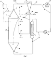
- the present invention insofar provides a reactor assembly for the production of polymers including a fluidized bed reactor (1) comprising a bottom zone (5), a middle zone (6) and an upper zone (7), one or more outlets (9) for fluidization gas streams (34) located in the upper zone (7), gas/solid separation means (2), a flow through device (29), a solid recycling line (35), a solid recycling inlet (37), a gas circulation line (38), an inlet (8) for fluidization gas located in the bottom zone (5) and an outlet for the polymer (14); the outlet (9) for the fluidization gas stream (34) being coupled with the fluidized bed reactor (1) via gas/solid separation means (2), gas circulation line (38) and inlet (8) and via solid recycling line (35), gas/solid separation means (2) and solid recycling inlet (37); the equivalent cross-sectional diameter of the bottom zone (5) being monotonically increasing with respect to the flow direction of the fluidization gas through the fluidized bed reactor (1); the equivalent cross-sectional diameter of the upper zone (7) being monotonically decreasing with respect to the flow
- the present invention further is directed to a method for polymerizing olefins in a fluidized bed reactor (1), wherein the fluidized bed is formed by polymer particles in an upwards rising fluidization gas said upwards rising fluidization gas has a superficial velocity in the middle zone (6) of from 0.05 to 0.8 m/s, said method comprising the steps of:
- the fluidized bed reactor is part of the reactor assembly according to the present invention.
- the reactor assembly preferably further comprises a controller (31).
- Fluidized bed reactors are well known in the prior art.
- the fluidization gas is passed through the fluidized bed within a certain superficial velocity.
- the superficial velocity of the fluidization gas must be higher than the fluidization velocity of the particles contained in the fluidized bed as otherwise no fluidization would occur.
- the superficial velocity should be substantially lower than the onset velocity of pneumatic transport, as otherwise the whole bed would be entrained with the fluidization gas.
- Reactors operating in transport regime exist. Such operation is commonly referred to as fast fluidization or fast fluidized beds.
- An overview is given, for instance, in Perry's, pages 17-1 to 17-12, or M Pell, Gas Fluidization (Elsevier, 1990), pages 1 to 18 and in Geldart, Gas Fluidization Technology, J Wiley & Sons Ltd, 1986 .
- Solids and fines according to the present invention are both particles.
- solids and fines according to the present invention are polymer particles.
- the term solids as used in the present application comprises the fines.
- fines are defined as solids having a mean particle size and/or particle size distribution (PSD) of less than a defined threshold value, i.e, below that threshold value solids are considered as fines.
- PSD mean particle size and/or particle size distribution
- d p particle size of less than 100 ⁇ m, preferably, less than 80 ⁇ m, more preferably less than 50 ⁇ m are defined as fines.
- Particle size distribution may be characterized,by indicating, both, the median particle size and the span of the particle size distribution.
- the span is usually defined as (d p,90- d p,10 )/d p,50 , where d p,90 is the particle size for which 90 % by the weight of the particles have a diameter which is smaller than d p,90 ; d p,10 is the particle size for which 10 % by the weight of the particles have a diameter which is smaller than d p,10 ; and d p,50 is the median particle size for which 50 % by the weight of the particles have a diameter which is smaller than d p,50 .
- the gas/solid separation means (2) allow separation of gas and solids.
- this can be a vessel where the solids, particularly polymer particles settle by gravity.
- the means for gas/solids separation comprise at least one gas/solid sepratation unit which is preferably a cyclone.
- a cyclone in its simplest form is a container in which a rotating flow is established. Cyclone design is well described in the literature. Particularly suitable cyclones are described in documents Kirk-Othmer, Encyclopaedia of Chemical Technology, 2nd edition (1966), Volume 10, pages 340-342 .
- the gas/solid separation means usually contains four gas/solid sepratation units or less.
- the solid filter means (41) also separates solids from gas.
- the solid filter means is optionally present in the reactor assembly according to the present invention in addition to the gas/solid separation means. Typically solid filter means are knock-out drums.
- the solid filter means are not comprised in the term gas/solid separation means. Accorindingly, restriction of the present invention to only one gas/solid separation unit in the gas/solid separation means does not exclude the additional presence of the solid filter means (41) in the reactor assembly.
- the flow through device (29) allows for varying the amount of a stream of particles, gas or fluid or mixtures thereof flowing through the device. The variation occurs by adjusting the flow through device. Thereby the flow through device lets pass 0 to 100 % of a stream in a certain direction. Furthermore, the flow through device may additionally allow for passing the rest 100 to 0 % of the stream in at least one additional direction. Furthermore, the flow through device (29) is preferably capable of sending and/or receiving signals to/from the controller (31).
- the flow through device comprises a valve.
- the valve can be a one-way valve or a multiport valve.
- Various valve designs are well known in the art.
- a controller (31) is any kind of device allowing for receiving and processing data and receiving and sending signals. Usually the controller is a computer.
- the fluidization gas stream of the present invention comprises fluidization gas and and may also comprise different amounts of solids. Accordingly, the word "gas” does not necessarily exclude that further components beside fluidization gas may be comprised in the fluidization gas stream.
- the amount and nature of solids comprised in the fluidization gas stream (34) and the gas circulation line varies and depends, among others, on where the content of solids is measured in the reactor assembly, as additional process steps are effected on the stream, the operating conditions of the fluidized bed reactor and the nature (e.g. density) of the polymer produced in the reactor. For instance, in the fluidization gas stream (34) in outlet line (33) more solids are contained than in the fluidization gas stream in gas circulation line (38), at the exit of the gas/solid separation means.
- Means for cooling (3) are required in view of the exothermic nature of the polymerization reactions.
- the means for cooling will be in the form of a heat exchanger.
- Means for pressurizing (4) enable the adjustment of the fluidization gas velocity. They are typically compressors.
- the fluidized bed reactor comprises a bottom zone (5), a middle zone (6) and an upper zone (7). These zones form the actual reaction zone denoting the room within the fluidized bed reactor designated for the polymerization reaction.
- the polymerization reaction will go on as long as the catalyst remains active and there is monomer to polymerize. Thus chain growths can also occur outside the actual reaction zone. For example, polymer collected in a collection vessel will still polymerize further.
- bottom -, middle - and upper zone indicate the relative position with respect to the base of the fluidized bed reactor.
- the fluidized bed reactor vertically extends in upward direction from the base, whereby the cross-section(s) of the fluidized bed reactor are essentially parallel to the base.
- the height of the fluidized bed reactor is the vertical distance between two planes with the lower plane crossing the lowest point of the bottom zone and the upper plane crossing the highest point of the upper zone.
- the vertical distance denotes the distance along a geometrical axis forming a 90° angle with the base and also the two planes, i.e. a gas entry zone (if present) shall as a matter of definition contribute to the height of the fluidized bed reactor.
- the height of the individual zones is the vertical distance between the planes limiting the zones.
- cross-section denotes the area of the intersection with a plane being parallel to the base. If not mentioned otherwise, the term cross-section always concerns the inner cross-section without internals. For example if the middle zone is cylindrical having an outer diameter of 4.04 m and the wall of the cylinder has a thickness of 0.02 m, the inner diameter will be 4.00 m, whereby the cross-section will be 2. 0 x 2. 0 x ⁇ m 2 ⁇ 12.6 m 2 .
- free cross-section denotes the area of the total cross-section allowing interchange of gases and particles.
- the free cross-section is the area, which is unobstructed.
- Monotonically decreasing is to be understood in a mathematical sense, i.e. the average diameter will decrease or will be constant with respect to the flow direction of the fluidization gas through the fluidized bed reactor.
- Monotonically decreasing equivalent cross-sectional diameter includes two situations namely the decrease of the equivalent cross-sectional diameter with respect to the flow direction of the fluidization gas through the fluidized bed reactor and also constancy of the equivalent cross-sectional diameter with respect to the flow direction of the fluidization gas. It should be understood, however, that even though a zone having a monotonically decreasing diameter in the direction of flow may have sections having an essentially constant diameter, the diameter at the downstream end of the zone is always smaller than the diameter at the upstream end of the zone.
- Equivalent cross-sectional diameter is the normal diameter in case of circular cross-section. If the cross-section is not circular, the equivalent cross-sectional diameter is the diameter of a circle having the same area as the cross-section of the non-circular cross-section embodiment.
- the three reaction zones, bottom zone, middle zone and upper zone shall differentiate as to their equivalent cross-sectional diameter.
- the boundary plane delimiting bottom zone and middle zone shall be the plane, where the cross-sectional diameter changes from increasing values to essentially constant values.
- the boundary plane delimiting middle zone and upper zone shall be the plane, where the cross-sectional diameter changes from essentially constant values to decreasing values.
- diameter is also used in the meaning of "equivalent cross-sectional diameter" for non-circular surfaces.
- Cone geometry plays an important role for the present invention.
- a cone is a three-dimensional geometric shape that tapers smoothly from a flat to the apex. This flat usually will be a circle but may also be elliptic. All cones also have an axis which is the straight line passing through the apex, about which the lateral surface has a rotational symmetry.
- the fluidized bed reactor includes a gas entry section, a first domain, wherein the superficial gas velocity of the fluidization gas is essentially constant, and a second domain being located above the first domain, wherein the superficial gas velocity of the fluidization gas is higher relative to the first domain, an inlet for the fluidization gas located in the gas entry section, an outlet for the fluidization gas located in the second domain; the outlet for the fluidization gas being coupled with the fluidized bed reactor via a gas circulation line; and means for separation of solids from gas being connected to said gas circulation line.
- Gas entry section denotes the part of the whole apparatus, where the feed takes place and the bed is formed.
- the gas entry section insofar differentiates from the so called first domain and second domain.
- the first domain denotes the part of the fluidized bed reactor, where the superficial gas velocity of the fluidization gas is essentially constant.
- the second domain is located vertically above the first domain and denotes the part of the fluidized bed reactor, where the superficial gas velocity of the fluidization gas is higher than in the superficial gas velocity in the first domain.
- Gas velocity shall mean the superficial gas velocity.
- the new reactor assembly has various advantages.
- the reactor can be operated so that the bed occupies almost the total volume of the reactor. This enables higher output / reactor size ratios further leading to substantial cost reduction.
- the polymer is evenly distributed within the reactor over the bed area and is accompanied by better coalescence of gas bubbles.
- the solids flow vicinal to the walls of the reactor is high which leads to a constant cleaning of the walls particularly in the upper zone.
- it has been surprisingly found that within the reactor assembly the entrainment of fines with the fluidization gas is reduced as the undesirably large bubbles are destroyed. Further, the heat removal from the polymer as a function of bed height is more even and there is a better dispersion between the gas and the polymer as in the prior art reactors and processes.
- a further important advantage of the present invention is that the separation of the polymer from the fluidization gas, for instance by using one or more cyclone(s), can easily be done due to a high concentration of solids in the fluidization gas. It has been surprisingly found that the solids content in the fluidization gas after the gas/solid separation is much lower in the present invention compared with a plant/process resulting in a feed to the gas/solids separation means characterized by a lower amount of solids. In other words, the relatively high amount of solids before the gas/solid separation in the present invention surprisingly results to a better degree of separation of solids.
- a further important advantage of the present invention is that the separation of the polymer from the fluidization gas, for instance by using one or more cyclone(s), can easily be done since the weight fraction of fines contained in the solids is reduced.
- fines are solids of a size below defined threshold. The fines have a very small mass due to their small size.
- the efficiency of the gas/solid separation means increases with the mass of particles to be separated from the gas.
- a cyclone acts by taking advantage of centrifugal forces its efficiency increases with the mass of particles to be separated from the gas. It has been surprisingly found that the amount of fines is low produced in the fluidized bed reactor according to the present invention.
- PSD narrow particle size distribution
- the mean particle size is simultaneously increased associated with an increasing mean mass of the particles. It has been surprisingly found that the recycling of solids, especially fines back to the fluidized bed reactor the mean particle size is enlarged.
- the fluidized bed reactor and the gas/solid separation means e.g. one or more cyclone(s) contribute to the solution in a synergistic way.
- the reactor assembly according to the present invention comprises an inlet for the catalyst or catalyst containing prepolymer.
- the catalyst or catalyst containing prepolymer may be fed via the inlet for the fluidization gas.
- a separate inlet for the catalyst or catalyst containing prepolymer allows good mixing of the catalyst into the bed.
- the catalyst is fed to the most turbulent zone.
- the reactor assembly according to the present invention preferably comprises an outlet for the removal of sheets, chunks and lumps. Though the formation rate for sheets, chunks and lumps is extremely low, it is not possible to suppress the formation thereof to zero under all reaction conditions. If present the outlet for the removal of sheets, chunks and lumps will be preferably located in the lowest part of the bottom zone. In the most preferred embodiment, the outlet will be positioned in the centre of the bottom zone. When the bottom zone has conical shape, the outlet will preferably fall together with the apex of the cone.
- the outlet for the removal of sheets, chunks and lumps is accompanied by means for the break-up of sheets, chunks and/or lumps.
- means for break-up of sheets, chunks and/or lumps are commercially available and they are discussed, among others, in Stolhandske, Powder and Bulk Engineering, July 1997 issue on pages 49 - 57 and Feldman, Powder and Bulk Engineering, June 1987 issue on pages 26 - 29 .
- the fluidized bed reactor according to the present invention comprises three zones, a bottom zone (5), a middle zone (6) and an upper zone (7).
- the fluidized bed reactor according to the present invention consists of three zones, a bottom zone (5), a middle zone (6) and an upper zone (7).
- the fluidized bed reactor according of the present invention comprises more than three zones, a bottom zone (5), a middle zone (6) and an upper zone (7) and at least one additional zone, whereby this at least one additional zone is located below the bottom zone (5) with respect to the flow direction of the fluidization gas.
- the equivalent cross-sectional diameter of the upper zone preferably is strictly monotonically decreasing with respect to the flow direction of the fluidization gas, i.e. generally in upwards vertical direction.
- the middle zone of the fluidized bed reactor typically will be in the form of a circular cylinder being denoted herein simply cylinder. However, it is possible that the middle zone of the fluidized bed reactor is in the form of an elliptic cylinder. Then the bottom zone preferably is preferably in the form an oblique cone. Then more preferably the upper zone is also in the form of an oblique cone.
- the middle zone will essentially form the first domain wherein the superficial gas velocity of the fluidization gas is essentially constant.
- the upper zone will essentially form the second domain wherein the superficial gas velocity of the fluidization gas is higher relative to the first domain.
- the upper zone of the reactor assembly according to the present invention is preferably shaped such that a gas-particle stream vicinal to the inner walls is created, whereby the gas-particle stream is directed downwards to the base.
- This gas-particle stream leads to an excellent particle-gas distribution and to an excellent heat balance. Further the high velocity of the gas and particles vicinal to the inner walls minimizes lump- and sheet formation.
- the ratio of the height of the upper zone to the diameter of the middle zone is within the range of from 0.3 to 1.5, more preferably 0.5 to 1.2 and most preferably 0.7 to 1.1.
- the reactor assembly according to the present invention includes an upper zone being cone-shaped and a middle zone being cylindrical shaped.
- the cone forming the upper zone preferably is a right circular cone and the cylinder forming the middle zone preferably is a circular cylinder.
- the cone-angle of the cone-shaped upper zone is 10° to 50°, most preferably 20 to 40°. As defined above, the cone-angle is the angle between the axis of the cone and the lateral area ( Fig. 3 ).
- the specific cone-angles of the cone-shaped upper zone further improve the tendency for back-flow of the particles countercurrent to the fluidization gas.
- the resulting unique pressure balance leads to an intensive break up of bubbles, whereby the space-time-yield is further improved.
- the wall flow velocity i.e., the velocity of particles and gas vicinal to the inner walls is high enough to avoid the formation of lumps and sheets.
- the reactor assembly according to the present invention preferably has a bottom zone shaped such that the particles distribute the gas over the whole cross-section of the bed.
- the particles act as a gas distribution grid.
- gas and solids are mixed in highly turbulent conditions. Because of the shape of the zone, the gas velocity gradually decreases within said bottom zone and the conditions change so that a fluidized bed is formed.
- reactor geometries can be combined with the aforementioned first embodiment consisting of three zones a bottom zone (5), a middle zone (6) and an upper zone (7) and the second embodiment including at least one additional zone, whereby this zone or these zones is/are located below the bottom zone.
- the equivalent cross-sectional diameter of the bottom zone is strictly monotonically increasing with respect to the flow direction of the fluidization gas through the reactor, i.e. generally vertically upwards.
- the bottom zone is cone-shaped and the middle zone is cylindrical shaped.
- the bottom zone preferentially has right circular cone shape and the middle zone is in the form of a circular cylinder.
- the middle zone is in the form of an elliptic cylinder and the bottom and the upper zone are in the form oblique cones.
- the cone-angle of the cone-shaped bottom zone is 5° to 30°, even more preferably 7° to 25° and most preferably 9° to 18°, whereby the cone-angle is the angle between the axis of the cone and the lateral surface ( Fig. 2 ).
- the equivalent diameter of the bottom zone increases from about 0.1 to about 1 metres per one metre of height of the bottom zone (m/m). More preferably, the diameter increase from 0.15 to 0.8 m/m and in particular from 0.2 to 0.6 m/m.
- the preferred cone-angles lead to additional improved fluidization behaviour and avoid the formation of stagnant zones.
- the polymer quality and stability of the process are improved.
- a too wide cone-angle leads to an uneven fluidization and poor distribution of the gas within the bed. While an extremely narrow angle has no detrimental effect on the fluidization behaviour it anyway leads to a higher bottom zone than necessary and is thus not economically feasible.
- an at least one additional zone being located below the bottom zone. It is preferred that the at least one additional zone, or if there is more than one additional zone, the total of the additional zones contributes/contribute to a maximum of 15 % to the total height of the reactor, more preferably 10 % to the total height of the reactor and most preferably less than 5 % of the total height of the reactor.
- a typical example for an additional zone is a gas entry zone.
- An unobstructed passageway in the direction of flow of the fluidization gas through the fluidized bed reactor between the bottom zone (5) and the upper zone (7).
- An unobstructed passageway includes all geometries which allow substantially free exchange of gas and particles between and within said zones.
- An unobstructed passageway is characterized by the absence of internals such as distribution plates and/or grids resulting in substantially increased flow resistivity. Accordingly, the fluidized bed reactor (1) of the present invention comprises no gas distribution grid and/or plates.
- An unobstructed passageway is characterized by a ratio of the free cross-section / total cross-section with respect to the partition between the bottom zone and the middle zone of at least 0.95, whereby the free cross-section is the area allowing interchange of gases and whereby the total cross-section is the area of the inner reactor cross section limited by the walls of the fluidized bed reactor.
- the middle zone has cylindrical form with an inner diameter of 4 meter
- the total cross-section is about 2.0 ⁇ 2.0 ⁇ m 2 ⁇ 12.6 m 2 .
- the area of the free cross-section i.e. the area allowing interchange of gases is at least 12.0 m 2 the criteria for an unobstructed passageway will be fulfilled.
- a typical example for an internal leading to a small reduction as to the cross-section allowing interchange of gases and solids is a vertical pipe.
- Such a pipe or a plurality of pipes directs flow and insofar has guiding function.
- the wall thickness of the pipe (and fasteners) only limit the cross-section to a very small degree, the interchange of gases and solids will be essentially not limited.
- the fluidized bed reactor assembly according to the present invention can be used for producing polymers in a commercial scale, for instance with a production capacity of from 2 to 40 tons per hour or 10 to 30 tons per hour.
- the reactor assembly according to the present invention preferably includes means for injection of the fluidization gas with an injection angle within the range of 120° to 150° with respect to the vertical axis of the fluidized bed reactor.
- the vertical axis forms a 90° angle with the base.
- the means for injection of the fluidization gas enable an injection angle in the range of 130° to 140°.
- the reactor assembly according to the present invention comprises an outlet for the polymer.
- the polymer can be withdrawn via the fluidization gas stream and the gas/solid separation means, e.g. the one or more cyclone(s).
- the outlet for the polymer preferably is located in the middle zone. More preferably the outlet is in the form of a nozzle. Typically there will be numerous nozzles located in the middle zone.
- At least a part of the polymer is withdrawn directly from the fluidized bed, meaning that the outlet nozzle withdraws polymer from a level which is above the base of the fluidized bed but below the upper level of the fluidized bed.
- the outlet nozzles for withdrawing polymer are located in the middle zone of the reactor. It is preferred to withdraw the polymer continuously, as described in WO 00/29452 . It is then also possible to withdraw a part of the polymer via the fluidization gas stream and the gas/solid separation means, e.g. the one or more cyclone(s).
- the polymer obtained directly from the fluidized bed and the polymer obtained via the fluidization gas stream and the gas/solid separation means are then usually combined.
- the circulation gas is cooled in order to remove the heat of polymerization. Typically, this is done in a heat exchanger.
- the gas is cooled to a temperature which is lower than that of the bed to prevent the bed from heating because of the reaction. It is possible to cool the gas to a temperature where a part of it condenses.
- the liquid droplets enter the reaction zone they are vaporised.
- the vaporisation heat then contributes to the removal of the reaction heat.
- This kind of operation is called condensed mode and variations of it are disclosed, among others, in WO-A-2007/025640 , US-A-4543399 , EP-A-699213 and WO-A-94/25495 .
- condensing agents are non-polymerizable components, such as n-pentane, isopentane, n-butane or isobutane, which are at least partially condensed in the cooler.
- the superficial gas velocity in the middle zone of the reactor is suitably within a range of from 5 to 80 cm/s (or, from 0.05 to 0.8 m/s), preferably from 0.07 to 0.7 m/s, such as 0.1 to 0.5 m/s or or 0.3 m/s or 0.2 m/s or 0.1 m/s.
- the reactor may be used for polymerizing monomers in the presence of a polymerization catalyst.
- Monomers which can thus be polymerized include olefins, diolefins and other polyenes.
- the reactor may thus be used to polymerize ethylene, propylene, 1-butene, 1-pentene, 1-hexene, 4-methyl-1-pentene, 1-heptene, 1-octene, 1-decene, styrene, norbornene, vinyl norbornene, vinylcyclohexane, butadiene, 1,4-hexadiene, 4-methyl-1,7-octadiene, 1,9-decadiene and their mixtures.
- the reactor is useful in polymerizing ethylene and propylene and their mixtures, optionally together with other alphaolefin comonomers having from 4 to 12 carbon atoms.
- Any polymerization catalyst may be used to initiate and maintain the polymerization.
- Such catalysts are well known in the art. Especially the catalyst should be in the form of a particulate solid on which the polymerization takes place.
- Suitable catalysts for olefin polymerization are, for instance, Ziegler-Natta catalysts, chromium catalysts, metallocene catalysts and late transition metal catalysts. Also different combinations of two or more such catalysts, often referred to as dual site catalysts, may be used.
- Suitable Ziegler-Natta catalysts and components used in such catalysts are given, for instance, in WO-A-87/07620 , WO-A-92/21705 , WO-A-93/11165 , WO-A-93/11166 , WO-A-93/19100 , WO-A-97/36939 , WO-A-98/12234 , WO-A-99/33842 , WO-A-03/000756 , WO-A-03/000757 , WO-A-03/000754 , WO-A-03/000755 , WO-A-2004/029112 , WO-A-92/19659 , WO-A-92/19653 , WO-A-92/19658 , US-A-4382019 , US-A-4435550 , US-A-4465782 , US-A-4473660 , US-A-4560671 , US-A-5539067
- Suitable metallocene catalysts are shown in WO-A-95/12622 , WO-A-96/32423 , WO-A-97/28170 , WO-A-98/32776 , WO-A-99/61489 , WO-A-03/010208 , WO-A-03/051934 , WO-A-03/051514 , WO-A-2004/085499 , EP-A-1752462 , EP-A-1739103 , EP-A-629631 , EP-A-629632 , WO-A-00/26266 , WO-A-02/002576 , WO-A-02/002575 , WO-A-99/12943 , WO-A-98/40331 , EP-A-776913 , EP-A-1074557 and WO-A-99/42497 ,
- the catalysts are typically used with different activators.
- activators are generally organic aluminium or boron compounds, typically aluminium trialkyls, alkylaluminium halides, alumoxanes
- modifiers such as ethers, alkoxysilanes, and esters and like may be used.
- different coreactants may be used. They include chain transfer agents, such as hydrogen and polymerization inhibitors, such as carbon monoxide or water.
- an inert component is suitably used. Such inert component may be, for instance, nitrogen or an alkane having from 1 to 10 carbon atoms, such as methane, ethane, propane, n-butane, isobutane, n-pentane, isopentane, n-hexane or like. Also mixtures of different inert gases may be used.
- the polymerization is conducted at a temperature and pressure where the fluidization gas essentially remains in vapour or gas phase.
- the temperature is suitably within the range of from 30 to 110 °C, preferably from 50 to 100 °C.
- the pressure is suitably within the range of from 1 to 50 bar, preferably from 5 to 35 bar.
- the reactor is preferably operated in such conditions that the bed occupies at least 70 % of the combined volume of the middle zone and the upper zone, more preferably at least 75 % and most preferably at least 80 %.
- the reactor is operated in this manner it has been found that surprisingly the bubbles break up at the upper part of the reactor or are prevented from growing. This is advantageous for a number of reasons. First, when the volume occupied by the bubbles is reduced, the volume of the reactor is more effectively used for the polymerization and the "dead" volume is reduced. Second, the absence of large bubbles reduces the entrainment of fines from the reactor.
- the polymer that is carried out of the reactor with the fluidization gas represents the total polymer within the reactor. Therefore, it is possible to separate the polymer from the fluidization gas, for instance by using a cyclone, and withdraw this polymer as the product or direct it into further polymerization stages. In addition to that, the separated solids can be recycled back to the fludized be reactor. Third, even though polymer particles are entrained from the reactor together with the fluidization gas, the polymer is surprisingly easier to separate from the fluidization gas than if the amount of polymer were smaller. Fourth, the polymer particles obtained from the reactor with the fluidization gas surprisingly contain a minimized fraction of fines.
- the reactor assemblies and the processes according to the present invention combine a fluidized bed reactor and means for separation of solids/gas in a synergistic way. Furthermore, the underflow stream has better flow properties and is less prone for plugging than in a similar conventional process.
- the fluidization gas is withdrawn from the upper zone of the fluidized bed reactor.
- one or more outlets are provided in the upper zone, more preferably, these one or more outlets are located at a height of more than 90 % of the total height of the fluidized bed reactor.
- the one or more outlets are preferably located in the upper zone all at the same height or all at different heights or a combination of both on the fluidized bed reactor.
- At least one of the one or more outlets is/are located at a height of more than 95 % of the total height of the fluidized bed reactor.
- one outlet is located at the highest port of the reactor and the other outlets, if present, are located at a height of more than 90 % of the total height of the fluidized bed reactor, even more preferably one outlet is located at the highest port of the reactor and the other outlets, if present, are located at a height of more than 95 % of the total height of the fluidized bed reactor and most preferably, only one outlet for withdrawal of fluidization gas is present in the upper zone of the fluidized bed reactor and is located at the highest port of the reactor.
- the one or more outlets are connected to one or more outlet lines.
- the outlet lines convey the fluidization gas stream to the gas/solid separation means comprising one or more gas/solid separation units.
- the number of outlets can, but need not equal the number of gas/solid separation units. For instance, when some or all of the more outlet lines are merged fluidization gas from a certain number of outlets can be conveyed to a minor number of gas/solid separation unit. Preferably, only one gas/solid separation unit is present in the gas/solid separation means.
- the one or more gas/solid separation units are one or more cyclones. More preferably only one cyclone is present in the gas/solid separation means.
- the one or more outlets in the upper zone of the reactor are connected to one or more outlet lines.
- the outlet lines convey the fluidization gas stream (34) to the gas/solid separation means comprising one or more gas/solid separation units.
- the entirety of streams conveyed through the one or more outlet lines is the fluidization gas stream (34).
- the overhead stream contains less solids by weight than the solid recycling stream.
- the overhead stream contains less than 5.0 % by weight, more preferably less than 3.0 % and even more preferably less than 1.0 % by weight, even more preferably less than 0.75 % and most preferably less than 0.5 % by weight of solids.
- the gas amount in the overhead stream is more than 95.0 %, more preferably more than 97.0 %, even more preferably more than 99.0 % even more preferably more than 99.25 % and most preferably more than 99.5 % by weight.
- the solid recycling stream (36) typically contains mainly solid material and includes some gas between the particles. Accordingly the solid recycling stream contains the majority of the mass of the polymer particles that were entrained from the fluidized bed reactor with the fluidization gas stream (34) Typically the solid recycling stream (36) contains at least 75 %, preferably 80 % and more preferably 85 % by weight solids and only at most 25 %, preferbly 20 % and most preferably 15 % by weight gas.
- the gas/solid separation means may comprise one or more gas/solid separation units.
- gas/solid separation means contain only one gas/solid separation unit the unit overhead stream is identical to the overhead stream and the unit solid recycling stream is identical to the solid recycling stream.
- the gas/solid separation unit being a cyclone the unit overhead stream is taken from the top outlet of the cyclone and the unit solid recycling stream, is the underflow of the cyclone taken from the bottom outlet of the cyclone.
- these gas/solid separation units may be either arranged in parallel or series.
- the unit overhead stream of each gas/solid separation unit contains less than 5.0 % by weight, more preferably less than 3.0 % and even more preferably less than 1.0 % by weight, even more preferably less than 0.75 % and most preferably less than 0.5 % by weight of solids.
- the gas amount in the unit overhead stream of each gas/solid separation unit is more than 95.0 %, more preferably more than 97.0 %, even more preferably more than 99.0 % even more preferably more than 99.25 % and most preferably more than 99.5 % by weight.
- the unit solid recycling stream contains mainly solid material and includes some gas between the particles. Accordingly the unit solid recycling stream contains the majority of the mass of the polymer particles that were entrained from the fluidized bed reactor with the fluidization gas stream (34) Typically the unit solid recycling stream contains at least 75 %, preferably 80 % and more preferably 85 % by weight solids and only at most 25 %, preferbly 20 % and most preferably 15 % by weight gas.
- the one or more outlets in the upper zone of the reactor are connected to one or more outlet lines.
- the outlet lines convey the fluidization gas stream (34) to the gas/solid separation means comprising one or more gas/solid separation units.
- the fluidization gas stream (34) is split and a portion thereof is fed to each gas/solid separation unit.
- portion denotes a part of the whole which does not differ in its physical properties from another portion.
- preferably only one outlet line for conveying the fluidization gas stream (34) is present.
- the gas/solid separation units are arranged in parallel preferably only one outlet line which conveys the fluidization gas stream (34) to the gas/solid separation means as mentioned in the foregoing paragraph is present and the fluidization gas stream (34) is split and a portion thereof is fed to each gas/solid separation unit.
- splitting or combination and subsequent splitting of the streams in the outlet line(s) such that the gas/solid separation is effected in more than one gas/solid separation unit allows the usage of smaller gas/solid separation units. Furthermore, in case one gas/solid separation unit fails it is not necessary to completely stop the process but replacement of gas/solid separation unit during operation is possible.
- valves are present in each outlet line.
- each of said outlet lines maybe connected to a different gas/solid separation unit.
- the stream in each outlet line is further split into two or more streams and each individual stream is fed to a different gas/solid separation unit or in case more than two outlet lines are present instead of being further split, the streams of two outlet lines may also be combined and fed to a gas/solid separation unit.
- the unit overhad streams of all gas/solid separation units are combined prior to further treatment, e.g. in the solid filter means (41).
- the combination is the overhead stream (42) obtained from the gas/solid separation means.
- the unit solid recycling streams of all gas/solid separation units in case of a parallel arrangement of the gas/solid separation units are preferably combined prior to any further treatment such as introduction into the flow through device, as further described below.
- the unit solid recycling streams of the gas/solid separation units in case of a parallel arrangement of the gas/solid separation units may also be introduced into individual flow through devices and the streams obtained from each flow through device are combined.
- gas/solid separation units are connected in series.
- the unit overhead stream of each gas/solid separation unit contains less than 5.0 % by weight, more preferably less than 3.0 % and even more preferably less than 1.0 % by weight, even more preferably less than 0.75 % and most preferably less than 0.5 % by weight of solids.
- the gas amount in the unit overhead stream of each gas/solid separation unit is more than 95.0 %, more preferably more than 97.0 %, even more preferably more than 99.0 % even more preferably more than 99.25 % and most preferably more than 99.5 % by weight.
- the unit solid recycling stream contains mainly solid material and includes some gas between the particles. Accordingly the unit solid recycling stream contains the majority of the mass of the polymer particles that were entrained from the fluidized bed reactor with the fluidization gas stream (34) Typically the unit solid recycling stream contains at least 75 %, preferably 80 % and more preferably 85 % by weight solids and only at most 25 %, preferbly 20 % and most preferably 15 % by weight gas.
- the one or more outlets in the upper zone of the reactor are connected to one or more outlet lines.
- the outlet lines convey the fluidization gas stream (34) to the gas/solid separation means comprising one or more gas/solid separation units.
- the streams are combined to form the fluidization gas stream (34).
- the fluidization gas stream (34) is fed to a first gas/solid separation unit.
- This first unit overhead stream obtained from the first gas/solid separation unit is fed to a second gas/solid separation unit.
- the unit overhead stream of the second gas/solid separation unit is the overhead stream of the gas/solid separation means.
- the unit solid recycling streams obtained from the first and the second gas/solid separation units are preferably combined prior to any further treatment such as introduction into the flow through device, thereby forming the solid recycling stream obtained from the gas/solid separation means.
- any further treatment such as introduction into the flow through device, thereby forming the solid recycling stream obtained from the gas/solid separation means.
- the unit overhead stream of the third gas/solid separation unit is the overhead stream of the gas/solid separation means.
- the unit solid recycling streams obtained from the first, second and third gas/solid separation units are preferably combined prior to introduction into the flow through device, thereby forming the solid recycling stream obtained from the gas/solid separation means.
- the unit overhead stream obtained from the first gas/solid separation unit is subjected to further gas/solid separation steps.
- Such an arrangement may be used in case a high amount of fines is generated due to the nature of the polymer produced.
- the gas/solid separation means contain
- the unit overhead stream is identical to the overhead stream and the unit solid recycling stream is identical to the solid recycling stream.
- the gas/solid separation is conveniently performed by cyclones.
- the gas/solid separation units are preferably cyclones.
- the unit overhead stream is taken from the top outlet of the cyclone and the unit solid recycling stream , i.e. the underflow of the cyclone, is taken from the bottom outlet of the cyclone.
- a gas streamcontaining solids enters a cylindrical or conical chamber tangentially at one or more points.
- the gas leaves as unit overhead stream or, in case only one cyclone is present in the gas/solid separation means leaves as overhead stream (42) through a central opening at the top, top outlet , of the cyclone chamber and the solids as unit solid recycling stream (underflow) through an opening at the bottom, bottom outlet , of the cyclone chamber.
- the solids are forced by inertia towards the walls of the cyclone from where they fall downwards.
- the stream of solids from the bottom outlet of the cyclone is the unit solid recycling stream or, in case only one cyclone is present in the gas/solid separation means the solid recycling stream (36).
- the gas circulation line (38) runs from the top outlet of the gas/solid separation means (2) to the inlet for fluidization gas (8), thus, in the gas circulation line (38) further devices such as solid filter means (41), means for cooling (3), means for pressurizing (4) etc. may be present.
- the solid recycling stream is recycled via a solid recycling line, gas/solid separation means to the solid recycling inlet back to the fluidized bed reactor.
- the solid recycling line includes a flow through device.
- the flow through device (29) allows for varying the amount of a stream of particles, gas or fluid or mixtures thereof flowing through the device. The variation occurs by adjusting the flow through device. Thereby the flow through device lets pass 0 to 100 % of a stream in a certain direction. Furthermore, the flow through device may additionally allow for passing the rest 100 to 0 % of the stream in at least one additional direction.
- the flow through device (29) in the solid recycling line supplies 0 to 100 %, preferably 10 to 90 %, more preferably 10 to 60 % of the solid recycling stream (36) upstream of the flow through device to the fluidized bed reactor based on the volume of the solid recycling stream (36) upstream of the flow through device.
- the flow through device (29) may additionally allow for branching off from the solid recycling stream (36) entering the flow through device a stream to downstream process stages (40) directed to down stream process stages through the line to downstream process stages (39) . It is possible to branch off up to 100 % of the volume of the solid recycling stream (36) upstream of the flow through device to the stream to downstream process stages (40).
- the stream to downstream process stages (40) is 100 to 0 %, preferably 90 to 10 %, more preferably 90 to 40 % based on the volume of the solid recycling stream (36) upstream of the flow through device.
- the remaining solid recycling stream (36) downstream of the flow through device (29) corresponds to the difference of the solid recycling stream (36) upstream of the flow through device minus the stream to downstream process stages (40).
- the relation between the solid recycling stream downstream of the flow through device (29) and the at least one further stream is described by ratio of the flow rate of the solid recycling stream downstream of the flow through device (29) to the flow rate of the at least one further stream based on the volume of the streams.
- the control of the volume of the solid recycling stream downstream of the flow through device (29) with respect to the solid recycling stream upstream of the flow through device (29) may be effected by routing 100 % of the solid recycling stream upstream of the flow through device (29) to the fluidized bed reactor for a fraction of the total time of the polymerization process and the remaining time to other stream(s), e.g. the stream to downstream process stages (40).
- the fractions of time are usually chosen to obtain the above relations between the flow rate of the solid recycling stream downstream of the flow through device to the flow rate of the at least one further stream based on the volume of the streams.
- fractions of time and split are usually chosen to obtain the above relations between the flow rate of the solid recycling stream downstream of the flow through device to the flow rate of the at least one further stream based on the volume of the streams.
- the flow through device preferably comprises a valve.
- One alternative of a flow through device is a multiport valve.
- a multiport valve usually contains at least three connections and at least two settings.
- An example of a valve having on/off settings is a three-way ball valve of L-type.
- These two settings can also be 90/10 and 10/90, i.e. either 90 % of the volume of the solid recycling stream (36) upstream of the flow through device is routed to the fluidized bed reactor and 10 % of the volume of the solid recycling stream (36) upstream of the flow through device is routed to the stream to downstream process stages (40) or 10 % of the volume of the solid recycling stream (36) upstream of the flow through device is routed to the fluidized bed reactor and 90 % of the volume of the solid recycling stream (36) upstream of the flow through device is routed to the line to downstream process stages (39) to downstream process stages (40).
- Alternative setting may be 60/40 and 10/90 or 60/40 and 40/60.
- the multiport valve may also have more than two settings, e.g. 90/10; 60/40; 40/60 and 10/90.
- the multiport valve may allow for supplying a variable percentage of the volume of the solid recycling stream (36) upstream of the flow through device to the the fluidized bed reactor.
- the regulation of the volume of the solid recycling stream to the fluidized bed reactor is not stepwise but can be continous between 0 and 100 % with respect to the volume of the solid recycling stream upstream of the flow through device.
- Another alternative of the flow through device used in the present invention comprises a simple branch point having one inlet and at least two outlets, preferably the simple branch point is having one inlet and two outlets.
- the line to downstream process stages (39) is connected to one of the outlets of the simple branch point and a line L A is connected to a different outlet of the simple branch point, the line L A is connected to the inlet of a control valve and the outlet of the control valve is connected to the fluidized bed reactor.
- This stream downstream of the control valve ist the solid recycling stream (36) downstream of the flow through device.
- the solid recycling line (36) downstream of the flow through device is connected to one of the outlets of the simple branch point and a line L B is connected to a different outlet of the simple branch point, the line L B is connected to the inlet of a control valve and the outlet of the control valve is connected to the line to downstream process stages (39).
- the simple branch point may be replaced by a three-way ball valve of T-type which allows one inlet to be connected with either one or both of the outlets.
- the settings 0/100 and 100/0 can be effected directly at the branch.
- the flow through device is either a one-way valve or a multiport valve.
- the multiport valve contains at least three connections and at least two settings. The at least two settings are not absolute. The least two settings merge, thereby providing intermediate positions allowing the outflow of at least two solid recycling streams having the same or different amounts.
- the multiport valve is a 3/2-way valve.
- the flow through device allows for varying the amount of solid recycling stream flowing trough the device.Thereby the flow through device lets pass 0 to 100%, preferably 10 to 60%, of solid recycling stream to the fluidized bed reactor.
- the flow through device may additionally allow for routing the rest 100 to 0%, preferably 90 to 40% of solid recycling stream to down stream process stages.
- the gas stream may consist of inert gases, such as nitrogen or saturated hydrocarbons, such as ethane, propane, butanes, pentanes and the like. It may, however, also comprise or consist of the fluidization gas or comprise one or more components forming the fluidization gas together with one or more inert gases.
- inert gases such as nitrogen or saturated hydrocarbons, such as ethane, propane, butanes, pentanes and the like. It may, however, also comprise or consist of the fluidization gas or comprise one or more components forming the fluidization gas together with one or more inert gases.
- the adjusting of the flow through device occurs via a controller.
- downstream process stages are further process or reaction steps.
- downstream process stages comprise at least the steps of mixing the polymer with additives and extruding the polymer comprising the additives into pellets.
- They may also comprise a further reactor, means for cooling, means for pressurizing and/or one or more outlets for the polymer.
- a further reactor is a moving bed reactor allowing for a dual reactor assembly. Dual reactor assemblies in general are well-known in the art.
- the polymer stream withdrawn from the fluidized bed reactor (1) via outlet of the polymer (14) and the solid recycling stream branched off to the output of the polymer (40) downstream from the flow through device can be combined for product recovery.
- a controller (31) and the flow through device (29) preferably communicate with each other by sending and receiving one or more signals in at least one direction between the flow through device (29) and the controller (31).
- the one or more signal is only sent by the controller and received by the flow through device.
- the one or more signal is only sent by the flow through device and received by the controller.
- the one or more signal is digital, electric, mechanic, electromagnetic and/or a combination thereof. More preferably the signal is digital. Due to that communication the flow through device (29) is adjusted by the controller (31). As a consequence the flow though device (29) varies and/or routes the solid recycling stream (36) as outlined above.
- the controller (31) is a device that receives and/or sends signals to the flow through device as outlined above. Furthermore the controller is a device that can receive data, process the data and send signals to the fluidized bed reactor. Furthermore, preferably the controller is a device that communicates with the fluidized bed reactor. Preferably the controller is a computer.
- the received data are preferably in digital form. The received data originate in the measurement of the mean particle size and/or the particle size distribution of an fluidization gas stream (34) from the fluidized bed reactor and/ or originate in the analysis of the operation conditions in the fluidized bed reactor.
- the particle size d p may be and preferably is measured as follows.
- the particle size d p is measured using a Beckman Coulter LS 200 Laser Diffraction Particle Size Analyser.
- the samples were prepared by mixing the polymer powder with isopropyl alcohol to a paste, which is further mixed in an ultra sound bath for 20 - 30 seconds.
- the paste is added to the sample unit of the Coulter instrument which contains isopropyl alcohol.
- the recommended powder concentration is 8 to 12 %.
- the size of the sample unit is 125 ml.
- the analysis is performed according to the computer program of the software LS32, version 3.10.2002 of the instrument.
- the run length is 60 seconds.
- the calculation of the results is made by the software. Thereby the particle size distribution is obtained.
- the characteristics such as the median particle size, different average particle sizes, the variance, the standard deviation, and the span can be calculated.
- Mass flow rate of solids may be determined by any method known in the art. These include gravimetric methods and the methods based on Coriolis force.
- Weight fraction of solids may be also be determined by using any applicable method, such as by taking samples and separating and weighing the components; or, by determining the density of the stream (for instance, by using Coriolis or radioactive methods), analyzing the gas composition and then calculating the solids content from the measured density of the mixture, calculated density of the gas (calculated from the composition) and the known density of the polymer.
- the flow rates can be determined by any method known in the art, such as methods based on Coriolis force; methods based on thermal conductivity; methods based on pressure difference; and others.
- Suitable apparatuses for the measurement of the mass flow rate of solids flows are LB442 distributed by Berthold Technologies (radioactive) and Multicor distributed by Schenck AccuRate (Coriolis force).
- a suitable apparatus for the measurement of the flow rate is Micro Motion (e.g. Elite Coriolis meter) distributed by Emerson Process Management.
- the measurement of the gas composition is also well-known in the art and is usually accomplished by on-line gas chromatography.
- a suitable apparatus therefor is Maxum of Siemens.
- the solids content of the flow can be calculated from the densities of the gas which, in turn is calculated from the composition, density of the solid, i.e. the density of the polymer which is known and the density of the mixed stream which has been measured.
- Analysis of the operation conditions in the fluidized bed reactor preferably comprises analysis of the parameters concerning fluidization conditions. More preferably the analysis comprises the measurement of the contents of the components of the fluidization gas, such as the contents of monomer, hydrogen, comonomers and eventual inert components, the flow rate of the fluidization gas, the temperature and the pressure of the fluidization gas at various points of the gas circulation line, the temperature and pressure at various levels of the reactor and the contents of solids in the fluidization gas stream.
- the analysis comprises the measurement of the contents of the components of the fluidization gas, such as the contents of monomer, hydrogen, comonomers and eventual inert components, the flow rate of the fluidization gas, the temperature and the pressure of the fluidization gas at various points of the gas circulation line, the temperature and pressure at various levels of the reactor and the contents of solids in the fluidization gas stream.
- the controller ensures that the operation conditions in the fluidized bed reactor are maintained over the full production period.
- the controller and the fluidized bed reactor assembly preferably communicate with each other by sending and receiving one or more signals in at least one direction between the the fluidized bed reactor and the controller.
- the one or more signal is only sent by the controller and received by the fluidized bed reactor assembly.
- the one or more signal is only sent by the fluidized bed reactor assembly and received by controller.
- the one or more signal is digital, electric, pneumatic, electromagnetic and/or a combination thereof. More preferably the signal is digital.
- the actual particle cut diameter d 50 is determined and compared with a predetermined threshold value for the particle cut diameter (thres).
- the actual particle cut diameter, d 50 is the diameter of the particle that has a 50 % probability of being collected by the cyclone.
- the actual particle cut diameter d 50 can be determined experimentally by collecting solid samples over a given period of time both from the solid recycling stream (36) and the overhead stream (42). The particle size distribution is then determined from the solid samples. Furthermore, the solid concentration of the overhead stream (42) sample is determined. The flow rates of the fluidization gas stream (34) entering the cyclone and of the overhead stream (42) leaving the cyclone are measured as well as the flow rate of the solid recycling stream (36).
- the efficiency of the cyclone can then be evaluated by comparing the experimentally obtained acutal value of dso to a predetermined upper threshold (thres). If the experimental value dso is higher than the predertermined value (thres), then the efficiency is not at a desired level. Then the return flow of the solid recycling stream (36) into the fluidized bed reactor is increased. In case, a stream to downstream process stages is branched off from the solid recycling stream, the volume of the stream to downstream process stages is thereby concomitantly decreased. Accordingly, the ratio of the flow rate of the solid recycling stream to the flow rate of the stream to downstream process stages is increased based on the volume of the streams.
- the particle size analysis can be done off-line by sieving, or, preferably, by using a particle counter, such as those manufactured and sold by Beckman Coulter and Malvern.
- a particle counter such as those manufactured and sold by Beckman Coulter and Malvern.
- Such instruments can be used in-line, where a sample is directed automatically to the analyzer and measured. The data is then sent to the process controller or process computer. Instruments may also be used off-line, so that a sample is taken manually and then analyzed. The data is then manually entered into the process computer or controller.
- the efficiency of gas/solid separation in the gas/solid separation means is higher in case the mass fraction of solids in the fluidization gas stream entering the gas/solid separation means is higher.
- the efficiency of the gas/solid separation means is estimated by determining the amount of solids entering the gas/solid separation means. If the amount of solids in the fluidization gas stream entering the gas/solid separation meansis too low then the flow of polymer in the solids recycling stream is increased. This gradually increases the level of the fluidized bed in the reactor. This in turn increases the flow rate of polymer particles entrained by the fluidization gas, thereby increasing the efficiency of the gas/solid separation means. Furthermore, thereby the mass fraction of fines in the solids contained in the fluidization gas stream is reduced.
- the solid recycling stream (36) is increased when the content of fines, usually deduced from the measured particle size distribution of of an fluidization gas stream (34) from the fluidized bed reactor (1) is larger than a predetermined set point for the content of fines.
- the variation of the flow of the solid recycling stream back to the fluidized bed reactor is achieved by adjusting the flow through device as outlined above.
- the adjustment of the flow through device may be effected by a controller..
- the controller includes a model of the process and thus can predict some process variables. For instance, the controller predicts the mean particle size, span of the particle size distribution and/or the whole particle size distribution of the particles contained in the fluidization gas stream using the data obtained in analyzing the operation conditions in the fluidized bed reactor. As outlined above, these predicted values may then be compared to the measured mean particle size, span of particle size distribution and/or the particle size distribution. Further, also other process variables, such as the content of solids in the fluidization gas, both before and after the cyclone, may be predicted. The predicted values may then be adjusted so that they better fit with the measured values. Methods to do this are well known in control engineering and include, for instance, Extended Kalman Filter and Instrumental Variables.
- the solid recycling stream is increased when the content of fines according to the measurement of the particle size distribution is larger than the predetermined maximum level.
- the solid recycling stream may be increased if the solids content in the fludization gas stream is too low.
- these control actions may be based on measured or predicted values.
- the fluidization gas enters into the gas entry zone below the bottom zone of the fluidized fed reactor.
- the gas and eventual polymer or catalyst particles are mixed in turbulent conditions.
- the velocity of the fluidization gas is such that the eventual catalyst or polymer particles contained therein are transferred into the bottom zone.
- polymer agglomerates, such as lumps or sheets fall downwards and may be thus removed from the reactor.
- the gas entry zone is a pipe typically having a diameter such that the gas velocity is higher than about 1 m/s, such as from 2 to 70 m/s, preferably from 3 to 60 m/s. It is also possible that the gas entry zone has an increasing diameter in the flow direction so that the gas velocity at the upper part of the gas entry zone is lower than at the bottom part.
- the gas enters from the gas entry zone to the bottom zone.
- a gas entry zone as a matter of definition shall not be seen as part of the reactor and insofar shall not contribute to the height of the reactor.
- the gas velocity is gradually reduced so that at the top of the bottom zone the superficial gas velocity is from about 0.02 m/s to about 0.9 m/s, preferably from 0.05 to about 0.8 m/s and more preferably from about 0.07 to about 0.7 m/s, such as 0.5 m/s or 0.3 m/s or 0.2 m/s or 0.1 m/s,
- the superficial velocity of the fluidization gas monotonously decreases within the bottom zone, remains at a constant level within the middle zone and monotonously increases within the upper zone.
- the superficial velocity increases as described above.
- the middle zone of the fluidized bed reactor is maintained under conditions such that the superficial gas velocity is from 5 to 80 cm/s, preferably 10 to 70 cm/s.
- the polymerization catalyst can be fed directly or can originate from a previous prepolymerization stage, the later being preferred.
- the polymerization catalyst is preferably introduced into the middle zone via the respective inlet.
- the withdrawal of the reaction product is preferably continuous such as disclosed in WO-A-00/29452 .
- the reactor assembly according to the present invention further comprising a loop reactor upstream of said fluidized bed reactor.
- the methods according to the present invention are carried out in the reactor assembly according to the present invention including all preferred embodiments thereof.
- the uses of the reactor are carried out in the reactor assembly according to the present invention including all preferred embodiments thereof.
- a controller (31), a flow through device (29) and a solid recycling line (35) in a reactor assembly for the production of polymers for minimizing the amount of fines produced by a fluidized bed reactor (1), the reactor assembly including a fluidized bed reactor comprising a bottom zone (5), a middle zone (6) and an upper zone (7), one or more outlets (9) for fluidization gas streams (34) located in the upper zone (7), gas/solid separation means (2), a flow through device (29), a solid recycling line (35), a solid recycling inlet (37), a gas circulation line (38), an inlet (8) for fluidization gas located in the bottom zone (5) and a controller (31).
- the processes according to the present invention are carried out in the reactor assembly according to the present invention including all preferred embodiments thereof.
- the present invention relates to a process for the production of polymers in the presence of a polymerization catalyst in a reactor assembly including a fluidized bed reactor as described above.
- the processes according to the present invention preferably concern the polymerization of polyolefins. More preferably the polyolefins are momoners selected from the group of ethylene, propylene, and C 4 to C 12 alpha olefins.
- the reactor assembly according to the present invention comprises a fluidized bed reactor (1) having a bottom zone (5), a middle zone (6) and an upper zone (7),
- the bottom zone (5) and the middle zone (6) (and also the upper zone (7)) form an unobstructed passageway as there is no distribution plate.
- the equivalent cross-sectional diameter of the bottom zone (5) being monotonically increasing with respect to the flow direction of the fluidization gas through the fluidized bed reactor;
- the one or more outlets (9) in the upper zone (7) of fluidized bed reactor (1) are connected with one or more outlet lines (33) for conveying the fluidization gas stream (34) to gas/solid separation means (2).
- the gas/solids separation means (2) comprise two outlets, one top outlet (27) and one bottom outlet (28).
- the fluidization gas exits the top outlet (27) as overhead stream (42).
- the overhead stream (42) is conducted via gas circulation line (38) to the inlet (8) in the bottom zone (5) of the fluidized bed reactor (1) whereby a fluidization gas circuit is established.
- the gas circulation line (38) includes means for pressurizing (4) and means for cooling (3) of the gas.
- the gas circulation line (38) further includes solid filter means (41) for further reducing the amount of solids and especially fines still contained in the fluidization gas stream. These solid filter means (41) are located upstream from the means for preasurizing (4) and means for cooling (3).
- the solid recycling stream (36) mainly containing solids exits the gas/solids separation means (2) by the bottom outlet (28).
- the solid recycling stream (36) is conveyed via solid recycling line (35) to the solid recycling inlet (37) in the middle zone (6) of the fluidized bed reactor (1) whereby a solid circuit is established.
- the solid recycling line (35) includes a flow through device (29).
- the flow though device (29) varies the solid recycling stream (36), whereby the whole solid recycling stream (36) or only a part of it is delivered to the fluidized bed reactor (1).
- the flow through device (29) may be fully closed such that there is no recycling taking place.
- the flow through device (29) a stream to downstream process stages (40) can branched off from the solid recycling stream (36). Therefore, the flow through device (29) can also vary the stream to downstream process stages (40) and/or an outlet.
- the stream to downstream process stages (40) corresponds to the part of the solid recycling stream (36) not being delivered to the fluidized bed reactor (1).
- the mean particle size and/or the particle size distribution is measured.
- the operation condition inside the fluidized bed reactor (1) are analyzed. Analysis typically includes the measurement of the fluidization velocity, u f , and/or comonomer concentration, C c .
- the obtained data (30) regarding particle size and operation condition are sent to a controller (31).
- the data (30) are processed by a controller (31).
- the controller (31) and the flow through device (29) communicate with each other by sending one or more signals in at least one direction between the flow through device (29) and the controller (31). Due to that communication the flow through device (29) is adjusted by the controller (31), whereby the flow though device (29) varies in the following at least the solid recycling stream (36) back to the fluidized bed reactor (1) as outlined above.
- the reactor assembly according to figure 4 is a modification of the reactor assembly according to figure 1 .
- the gas/solid separation means (2) shown by the dotted rectangle contain a first gas/solid separation unit (43) and a second gas/solid separation unit (44).
- the first gas/solid separation unit (43) has a top outlet (48) for the unit overhead stream of first gas/solid separation unit (47).
- the unit overhead stream of first gas/solid separation unit (47) is fed to the second gas/solid separation unit (44).
- the unit overhead stream of the second gas/solid sepration unit obtained through outlet (27) is the overhead stream (42).
- the unit solid recycling streams (46) obtained through outlets (45) are combined. These combined streams are the solid recycling stream (36) obtained in solid recycling line (35).
- the invention was exemplified with a reactor made of steel having the following dimensions: Height of the bottom zone: 1680 mm Diameter at the bottom of the bottom zone: 175 mm Height of the middle zone: 2050 mm Height of the upper zone: 670 mm Diameter of the middle zone: 770 mm
- the reactor described above was used for copolymerization of ethylene and 1-butene at a temperature of 80 °C and a pressure of 20 bar.
- the height of the fluidized bed, calculated from the bottom of the middle zone was 2100 mm.
- Ethylene, hydrogen and 1-butene were continuously introduced into the circulation gas line so that the ethylene concentration in the fluidization gas was 17 % by mole, the ratio of 1-butene to ethylene was 100 mol/kmol and the ratio of hydrogen to ethylene was 15 mol/kmol.
- the reminder of the fluidization gas was nitrogen.
- the flow rate of the gas was adjusted so that the superficial gas velocity in the middle zone of the reactor was 15 cm/s.
- the resulting copolymer could be easily withdrawn via an outlet at a rate of 68 kg/h.
- the fluidization gas flow was thus 250 m 3 /h, corresponding to a mass flow rate of 4800 kg/h.
- the polymer content in the fluidization gas stream withdrawn from the top of the fluidized bed reactor was about 0.25 % by weight and thus 12.0 kg/h of polymer was withdrawn together with the fluidization gas.
- the fluidization gas stream was passed through a cyclone where 11.4 kg/h of the polymer was recovered from the cyclone as a bottom stream while 0.6 kg/h remained with the fluidization gas stream.
- the entire bottom stream from the cyclone was combined with the product stream withdrawn from the reactor and directed to product recovery where it was mixed with additives and extruded to pellets.
- the solid recycling stream branched off to the output of the polymer downstream from the flow through device was combined for product recovery with the polymer stream withdrawn from the fluidized bed reactor via outlet of the polymer.
Claims (9)
- Procédé de polymérisation d'oléfines dans un réacteur à lit fluidisé (1), dans lequel le lit fluidisé est formé par des particules de polymère dans un gaz de fluidisation ascendant, ledit gaz de fluidisation ascendant a une vitesse superficielle dans la zone centrale (6) de 0,05 à 0,8 m/s, ledit procédé comprenant les étapes de :(i) extraction d'un flux de gaz de fluidisation (34) via la sortie (9) depuis ledit réacteur à lit fluidisé (1) à une hauteur de plus de 90 % de la hauteur totale dudit réacteur à lit fluidisé (1) ;(ii) séparation de particules de polymère dudit flux de gaz de fluidisation (34) en utilisant des moyens de séparation gaz/solide (2) pour produire un flux de tête (42) et un flux de recyclage de solide (36) ;(iii) dérivation à partir dudit flux de recyclage de solide (36) d'un flux vers les étages de traitement en aval (40) ;(iv) direction dudit flux vers les étages de traitement en aval (40) vers les étages de traitement en aval ; et(v) recyclage du flux de recyclage de solide (36) dans ledit réacteur à lit fluidisé (1) ; dans lequel ledit réacteur à lit fluidisé (1) comprend une zone inférieure (5), une zone centrale (6) et une zone supérieure (7), le diamètre de section transversale équivalent de la zone inférieure (5) augmentant de façon strictement monotone en fonction de la direction d'écoulement du gaz de fluidisation à travers le réacteur à lit fluidisé (1) et le diamètre de section transversale équivalent de la zone supérieure (7) diminuant de façon monotone en fonction de la direction d'écoulement du gaz de fluidisation à travers le réacteur à lit fluidisé (1) ; dans lequel la zone inférieure (5), la zone centrale (6) et la zone supérieure (7) se différencient par leur diamètre de section transversale équivalent, et dans lequel il existe un passage non obstrué dans la direction d'écoulement du gaz de fluidisation à travers le réacteur à lit fluidisé (1) de la zone inférieure (5) vers la zone supérieure (7) ; etle réacteur (1) comprend en outre une sortie pour le polymère (14), de sorte que le flux de polymère extrait du réacteur à lit fluidisé (1) via la sortie du polymère (14) et le flux de recyclage de solide dérivé vers la sortie du polymère (40) sont combinés pour récupération de produit ;
dans lequel ledit réacteur à lit fluidisé (1) ne comprend aucune grille et/ou plaque de distribution de gaz, et
dans lequel le réacteur à lit fluidisé (1) comprend en outre un dispositif à circulation (29),
dans lequel le dispositif à circulation (29) permet de faire varier la quantité de particules, de gaz ou de fluide ou de mélanges de ceux-ci s'écoulant à travers le dispositif de sorte que la variation se produit par ajustement du dispositif à circulation (29), le dispositif à circulation (29) dérive, à partir du flux de recyclage de solide (36) entrant dans le dispositif à circulation (29), un flux vers les étages de traitement en aval (40) dirigé vers les étages de traitement en aval par l'intermédiaire de la conduite vers les étages de traitement en aval (39), et dans lequel les moyens de séparation gaz/solide (2) sont des cyclones. - Procédé selon la revendication 1, dans lequel le réacteur à lit fluidisé (1) comprend en outre une ou plusieurs sorties (9) pour des flux de gaz de fluidisation (34) situés dans la zone supérieure (7).
- Procédé selon l'une quelconque des revendications précédentes, dans lequel la sortie du polymère (14) est située dans la zone centrale (6).
- Procédé selon l'une quelconque des revendications précédentes, le réacteur à lit fluidisé (1) comprenant en outre une conduite de recyclage de solide (35), une entrée de recyclage de solide (37), une conduite de circulation de gaz (38), une entrée (8) pour un gaz de fluidisation située dans la zone inférieure (5) et un dispositif de commande (31), le procédé comprenant les étapes de :a) mesure de la taille de particule moyenne et/ou de la distribution granulométrique et/ou de la concentration de tous les solides d'un flux de gaz de fluidisation (34) provenant du réacteur à lit fluidisé (1) ;b) analyse des conditions de fonctionnement dans le réacteur à lit fluidisé (1) ;c) envoi des données (30) obtenues dans les étapes a) et b) à un dispositif de commande (31) ;d) traitement des données (30) par le dispositif de commande (31) ; ete) ajustement du dispositif à circulation (29) par le dispositif de commande (31) ;de sorte que le dispositif à circulation (29) fasse varier le flux de recyclage de solide (36) via la conduite de recyclage de solide (35) de retour vers le réacteur à lit fluidisé (1).
- Procédé selon la revendication 4, dans lequel l'étape b) comprend la mesure de vitesse de fluidisation, uf.
- Procédé selon l'une quelconque des revendications précédentes 4 ou 5, comprenant en outre les étapes de :dd) prédiction de la taille de particule moyenne et/ou de la distribution granulométrique du flux de gaz de fluidisation (34) en utilisant les données obtenues dans l'étape b) ;de) comparaison de la taille de particule moyenne et/ou la distribution granulométrique mesurées et prédites du flux de gaz de fluidisation (34) des étapes a) et dd).
- Procédé selon l'une quelconque des revendications précédentes 4 à 6, dans lequel le flux de recyclage de solide (36) est augmenté lorsque la teneur en particules fines déduite de la distribution granulométrique mesurée de l'étape a) est supérieure à un point de consigne prédéterminé pour la teneur en particules fines.
- Procédé selon l'une quelconque des revendications précédentes 5 à 7, dans lequel le dispositif à circulation (29) fait varier le flux de recyclage de solide (36) de retour vers le réacteur à lit fluidisé (1) et/ou permet un flux vers les étages de traitement en aval (40).
- Ensemble de réacteur pour la production de polymères comprenant un réacteur à lit fluidisé (1) comprenant une zone inférieure (5), une zone centrale (6) et une zone supérieure (7), une ou plusieurs sorties (9) pour des flux de gaz de fluidisation (34) situées dans la zone supérieure (7), des moyens de séparation gaz/solide (2), un dispositif à circulation (29), une conduite de recyclage de solide (35), une entrée de recyclage de solide (37), une conduite de circulation de gaz (38), une entrée (8) pour le gaz de fluidisation située dans la zone inférieure (5) et une sortie pour le polymère (14) ;
la sortie (9) pour le flux de gaz de fluidisation (34) étant raccordée au réacteur à lit fluidisé (1) via les moyens de séparation gaz/solide (2), de la conduite de circulation de gaz (38) et l'entrée (8) et via la conduite de recyclage de solide (35), les moyens de séparation gaz/solide (2) et l'entrée de recyclage de solide (37) ;
le diamètre de section transversale équivalent de la zone inférieure (5) augmentant de façon strictement monotone en fonction de la direction d'écoulement du gaz de fluidisation à travers le réacteur à lit fluidisé (1) ;
le diamètre de section transversale équivalent de la zone supérieure (7) diminuant de façon monotone en fonction de la direction d'écoulement du gaz de fluidisation à travers le réacteur à lit fluidisé (1), et
dans lequel la zone inférieure (5), la zone centrale (6) et la zone supérieure (7) se différencient par leur diamètre de section transversale équivalent, et
dans lequel il existe un passage non obstrué dans la direction d'écoulement du gaz de fluidisation à travers le réacteur à lit fluidisé (1) de la zone inférieure (5) vers la zone supérieure (7),
caractérisé en ce que la conduite de recyclage de solide (35) comprend le dispositif à circulation (29),
dans lequel le dispositif à circulation (29) permet de faire varier la quantité d'un flux de particules, de gaz ou de fluide ou de mélanges de ceux-ci s'écoulant à travers le dispositif de sorte que la variation se produit par ajustement du dispositif à circulation (29), et
le dispositif à circulation (29) laisse passer 0 à 100 % d'un flux dans une certaine direction et le dispositif à circulation (29) permet le passage des 100 à 0 % restants du flux dans au moins une direction supplémentaire,
dans lequel ledit réacteur à lit fluidisé (1) ne comprend aucune grille et/ou plaque de distribution de gaz,
les moyens de séparation gaz/solide (2) sont des cyclones, et
dans lequel le dispositif à circulation (29) permet en outre de dériver, à partir du flux de recyclage de solide (36) entrant dans le dispositif à circulation, un flux vers les étages de traitement en aval (40) dirigé vers les étages de traitement en aval par l'intermédiaire d'une conduite vers les étages de traitement en aval (39).
Priority Applications (1)
| Application Number | Priority Date | Filing Date | Title |
|---|---|---|---|
| EP13755970.4A EP2890490B1 (fr) | 2012-08-29 | 2013-08-26 | Ensemble formant réacteur et procédé de polymérisation d'oléfine |
Applications Claiming Priority (3)
| Application Number | Priority Date | Filing Date | Title |
|---|---|---|---|
| EP12006133 | 2012-08-29 | ||
| EP13755970.4A EP2890490B1 (fr) | 2012-08-29 | 2013-08-26 | Ensemble formant réacteur et procédé de polymérisation d'oléfine |
| PCT/EP2013/002572 WO2014032794A1 (fr) | 2012-08-29 | 2013-08-26 | Ensemble formant réacteur et procédé de polymérisation d'oléfine |
Publications (2)
| Publication Number | Publication Date |
|---|---|
| EP2890490A1 EP2890490A1 (fr) | 2015-07-08 |
| EP2890490B1 true EP2890490B1 (fr) | 2020-05-06 |
Family
ID=46963359
Family Applications (1)
| Application Number | Title | Priority Date | Filing Date |
|---|---|---|---|
| EP13755970.4A Active EP2890490B1 (fr) | 2012-08-29 | 2013-08-26 | Ensemble formant réacteur et procédé de polymérisation d'oléfine |
Country Status (5)
| Country | Link |
|---|---|
| US (1) | US9382359B2 (fr) |
| EP (1) | EP2890490B1 (fr) |
| CN (1) | CN104582829B (fr) |
| ES (1) | ES2796856T3 (fr) |
| WO (1) | WO2014032794A1 (fr) |
Families Citing this family (19)
| Publication number | Priority date | Publication date | Assignee | Title |
|---|---|---|---|---|
| CN102597173A (zh) | 2009-09-08 | 2012-07-18 | 俄亥俄州立大学研究基金会 | 具有原位co2捕集的合成燃料和化学品生产 |
| ES2880629T3 (es) | 2011-05-11 | 2021-11-25 | Ohio State Innovation Foundation | Materiales portadores de oxígeno |
| US10144640B2 (en) | 2013-02-05 | 2018-12-04 | Ohio State Innovation Foundation | Methods for fuel conversion |
| ES2673428T3 (es) * | 2015-06-12 | 2018-06-21 | Borealis Ag | Procedimiento y aparato para la polimerización de olefinas en fase gaseosa |
| EP3184167B8 (fr) * | 2015-12-22 | 2022-03-30 | Borealis AG | Procédé de renvoi de polymère à un réacteur à lit fluidisé |
| EP3429738A4 (fr) | 2016-04-12 | 2019-09-18 | Ohio State Innovation Foundation | Production de gaz de synthèse en boucle chimique à partir de combustibles carbonés |
| CO2016005798A1 (es) * | 2016-12-26 | 2018-07-19 | Univ Eafit | Reactor de lecho fluidizado con separación multifásica |
| EP3418308B1 (fr) * | 2017-06-20 | 2020-03-11 | Borealis AG | Procédé, système et utilisation d'un agencement pour la polymérisation d'oléfines |
| EP3418309A1 (fr) | 2017-06-20 | 2018-12-26 | Borealis AG | Procédé, agencement et utilisation d'un agencement de préparation de polymère |
| WO2019027972A1 (fr) * | 2017-07-31 | 2019-02-07 | Ohio State Innovation Foundation | Système de réacteur avec pressions de fonctionnement inégales d'ensemble de réacteur |
| FR3072302B1 (fr) * | 2017-10-13 | 2022-04-01 | Ifp Energies Now | Dispositif comprenant des injections laterales de liquide pour limiter les phenomenes de depots solides dans les equipements a fond conique |
| KR102339894B1 (ko) | 2018-01-17 | 2021-12-17 | 보레알리스 아게 | 저휘발성 플라스토머를 수득하는 방법 |
| US10549236B2 (en) | 2018-01-29 | 2020-02-04 | Ohio State Innovation Foundation | Systems, methods and materials for NOx decomposition with metal oxide materials |
| US20210130508A1 (en) | 2018-06-14 | 2021-05-06 | Borealis Ag | Process for polymerizing olefin in a gas phase reactor with improved thermal homogeneity |
| TWI785263B (zh) | 2018-08-02 | 2022-12-01 | 奧地利商柏列利斯股份公司 | 在多階段式聚合方法中聚合乙烯之方法 |
| US11413574B2 (en) | 2018-08-09 | 2022-08-16 | Ohio State Innovation Foundation | Systems, methods and materials for hydrogen sulfide conversion |
| EP3947356A4 (fr) | 2019-04-09 | 2023-01-25 | Ohio State Innovation Foundation | Génération d'alcène à l'aide de particules de sulfure métallique |
| CN111569785B (zh) * | 2020-03-25 | 2021-04-30 | 南京延长反应技术研究院有限公司 | 一种浸没式丙烯水合微界面强化反应系统及工艺 |
| CN115646396B (zh) * | 2022-12-28 | 2023-03-10 | 安徽建筑大学 | 反应釜反应过程中安全参数检测方法、控制方法及装置 |
Family Cites Families (74)
| Publication number | Priority date | Publication date | Assignee | Title |
|---|---|---|---|---|
| US3026186A (en) * | 1957-02-19 | 1962-03-20 | Coty Anne | Catalytic apparatus |
| FR1290555A (fr) * | 1960-05-18 | 1962-04-13 | Montedison Spa | Procédé et appareil pour la polymérisation d'alpha-oléfines avec obtention de hauts polymères cristallins par une technique à couche fluidifiée |
| US4226963A (en) | 1971-06-25 | 1980-10-07 | Montedison S.P.A. | Process for the stereoregular polymerization of alpha-olephins |
| US4107414A (en) | 1971-06-25 | 1978-08-15 | Montecatini Edison S.P.A. | Process for the stereoregular polymerization of alpha olefins |
| US4186107A (en) | 1978-04-14 | 1980-01-29 | Hercules Incorporated | Solid catalyst component for olefin polymerization |
| US4347160A (en) | 1980-06-27 | 1982-08-31 | Stauffer Chemical Company | Titanium halide catalyst system |
| IT1209255B (it) | 1980-08-13 | 1989-07-16 | Montedison Spa | Catalizzatori per la polimerizzazione di olefine. |
| JPS57153005A (en) | 1981-03-19 | 1982-09-21 | Ube Ind Ltd | Polymerization of alpha-olefin |
| US4530912A (en) | 1981-06-04 | 1985-07-23 | Chemplex Company | Polymerization catalyst and method |
| EP0072129B2 (fr) | 1981-08-07 | 1990-02-28 | Imperial Chemical Industries Plc | Composition à base d'un métal de transition sur un support |
| US4382019A (en) | 1981-09-10 | 1983-05-03 | Stauffer Chemical Company | Purified catalyst support |
| IT1190682B (it) | 1982-02-12 | 1988-02-24 | Montedison Spa | Catalizzatori per la polimerizzazione di olefine |
| IT1190681B (it) | 1982-02-12 | 1988-02-24 | Montedison Spa | Componenti e catalizzatori per la polimerizzazione di olefine |
| IT1190683B (it) | 1982-02-12 | 1988-02-24 | Montedison Spa | Componenti e catalizzatori per la polimerizzazione di olefine |
| US4543399A (en) | 1982-03-24 | 1985-09-24 | Union Carbide Corporation | Fluidized bed reaction systems |
| US4532313A (en) | 1982-10-13 | 1985-07-30 | Himont Incorporated | Method for preparing an improved catalyst support, Ziegler-Natta catalyst utilizing said support and polymerization of 1-olefins utilizing said catalyst |
| US4560671A (en) | 1983-07-01 | 1985-12-24 | Union Carbide Corporation | Olefin polymerization catalysts adapted for gas phase processes |
| US4657882A (en) | 1984-11-26 | 1987-04-14 | Amoco Corporation | Supported olefin polymerization catalyst produced from a magnesium alkyl/organophosphoryl complex |
| US4581342A (en) | 1984-11-26 | 1986-04-08 | Standard Oil Company (Indiana) | Supported olefin polymerization catalyst |
| FI80055C (fi) | 1986-06-09 | 1990-04-10 | Neste Oy | Foerfarande foer framstaellning av katalytkomponenter foer polymerisation av olefiner. |
| FI88047C (fi) | 1991-05-09 | 1993-03-25 | Neste Oy | Pao tvenne elektrondonorer baserad katalysator foer polymerisation av olefiner |
| FI88048C (fi) | 1991-05-09 | 1993-03-25 | Neste Oy | Grovkornig polyolefin, dess framstaellningsmetod och en i metoden anvaend katalysator |
| FI88049C (fi) | 1991-05-09 | 1993-03-25 | Neste Oy | Polyolefin med stora porer, foerfarande foer dess framstaellning och en i foerfarandet anvaend katalysator |
| FI90247C (fi) | 1991-05-31 | 1994-01-10 | Borealis As | Menetelmä polymerointikatalyytin aktiivisten ja tasakokoisten kantajahiukkasten valmistamiseksi |
| DE4131962C2 (de) * | 1991-09-25 | 1998-03-26 | Hismelt Corp Pty Ltd | Verfahren und Vorrichtung zur Behandlung von heissen Gasen mit Feststoffen in einem Wirbelbett |
| FI91967C (fi) | 1991-11-29 | 1994-09-12 | Borealis Polymers Oy | Menetelmä olefiinipolymerointikatalyyttien valmistamiseksi |
| FI90248C (fi) | 1991-11-29 | 1994-01-10 | Borealis As | Menetelmä hiukkasmaisen kantajan valmistamiseksi olefiinipolymerointikatalyyttiä varten |
| FI95715C (fi) | 1992-03-24 | 1996-03-11 | Neste Oy | Suihkukiteyttämällä valmistetun polymerointikatalyyttikantajan valmistus |
| WO1994025495A1 (fr) | 1993-05-20 | 1994-11-10 | Exxon Chemical Patents Inc. | Procede de polymerisation de monomeres dans des lits fluidises |
| CN1130913A (zh) | 1993-04-26 | 1996-09-11 | 埃克森化学专利公司 | 在流化床中使单体聚合的方法 |
| ZA943399B (en) | 1993-05-20 | 1995-11-17 | Bp Chem Int Ltd | Polymerisation process |
| CA2125247C (fr) | 1993-06-07 | 2001-02-20 | Daisuke Fukuoka | Compose de metal de transition, composant catalytique pour la polymerisation des olefines renfermant ce compose, catalyseur pour la polymerisation des olefines renfermant ce composant catalytique, procede pour la polymerisation des olefines au moyen de ce catalyseur, homopolymere de propylene, copolymere de propylene et elastomere de propylene |
| EP1209165B1 (fr) | 1993-06-07 | 2006-04-19 | Mitsui Chemicals, Inc. | Elastomère de propylène |
| FI96866C (fi) | 1993-11-05 | 1996-09-10 | Borealis As | Tuettu olefiinipolymerointikatalyytti, sen valmistus ja käyttö |
| FI96214C (fi) | 1994-05-31 | 1996-05-27 | Borealis As | Olefiinien polymerointiin tarkoitettu stereospesifinen katalyyttisysteemi |
| FI942949A0 (fi) | 1994-06-20 | 1994-06-20 | Borealis Polymers Oy | Prokatalysator foer producering av etenpolymerer och foerfarande foer framstaellning daerav |
| US6143686A (en) | 1994-08-03 | 2000-11-07 | Exxon Chemical Patents, Inc. | Supported ionic catalyst compositions |
| FI104975B (fi) | 1995-04-12 | 2000-05-15 | Borealis As | Menetelmä katalyyttikomponenttien valmistamiseksi |
| IT1275573B (it) * | 1995-07-20 | 1997-08-07 | Spherilene Spa | Processo ed apparecchiatura per la pomimerizzazione in fase gas delle alfa-olefine |
| DE19544828A1 (de) | 1995-12-01 | 1997-06-05 | Hoechst Ag | Hochmolekulare Copolymere |
| FI104826B (fi) | 1996-01-30 | 2000-04-14 | Borealis As | Heteroatomilla substituoituja metalloseeniyhdisteitä olefiinipolymerointikatalyytti-systeemejä varten ja menetelmä niiden valmistamiseksi |
| FI102070B (fi) | 1996-03-29 | 1998-10-15 | Borealis As | Uusi kompleksiyhdiste, sen valmistus ja käyttö |
| US5767034A (en) | 1996-05-31 | 1998-06-16 | Intevep, S.A. | Olefin polymerization catalyst with additive comprising aluminum-silicon composition, calixarene derivatives or cyclodextrin derivatives |
| US5696203A (en) | 1996-07-19 | 1997-12-09 | Montell North America Inc. | Process for producing polyolefin grafted copolymers |
| FI963707A0 (fi) | 1996-09-19 | 1996-09-19 | Borealis Polymers Oy | Foerfarande foer polymerisering av alfa-olefiner, vid polymerisering anvaendbar katalysator och foerfarande foer framstaellning av densamma |
| FI972230A (fi) | 1997-01-28 | 1998-07-29 | Borealis As | Uusi homogeeninen olefiinien polymerointikatalysaattorikoostumus |
| ATE301624T1 (de) | 1997-03-07 | 2005-08-15 | Basell Polyolefine Gmbh | Verfahren zur herstellung substituierter indanone,die substituierte indanone und daraus hergestelle metallocene |
| DE19719481C2 (de) | 1997-05-07 | 2000-09-07 | Metallgesellschaft Ag | Verfahren zur Einstellung einer zirkulierenden Wirbelschicht |
| DE19739946A1 (de) | 1997-09-11 | 1999-03-18 | Targor Gmbh | Verfahren zur Herstellung von Metallocenen |
| EA004063B1 (ru) | 1997-12-23 | 2003-12-25 | Бореалис Текнолоджи Ой | Каталитический компонент, содержащий магний, титан, галоген и донор электронов, способ получения этого компонента и его применение |
| DE19806918A1 (de) | 1998-02-19 | 1999-08-26 | Aventis Res & Tech Gmbh & Co | Katalysatorsystem, Verfahren zu seiner Herstellung und seine Verwendung zur Polymerisation von Olefinen |
| FI111372B (fi) | 1998-04-06 | 2003-07-15 | Borealis Polymers Oy | Olefiinien polymerointiin tarkoitettu katalyyttikomponentti, sen valmistus ja käyttö |
| FI981148A (fi) | 1998-05-25 | 1999-11-26 | Borealis As | Uusia aktivaattorijärjestelmä metalloseeniyhdisteitä varten |
| FI111953B (fi) | 1998-11-12 | 2003-10-15 | Borealis Tech Oy | Menetelmä ja laite polymerointireaktoreiden tyhjentämiseksi |
| NL1015200C2 (nl) | 2000-05-15 | 2001-11-19 | Dsm Nv | Werkwijze voor het in de gasfase polymeriseren van olefine monomeren. |
| EP1074557A3 (fr) | 1999-07-31 | 2003-02-26 | Basell Polyolefine GmbH | Complexes de métaux de transition, ligandes, catalyseurs, et leur utilisation dans la polymérisation d'oléfines |
| GB0001914D0 (en) | 2000-01-27 | 2000-03-22 | Borealis Polymers Oy | Catalyst |
| FR2807758A1 (fr) | 2000-04-13 | 2001-10-19 | Bp Chemicals Snc | Procede continu de (co)-polymerisation a lit fluidise |
| ATE309259T1 (de) | 2000-06-30 | 2005-11-15 | Exxonmobil Chem Patents Inc | Überbrückte bisindenylmetallocenverbindungen |
| CN1274701C (zh) | 2000-06-30 | 2006-09-13 | 埃克森美孚化学专利公司 | 用于烯烃聚合的含有桥接4-苯基-茚基配体的金属茂 |
| EP1273595B8 (fr) | 2001-06-20 | 2006-10-11 | Borealis Technology Oy | Préparation d'un constituant de catalyseur pour la polymérisation d'oléfine |
| ES2265376T3 (es) | 2001-06-20 | 2007-02-16 | Borealis Technology Oy | Preparacion de componente catalizador para la polimerizacion de olefinas. |
| GB0118010D0 (en) | 2001-07-24 | 2001-09-19 | Borealis Tech Oy | Catalysts |
| EP1323747A1 (fr) | 2001-12-19 | 2003-07-02 | Borealis Technology Oy | Procédé pour la préparation des catalyseurs pour la polymérisation oléfinique |
| ATE422508T1 (de) | 2001-12-19 | 2009-02-15 | Borealis Tech Oy | Herstellung von geträgerten katalysatoren für die olefinpolymerisation |
| EP1375528A1 (fr) | 2002-06-18 | 2004-01-02 | Borealis Polymers Oy | Procédé de préparation de catalyseurs pour la polymérisation d'oléfines |
| EP1403292B1 (fr) | 2002-09-30 | 2016-04-13 | Borealis Polymers Oy | Procédé pour la préparation d'un catalyseur pour la polymérisation d'olefins avec une amélioration d'activité à haute temperature |
| EP1462464A1 (fr) | 2003-03-25 | 2004-09-29 | Borealis Technology Oy | Catalyseurs du type métallocène et leur utilisation pour la polymérisation d' oléfines |
| FI20040755A0 (fi) | 2004-06-02 | 2004-06-02 | Borealis Tech Oy | Menetelmä olefiinipolymerointikatalyytin valmistamiseksi ja tällä menetelmällä valmistettu katalyytti |
| EP1739103A1 (fr) | 2005-06-30 | 2007-01-03 | Borealis Technology Oy | Catalyseur |
| DE602005013376D1 (de) | 2005-08-09 | 2009-04-30 | Borealis Tech Oy | Siloxy substituierte Metallocenkatalysatoren |
| CN1923861B (zh) | 2005-09-02 | 2012-01-18 | 北方技术股份有限公司 | 在烯烃聚合催化剂存在下的烯烃聚合方法 |
| CN100453161C (zh) * | 2005-09-23 | 2009-01-21 | 中国石油大学(北京) | 气固流态化耦合设备及利用该设备进行颗粒混合分级的耦合方法 |
| EP2225022B1 (fr) | 2007-12-21 | 2011-06-08 | Basell Poliolefine Italia S.r.l. | Procédé pour la polymérisation en phase gazeuse d'oléfines |
-
2013
- 2013-08-26 EP EP13755970.4A patent/EP2890490B1/fr active Active
- 2013-08-26 CN CN201380044186.4A patent/CN104582829B/zh active Active
- 2013-08-26 WO PCT/EP2013/002572 patent/WO2014032794A1/fr active Application Filing
- 2013-08-26 ES ES13755970T patent/ES2796856T3/es active Active
- 2013-08-26 US US14/420,313 patent/US9382359B2/en active Active
Non-Patent Citations (1)
| Title |
|---|
| None * |
Also Published As
| Publication number | Publication date |
|---|---|
| WO2014032794A1 (fr) | 2014-03-06 |
| US20150218295A1 (en) | 2015-08-06 |
| US9382359B2 (en) | 2016-07-05 |
| CN104582829B (zh) | 2016-12-28 |
| EP2890490A1 (fr) | 2015-07-08 |
| ES2796856T3 (es) | 2020-11-30 |
| CN104582829A (zh) | 2015-04-29 |
Similar Documents
| Publication | Publication Date | Title |
|---|---|---|
| EP2890490B1 (fr) | Ensemble formant réacteur et procédé de polymérisation d'oléfine | |
| AU2012222589B2 (en) | High throughput reactor assembly for polymerization of olefins | |
| EP2495038B1 (fr) | Procédé pour la production des polymères | |
| US11220558B2 (en) | Method, an arrangement and use of an arrangement of preparing polymer | |
| US11208507B2 (en) | Method, an arrangement and use of an arrangement for olefin polymerisation | |
| EP2745926A1 (fr) | Polymérisation en phase gazeuse et ensemble de réacteur comprenant un réacteur à lit fluidisé et un réacteur à lit mobile externe | |
| EP2745927A1 (fr) | Réacteur à lit fluidisé avec unité de réaction à lit mobile interne |
Legal Events
| Date | Code | Title | Description |
|---|---|---|---|
| PUAI | Public reference made under article 153(3) epc to a published international application that has entered the european phase |
Free format text: ORIGINAL CODE: 0009012 |
|
| 17P | Request for examination filed |
Effective date: 20141208 |
|
| AK | Designated contracting states |
Kind code of ref document: A1 Designated state(s): AL AT BE BG CH CY CZ DE DK EE ES FI FR GB GR HR HU IE IS IT LI LT LU LV MC MK MT NL NO PL PT RO RS SE SI SK SM TR |
|
| AX | Request for extension of the european patent |
Extension state: BA ME |
|
| DAX | Request for extension of the european patent (deleted) | ||
| RIN1 | Information on inventor provided before grant (corrected) |
Inventor name: AL-HAJ ALI, MOHAMMAD Inventor name: KANELLOPOULOS, VASILEIOS |
|
| STAA | Information on the status of an ep patent application or granted ep patent |
Free format text: STATUS: EXAMINATION IS IN PROGRESS |
|
| 17Q | First examination report despatched |
Effective date: 20181204 |
|
| GRAP | Despatch of communication of intention to grant a patent |
Free format text: ORIGINAL CODE: EPIDOSNIGR1 |
|
| STAA | Information on the status of an ep patent application or granted ep patent |
Free format text: STATUS: GRANT OF PATENT IS INTENDED |
|
| INTG | Intention to grant announced |
Effective date: 20191213 |
|
| GRAS | Grant fee paid |
Free format text: ORIGINAL CODE: EPIDOSNIGR3 |
|
| GRAA | (expected) grant |
Free format text: ORIGINAL CODE: 0009210 |
|
| STAA | Information on the status of an ep patent application or granted ep patent |
Free format text: STATUS: THE PATENT HAS BEEN GRANTED |
|
| AK | Designated contracting states |
Kind code of ref document: B1 Designated state(s): AL AT BE BG CH CY CZ DE DK EE ES FI FR GB GR HR HU IE IS IT LI LT LU LV MC MK MT NL NO PL PT RO RS SE SI SK SM TR |
|
| REG | Reference to a national code |
Ref country code: GB Ref legal event code: FG4D |
|
| REG | Reference to a national code |
Ref country code: AT Ref legal event code: REF Ref document number: 1265903 Country of ref document: AT Kind code of ref document: T Effective date: 20200515 Ref country code: CH Ref legal event code: EP |
|
| REG | Reference to a national code |
Ref country code: DE Ref legal event code: R096 Ref document number: 602013068789 Country of ref document: DE |
|
| REG | Reference to a national code |
Ref country code: IE Ref legal event code: FG4D |
|
| REG | Reference to a national code |
Ref country code: NL Ref legal event code: FP |
|
| REG | Reference to a national code |
Ref country code: LT Ref legal event code: MG4D |
|
| PG25 | Lapsed in a contracting state [announced via postgrant information from national office to epo] |
Ref country code: PT Free format text: LAPSE BECAUSE OF FAILURE TO SUBMIT A TRANSLATION OF THE DESCRIPTION OR TO PAY THE FEE WITHIN THE PRESCRIBED TIME-LIMIT Effective date: 20200907 Ref country code: SE Free format text: LAPSE BECAUSE OF FAILURE TO SUBMIT A TRANSLATION OF THE DESCRIPTION OR TO PAY THE FEE WITHIN THE PRESCRIBED TIME-LIMIT Effective date: 20200506 Ref country code: IS Free format text: LAPSE BECAUSE OF FAILURE TO SUBMIT A TRANSLATION OF THE DESCRIPTION OR TO PAY THE FEE WITHIN THE PRESCRIBED TIME-LIMIT Effective date: 20200906 Ref country code: FI Free format text: LAPSE BECAUSE OF FAILURE TO SUBMIT A TRANSLATION OF THE DESCRIPTION OR TO PAY THE FEE WITHIN THE PRESCRIBED TIME-LIMIT Effective date: 20200506 Ref country code: LT Free format text: LAPSE BECAUSE OF FAILURE TO SUBMIT A TRANSLATION OF THE DESCRIPTION OR TO PAY THE FEE WITHIN THE PRESCRIBED TIME-LIMIT Effective date: 20200506 Ref country code: NO Free format text: LAPSE BECAUSE OF FAILURE TO SUBMIT A TRANSLATION OF THE DESCRIPTION OR TO PAY THE FEE WITHIN THE PRESCRIBED TIME-LIMIT Effective date: 20200806 Ref country code: GR Free format text: LAPSE BECAUSE OF FAILURE TO SUBMIT A TRANSLATION OF THE DESCRIPTION OR TO PAY THE FEE WITHIN THE PRESCRIBED TIME-LIMIT Effective date: 20200807 |
|
| PG25 | Lapsed in a contracting state [announced via postgrant information from national office to epo] |
Ref country code: BG Free format text: LAPSE BECAUSE OF FAILURE TO SUBMIT A TRANSLATION OF THE DESCRIPTION OR TO PAY THE FEE WITHIN THE PRESCRIBED TIME-LIMIT Effective date: 20200806 Ref country code: HR Free format text: LAPSE BECAUSE OF FAILURE TO SUBMIT A TRANSLATION OF THE DESCRIPTION OR TO PAY THE FEE WITHIN THE PRESCRIBED TIME-LIMIT Effective date: 20200506 Ref country code: LV Free format text: LAPSE BECAUSE OF FAILURE TO SUBMIT A TRANSLATION OF THE DESCRIPTION OR TO PAY THE FEE WITHIN THE PRESCRIBED TIME-LIMIT Effective date: 20200506 Ref country code: RS Free format text: LAPSE BECAUSE OF FAILURE TO SUBMIT A TRANSLATION OF THE DESCRIPTION OR TO PAY THE FEE WITHIN THE PRESCRIBED TIME-LIMIT Effective date: 20200506 |
|
| REG | Reference to a national code |
Ref country code: ES Ref legal event code: FG2A Ref document number: 2796856 Country of ref document: ES Kind code of ref document: T3 Effective date: 20201130 |
|
| REG | Reference to a national code |
Ref country code: AT Ref legal event code: MK05 Ref document number: 1265903 Country of ref document: AT Kind code of ref document: T Effective date: 20200506 |
|
| PG25 | Lapsed in a contracting state [announced via postgrant information from national office to epo] |
Ref country code: AL Free format text: LAPSE BECAUSE OF FAILURE TO SUBMIT A TRANSLATION OF THE DESCRIPTION OR TO PAY THE FEE WITHIN THE PRESCRIBED TIME-LIMIT Effective date: 20200506 |
|
| PG25 | Lapsed in a contracting state [announced via postgrant information from national office to epo] |
Ref country code: EE Free format text: LAPSE BECAUSE OF FAILURE TO SUBMIT A TRANSLATION OF THE DESCRIPTION OR TO PAY THE FEE WITHIN THE PRESCRIBED TIME-LIMIT Effective date: 20200506 Ref country code: RO Free format text: LAPSE BECAUSE OF FAILURE TO SUBMIT A TRANSLATION OF THE DESCRIPTION OR TO PAY THE FEE WITHIN THE PRESCRIBED TIME-LIMIT Effective date: 20200506 Ref country code: AT Free format text: LAPSE BECAUSE OF FAILURE TO SUBMIT A TRANSLATION OF THE DESCRIPTION OR TO PAY THE FEE WITHIN THE PRESCRIBED TIME-LIMIT Effective date: 20200506 Ref country code: CZ Free format text: LAPSE BECAUSE OF FAILURE TO SUBMIT A TRANSLATION OF THE DESCRIPTION OR TO PAY THE FEE WITHIN THE PRESCRIBED TIME-LIMIT Effective date: 20200506 Ref country code: DK Free format text: LAPSE BECAUSE OF FAILURE TO SUBMIT A TRANSLATION OF THE DESCRIPTION OR TO PAY THE FEE WITHIN THE PRESCRIBED TIME-LIMIT Effective date: 20200506 Ref country code: SM Free format text: LAPSE BECAUSE OF FAILURE TO SUBMIT A TRANSLATION OF THE DESCRIPTION OR TO PAY THE FEE WITHIN THE PRESCRIBED TIME-LIMIT Effective date: 20200506 |
|
| REG | Reference to a national code |
Ref country code: DE Ref legal event code: R097 Ref document number: 602013068789 Country of ref document: DE |
|
| PG25 | Lapsed in a contracting state [announced via postgrant information from national office to epo] |
Ref country code: SK Free format text: LAPSE BECAUSE OF FAILURE TO SUBMIT A TRANSLATION OF THE DESCRIPTION OR TO PAY THE FEE WITHIN THE PRESCRIBED TIME-LIMIT Effective date: 20200506 Ref country code: PL Free format text: LAPSE BECAUSE OF FAILURE TO SUBMIT A TRANSLATION OF THE DESCRIPTION OR TO PAY THE FEE WITHIN THE PRESCRIBED TIME-LIMIT Effective date: 20200506 |
|
| PLBE | No opposition filed within time limit |
Free format text: ORIGINAL CODE: 0009261 |
|
| STAA | Information on the status of an ep patent application or granted ep patent |
Free format text: STATUS: NO OPPOSITION FILED WITHIN TIME LIMIT |
|
| PG25 | Lapsed in a contracting state [announced via postgrant information from national office to epo] |
Ref country code: MC Free format text: LAPSE BECAUSE OF FAILURE TO SUBMIT A TRANSLATION OF THE DESCRIPTION OR TO PAY THE FEE WITHIN THE PRESCRIBED TIME-LIMIT Effective date: 20200506 |
|
| REG | Reference to a national code |
Ref country code: CH Ref legal event code: PL |
|
| 26N | No opposition filed |
Effective date: 20210209 |
|
| PG25 | Lapsed in a contracting state [announced via postgrant information from national office to epo] |
Ref country code: LI Free format text: LAPSE BECAUSE OF NON-PAYMENT OF DUE FEES Effective date: 20200831 Ref country code: CH Free format text: LAPSE BECAUSE OF NON-PAYMENT OF DUE FEES Effective date: 20200831 Ref country code: LU Free format text: LAPSE BECAUSE OF NON-PAYMENT OF DUE FEES Effective date: 20200826 |
|
| PG25 | Lapsed in a contracting state [announced via postgrant information from national office to epo] |
Ref country code: SI Free format text: LAPSE BECAUSE OF FAILURE TO SUBMIT A TRANSLATION OF THE DESCRIPTION OR TO PAY THE FEE WITHIN THE PRESCRIBED TIME-LIMIT Effective date: 20200506 |
|
| PG25 | Lapsed in a contracting state [announced via postgrant information from national office to epo] |
Ref country code: IE Free format text: LAPSE BECAUSE OF NON-PAYMENT OF DUE FEES Effective date: 20200826 |
|
| PG25 | Lapsed in a contracting state [announced via postgrant information from national office to epo] |
Ref country code: TR Free format text: LAPSE BECAUSE OF FAILURE TO SUBMIT A TRANSLATION OF THE DESCRIPTION OR TO PAY THE FEE WITHIN THE PRESCRIBED TIME-LIMIT Effective date: 20200506 Ref country code: MT Free format text: LAPSE BECAUSE OF FAILURE TO SUBMIT A TRANSLATION OF THE DESCRIPTION OR TO PAY THE FEE WITHIN THE PRESCRIBED TIME-LIMIT Effective date: 20200506 Ref country code: CY Free format text: LAPSE BECAUSE OF FAILURE TO SUBMIT A TRANSLATION OF THE DESCRIPTION OR TO PAY THE FEE WITHIN THE PRESCRIBED TIME-LIMIT Effective date: 20200506 |
|
| PG25 | Lapsed in a contracting state [announced via postgrant information from national office to epo] |
Ref country code: MK Free format text: LAPSE BECAUSE OF FAILURE TO SUBMIT A TRANSLATION OF THE DESCRIPTION OR TO PAY THE FEE WITHIN THE PRESCRIBED TIME-LIMIT Effective date: 20200506 |
|
| P01 | Opt-out of the competence of the unified patent court (upc) registered |
Effective date: 20230602 |
|
| PGFP | Annual fee paid to national office [announced via postgrant information from national office to epo] |
Ref country code: NL Payment date: 20230821 Year of fee payment: 11 |
|
| PGFP | Annual fee paid to national office [announced via postgrant information from national office to epo] |
Ref country code: IT Payment date: 20230825 Year of fee payment: 11 Ref country code: GB Payment date: 20230822 Year of fee payment: 11 |
|
| PGFP | Annual fee paid to national office [announced via postgrant information from national office to epo] |
Ref country code: FR Payment date: 20230824 Year of fee payment: 11 Ref country code: DE Payment date: 20230821 Year of fee payment: 11 Ref country code: BE Payment date: 20230821 Year of fee payment: 11 |
|
| PGFP | Annual fee paid to national office [announced via postgrant information from national office to epo] |
Ref country code: ES Payment date: 20231027 Year of fee payment: 11 |