EP2888768B1 - Light-emitting transistors with improved performance - Google Patents
Light-emitting transistors with improved performance Download PDFInfo
- Publication number
- EP2888768B1 EP2888768B1 EP13763133.9A EP13763133A EP2888768B1 EP 2888768 B1 EP2888768 B1 EP 2888768B1 EP 13763133 A EP13763133 A EP 13763133A EP 2888768 B1 EP2888768 B1 EP 2888768B1
- Authority
- EP
- European Patent Office
- Prior art keywords
- electrode
- sublayer
- electron
- electrically insulating
- hole
- Prior art date
- Legal status (The legal status is an assumption and is not a legal conclusion. Google has not performed a legal analysis and makes no representation as to the accuracy of the status listed.)
- Active
Links
Images


Classifications
-
- H—ELECTRICITY
- H10—SEMICONDUCTOR DEVICES; ELECTRIC SOLID-STATE DEVICES NOT OTHERWISE PROVIDED FOR
- H10K—ORGANIC ELECTRIC SOLID-STATE DEVICES
- H10K50/00—Organic light-emitting devices
- H10K50/30—Organic light-emitting transistors
-
- H—ELECTRICITY
- H10—SEMICONDUCTOR DEVICES; ELECTRIC SOLID-STATE DEVICES NOT OTHERWISE PROVIDED FOR
- H10H—INORGANIC LIGHT-EMITTING SEMICONDUCTOR DEVICES HAVING POTENTIAL BARRIERS
- H10H20/00—Individual inorganic light-emitting semiconductor devices having potential barriers, e.g. light-emitting diodes [LED]
- H10H20/062—Light-emitting semiconductor devices having field effect type light-emitting regions, e.g. light-emitting High-Electron Mobility Transistors
-
- H—ELECTRICITY
- H10—SEMICONDUCTOR DEVICES; ELECTRIC SOLID-STATE DEVICES NOT OTHERWISE PROVIDED FOR
- H10K—ORGANIC ELECTRIC SOLID-STATE DEVICES
- H10K50/00—Organic light-emitting devices
- H10K50/10—OLEDs or polymer light-emitting diodes [PLED]
-
- H—ELECTRICITY
- H10—SEMICONDUCTOR DEVICES; ELECTRIC SOLID-STATE DEVICES NOT OTHERWISE PROVIDED FOR
- H10K—ORGANIC ELECTRIC SOLID-STATE DEVICES
- H10K50/00—Organic light-emitting devices
- H10K50/10—OLEDs or polymer light-emitting diodes [PLED]
- H10K50/11—OLEDs or polymer light-emitting diodes [PLED] characterised by the electroluminescent [EL] layers
-
- H—ELECTRICITY
- H10—SEMICONDUCTOR DEVICES; ELECTRIC SOLID-STATE DEVICES NOT OTHERWISE PROVIDED FOR
- H10K—ORGANIC ELECTRIC SOLID-STATE DEVICES
- H10K50/00—Organic light-emitting devices
- H10K50/10—OLEDs or polymer light-emitting diodes [PLED]
- H10K50/14—Carrier transporting layers
- H10K50/15—Hole transporting layers
-
- H—ELECTRICITY
- H10—SEMICONDUCTOR DEVICES; ELECTRIC SOLID-STATE DEVICES NOT OTHERWISE PROVIDED FOR
- H10K—ORGANIC ELECTRIC SOLID-STATE DEVICES
- H10K50/00—Organic light-emitting devices
- H10K50/10—OLEDs or polymer light-emitting diodes [PLED]
- H10K50/14—Carrier transporting layers
- H10K50/16—Electron transporting layers
-
- H—ELECTRICITY
- H10—SEMICONDUCTOR DEVICES; ELECTRIC SOLID-STATE DEVICES NOT OTHERWISE PROVIDED FOR
- H10K—ORGANIC ELECTRIC SOLID-STATE DEVICES
- H10K50/00—Organic light-emitting devices
- H10K50/80—Constructional details
- H10K50/805—Electrodes
-
- H—ELECTRICITY
- H10—SEMICONDUCTOR DEVICES; ELECTRIC SOLID-STATE DEVICES NOT OTHERWISE PROVIDED FOR
- H10K—ORGANIC ELECTRIC SOLID-STATE DEVICES
- H10K2102/00—Constructional details relating to the organic devices covered by this subclass
- H10K2102/301—Details of OLEDs
- H10K2102/302—Details of OLEDs of OLED structures
- H10K2102/3023—Direction of light emission
- H10K2102/3035—Edge emission
-
- H—ELECTRICITY
- H10—SEMICONDUCTOR DEVICES; ELECTRIC SOLID-STATE DEVICES NOT OTHERWISE PROVIDED FOR
- H10K—ORGANIC ELECTRIC SOLID-STATE DEVICES
- H10K85/00—Organic materials used in the body or electrodes of devices covered by this subclass
- H10K85/60—Organic compounds having low molecular weight
- H10K85/631—Amine compounds having at least two aryl rest on at least one amine-nitrogen atom, e.g. triphenylamine
- H10K85/636—Amine compounds having at least two aryl rest on at least one amine-nitrogen atom, e.g. triphenylamine comprising heteroaromatic hydrocarbons as substituents on the nitrogen atom
Definitions
- OLED organic light-emitting diodes
- OLET Organic light-emitting transistor
- EQE external quantum efficiency
- a trilayer heterostructure OLET has been reported with a maximum EQE of about 5%.
- the reported trilayer heterostructure OLET includes, from bottom to top, a transparent substrate, a gate electrode, a gate dielectric, an active layer consisting of the superposition of three organic layers, and source and drain electrodes on top of the active layer.
- the trilayer active layer includes a light-emitting host-guest matrix sandwiched between an electron-transporting (n-type) semiconductor and a hole-transporting (p-type) semiconductor.
- n-type electron-transporting
- p-type hole-transporting
- US2009/0140955 discloses an organic light-emitting transistor device, wherein the anode and cathode electrodes are facing each other and a carrier suppression layer is inserted in contact with the anode and the hole injection layer.
- US2009/0315043 discloses an organic light-emitting transistor device, wherein the source and drain electrodes are facing each and a charge carrier suppression layer is inserted between the source electrode and the drain electrode and overlap with the source electrode.
- JP2004311221 discloses an organic light emitting transistor device wherein an insulating layer extending across the channel region is inserted between each source and drain electrode and the organic active layer.
- the present teachings provide light-emitting transistors having novel structures as described in claim 1 that can lead to enhanced device brightness, specifically, via incorporation of one or more electrically insulating elements between a charge injection electrode (for carriers of a particular charge) and a charge transport layer (for carriers of the opposite charge), to favor charge localization and in turn carrier recombination, and exciton formation.
- one or more electrically insulating elements can be incorporated within the channel layer of the present OLETs by a process selected from the group consisting of thermal evaporation, sputtering, atomic layer deposition, chemical vapor deposition, solution processing, spin-coating, spray coating, slot die coating, and printing.
- compositions are described as having, including, or comprising specific components, or where processes are described as having, including, or comprising specific process steps, it is contemplated that compositions of the present teachings also consist essentially of, or consist of, the recited components, and that the processes of the present teachings also consist essentially of, or consist of, the recited process steps.
- a "p-type semiconductor material,” “p-type semiconductor” or a “p-type OSC” refers to a semiconductor material or a semiconducting compound having holes as the majority current or charge carriers.
- a p-type semiconductor material when deposited on a substrate, it can provide a hole mobility in excess of about 10 -5 cm 2 /Vs.
- a p-type semiconductor can also exhibit a current on/off ratio of greater than about 10.
- a p-type OSC can be characterized by a highest occupied molecular orbital (HOMO) energy that is higher than or about -6.4 V, preferably higher than or about -6.2 V, and more preferably, higher than or about -6.0 V.
- HOMO highest occupied molecular orbital
- an "n-type semiconductor material,” an “n-type semiconductor” or an “n-type OSC” refers to a semiconductor material or a semiconducting compound having electrons as the majority current or charge carriers.
- an n-type semiconductor material when deposited on a substrate, it can provide an electron mobility in excess of about 10 -5 cm 2 /Vs.
- an n-type semiconductor when deposited on a substrate, it can provide an electron mobility in excess of about 10 -5 cm 2 /Vs. In the case of field-effect devices, an n-type semiconductor can also exhibit a current on/off ratio of greater than about 10.
- an n-type OSC can be characterized by a lowest unoccupied molecular orbital (LUMO) energy that is lower than or about -3.2 V, preferably lower than or about -3.6 V, and more preferably, lower than or about -4.0 V.
- LUMO lowest unoccupied molecular orbital
- mobility refers to a measure of the velocity with which charge carriers, for example, holes (or units of positive charge) in the case of a p-type semiconductor material and electrons in the case of an n-type semiconductor material, move through the material under the influence of an electric field. This parameter, which depends on the device architecture, can be measured using a field-effect device or space-charge current measurements.
- solution-processable refers to compounds, materials, or compositions that can be used in various solution-phase processes including spin-coating, printing (e.g., inkjet printing, screen printing, pad printing, offset printing, gravure printing, flexographic printing, lithographic printing, mass-printing and the like), spray coating, electrospray coating, drop casting, dip coating, and blade coating.
- printing e.g., inkjet printing, screen printing, pad printing, offset printing, gravure printing, flexographic printing, lithographic printing, mass-printing and the like
- spray coating e.g., inkjet printing, screen printing, pad printing, offset printing, gravure printing, flexographic printing, lithographic printing, mass-printing and the like
- electrospray coating e.g., electrospray coating, drop casting, dip coating, and blade coating.
- a conventional organic light-emitting transistor typically has a stacked structure that includes a substrate 2 , a gate electrode 4 , a gate insulating (dielectric) layer 6 coupled to the gate electrode, an active channel layer 8 , and a hole electrode 12 and an electron electrode 14 both in contact with the active channel layer.
- the hole electrode 12 and the electron electrode 14 are positioned on the same plane and are spaced apart at a distance that defines the length of the channel region ( L ).
- the active channel layer can include one or more organic semiconductor materials that individually or in combination can perform the function of electron transport, hole transport, and light emission.
- the active channel layer 8 can include sublayers 8a and 8c which, respectively, are adapted to allow transport of charge carriers of opposite types, and sublayer 8b which is adapted to facilitate recombination of holes and electrons to generate light.
- FIG. 1a shows a bottom-gate top-contact OLET 10a , wherein the gate electrode 4 is positioned below the channel layer 8 (in contact with the substrate 2 ), and the hole electrode 12 and the electron electrode 14 are positioned on top of the channel layer 8 (in contact with a first (top) side 16 of the channel layer 8 ).
- Figure 1b shows a bottom-gate bottom-contact OLET 10b , wherein the gate electrode 4 is positioned below the channel layer 8 (in contact with the substrate 2 ), and the hole electrode 12 and the electron electrode 14 are positioned at the interface between the dielectric layer 6 and a second (bottom) side 18 of the channel layer 8 .
- Figure 1c shows a top-gate bottom-contact OLET 10c , wherein the gate electrode 4 is positioned on top of the channel layer 8 , and the hole electrode 12 and the electron electrode 14 are positioned at the interface between the substrate 2 and a second (bottom) side 18 of the channel layer 8 .
- Figure 1d shows a top-gate top-contact OLET 10d , wherein the gate electrode 4 is positioned on top of the channel layer 8 , and the hole electrode 12 and the electron electrode 14 are positioned at the interface between the dielectric layer 6 and a first (top) side 16 of the channel layer 8 .
- conventional OLETs have coplanar hole electrode 12 and electron electrode 14 through which positive charge carriers (holes) and negative charge carriers (electrons), respectively, are injected into the active channel layer 8 .
- holes and electrons that are injected into the channel layer are converted into excitons to generate light. This is because only the holes from the hole transport sublayer and the electrons from the electron transport sublayer that are electrostatically attracted into the emissive sublayer will recombine to form excitons.
- holes and electrons that are within the channel region between the hole electrode and the electron electrode have a much larger likelihood to recombine to form excitons than holes and electrons that are located in portions of the channel layer lying directly below or above the electrodes.
- novel OLET structures having one or more electrically insulating elements positioned within the channel layer.
- the one or more electrically insulating elements can be arranged in various ways in relation to each other and in relation to the different sublayers of the channel layer, provided that individually or in combination the electrically insulating element(s) do not extend the entire length of the channel region.
- the electrically insulating element(s) provide a physical barrier against charge carriers from moving into areas directly below or above the hole electrode and/or the electron electrode, thereby forcing more charge carriers to be localized within the channel region between the hole electrode and the electron electrode.
- the electrically insulating elements can be embedded within or otherwise positioned in contact with the emissive sublayer of the channel layer.
- an electrically insulating element can be present directly above or below each of the hole electrode and the electron electrode.
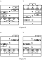
- the channel layer can include a first electrically insulating element 22 positioned between the hole electrode 12 and a second charge transport sublayer 8a , and/or a second electrically insulating element 24 positioned between the electron electrode 14 and the second charge transport sublayer 8a .
- first and second electrically insulating elements can be embedded within any of sublayers 8a , 8b , or 8c , for ease of fabrication (e.g., keeping the number of deposition/photolithography/etching steps to a minimum), the first and second electrically insulating elements can be deposited either on top of the charge transport sublayer 8a ( Figure 2a ) or on top of the emissive sublayer 8b ( Figure 2b ).
- the channel layer can include a first electrically insulating element 22 positioned between the hole electrode 12 and a second charge transport sublayer 8a , and/or a second electrically insulating element 24 positioned between the electron electrode 14 and the second charge transport sublayer 8a .
- first and second electrically insulating elements can be embedded within any of sublayers 8a , 8b , or 8c ; however, for ease of fabrication, the first and second electrically insulating elements can be deposited either on top of the charge transport sublayer 8c ( Figure 2c ) or on top of the emissive sublayer 8b ( Figure 2d ).
- OLETs have non-planar hole electrode and electron electrode.
- the hole electrode and the electron electrode can function, respectively, as the source electrode and the drain electrode (or vice versa) depending on the polarity of the gate voltage.
- the source electrode is typically grounded (0 V)
- the gate voltage is -100V and the drain voltage is - 80V
- the source electrode is the hole electrode (negatively biased) and the drain electrode is the electron electrode (positively biased).
- the gate voltage is +100V
- the source electrode is the electron electrode and the drain electrode is the hole electrode. Therefore, the present OLETs also can be described as having non-planar source electrode and drain electrode.
- an OLET 30a or 30b can have a hole electrode 12 and an electron electrode 14 that are offset vertically from each other.
- both the hole electrode 12 and the electron electrode 14 typically are positioned either on top of a first side 16 of the channel layer 8 or in contact with a second side 18 of the channel layer 8 .
- d1 refers to the distance from which the hole electrode is positioned away from the second side 18 of the channel layer
- d2 refers to the distance from which the electron electrode is positioned away from the second side 18 of the channel layer
- sublayer 8a can comprise a first semiconductor material having a thickness d S1
- sublayer 8c can comprise a second semiconductor material having a thickness d S2
- sublayer 8b can comprise an emissive material having a thickness d E .
- the hole electrode 12 and the electron electrode 14 can be positioned within different sublayers of the channel layer 8.
- d1 can be 0 (within sublayer 8a in contact with the second side 18 of the channel layer 8 )
- d2 can be d S1 (within sublayer 8b in contact with sublayer 8a ) or d2 can be d S1 + d E (within sublayer 8c in contact with sublayer 8b ).
- the gate electrode can have a length ( L G ) equal to or greater than the channel length ( L ), which is the distance between the edge 32 of the hole electrode 12 adjacent to the channel region and the edge 34 of the electron electrode 14 adjacent to the channel region.
- the gate electrode can have a length L G that is the same as the length of the channel region L and can be located within a space that is aligned with the channel region.
- the gate electrode 4 can be deposited on the substrate 2 , and the dielectric layer 6 can be formed over the gate electrode 4.
- the hole electrode 12 and the electron electrode 14 can be patterned on the dielectric layer 6 in a way such that an edge 32 of the hole electrode 12 and an edge 34 of the electron electrode 14 are aligned with the edges of the gate electrode 4.
- the hole electrode 12 and the electron electrode 14 first can be patterned on the substrate 2 .
- the active channel layer 8 can be formed (e.g. via sequential deposition of sublayers 8a , 8b , and 8c ) over the hole electrode 12 and the electron electrode 14 , followed by the deposition of the dielectric layer 6 over the channel layer 8 .
- the gate electrode 4 can be patterned on the dielectric layer, such that the edges of the gate electrode 4 are aligned with an edge 32 of the hole electrode 12 and an edge 34 of the electron electrode 14 .
- L can be between about 2 ⁇ m and about 500 ⁇ m, preferably between about 5 ⁇ m and about 20 ⁇ m.
- the hole electrode and the electron electrode, respectively can have a length L h and a length L e that independently are between about 50 ⁇ m and about 300 ⁇ m, preferably between about 100 ⁇ m and about 200 ⁇ m.
- the overlap b and b' of the gate electrode with either the hole electrode and/or the electron electrode can be 0 ⁇ m and up to the length ( L h or L e ) of the hole electrode and/or the electron electrode (i.e., 0 ⁇ b ⁇ L h , 0 ⁇ b' ⁇ L e ), but preferably, the overlap is between about 0 ⁇ m and about 100 ⁇ m. Accordingly, the length L G of the gate electrode can be between about 50 ⁇ m and about 500 ⁇ m, preferably between about 100 ⁇ m and about 200 ⁇ m.
- the thickness d S1 and d S2 of the two charge transport sublayers can be between about 5 ⁇ m and about 100 ⁇ m, whereas the thickness d E of the emissive sublayer can be between about 2 ⁇ m and about 50 ⁇ m.
- Figures 4-7 illustrate various examples, not forming part of the present invention and embodiments of OLETs having nonplanar hole and electron electrodes according to the present invention.
- the hole electrode and the electron electrode (or the electrical source and drain contacts) in a nonplanar architecture will greatly favor exciton formation in a trilayer OLET, thus enhancing device brightness.
- the source-drain electric field is parallel to the surface of the channel layer (indicated by the direction of the arrow).
- this architecture only the holes from the hole transport sublayer and the electrons from the electron transport sublayer that are electrostatically attracted into the emissive sublayer will recombine to form excitons. Therefore, the number of excitons that are actually formed often is a small fraction of the charge carriers moving through the charge transport sublayers.
- the source-drain electric field spans across the emissive sublayer 8b (as indicated by the direction of the arrow), that is, both hole and electron currents flow into the emissive sublayer. This results in a much greater probability for holes and electrons to meet in the emissive sublayer to form a larger number of excitons 26 . Furthermore, referring back to Figure 8a , because both the hole electrode and the electron electrode are deposited on the same surface and are in contact with a sublayer that favors the transport of only one type of charge carriers, large contact resistance inevitably results for one of the contacts.
- the contact resistance can be reduced drastically by positioning the hole electrode 12 in contact with sublayer 8a composed of a p-type semiconductor which facilitates hole transport, and positioning the electron electrode 14 in contact with sublayer 8c composed of an n-type semiconductor which facilitates electron transport.
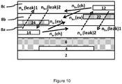
- n e - (leak)1 ⁇ n h + (leak)2 and n h + (leak) 1 ⁇ n e - (leak)2 charge carriers in these areas are unlikely to form excitons, and n e - (leak)1, n e - (leak)2 , n h + (leak)1 and n h + ( leak ) 2 can be considered leakage currents.
- FIG. 12 which shows an OLET including electrically insulating elements 22 and 24
- holes injected from the hole electrode 12 are expected to be localized in the hole transport sublayer 8a between the hole electrode 12 and the area above the electrically insulating element 24 while electrons injected from the electron electrode 14 are expected to be localized in the electron transport sublayer 8c between the electron electrode 14 and the area below the electrically insulating element 22 .
- the OLET shown in Figure 12 is expected to have a higher density of both holes and electrons within the channel region between the hole electrode 12 and the electron electrode 14 , more specifically, between the electrically insulating elements 22 and 24 , and in turn enhanced exciton formation can be expected.
- the incorporation of electrically insulating elements within the channel layer also allows more precise spatial control of where light is generated, and with less dependence upon gate voltage.
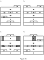
- an OLET according to the present teachings 100 can have a first electrically insulating element 22 and/or a second electrically insulating element 24 within the channel layer, and a hole electrode 12 and an electron electrode 14 that are offset vertically from each other.
- the hole electrode 14 can be positioned vertically away from a side (e.g., the bottom side 18 ) of the channel layer at a distance d1
- the electron electrode 14 can be positioned vertically away from the same side of the channel layer at a distance d2 .
- the distances d1 and d2 can be the same or different.
- both d1 and d2 can be 0, thereby providing a bottom-contact device.
- both d1 and d2 can be d S1 + d E + d S2 (where d S1 is the thickness of the first charge transport sublayer 8a, d E is the thickness of the emissive sublayer 8b , and d S2 is the thickness of the second charge transport sublayer 8c ), thereby providing a top-contact device.
- d1 can be 0 (within sublayer 8a in contact with the bottom side 18 of the channel layer 8 ), while d2 can be d S1 (within emissive sublayer 8b in contact with first charge transport sublayer 8a ).
- d1 can be 0 and d2 can be d S1 + d E (within second charge transport sublayer 8c in contact with emissive sublayer 8b ).
- the hole electrode 12 has a thickness d h and a length L h
- the electron electrode 14 has a thickness d e and a length L e .
- the hole electrode 12 is embedded within or otherwise positioned in contact with the hole transport sublayer 8a
- the electron electrode 14 is embedded within or otherwise positioned in contact with the electron transport sublayer 8c .
- d2 > d1 given that the hole transport sublayer 8a is positioned above the electron transport sublayer 8c .
- the electrically insulating element 22 which has a thickness d l1 can be positioned away from the bottom side 18 of the channel layer at a distance d3 , where d3 ⁇ d1 + d h .
- the electrically insulating element 24 which has a thickness d I2 can be positioned away from the bottom side 18 of the channel layer at a distance d4 , where d4 ⁇ d2 .
- d3 is no greater than d4
- d4 is no less than d3 .
- the length L I1 of the electrically insulating element 22 typically is between L h /2 and L h + L /3 S1 + d E
- the length L I2 of the electrically insulating element 24 can be between L e /2 and L e + L /3.
- L can be between about 2 ⁇ m and about 500 ⁇ m, preferably between about 5 ⁇ m and about 20 ⁇ m.
- the hole electrode and the electron electrode can have a length L h and a length L e that independently are between about 50 ⁇ m and about 300 ⁇ m, preferably between about 100 ⁇ m and about 200 ⁇ m.
- L h and L e are about 100 ⁇ m, and L also is about 100 ⁇ m
- L I1 and L I2 can be between about 50 ⁇ m and about 133 ⁇ m.
- the thickness d I1 and d I2 of the electrically insulating elements can be between about 5 ⁇ m and about 50 ⁇ m.
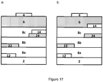
- FIGS 15-17 illustrate several preferred embodiments of OLETs according to the present teachings.
- Each of these OLETs has electrically insulating elements 22 and 24 below or above a pair of nonplanar hole electrode 12 and electron electrode 14.
- the hole electrode 12 is positioned in contact with the hole transport sublayer 8a
- the electron electrode 14 is positioned in contact with the electron transport sublayer 8c , to allow the best charge injection and transport.
- the electrically insulating elements are positioned in contact with the emissive sublayer 8b to maximize charge flow into the emissive sublayer within the channel region between the hole electrode and the electron electrode, thereby enhancing charge localization and device brightness.
- the electrically insulating elements 22 and 24 can be positioned on the same plane, and used in combination with planar or nonplanar hole electrode and electron electrode.
- the OLETs shown in Figures 2a, 2b, 2c, and 2d each have planar hole electrode and electron electrode, and the electrically insulating elements can be deposited on one of the charge transport sublayers 8a ( Figure 2a ) or 8c ( Figure 2c ), or on the emissive sublayer 8b ( Figures 2b and 2d ).
- the devices shown in Figure 2 can be fabricated with fewer shadow masks, deposition, and/or photolithography/etching steps, which in turn can result in lower fabrication costs.
- the electrically insulating elements 22 and 24 can have the same thickness as the emissive sublayer 8b , and the electrically insulating elements 22 and 24 together with the emissive sublayer 8b can form a single planar sublayer sandwiched between the two charge transport sublayers 8a and 8c .
- the electrically insulating elements tend to provide a smoother surface for further processing than the emissive material (which often comprises a mixture of host materials and emitters), the semiconductor film deposited thereon can be expected to have better morphology and the device as a whole can be expected to have better stack planarization.
- the OLETs described herein also can include charge injection layers.
- the hole electrode and the electron electrode can be coated with a hole injection layer and an electron injection layer, respectively, to further reduce contact resistance. More generally, a hole injection layer can be deposited between the hole transport sublayer and the hole electrode, and an electron injection layer can be deposited between the electron electrode and the electron transport sublayer.
- the present OLETs can include a surface-modified substrate, wherein the substrate is coated with a surface-modifier to allow improved processing such as better adhesion with the layer to be deposited thereon.
- the present OLETs also can include a passivation layer coupled to the top (first) side of the channel layer.
- the top charge transport sublayer comprises a metal oxide semiconductor, it may be preferred to have the metal oxide semiconductor layer covered by a passivation layer to improve device stability.
- OLETs can be fabricated using various deposition processes known in the art.
- an optional planarization or surface-modifying layer can be formed onto a transparent substrate, e.g., by spin-coating.
- a metallic thin film can be thermally evaporated thereon, followed by etching or other patterning techniques to form the gate electrode.
- the dielectric layer depending on its composition, can be deposited by a solution-phase process such as spin-coating or by chemical or physical vapor deposition. This can be followed by the formation of the active channel layer via sequential deposition of the first charge transport sublayer, the emissive sublayer, and the second charge transport sublayer.
- the hole electrode and the electron electrode can be formed using similar or different techniques as the gate electrode.
- the electrically insulating elements can be deposited in multiple steps, allowing formation of the electrically insulating elements within the channel layer.
- the electrically insulating elements can be formed by sputtering, ion-assisted deposition (IAD), atomic layer deposition, chemical vapor deposition, physical vapor deposition, different types of printing techniques (e.g., flexo printing, litho printing, gravure printing, ink-jetting, pad printing, and so forth), drop casting, dip coating, doctor blading, roll coating, and spin-coating. These techniques also can be used to form the channel layer and/or the dielectric layer.
- both the channel layer and the dielectric layer can be formed from a solution-phase process such as spin-coating, slot coating, or printing.
- Electrical contacts can be formed by processes such as, but not limited to, thermal evaporation and radiofrequency or e-beam sputtering, as well as various deposition processes, including but not limited to those described immediately above (e.g., flexo printing, litho printing, gravure printing, ink-jetting, pad printing, screen printing, drop casting, dip coating, doctor blading, roll coating, and spin-coating).
- the present OLETs can be fabricated on various substrates, including plastic, flexible substrates that have a low temperature resistance.
- flexible substrates include polyesters such as polyethylene terephthalate, polyethylene naphthalate, polycarbonate; polyolefins such as polypropylene, polyvinyl chloride, and polystyrene; polyphenylene sulfides such as polyphenylene sulfide; polyamides; aromatic polyamides; polyether ketones; polyimides; acrylic resins; polymethylmethacrylate, and blends and/or copolymers thereof.
- the substrate can be a rigid transparent substrate such as glass, quartz and VYCOR®.
- Substrate-gate materials commonly used in thin-film transistors also can be used. Examples include doped silicon wafer, tin-doped indium oxide (ITO) on glass, tin-doped indium oxide on polyimide or mylar film, aluminum or other metals alone or coated on a polymer such as polyethylene terephthalate, a doped polythiophene, and the like.
- ITO tin-doped indium oxide
- polyimide or mylar film aluminum or other metals alone or coated on a polymer such as polyethylene terephthalate, a doped polythiophene, and the like.
- the source/drain electrodes (or hole/electron electrodes) as well as the gate electrode can be made using various deposition techniques.
- the electrodes can be deposited through a mask, or can be deposited then etched or lifted off (photolithography). Suitable deposition techniques include electrodeposition, vaporization, sputtering, electroplating, coating, laser ablation and offset printing, from metal or metal alloy including copper, aluminum, gold, silver, molybdenum, platinum, palladium, and/or nickel, or an electrically conductive polymer such as polyethylenethioxythiophene (PEDOT).
- PEDOT polyethylenethioxythiophene
- Charge carrier injection can be facilitated by the use of a material for the injection electrode (hole electrode or electron electrode) that has a low barrier against injection of a charge carrier type into the hole transport sublayer and the electron transport sublayer, respectively.
- the hole electrode can comprise at least one material selected from the group consisting of Au, indium tin oxide, Cr, Cu, Fe, Ag, poly(3,4-ethylenedioxthiophene) combined with poly(styrenesulfonate) (PEDOT:PSS), and a perovskite manganite (Re 1-x A x MnO 3 ).
- the hole electrode and the electron electrode can be made of conductors with different work functions to favor both hole and electron injection.
- the dielectric layer can be composed of inorganic (e.g., oxides such as SiO 2 , Al 2 O 3 , or HfO 2 ; and nitrides such as Si 3 N 4 ), organic (e.g., polymers such as polycarbonate, polyester, polyimide, polystyrene, polyhaloethylene, polymethylmethacrylate), or hybrid organic/inorganic materials.
- inorganic e.g., oxides such as SiO 2 , Al 2 O 3 , or HfO 2 ; and nitrides such as Si 3 N 4
- organic e.g., polymers such as polycarbonate, polyester, polyimide, polystyrene, polyhaloethylene, polymethylmethacrylate
- hybrid organic/inorganic materials e.g., polymers such as polycarbonate, polyester, polyimide, polystyrene, polyhaloethylene, polymethylmethacrylate
- hybrid organic/inorganic materials e.g., polymers such as
- the dielectric layer can be formed via the growth of self-assembled nanodielectric materials (such as those described in Yoon et al., PNAS, 102 (13): 4678-4682 (2005 ), and Ha et al., Chem. Mater., 21(7): 1173-1175 (2009 )); solution-processing of inorganic/organic hybrid materials (e.g., as described in Ha et al., J. Am. Chem. Soc., 132 (49): 17428-17434 (2010 )); and low-temperature solution-processing of metal oxides (e.g., as described in International Publication Number WO 2012/103528 ).
- self-assembled nanodielectric materials such as those described in Yoon et al., PNAS, 102 (13): 4678-4682 (2005 ), and Ha et al., Chem. Mater., 21(7): 1173-1175 (2009 )
- solution-processing of inorganic/organic hybrid materials e.g
- the dielectric material can be in the form of a bilayer composed of different materials, for example, a combination of inorganic/organic materials, materials with different dielectric constants, or materials that can be processed by different techniques (e.g., solution-processing and vapor deposition). Any materials and methods of processing for gate dielectrics known in the art can be used in connection with the present electrically insulating elements.
- the channel layer various p-type semiconductors, n-type semiconductors, and organic electroluminescence semiconductors known in the art can be used according to the present teachings, respectively, as the hole transport sublayer, the electron transport sublayer, and the emissive sublayer in the present OLET.
- the channel layer can comprise small molecule materials, polymers, and/or metal complexes.
- Suitable materials for the electron transport (n-type) sublayer can include one class of n-type organic semiconductors (OSCs) that relates to oligomers, homopolymers or copolymers of thiophenes, particularly those substituted with fluorocarbons.
- OSCs n-type organic semiconductors
- ⁇ , ⁇ -diperfluorohexylquaterhiophenes and other fluorocarbon-substituted thiophene oligomers are described in U.S. Patent No. 6,585,914 .
- n-type OSCs relates to fused ring tetracarboxylic diimides and their derivatives.
- cyanated perylene diimides and cyanated naphthalene diimides more specifically, N,N'-bis-substituted-(1,7 & 1,6)-di-cyano-perylene-3,4:9,10-bis(dicarboximide)s and N,N'-bis-substituted 2,6-dicyanonaphthalene-1,4,5,8-bis(dicarboximide)s such as those described in U.S. Patent Nos. 7,671,202 , 7,902,363 , and 7,569,693 , and U.S.
- Patent Application Publication No. 2010/0319778 have been used as n-type semiconductors. Specific examples include N,N'-bis(cyclohexyl)-(1,7 & 1,6)-dicyano-perylene-3,4:9,10-bis(dicarboximide) (CN 2 PDI); N,N'-bis(1H-perfluorobutyl)-(1,7 & 1,6)-di-cyano-perylene-3,4:9,10-bis(dicarboximide); N,N'-bis(n-octyl)-(1,7 & 1,6)-di-cyano-perylene-3,4:9,10-bis(dicarboximide) (PDI-8CN 2 ); N,N'-bis(n-octyl)-2,6-di-cyanonaphthalene-1,4,5,8-bis(dicarboximide) (NDI-8CN 2 ); N,N'-bis(2-methylhexyl)-(
- n-type semiconductors relate to dicyanomethylene-substituted conjugated systems.
- U.S. Patent No. 7,928,249 describes dicyanomethylene-substituted fused ring compounds such as 2,8-di-(3-dodecylthien-2-yl)-indeno[1,2-b]fluorene-6,12-dimalonitrile; 2,8-dithien-2-yl-tetraphenylenedimalonitrile; and 2,8-di-(4'-dodecylthien-2'-yl]-4-dodecylthien-2-yl)-indeno[1,2-b]fluorene-6,12-dimalono-nitrile.
- Dicyanomethylene-substituted diketopyrrolopyrrole-containing quinoidal small molecules also have been investigated as n-type semiconductors. See Qiao et al., "Diketopyrrolopyrrole-Containing Quinoidal Small Molecules for High-Performance, Air-Stable, and Solution-Processable n-Channel Organic Field-Effect Transistors," J. Am. Chem. Soc., 134: 4084-4087 (2012 ).
- Thionated aromatic bisimides also can be used as n-type semiconductors. Examples include those described in International Publication Nos. WO2011/082234 such as (S,S)-PDIS 1 1MP, (S,S)- cis -PDIS 2 1MP, (S,S)- trans -PDIS 2 1MP, (S,S)-PDIS 3 1MP, (S,S)-PDIS 4 1MP, (S,S)- trans -PDIS 2 1Mhex, (R,R)- trans -PDIS 2 1Mhex, (S,R)- trans -PDIS 2 1Mhex, (R,S)- trans -PDIS 2 1Mhex, (R,R)- trans -PDIS 2 1Mhept, (S,S)- trans -PDIS 2 1MO, trans- PDIS 2 1Epr, cis -PDIS 2 1Epr, trans- PDIS 2 1M3MB, trans- PDIS 2 2 1M3MB, trans- P
- N-type semiconducting polymers also can be used according to the present teachings.
- n-type semiconducting polymers include oligomers, homopolymers and copolymers of naphthalenediimides described in U.S. Patent Application Publication No.
- linear acenes bent acenes, arylvinylenes, phenylenes, and fused (hetero)arenes including those substituted with alkylcarbonyl, arylcarbonyl, cyano and/or alkyl groups also can be suitable n-type semiconductor materials for use according to the present teachings.
- inorganic n-type OSCs can be used.
- solution-processable metal oxides e.g., ITO, indium oxide, indium zinc oxide, indium gallium zinc oxide
- chalcogenides e.g., CdSe
- U.S. Patent No. 8,017,458 and International Publication No. WO 2012/103528 are described in U.S. Patent No. 8,017,458 and International Publication No. WO 2012/103528 .
- Suitable materials for the hole transport (p-type) sublayer can include one class of p-type organic semiconductors (OSCs) that relates to oligothiophenes and polythiophenes.
- OSCs p-type organic semiconductors
- a dihexylquaterhiophene and other alkyl-substituted thiophene oligomers are described in Garnier et al., "Dihexylquaterthiophene, A Two-Dimensional Liquid Crystal-Like Organic Semiconductor with High Transport Properties," Chem. Mater., 10 (11): 3334-3339 (1998 ).
- Polythiophenes such as regioregular poly(3-hexylthiophene) (rr-P3HT) also can be used.
- Another class of p-type OSCs relates to soluble pentacene compounds such as those described in U.S. Patent No. 7,125,989 .
- Soluble pentacene compounds as exemplified by pentacene- N- sulfinyl-tert-butylcarbamate, can be obtained from Diels-Alder reaction of pentacene with hetero dienophiles.
- Another pentacene derivative, 6,13-bis(triisopropyl-silylethynyl)pentacene (TIPS pentacene) also has been shown to have reasonable solubility in common organic solvents.
- thienocoronene-based compounds described in International Publication No. WO2012/030662 . Specific examples include 1PB-thienocoronene, 2BO-thienocoronene, 1MP-thienocoronene, (S)-2MB-thienocoronene, undecanoxy-thienocoronene, and dodecyl-thienocoronene.
- alkylated [1]benzothieno[3,2-b]benzothiophenes and alkylated dinaphtho[2,3-b:2',3'-f]thieno[3,2-b]thiophenes have been reported as highly soluble p-type OSCs. See Ebata, H. et al., "Highly Soluble [1]Benzothieno[3,2-b]benzothiophenes (BTBT) Derivatives for High-Performance, Solution-Processed Organic Field-Effect Transistors," JACS, 129(51): 15732-15733 (2007 ); Ebata, H.
- exemplary classes of p-type semiconductors include phthalimide-based polymers, certain diketopyrrolopyrrole-based polymers, isoindigo-based conjugated polymers, See International Publication No. WO2010/117449 ; Li et al., "A High Mobility P-Type DPP-Thieno[3,2-b]thiophene Copolymer for Organic Thin-Film Transistors," Adv. Mater., 22: 4862-4866 (2010 ), Li et al., "Annealing-Free High-Mobility Diketopyrrolopyrrole-Quaterthiophene Copolymer for Solution-Processed Organic Thin Film Transistors," J. Am. Chem.
- linear acenes bent acenes, arylvinylenes, phenylenes, and fused (hetero)arenes including those substituted with alkyl and/or alkoxy groups also can be suitable p-type semiconductor materials for use according to the present teachings.
- the energy of the hole-transporting semiconductor material must match that of the electron transporting semiconductor material.
- the energy difference between the highest occupied molecular orbital (HOMO) of the hole-transporting semiconductor material and the lowest unoccupied molecular orbital (LUMO) of the electron-transporting semiconductor material should be, at a minimum, between about 1.6V and about 1.8 eV.
- the energy difference between the HOMO of the hole-transporting semiconductor material and the LUMO of the electron-transporting semiconductor material has to be, at a minimum, between about 2.2 eV and about 2.5 eV.
- the energy difference between the HOMO of the hole- transporting semiconductor material and the LUMO of the electron-transporting semiconductor material has to be, at a minimum, between about 2.8 eV and about 3.2 eV.
- the emissive sublayer can be a blend that includes a host material and a guest emitter selected from a fluorescent emitter and a phosphorescent emitter.
- the emissive sublayer can be prepared from a single-component host-emitting material. Suitable organic electroluminescent light-emitting materials include those having been used in OLED applications.
- the emissive sublayer can be composed of a blend of host tris(8-hydroxyquinolinato)aluminium (Alq 3 ) and guest 4-(dicyanomethylene)-2-methyl-6-(p-dimethylaminostyryl)-4H-pyran (DCM).
- Some exemplary host materials include polymers such as poly( p -phenylene vinylene), poly(alkyphenylphenylvinylene), poly(alkyphenylphenylvinylene-co-alkoxyphenylenevinylene), polyfluorene, poly(n-vinylcarbazole), and copolymers thereof.
- polymers such as poly( p -phenylene vinylene), poly(alkyphenylphenylvinylene), poly(alkyphenylphenylvinylene-co-alkoxyphenylenevinylene), polyfluorene, poly(n-vinylcarbazole), and copolymers thereof.
- Various carbazole compounds, triphenylamine compounds, including hybrids with oxadiazole or benzimidazole also have been used as host materials.
- Some exemplary guest emitters include fluorescent dyes such as various perylene derivatives, anthracene derivatives, rubrene derivatives, carbazole dervatives, fluorene derivatives, and quinacridone derivatives, and phosphorescent emitters such as various transition metal complexes including Ir, Os, or Pt.
- Some exemplary host-emitting materials include phosphorescent host-emitting compounds based on carbazole derivatives, fluorene derivatives, or 9-naphthylanthracene derivatives, and fluorescent host-emitting compounds based on organometallic chelates such as tris(8-quinolinol) aluminum complexes.
- the hole and electron injection layers can be prepared by self-assembly of thiolates, phosphonates, or aliphatic or aromatic carboxylates; by thermal evaporation of various charge transfer complexes and other heteroaromatic or organometallic complexes; or by thermal evaporation or sputtering of various metal oxides, fluorides, or carbonates.
- the hole injection layer and the electron injection layer can be made of materials that provide a staircase of electronic levels between the energy level of the hole electrode and the electron electrode, and the energy level required for injection into the hole transport sublayer and the electron transport sublayer, respectively.
- the present OLETs can be operated by applying a first appropriate bias voltage to the gate electrode, and injecting electrons from the electron electrode and holes from the hole electrode, while maintaining a second bias voltage between the latter two electrodes.
- the first and second bias voltages can be continuous voltages.
- the first and second bias voltages also can be pulsed voltages.
- a plurality of OLETs according to the present teachings can be arranged in a matrix to provide a display device.
- the display device can include optional driving and switching elements, compensating transistor elements, capacitors, and/or light-emitting diodes.
Landscapes
- Physics & Mathematics (AREA)
- Optics & Photonics (AREA)
- Electroluminescent Light Sources (AREA)
- Thin Film Transistor (AREA)
Applications Claiming Priority (4)
| Application Number | Priority Date | Filing Date | Title |
|---|---|---|---|
| US201261693288P | 2012-08-25 | 2012-08-25 | |
| US201261701760P | 2012-09-17 | 2012-09-17 | |
| US13/843,910 US9099670B2 (en) | 2012-08-25 | 2013-03-15 | Light-emitting transistors with improved performance |
| PCT/US2013/056532 WO2014035842A1 (en) | 2012-08-25 | 2013-08-23 | Light-emitting transistors with improved performance |
Publications (2)
| Publication Number | Publication Date |
|---|---|
| EP2888768A1 EP2888768A1 (en) | 2015-07-01 |
| EP2888768B1 true EP2888768B1 (en) | 2017-04-05 |
Family
ID=50147213
Family Applications (1)
| Application Number | Title | Priority Date | Filing Date |
|---|---|---|---|
| EP13763133.9A Active EP2888768B1 (en) | 2012-08-25 | 2013-08-23 | Light-emitting transistors with improved performance |
Country Status (6)
| Country | Link |
|---|---|
| US (3) | US8901547B2 (enExample) |
| EP (1) | EP2888768B1 (enExample) |
| JP (1) | JP6178966B2 (enExample) |
| KR (1) | KR101931409B1 (enExample) |
| CN (1) | CN104718638A (enExample) |
| WO (2) | WO2014035841A1 (enExample) |
Families Citing this family (35)
| Publication number | Priority date | Publication date | Assignee | Title |
|---|---|---|---|---|
| US8901547B2 (en) | 2012-08-25 | 2014-12-02 | Polyera Corporation | Stacked structure organic light-emitting transistors |
| KR102033097B1 (ko) * | 2012-11-05 | 2019-10-17 | 삼성디스플레이 주식회사 | 유기 발광 트랜지스터 및 유기 발광 표시 장치 |
| KR20150001528A (ko) * | 2013-06-27 | 2015-01-06 | 삼성전자주식회사 | 수직형 유기 발광 트랜지스터 및 이를 구비한 유기 엘이디 조명장치 |
| KR20150140504A (ko) * | 2014-06-05 | 2015-12-16 | 삼성디스플레이 주식회사 | 유기 발광 트랜지스터 |
| EP2960280A1 (en) | 2014-06-26 | 2015-12-30 | E.T.C. S.r.l. | Photocrosslinkable compositions, patterned high k thin film dielectrics and related devices |
| EP2978038A1 (en) | 2014-07-24 | 2016-01-27 | E.T.C. S.r.l. | Organic electroluminescent transistor |
| EP2978037A1 (en) * | 2014-07-24 | 2016-01-27 | E.T.C. S.r.l. | Organic electroluminescent transistor |
| CN111146352B (zh) * | 2014-07-24 | 2022-10-21 | 飞利斯有限公司 | 有机电致发光晶体管 |
| EP2978035A1 (en) | 2014-07-24 | 2016-01-27 | E.T.C. S.r.l. | Organic electroluminescent transistor |
| TWI545178B (zh) * | 2014-08-20 | 2016-08-11 | 中原大學 | Near infrared light emitting diode and its manufacturing method |
| WO2016072810A1 (ko) * | 2014-11-06 | 2016-05-12 | 포항공과대학교 산학협력단 | 엑시톤 버퍼층을 포함하는 페로브스카이트 발광 소자 및 이의 제조방법 |
| CN107210366B (zh) | 2014-11-06 | 2020-05-19 | 浦项工科大学校产学协力团 | 包含激子缓冲层的钙钛矿发光器件以及制造其的方法 |
| EP3021373A1 (en) * | 2014-11-14 | 2016-05-18 | E.T.C. S.r.l. | Display containing improved pixel architectures |
| WO2016100983A1 (en) | 2014-12-19 | 2016-06-23 | Polyera Corporation | Photocrosslinkable compositions, patterned high k thin film dielectrics and related devices |
| CN105355799A (zh) * | 2015-10-12 | 2016-02-24 | Tcl集团股份有限公司 | 一种量子点发光场效应晶体管及其制备方法 |
| KR102537438B1 (ko) | 2015-11-24 | 2023-05-30 | 삼성디스플레이 주식회사 | 화합물 및 이를 포함하는 유기 발광 소자 |
| KR102552273B1 (ko) | 2015-11-26 | 2023-07-07 | 삼성디스플레이 주식회사 | 축합환 화합물 및 이를 포함한 유기 발광 소자 |
| KR102546673B1 (ko) * | 2015-12-03 | 2023-06-23 | 삼성디스플레이 주식회사 | 유기 발광 소자 및 이를 포함하는 표시 장치 |
| CN105867018B (zh) * | 2016-03-28 | 2019-08-02 | 深圳市华星光电技术有限公司 | 石墨烯液晶显示装置、石墨烯发光元件及其制作方法 |
| JP6709706B2 (ja) * | 2016-08-30 | 2020-06-17 | Jxtgエネルギー株式会社 | 発光電気化学素子及び該発光電気化学素子を有する発光装置 |
| CN106449724A (zh) * | 2016-11-24 | 2017-02-22 | Tcl集团股份有限公司 | 顶发射量子点发光场效应晶体管及其制备方法 |
| CN107425035B (zh) * | 2017-05-11 | 2019-11-05 | 京东方科技集团股份有限公司 | 有机发光晶体管和显示面板 |
| KR102421769B1 (ko) * | 2017-11-13 | 2022-07-18 | 삼성디스플레이 주식회사 | 유기 발광 소자 및 이를 포함하는 유기 발광 표시장치 |
| WO2019139175A1 (en) * | 2018-01-09 | 2019-07-18 | Kyushu University, National University Corporation | Organic light-emitting field-effect transistor |
| WO2020101713A1 (en) | 2018-11-16 | 2020-05-22 | Hewlett-Packard Development Company, L.P. | Organic light emitting transistor |
| EP3664171B1 (en) * | 2018-12-06 | 2021-05-12 | Flexterra, Inc. | A thin-film transistor comprising organic semiconductor materials |
| CN111370587B (zh) * | 2018-12-25 | 2022-12-20 | 广东聚华印刷显示技术有限公司 | 发光晶体管及其制备方法 |
| CN112018257B (zh) * | 2019-05-30 | 2024-02-02 | 成都辰显光电有限公司 | 一种显示装置 |
| US11563186B2 (en) * | 2019-11-01 | 2023-01-24 | Samsung Electronics Co., Ltd. | Photoelectric devices having charge transport layer including first charge transport material and second charge transport material and sensors and electronic devices having the same |
| US12324302B2 (en) | 2020-02-11 | 2025-06-03 | Hewlett-Packard Development Company, L.P. | Dual plate OLET displays |
| TWI731616B (zh) * | 2020-03-09 | 2021-06-21 | 財團法人紡織產業綜合研究所 | 電致發光線 |
| WO2021202889A1 (en) | 2020-04-03 | 2021-10-07 | University Of Washington | Perovskite displays and methods of formation |
| TW202229165A (zh) * | 2020-09-30 | 2022-08-01 | 美商Ncx公司 | 共電沉積形成場發射陰極方法 |
| US20240057365A1 (en) * | 2020-12-25 | 2024-02-15 | Sharp Kabushiki Kaisha | Light emitting device |
| CN116096118A (zh) * | 2021-11-03 | 2023-05-09 | 京东方科技集团股份有限公司 | 发光器件及其控制方法、发光基板 |
Family Cites Families (57)
| Publication number | Priority date | Publication date | Assignee | Title |
|---|---|---|---|---|
| US5683823A (en) | 1996-01-26 | 1997-11-04 | Eastman Kodak Company | White light-emitting organic electroluminescent devices |
| US5747183A (en) | 1996-11-04 | 1998-05-05 | Motorola, Inc. | Organic electroluminescent light emitting material and device using same |
| JP2001319781A (ja) | 2000-05-02 | 2001-11-16 | Fuji Photo Film Co Ltd | 有機発光素子材料の選択方法及びその材料を用いた有機発光素子 |
| US6585914B2 (en) | 2000-07-24 | 2003-07-01 | Northwestern University | N-type thiophene semiconductors |
| JP4590089B2 (ja) | 2000-11-22 | 2010-12-01 | キヤノン株式会社 | 有機el素子 |
| US7125989B2 (en) | 2001-11-26 | 2006-10-24 | International Business Machines Corporation | Hetero diels-alder adducts of pentacene as soluble precursors of pentacene |
| US20060261329A1 (en) * | 2004-03-24 | 2006-11-23 | Michele Muccini | Organic electroluminescence devices |
| EP1609195B9 (en) | 2003-03-28 | 2011-08-31 | Michele Muccini | Organic electroluminescence devices |
| JP4423444B2 (ja) | 2003-04-08 | 2010-03-03 | スタンレー電気株式会社 | 発光型有機tft素子 |
| JP2005136383A (ja) * | 2003-10-09 | 2005-05-26 | Canon Inc | 有機半導体素子、その製造方法および有機半導体装置 |
| US7074502B2 (en) | 2003-12-05 | 2006-07-11 | Eastman Kodak Company | Organic element for electroluminescent devices |
| JP4530334B2 (ja) * | 2004-01-21 | 2010-08-25 | 国立大学法人京都大学 | 有機半導体装置、ならびにそれを用いた表示装置および撮像装置 |
| WO2005076815A2 (en) | 2004-01-26 | 2005-08-25 | Northwestern University | PERYLENE n-TYPE SEMICONDUCTORS AND RELATED DEVICES |
| CN100487930C (zh) * | 2004-08-30 | 2009-05-13 | 国立大学法人京都大学 | 有机半导体发光装置及使用它的显示装置 |
| WO2006098420A1 (ja) * | 2005-03-17 | 2006-09-21 | Pioneer Corporation | 発光素子及び表示装置 |
| JP4972727B2 (ja) | 2005-07-20 | 2012-07-11 | 日本電信電話株式会社 | 有機半導体発光素子およびそれを用いた表示装置、ならびに有機半導体発光素子の製造方法 |
| US20090140955A1 (en) | 2005-10-14 | 2009-06-04 | Pioneer Corporation | Light-emitting element and display device |
| JP4808479B2 (ja) * | 2005-11-28 | 2011-11-02 | 大日本印刷株式会社 | 有機発光トランジスタ素子及びその製造方法並びに発光表示装置 |
| JP2007200746A (ja) * | 2006-01-27 | 2007-08-09 | Dainippon Printing Co Ltd | 有機発光トランジスタ素子及びその製造方法並びに発光表示装置 |
| JP4809682B2 (ja) * | 2006-01-30 | 2011-11-09 | 大日本印刷株式会社 | 有機発光トランジスタ素子及びその製造方法並びに発光表示装置 |
| WO2007146250A2 (en) | 2006-06-12 | 2007-12-21 | Northwestern University | Naphthalene-based semiconductor materials and methods of preparing and use thereof |
| JP4934774B2 (ja) * | 2006-09-05 | 2012-05-16 | 大日本印刷株式会社 | 有機発光トランジスタ及び表示装置 |
| JPWO2008059817A1 (ja) * | 2006-11-14 | 2010-03-04 | 出光興産株式会社 | 有機薄膜トランジスタ及び有機薄膜発光トランジスタ |
| WO2008063609A2 (en) | 2006-11-17 | 2008-05-29 | Polyera Corporation | Diimide-based semiconductor materials and methods of preparing and using the same |
| US8203139B2 (en) * | 2006-11-24 | 2012-06-19 | Idemitsu Kosan Co., Ltd | Organic thin film transistor and organic thin film light-emitting transistor using an organic semiconductor layer having an aromatic hydrocarbon group or an aromatic heterocyclic group in the center thereof |
| US8431448B2 (en) * | 2006-12-28 | 2013-04-30 | Dai Nippon Printing Co., Ltd. | Organic transistor element, and method of manufacturing the same by concurrently doping an organic semiconductor layer and wet etching an electrode provided on the organic semiconductor layer |
| JP5228341B2 (ja) * | 2007-03-14 | 2013-07-03 | セイコーエプソン株式会社 | 有機エレクトロルミネッセンス素子の製造方法及び有機トランジスタの製造方法 |
| JP5465825B2 (ja) * | 2007-03-26 | 2014-04-09 | 出光興産株式会社 | 半導体装置、半導体装置の製造方法及び表示装置 |
| GB0706756D0 (en) | 2007-04-05 | 2007-05-16 | Imp Innovations Ltd | Improvements in organic field-effect transistors |
| TWI335681B (en) | 2007-05-18 | 2011-01-01 | Ind Tech Res Inst | White light organic electroluminescent element device |
| EP2185496A1 (en) | 2007-08-02 | 2010-05-19 | Northwestern University | Conjugated monomers and polymers and preparation and use thereof |
| TWI322141B (en) | 2007-08-28 | 2010-03-21 | Nat Univ Tsing Hua | Host material for blue oled and white light emitting device utilizing the same |
| JP5148211B2 (ja) * | 2007-08-30 | 2013-02-20 | 出光興産株式会社 | 有機薄膜トランジスタ及び有機薄膜発光トランジスタ |
| JP5299807B2 (ja) * | 2007-08-31 | 2013-09-25 | 出光興産株式会社 | ベンゾジチオフェン誘導体並びにそれを用いた有機薄膜トランジスタ及び有機薄膜発光トランジスタ |
| WO2009044614A1 (ja) | 2007-10-01 | 2009-04-09 | Rohm Co., Ltd. | 有機半導体装置 |
| US8017458B2 (en) | 2008-01-31 | 2011-09-13 | Northwestern University | Solution-processed high mobility inorganic thin-film transistors |
| US9219233B2 (en) | 2008-02-05 | 2015-12-22 | Basf Se | Semiconductor materials prepared from rylene-(π-acceptor)copolymers |
| JP5523351B2 (ja) | 2008-02-05 | 2014-06-18 | ビーエーエスエフ ソシエタス・ヨーロピア | ペリレン半導体並びにその製造方法及び使用 |
| KR101496846B1 (ko) * | 2008-12-24 | 2015-03-02 | 삼성디스플레이 주식회사 | 유기 발광 트랜지스터를 포함하는 표시 장치 및 이의 제조 방법 |
| WO2010117449A2 (en) | 2009-04-06 | 2010-10-14 | University Of Kentucky Research Foundation | Semiconducting compounds and devices incorporating same |
| GB0912034D0 (en) * | 2009-07-10 | 2009-08-19 | Cambridge Entpr Ltd | Patterning |
| JPWO2011055529A1 (ja) * | 2009-11-05 | 2013-03-28 | 出光興産株式会社 | 含ヘテロ環非対称性芳香族化合物、有機薄膜トランジスタ用化合物、及びそれを用いた有機薄膜トランジスタ |
| JP2011100938A (ja) | 2009-11-09 | 2011-05-19 | Nippon Shokubai Co Ltd | 有機発光素子、該有機発光素子を用いた表示装置、及び電子機器 |
| US8440828B2 (en) | 2009-12-29 | 2013-05-14 | Polyera Corporation | Organic semiconductors and devices incorporating same |
| US8212243B2 (en) | 2010-01-22 | 2012-07-03 | Eastman Kodak Company | Organic semiconducting compositions and N-type semiconductor devices |
| WO2011147523A1 (en) * | 2010-05-27 | 2011-12-01 | Merck Patent Gmbh | Formulation and method for preparation of organic electronic devices |
| EP2612376B1 (en) | 2010-08-29 | 2018-11-21 | Flexterra, Inc. | Semiconducting compounds and related compositions and devices |
| EP2649659B1 (en) * | 2010-12-07 | 2020-05-06 | University of Florida Research Foundation, Inc. | Active matrix display comprising a dilute source enabled vertical organic light emitting transistor |
| JPWO2012090462A1 (ja) * | 2010-12-28 | 2014-06-05 | 出光興産株式会社 | 有機半導体材料、当該材料を含んでなる塗布液、及び有機薄膜トランジスタ |
| EP2683718B1 (en) * | 2011-01-10 | 2017-05-24 | Basf Se | Thiocyanato substituted naphthalene diimide compounds and their use as n-type semiconductors |
| WO2012103528A2 (en) | 2011-01-28 | 2012-08-02 | Northwestern University | Low-temperature fabrication of metal oxide thin films and nanomaterial-derived metal composite thin films |
| JP5790095B2 (ja) * | 2011-04-01 | 2015-10-07 | ソニー株式会社 | 薄膜素子及びその製造方法、並びに、画像表示装置の製造方法 |
| EP2724389B1 (de) * | 2011-06-22 | 2018-05-16 | Novaled GmbH | Organisches elektronisches bauelement |
| US9214474B2 (en) * | 2011-07-08 | 2015-12-15 | Semiconductor Energy Laboratory Co., Ltd. | Semiconductor device and method for manufacturing semiconductor device |
| US10005879B2 (en) * | 2012-02-03 | 2018-06-26 | Basf Se | Method for producing an organic semiconductor device |
| US8878169B2 (en) * | 2012-02-07 | 2014-11-04 | Polyera Corporation | Photocurable polymeric materials and related electronic devices |
| US8901547B2 (en) | 2012-08-25 | 2014-12-02 | Polyera Corporation | Stacked structure organic light-emitting transistors |
-
2013
- 2013-03-14 US US13/830,283 patent/US8901547B2/en active Active
- 2013-03-15 US US13/843,910 patent/US9099670B2/en active Active
- 2013-08-23 KR KR1020157006622A patent/KR101931409B1/ko active Active
- 2013-08-23 WO PCT/US2013/056531 patent/WO2014035841A1/en not_active Ceased
- 2013-08-23 WO PCT/US2013/056532 patent/WO2014035842A1/en not_active Ceased
- 2013-08-23 CN CN201380053654.4A patent/CN104718638A/zh active Pending
- 2013-08-23 EP EP13763133.9A patent/EP2888768B1/en active Active
- 2013-08-23 JP JP2015528710A patent/JP6178966B2/ja active Active
-
2015
- 2015-08-03 US US14/817,203 patent/US9437842B2/en active Active
Non-Patent Citations (1)
| Title |
|---|
| None * |
Also Published As
| Publication number | Publication date |
|---|---|
| US20160036007A1 (en) | 2016-02-04 |
| WO2014035841A1 (en) | 2014-03-06 |
| US20140054613A1 (en) | 2014-02-27 |
| US9099670B2 (en) | 2015-08-04 |
| WO2014035842A1 (en) | 2014-03-06 |
| CN104718638A (zh) | 2015-06-17 |
| KR101931409B1 (ko) | 2018-12-20 |
| JP6178966B2 (ja) | 2017-08-16 |
| US20140054566A1 (en) | 2014-02-27 |
| US8901547B2 (en) | 2014-12-02 |
| EP2888768A1 (en) | 2015-07-01 |
| JP2015532768A (ja) | 2015-11-12 |
| KR20150046126A (ko) | 2015-04-29 |
| US9437842B2 (en) | 2016-09-06 |
Similar Documents
| Publication | Publication Date | Title |
|---|---|---|
| EP2888768B1 (en) | Light-emitting transistors with improved performance | |
| EP3172778B1 (en) | Organic electroluminescent transistor | |
| KR101394868B1 (ko) | 전류 증폭형 트랜지스터 소자 및 전류 증폭형 발광 트랜지스터 소자 | |
| WO2015048486A1 (en) | Frequency dependent light emitting devices | |
| US9825261B2 (en) | Organic electroluminescent transistor | |
| Shakutsui et al. | Improved efficiency of polymer light-emitting diodes by inserting a hole transport layer formed without thermal treatment above glass transition temperature | |
| TW200926475A (en) | Organic semiconductor light emitting device | |
| EP2978037A1 (en) | Organic electroluminescent transistor | |
| EP2978038A1 (en) | Organic electroluminescent transistor | |
| Marks | Materials Development | |
| Generali et al. | Multilayer approach in light-emitting transistors |
Legal Events
| Date | Code | Title | Description |
|---|---|---|---|
| PUAI | Public reference made under article 153(3) epc to a published international application that has entered the european phase |
Free format text: ORIGINAL CODE: 0009012 |
|
| 17P | Request for examination filed |
Effective date: 20150225 |
|
| AK | Designated contracting states |
Kind code of ref document: A1 Designated state(s): AL AT BE BG CH CY CZ DE DK EE ES FI FR GB GR HR HU IE IS IT LI LT LU LV MC MK MT NL NO PL PT RO RS SE SI SK SM TR |
|
| AX | Request for extension of the european patent |
Extension state: BA ME |
|
| DAX | Request for extension of the european patent (deleted) | ||
| GRAP | Despatch of communication of intention to grant a patent |
Free format text: ORIGINAL CODE: EPIDOSNIGR1 |
|
| INTG | Intention to grant announced |
Effective date: 20160323 |
|
| GRAJ | Information related to disapproval of communication of intention to grant by the applicant or resumption of examination proceedings by the epo deleted |
Free format text: ORIGINAL CODE: EPIDOSDIGR1 |
|
| GRAP | Despatch of communication of intention to grant a patent |
Free format text: ORIGINAL CODE: EPIDOSNIGR1 |
|
| INTC | Intention to grant announced (deleted) | ||
| INTG | Intention to grant announced |
Effective date: 20160722 |
|
| GRAS | Grant fee paid |
Free format text: ORIGINAL CODE: EPIDOSNIGR3 |
|
| GRAA | (expected) grant |
Free format text: ORIGINAL CODE: 0009210 |
|
| AK | Designated contracting states |
Kind code of ref document: B1 Designated state(s): AL AT BE BG CH CY CZ DE DK EE ES FI FR GB GR HR HU IE IS IT LI LT LU LV MC MK MT NL NO PL PT RO RS SE SI SK SM TR |
|
| REG | Reference to a national code |
Ref country code: GB Ref legal event code: FG4D |
|
| REG | Reference to a national code |
Ref country code: CH Ref legal event code: EP |
|
| REG | Reference to a national code |
Ref country code: AT Ref legal event code: REF Ref document number: 882561 Country of ref document: AT Kind code of ref document: T Effective date: 20170415 |
|
| REG | Reference to a national code |
Ref country code: IE Ref legal event code: FG4D |
|
| RAP2 | Party data changed (patent owner data changed or rights of a patent transferred) |
Owner name: FLEXTERRA, INC. |
|
| REG | Reference to a national code |
Ref country code: DE Ref legal event code: R096 Ref document number: 602013019497 Country of ref document: DE |
|
| REG | Reference to a national code |
Ref country code: NL Ref legal event code: MP Effective date: 20170405 |
|
| REG | Reference to a national code |
Ref country code: LT Ref legal event code: MG4D Ref country code: FR Ref legal event code: PLFP Year of fee payment: 5 |
|
| REG | Reference to a national code |
Ref country code: AT Ref legal event code: MK05 Ref document number: 882561 Country of ref document: AT Kind code of ref document: T Effective date: 20170405 |
|
| PG25 | Lapsed in a contracting state [announced via postgrant information from national office to epo] |
Ref country code: NL Free format text: LAPSE BECAUSE OF FAILURE TO SUBMIT A TRANSLATION OF THE DESCRIPTION OR TO PAY THE FEE WITHIN THE PRESCRIBED TIME-LIMIT Effective date: 20170405 |
|
| PG25 | Lapsed in a contracting state [announced via postgrant information from national office to epo] |
Ref country code: LT Free format text: LAPSE BECAUSE OF FAILURE TO SUBMIT A TRANSLATION OF THE DESCRIPTION OR TO PAY THE FEE WITHIN THE PRESCRIBED TIME-LIMIT Effective date: 20170405 Ref country code: AT Free format text: LAPSE BECAUSE OF FAILURE TO SUBMIT A TRANSLATION OF THE DESCRIPTION OR TO PAY THE FEE WITHIN THE PRESCRIBED TIME-LIMIT Effective date: 20170405 Ref country code: NO Free format text: LAPSE BECAUSE OF FAILURE TO SUBMIT A TRANSLATION OF THE DESCRIPTION OR TO PAY THE FEE WITHIN THE PRESCRIBED TIME-LIMIT Effective date: 20170705 Ref country code: ES Free format text: LAPSE BECAUSE OF FAILURE TO SUBMIT A TRANSLATION OF THE DESCRIPTION OR TO PAY THE FEE WITHIN THE PRESCRIBED TIME-LIMIT Effective date: 20170405 Ref country code: HR Free format text: LAPSE BECAUSE OF FAILURE TO SUBMIT A TRANSLATION OF THE DESCRIPTION OR TO PAY THE FEE WITHIN THE PRESCRIBED TIME-LIMIT Effective date: 20170405 Ref country code: GR Free format text: LAPSE BECAUSE OF FAILURE TO SUBMIT A TRANSLATION OF THE DESCRIPTION OR TO PAY THE FEE WITHIN THE PRESCRIBED TIME-LIMIT Effective date: 20170706 Ref country code: FI Free format text: LAPSE BECAUSE OF FAILURE TO SUBMIT A TRANSLATION OF THE DESCRIPTION OR TO PAY THE FEE WITHIN THE PRESCRIBED TIME-LIMIT Effective date: 20170405 |
|
| PG25 | Lapsed in a contracting state [announced via postgrant information from national office to epo] |
Ref country code: LV Free format text: LAPSE BECAUSE OF FAILURE TO SUBMIT A TRANSLATION OF THE DESCRIPTION OR TO PAY THE FEE WITHIN THE PRESCRIBED TIME-LIMIT Effective date: 20170405 Ref country code: PL Free format text: LAPSE BECAUSE OF FAILURE TO SUBMIT A TRANSLATION OF THE DESCRIPTION OR TO PAY THE FEE WITHIN THE PRESCRIBED TIME-LIMIT Effective date: 20170405 Ref country code: BG Free format text: LAPSE BECAUSE OF FAILURE TO SUBMIT A TRANSLATION OF THE DESCRIPTION OR TO PAY THE FEE WITHIN THE PRESCRIBED TIME-LIMIT Effective date: 20170705 Ref country code: RS Free format text: LAPSE BECAUSE OF FAILURE TO SUBMIT A TRANSLATION OF THE DESCRIPTION OR TO PAY THE FEE WITHIN THE PRESCRIBED TIME-LIMIT Effective date: 20170405 Ref country code: SE Free format text: LAPSE BECAUSE OF FAILURE TO SUBMIT A TRANSLATION OF THE DESCRIPTION OR TO PAY THE FEE WITHIN THE PRESCRIBED TIME-LIMIT Effective date: 20170405 Ref country code: IS Free format text: LAPSE BECAUSE OF FAILURE TO SUBMIT A TRANSLATION OF THE DESCRIPTION OR TO PAY THE FEE WITHIN THE PRESCRIBED TIME-LIMIT Effective date: 20170805 |
|
| REG | Reference to a national code |
Ref country code: DE Ref legal event code: R097 Ref document number: 602013019497 Country of ref document: DE |
|
| PG25 | Lapsed in a contracting state [announced via postgrant information from national office to epo] |
Ref country code: EE Free format text: LAPSE BECAUSE OF FAILURE TO SUBMIT A TRANSLATION OF THE DESCRIPTION OR TO PAY THE FEE WITHIN THE PRESCRIBED TIME-LIMIT Effective date: 20170405 Ref country code: CZ Free format text: LAPSE BECAUSE OF FAILURE TO SUBMIT A TRANSLATION OF THE DESCRIPTION OR TO PAY THE FEE WITHIN THE PRESCRIBED TIME-LIMIT Effective date: 20170405 Ref country code: RO Free format text: LAPSE BECAUSE OF FAILURE TO SUBMIT A TRANSLATION OF THE DESCRIPTION OR TO PAY THE FEE WITHIN THE PRESCRIBED TIME-LIMIT Effective date: 20170405 Ref country code: SK Free format text: LAPSE BECAUSE OF FAILURE TO SUBMIT A TRANSLATION OF THE DESCRIPTION OR TO PAY THE FEE WITHIN THE PRESCRIBED TIME-LIMIT Effective date: 20170405 Ref country code: DK Free format text: LAPSE BECAUSE OF FAILURE TO SUBMIT A TRANSLATION OF THE DESCRIPTION OR TO PAY THE FEE WITHIN THE PRESCRIBED TIME-LIMIT Effective date: 20170405 |
|
| PLBE | No opposition filed within time limit |
Free format text: ORIGINAL CODE: 0009261 |
|
| STAA | Information on the status of an ep patent application or granted ep patent |
Free format text: STATUS: NO OPPOSITION FILED WITHIN TIME LIMIT |
|
| PG25 | Lapsed in a contracting state [announced via postgrant information from national office to epo] |
Ref country code: SM Free format text: LAPSE BECAUSE OF FAILURE TO SUBMIT A TRANSLATION OF THE DESCRIPTION OR TO PAY THE FEE WITHIN THE PRESCRIBED TIME-LIMIT Effective date: 20170405 |
|
| 26N | No opposition filed |
Effective date: 20180108 |
|
| REG | Reference to a national code |
Ref country code: CH Ref legal event code: PL |
|
| PG25 | Lapsed in a contracting state [announced via postgrant information from national office to epo] |
Ref country code: MC Free format text: LAPSE BECAUSE OF FAILURE TO SUBMIT A TRANSLATION OF THE DESCRIPTION OR TO PAY THE FEE WITHIN THE PRESCRIBED TIME-LIMIT Effective date: 20170405 |
|
| PG25 | Lapsed in a contracting state [announced via postgrant information from national office to epo] |
Ref country code: LI Free format text: LAPSE BECAUSE OF NON-PAYMENT OF DUE FEES Effective date: 20170831 Ref country code: CH Free format text: LAPSE BECAUSE OF NON-PAYMENT OF DUE FEES Effective date: 20170831 |
|
| REG | Reference to a national code |
Ref country code: IE Ref legal event code: MM4A |
|
| PG25 | Lapsed in a contracting state [announced via postgrant information from national office to epo] |
Ref country code: SI Free format text: LAPSE BECAUSE OF FAILURE TO SUBMIT A TRANSLATION OF THE DESCRIPTION OR TO PAY THE FEE WITHIN THE PRESCRIBED TIME-LIMIT Effective date: 20170405 |
|
| REG | Reference to a national code |
Ref country code: BE Ref legal event code: MM Effective date: 20170831 |
|
| PG25 | Lapsed in a contracting state [announced via postgrant information from national office to epo] |
Ref country code: LU Free format text: LAPSE BECAUSE OF NON-PAYMENT OF DUE FEES Effective date: 20170823 |
|
| PG25 | Lapsed in a contracting state [announced via postgrant information from national office to epo] |
Ref country code: IE Free format text: LAPSE BECAUSE OF NON-PAYMENT OF DUE FEES Effective date: 20170823 |
|
| REG | Reference to a national code |
Ref country code: FR Ref legal event code: PLFP Year of fee payment: 6 |
|
| PG25 | Lapsed in a contracting state [announced via postgrant information from national office to epo] |
Ref country code: BE Free format text: LAPSE BECAUSE OF NON-PAYMENT OF DUE FEES Effective date: 20170831 |
|
| PG25 | Lapsed in a contracting state [announced via postgrant information from national office to epo] |
Ref country code: MT Free format text: LAPSE BECAUSE OF NON-PAYMENT OF DUE FEES Effective date: 20170823 |
|
| PG25 | Lapsed in a contracting state [announced via postgrant information from national office to epo] |
Ref country code: HU Free format text: LAPSE BECAUSE OF FAILURE TO SUBMIT A TRANSLATION OF THE DESCRIPTION OR TO PAY THE FEE WITHIN THE PRESCRIBED TIME-LIMIT; INVALID AB INITIO Effective date: 20130823 |
|
| PG25 | Lapsed in a contracting state [announced via postgrant information from national office to epo] |
Ref country code: CY Free format text: LAPSE BECAUSE OF FAILURE TO SUBMIT A TRANSLATION OF THE DESCRIPTION OR TO PAY THE FEE WITHIN THE PRESCRIBED TIME-LIMIT Effective date: 20170405 |
|
| PG25 | Lapsed in a contracting state [announced via postgrant information from national office to epo] |
Ref country code: MK Free format text: LAPSE BECAUSE OF FAILURE TO SUBMIT A TRANSLATION OF THE DESCRIPTION OR TO PAY THE FEE WITHIN THE PRESCRIBED TIME-LIMIT Effective date: 20170405 |
|
| PG25 | Lapsed in a contracting state [announced via postgrant information from national office to epo] |
Ref country code: TR Free format text: LAPSE BECAUSE OF FAILURE TO SUBMIT A TRANSLATION OF THE DESCRIPTION OR TO PAY THE FEE WITHIN THE PRESCRIBED TIME-LIMIT Effective date: 20170405 |
|
| PG25 | Lapsed in a contracting state [announced via postgrant information from national office to epo] |
Ref country code: PT Free format text: LAPSE BECAUSE OF FAILURE TO SUBMIT A TRANSLATION OF THE DESCRIPTION OR TO PAY THE FEE WITHIN THE PRESCRIBED TIME-LIMIT Effective date: 20170405 |
|
| PG25 | Lapsed in a contracting state [announced via postgrant information from national office to epo] |
Ref country code: AL Free format text: LAPSE BECAUSE OF FAILURE TO SUBMIT A TRANSLATION OF THE DESCRIPTION OR TO PAY THE FEE WITHIN THE PRESCRIBED TIME-LIMIT Effective date: 20170405 |
|
| REG | Reference to a national code |
Ref country code: DE Ref legal event code: R079 Ref document number: 602013019497 Country of ref document: DE Free format text: PREVIOUS MAIN CLASS: H01L0051520000 Ipc: H10K0050800000 |
|
| P01 | Opt-out of the competence of the unified patent court (upc) registered |
Effective date: 20230521 |
|
| PGFP | Annual fee paid to national office [announced via postgrant information from national office to epo] |
Ref country code: DE Payment date: 20250827 Year of fee payment: 13 |
|
| PGFP | Annual fee paid to national office [announced via postgrant information from national office to epo] |
Ref country code: IT Payment date: 20250820 Year of fee payment: 13 |
|
| PGFP | Annual fee paid to national office [announced via postgrant information from national office to epo] |
Ref country code: GB Payment date: 20250827 Year of fee payment: 13 |
|
| PGFP | Annual fee paid to national office [announced via postgrant information from national office to epo] |
Ref country code: FR Payment date: 20250825 Year of fee payment: 13 |