EP2886720A1 - Baumaschine, sowie ein Verfahren zum Abfräsen und Abtransportieren eines abgefrästen Materialstroms einer Baumaschine - Google Patents
Baumaschine, sowie ein Verfahren zum Abfräsen und Abtransportieren eines abgefrästen Materialstroms einer Baumaschine Download PDFInfo
- Publication number
- EP2886720A1 EP2886720A1 EP14193829.0A EP14193829A EP2886720A1 EP 2886720 A1 EP2886720 A1 EP 2886720A1 EP 14193829 A EP14193829 A EP 14193829A EP 2886720 A1 EP2886720 A1 EP 2886720A1
- Authority
- EP
- European Patent Office
- Prior art keywords
- conveyor belt
- shroud
- milled material
- conveyor
- construction machine
- Prior art date
- Legal status (The legal status is an assumption and is not a legal conclusion. Google has not performed a legal analysis and makes no representation as to the accuracy of the status listed.)
- Granted
Links
Images



Classifications
-
- E—FIXED CONSTRUCTIONS
- E01—CONSTRUCTION OF ROADS, RAILWAYS, OR BRIDGES
- E01C—CONSTRUCTION OF, OR SURFACES FOR, ROADS, SPORTS GROUNDS, OR THE LIKE; MACHINES OR AUXILIARY TOOLS FOR CONSTRUCTION OR REPAIR
- E01C23/00—Auxiliary devices or arrangements for constructing, repairing, reconditioning, or taking-up road or like surfaces
- E01C23/06—Devices or arrangements for working the finished surface; Devices for repairing or reconditioning the surface of damaged paving; Recycling in place or on the road
- E01C23/08—Devices or arrangements for working the finished surface; Devices for repairing or reconditioning the surface of damaged paving; Recycling in place or on the road for roughening or patterning; for removing the surface down to a predetermined depth high spots or material bonded to the surface, e.g. markings; for maintaining earth roads, clay courts or like surfaces by means of surface working tools, e.g. scarifiers, levelling blades
- E01C23/085—Devices or arrangements for working the finished surface; Devices for repairing or reconditioning the surface of damaged paving; Recycling in place or on the road for roughening or patterning; for removing the surface down to a predetermined depth high spots or material bonded to the surface, e.g. markings; for maintaining earth roads, clay courts or like surfaces by means of surface working tools, e.g. scarifiers, levelling blades using power-driven tools, e.g. vibratory tools
- E01C23/088—Rotary tools, e.g. milling drums
-
- E—FIXED CONSTRUCTIONS
- E01—CONSTRUCTION OF ROADS, RAILWAYS, OR BRIDGES
- E01C—CONSTRUCTION OF, OR SURFACES FOR, ROADS, SPORTS GROUNDS, OR THE LIKE; MACHINES OR AUXILIARY TOOLS FOR CONSTRUCTION OR REPAIR
- E01C23/00—Auxiliary devices or arrangements for constructing, repairing, reconditioning, or taking-up road or like surfaces
- E01C23/06—Devices or arrangements for working the finished surface; Devices for repairing or reconditioning the surface of damaged paving; Recycling in place or on the road
- E01C23/12—Devices or arrangements for working the finished surface; Devices for repairing or reconditioning the surface of damaged paving; Recycling in place or on the road for taking-up, tearing-up, or full-depth breaking-up paving, e.g. sett extractor
- E01C23/122—Devices or arrangements for working the finished surface; Devices for repairing or reconditioning the surface of damaged paving; Recycling in place or on the road for taking-up, tearing-up, or full-depth breaking-up paving, e.g. sett extractor with power-driven tools, e.g. oscillated hammer apparatus
- E01C23/127—Devices or arrangements for working the finished surface; Devices for repairing or reconditioning the surface of damaged paving; Recycling in place or on the road for taking-up, tearing-up, or full-depth breaking-up paving, e.g. sett extractor with power-driven tools, e.g. oscillated hammer apparatus rotary, e.g. rotary hammers
-
- B—PERFORMING OPERATIONS; TRANSPORTING
- B65—CONVEYING; PACKING; STORING; HANDLING THIN OR FILAMENTARY MATERIAL
- B65G—TRANSPORT OR STORAGE DEVICES, e.g. CONVEYORS FOR LOADING OR TIPPING, SHOP CONVEYOR SYSTEMS OR PNEUMATIC TUBE CONVEYORS
- B65G15/00—Conveyors having endless load-conveying surfaces, i.e. belts and like continuous members, to which tractive effort is transmitted by means other than endless driving elements of similar configuration
- B65G15/10—Conveyors having endless load-conveying surfaces, i.e. belts and like continuous members, to which tractive effort is transmitted by means other than endless driving elements of similar configuration comprising two or more co-operating endless surfaces with parallel longitudinal axes, or a multiplicity of parallel elements, e.g. ropes defining an endless surface
- B65G15/12—Conveyors having endless load-conveying surfaces, i.e. belts and like continuous members, to which tractive effort is transmitted by means other than endless driving elements of similar configuration comprising two or more co-operating endless surfaces with parallel longitudinal axes, or a multiplicity of parallel elements, e.g. ropes defining an endless surface with two or more endless belts
- B65G15/14—Conveyors having endless load-conveying surfaces, i.e. belts and like continuous members, to which tractive effort is transmitted by means other than endless driving elements of similar configuration comprising two or more co-operating endless surfaces with parallel longitudinal axes, or a multiplicity of parallel elements, e.g. ropes defining an endless surface with two or more endless belts the load being conveyed between the belts
- B65G15/16—Conveyors having endless load-conveying surfaces, i.e. belts and like continuous members, to which tractive effort is transmitted by means other than endless driving elements of similar configuration comprising two or more co-operating endless surfaces with parallel longitudinal axes, or a multiplicity of parallel elements, e.g. ropes defining an endless surface with two or more endless belts the load being conveyed between the belts between an auxiliary belt and a main belt
Definitions
- the invention relates to a self-propelled construction machine, in particular cold milling machine, recycler, surface miner according to the preamble of claim 1 and a method for milling and removal of a milled material flow according to the preamble of claim 11.
- the conveyor may have one or more conveyor belts which receive the material from the milling drum and unload at a discharge end along a discharge parabola.
- the loading of the milled material takes place during operation, ie while the road milling machine and the transport vehicle are in motion. It is important to transfer the milled material controlled on the transport vehicle, because otherwise the milled material is not unloaded to a desired discharge point and may affect the Wegifmonden traffic, or if the milled material does not land completely on the back of the transport vehicle, causing additional sweeping ,
- At least the last part of the conveying device in the conveying direction can preferably be mounted so as to be pivotable laterally and / or in height, wherein the throwing parabola can additionally be influenced with the aid of the adjustment of the conveying speed.
- the properties of the milled material are depending on the task, z. As fine milling or removal of complete pavements, as well as the set operating parameters, eg. As the feed rate of the road milling machine, the milling depth and the type of milled material, different.
- the amount of milled material per unit time, as well as its composition and the size of Fräsgutbruch Irishe may be different.
- the invention is therefore an object of the invention to provide a construction machine, and a method for milling and removal of a milled material flow of a construction machine, in which the discharge of the milled material is more predictable and reproducible adjustable.
- the invention provides in an advantageous manner that at least the last in the conveying direction section of the conveyor has at least one endlessly arranged over the conveyor belt shroud that extends substantially parallel to the conveyor belt and against the milled material on the conveyor belt at least in a portion of Length of the conveyor belt is applied.
- the shape and direction and bundling of the material flow can be set more precisely. Overall, a higher and more homogeneous discharge speed of the milled material can be achieved and a more accurate adjustment of the discharge speed, especially since a better transfer of force from the conveyor belt to the milled material can take place in the sense that less slippage occurs.
- the conveyor or the last section of the conveyor is arranged pivotably on the machine frame with respect to inclination and / or lateral alignment.
- the shroud is resiliently biased in the direction of the conveyor belt.
- the contact pressure can also be generated by the weight of the shroud.
- the shroud is height-adjustable and / or prestressed in the direction of the conveyor belt.
- the resilient mounting makes it possible to compensate for a part of the weight of the shroud or even increase the bias against the weight load or even push the lower strand dynamically against the milled material on the conveyor belt.
- the conveyor belt is bent, wherein in a transport position, a front, in the conveying direction last part of the conveyor belt is pivotable downwards.
- the shroud can preferably be made split, so that a total of two successively arranged shrouds are arranged above the conveyor belt.
- the last shroud in the transport direction together with the front part of the conveyor belt is preferably bent downwards. In this way, the transport length of a road milling machine can be significantly reduced.
- the shroud can also be arranged only in the region of the bendable front part of the conveyor belt.
- the conveyor belt has support rollers for the upper and lower run, and that the support rollers for the upper run of the conveyor belt in a direction orthogonal to the conveying direction plane on the upper run of the conveyor belt form a concave transport channel in cross-section.
- the shroud has support rollers for the upper and lower run of the shroud, and that the support rollers for the lower run of the shroud in a direction orthogonal to the conveying direction level flexible adaptation of the cross-sectional shape of the lower run of the shroud on to Allow the conveyor belt amount of milled material.
- the flexible adaptation of the cross-sectional shape of the lower run to the amount of material on the conveyor belt takes place dynamically at the point at which the support rollers are arranged.
- articulated support rollers of the lower run of the shroud are resiliently biased in the direction of the first conveyor belt.
- at least the support rollers for the upper run of the conveyor belt and the support rollers for the lower run of the shroud a plurality of pivotally coupled together roller segments.
- the segments of the upper run of the conveyor belt are mounted stationary, while the support rollers for the lower run of the shroud are movably mounted, so that the individual roller segments can assume different angular positions to each other.
- the conveying speed of the belts namely the conveyor belt and the at least one shroud can be variably and / or individually adjustable.
- the at least one shroud can diverge from this in the region of the discharge end before the end of the conveyor belt.
- the at least one shroud can project in the conveying direction over the end of the conveyor belt in the region of the discharge end.
- the shroud over the conveyor belt protrudes in the transport direction and the protruding part of the shroud is pivotable relative to the conveyor belt about a transverse and parallel to the width of the conveyor belt axis or arcuately guided around the end of the conveyor belt.
- the pivotability of the protruding part of the shroud makes it possible to influence the Abschparabel the milled material flow.
- the last guide roller of the shroud from a position in which the lower run of the shroud arcuately the end of the conveyor belt. in an angular range of about 90 °, to bring into a position in which the transport direction in the last guide roller is in a straight extension of the shroud.
- the trajectory parabola can be changed in such a way that the point of impact of the eroded material on a loading surface of a transport vehicle can be adjusted.
- the bands on the input side and output side each have a substantially rectilinear deflection roller, and that at least one, which is pivotable in the conveying direction last deflection rollers relative to the respective opposite guide roller. Due to the adjustability of the guide rollers at the discharge end, it is possible to bundle the material flow more strongly if necessary and, if necessary, to shorten the projecting parabola despite the high conveying speed, so that the discharge point moves closer to the conveying device.
- a method for milling and removal of a milled material flow of a road milling machine is provided that the milled material between a conveyor belt and at least one upper shroud of the Conveyor is transported at least over part of the length of the conveyor belt.
- the shroud can be resiliently biased at least in the part in contact with the milled material in the direction of the milled material carrying the lower conveyor belt.
- the milled material can be transported in a transport channel of the lower conveyor belt, wherein the lower run of the upper shroud is guided so that the strand is pressed with a cross-section depending on the amount of milled material convex to concave cross-sectional shape against the milled material.
- the milled material between them receiving bands can be performed on the input side converging and / or output side diverging.
- Fig. 1 shows a construction machine 1 for milling ground or traffic surfaces, which is also referred to as a cold planer.
- the cold milling machine has a chassis with, for example, four track drives, which carries the machine frame 2 of the road milling machine 1. It is understood that the crawler tracks can be wholly or partially substituted by wheels.
- a milling drum 6 is mounted, which extends transversely to the direction of travel.
- the setting of the milling depth is preferably carried out by means of the height adjustment of the track drives on lifting columns.
- cold planer is also referred to as a front loader road milling machine, since they can carry the milled material 3 in the direction of travel forward to a discharge point on a transport vehicle.
- a first conveyor belt 5 of a conveyor 18 is arranged, which preferably transfers the milled material 3 to a second conveyor belt 10.
- the road milling machine 1 may also have only a single conveyor belt, which may also be arranged at the rear of the road milling machine 1.
- cold milling machine shows a typical embodiment of a construction machine, in which a foldable conveyor 18 is used.
- a bendable conveyor belt is basically already out of the EP 2 113 613 A1 known.
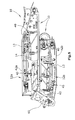
- Fig. 2 shows a partial section through the longitudinal center plane of the conveyor 18, which has a lower conveyor belt 10 and two successive upper shrouds 12a, 12b. At least one shroud 12a, 12b is arranged above the conveyor belt 10 of the conveyor 18, so that deviating from the in FIGS. shown embodiments, only a single shroud 12 may be disposed above the conveyor belt 10.
- the transport and shrouds 10, 12a, 12b are endlessly circulating belts which circulate about essentially rectilinear deflection rollers 20 to 25, wherein the forward deflection rollers 20, 22, 24 in the conveying direction 30 may preferably be driven deflection rollers, and wherein the conveying direction 30 Rear guide rollers (21, 23, 25) can also be performed crowned.
- the belts 10, 12a, 12b each have an upper run 13, 15 and a lower run 14, 16, the lower run 14 of the single shroud or shrouds 12a, 12b being biased towards the upper run 15 of the conveyor belt 10 can.
- the at least one shroud 12a, 12b may be height-adjustable in relation to the conveyor belt 10.
- the shrouds 12a, 12b may rest, due to their own weight, in each case with their lower run 14 on the conveyor belt 10 or the milled material 3 transported on the conveyor belt 10.
- the lateral guide devices 40 (FIG. Fig. 1 and Fig. 5 ), which are arranged on both sides of the cover and conveyor belts 10, 12a, 12b, can be combined with spring devices, so that the shrouds 12a, 12b do not rest with their full weight on the upper run 15 of the conveyor belt 10.
- the guide means 40 may also be set so that a certain distance between the racks 42a, 42b, 44 of the conveyor and shrouds 10, 12a, 12b can be preset.
- the guide elements 40 can also be combined alternatively with spring elements which bias the frame 42a, 42b of the at least one shroud 12a, 12b downwards.
- the one Section along the line III-III in Fig. 2 support rollers 32 are preferably provided for the upper run 15 of the conveyor belt 10, the roller segments 32a, 32b, 32c are hinged together and produce a cross-sectional concave bed for the milled material 3 with the upper strand 15.
- the support rollers 32 are preferably arranged stationarily in the frame 44.
- the lower run 14 of the at least one shroud 12a, 12b has movable support rollers 34, which may also be segmented and are hinged together in such a way that they move from one in Fig. 3 shown lowest position with minimal loading of the conveyor belt 10 to a position in the loaded state of the conveyor belt 10, as in Fig. 4 shown, can change.
- a transmission is provided, which guides the support rollers 34 in a substantially orthogonal plane to the shroud 12a and 12b.
- Each support roller 34 consists for example of three roller segments 34a, 34b, 34c, wherein all roller segments are guided for example by a four-bar linkage 50 on the frame 42a, 42b in the orthogonal plane.
- the support rollers 34 for the lower strand 14 of the shroud 12 a and 12 b may be provided with spring elements, for. B. Rosta blocks, be biased against the lower run 14.
- the upper support rollers 35 of the at least one shroud 12a, 12b and the lower support rollers 33 of the conveyor belt 10 may be rectilinear rollers which are stationary to the racks 42a, 42b, 44 stored.
- the transport or shrouds 10, 12a, 12b may have lateral guide means 46, each at the upper run 13, the at least one shroud or at the lower run 16, the conveyor belt at a certain altitude relative to the racks 42a, 42b , 44 are arranged to ensure lateral guidance.
- the shrouds 12a, 12b are on the input side between the guide rollers 23,25 and the first support roller 34 is preferably performed converging to the conveyor belt 10, while the output side towards the front in the conveying direction 30 guide rollers 22, 24 are preferably performed diverging.
- front guide roller 22 of the conveyor belt 30 preferably in the conveying direction 30 front guide roller 22 of the conveyor belt 30 last shroud 12b relative to the guide roller 20 of the conveyor belt 10 to be pivotally arranged so that the exit direction for the milled material 3 between the conveyor belt 10 and the at least one last shroud 12b set differently can be.
- the guide roller 20 of the conveyor belt 10 or both guide rollers 20, 22 may be pivotable.
- the upper run 15 of the conveyor belt 10 and the lower run 14 of the at least one shroud 12a, 12b move in the conveying direction 30 with the same, preferably adjustable conveying speed or with an adjustable different conveying speed.
- the shape of the throw parabola 9 can be influenced at the discharge end 11.
- Fig. 5 how out Fig. 5 can be seen, in a preferred embodiment, the front part 17 of the conveyor 18 are bent down and in a Fig. 5 apparent final position for transportation purposes are locked.
- An example of a suitable for this purpose swivel gear 60 is basically in the EP 2 113 613 A described. It is preferably provided that a separate shroud 12b is provided for the bent front part 17 of the conveyor 18. This division of the cover strip 12a, 12b arranged above the conveyor belt 10 makes it possible to retain the possibility of folding the conveyor belt 10.
- Fig. 6 shows an alternative embodiment of the support rollers 32 of the upper run 15 of the conveyor belt 10th
- a double arrangement of rectilinear support rollers 32 is used, which are arranged directly one behind the other in the conveying direction 30 and together allow in the conveying direction 30 V-shaped support of the upper run 15 of the conveyor belt 10.
- the transport and shrouds 10, 12a, 12b have a profiling on the milled material 3 facing surfaces that minimize the slip on the transport surface.
- Fig. 7 shows an embodiment in which an overhanging part 12c of the shroud 12b is pivotable to adjust the pitch parabola of the milled material flow 3 to a desired discharge point 27.
- the upper shroud 12b is extended beyond the deflecting roller 22 at the discharge end 11 and at a distance from the deflecting roller 22 has a further deflecting roller 26, which can be pivoted in the direction of the conveyor belt 10 about a normally horizontal axis 36, preferably coaxially to the axis of the deflecting roller 22 is.
- the part 12c protruding from the conveyor belt 10 can also be longer, such that the lower run 14 of the cover strip 12b, 12c can wrap around the conveyor belt 10 in the area of the guide roller 20, for example up to 90 °.
- the guide roller 26 can also, as in Fig. 7 shown in dashed lines, are brought into a position in which the pivotable portion 12c of the shroud 12b extends in a straight line extension to the rest of the shroud 12b. In this case results for the milled material 3 another parabola, which in Fig. 7 is shown in dashed lines.
Landscapes
- Engineering & Computer Science (AREA)
- Mining & Mineral Resources (AREA)
- Architecture (AREA)
- Civil Engineering (AREA)
- Structural Engineering (AREA)
- Mechanical Engineering (AREA)
- Structure Of Belt Conveyors (AREA)
- Road Repair (AREA)
Abstract
Description
- Die Erfindung betrifft eine selbstfahrende Baumaschine, insbesondere Kaltfräse, Recycler, Surface Miner nach dem Oberbegriff des Anspruchs 1 bzw. ein Verfahren zum Abfräsen und Abtransportieren eines abgefrästen Materialstroms nach dem Oberbegriff des Anspruchs 11.
- Beim Abtragen von Boden- oder Straßenmaterial mit einer Straßenfräsmaschine entsteht Fräsgut, das mittels einer Fördereinrichtung von der Straßenfräsmaschine auf ein Transportfahrzeug verladen wird. Die Fördereinrichtung kann dabei ein oder mehrere Transportbänder aufweisen, die das Material von der Fräswalze aufnehmen und an einem Abwurfende entlang einer Abwurfparabel abladen. Die Verladung des Fräsgutes erfolgt im laufenden Betrieb, d. h. während die Straßenfräsmaschine und das Transportfahrzeug in Bewegung sind. Dabei ist es von Bedeutung, das Fräsgut kontrolliert auf das Transportfahrzeug zu überführen, weil ansonsten das abgefräste Material nicht auf eine gewünschte Abwurfstelle abgeladen wird und den vorbeifließenden Verkehr beeinträchtigen kann, oder falls das Fräsgut nicht vollständig auf der Ladefläche des Transportfahrzeugs landet, zusätzliche Kehrarbeit verursacht.
- Um den Materialstrom zu lenken, kann zumindest der in Förderrichtung letzte Teil der Fördereinrichtung vorzugsweise seitlich und/oder in der Höhe schwenkbar gelagert sein, wobei zusätzlich mit Hilfe der Einstellung der Fördergeschwindigkeit, die Wurfparabel beeinflusst werden kann.
- Die Eigenschaften des abgefrästen Materials sind je nach Aufgabenstellung, z. B. Feinfräsen oder Ausbau kompletter Straßenbeläge, sowie von den eingestellten Betriebsparametern, z. B. die Vorschubgeschwindigkeit der Straßenfräsmaschine, die Frästiefe und die Art des abgefrästen Materials, unterschiedlich.
- Insbesondere kann die Menge des je Zeiteinheit abgefrästen Materials, sowie dessen Zusammensetzung und die Größe der Fräsgutbruchstücke unterschiedlich sein.
- Bekannt ist grundsätzlich die Verladung des abgefrästen Materials auf ein Transportfahrzeug mittels eines oder mehrerer aufeinanderfolgender Transportbänder.
- Bei Steilförderern ist es auch bekannt, einen Doppelgurt-Bandförderer zu verwenden (
EP 0 249 084 ). - Bei den bei Straßenfräsmaschinen bekannten einfachen Transportbändern kann sich aufgrund der Inhomogenität des Fräsgutes und der sich ändernden Menge des Fräsgutes ein diskontinuierlicher Materialstrom entstehen.
- Dies ist darin begründet, dass je nach Größe der Bruchstücke des abgefrästen Materials eine Relativbewegung der Bruchstücke untereinander und zum Transportband entstehen kann, nämlich insbesondere, wenn sich besonders viel oder besonders wenig Fräsgut auf dem Transportband befindet, oder bei schollenartigen Bruchstücken des abgefrästen Materials.
- Zwischen dem abgefrästen Material und dem Transportband kann ein variierender Schlupf entstehen, und zwar insbesondere bei einer hohen Geschwindigkeit des Transportbandes. Dies hat zur Folge, dass es zu unterschiedlichen Austrittsgeschwindigkeiten einzelner Bestandteile des abgefrästen Materials kommen kann, wobei außerdem von der vorgesehenen Wurfparabel abweichende Flugbahnen der unterschiedlichen Bruchstücke des abgefrästen Materials entstehen können. Eine weitere Folge ist, dass die effektive Austrittsgeschwindigkeit im Mittel niedriger ist, als die Geschwindigkeit des Transportbandes, wodurch ein Energieverlust entsteht.
- Außerdem ist ein verlangsamter Materialstrom anfälliger gegen äußere Beeinflussung, wie beispielsweise quer zum Transportband wirkende Windlasten, da die kinematische Energie in Förderrichtung verringert ist.
- Der Erfindung liegt daher die Aufgabe zugrunde, eine Baumaschine, sowie ein Verfahren zum Abfräsen und Abtransportieren eines abgefrästen Materialstroms einer Baumaschine anzugeben, bei der der Abwurf des abgefrästen Materials besser berechenbar und reproduzierbarer einstellbar ist.
- Zur Lösung dieser Aufgabe dienen die Merkmale des Anspruchs 1 bzw. 11.
- Die Erfindung sieht in vorteilhafter Weise vor, dass zumindest der in Förderrichtung letzte Abschnitt der Fördereinrichtung mindestens ein endlos umlaufendes über dem Transportband angeordnetes Deckband aufweist, das sich im Wesentlichen parallel zu dem Transportband erstreckt und gegen das abgefräste Material auf dem Transportband zumindest in einem Teilstück der Länge des Transportbandes anliegt.
- Die Erfindung hat folgende Vorteile:
- Durch die Anordnung mindestens eines Deckbandes über dem Transportband kann die Form und Richtung sowie Bündelung des Materialstroms präziser eingestellt werden. Insgesamt lässt sich eine höhere und homogenere Abwurfgeschwindigkeit des abgefrästen Materials erreichen und eine genauere Einstellung der Abwurfgeschwindigkeit, zumal eine bessere Kraftübertragung von dem Transportband zu dem abgefrästen Material in dem Sinne erfolgen kann, dass weniger Schlupf auftritt.
- Seitliche Abdichtungen, die bisher benötigt wurden und Reibungsverluste am Transportband erzeugten, werden vermieden, da die Abdichtung nun durch das aufliegende Deckband gewährleistet wird. Insgesamt ergibt sich eine bessere Energieeffizienz, wobei der Kraftstoffverbrauch reduziert werden kann und gesetzliche Vorgaben auch hinsichtlich der Schadstoffemission besser eingehalten werden können.
- Bei einer bevorzugten Ausführungsform ist vorgesehen, dass die Fördereinrichtung oder der letzte Abschnitt der Fördereinrichtung hinsichtlich Neigung und/oder seitlicher Ausrichtung schwenkbar an dem Maschinenrahmen angeordnet ist.
- Vorzugsweise ist das Deckband federnd in Richtung auf das Transportband vorspannbar. Dabei kann die Anpresskraft auch durch das Eigengewicht des Deckbandes erzeugt werden.
- Bei einer bevorzugten Ausführungsform ist vorgesehen, dass das Deckband höhenverstellbar und/oder in Richtung auf das Transportband vorspannbar gelagert ist. Die federnde Lagerung ermöglicht es, einen Teil des Gewichtes des Deckbandes zu kompensieren oder die Vorspannung gegenüber der Gewichtsbelastung sogar zu erhöhen oder auch nur den unteren Trum dynamisch gegen das abgefräste Material auf dem Transportband anzudrücken.
- Bei einer Weiterbildung der Erfindung ist vorgesehen, dass das Transportband abknickbar ist, wobei in einer Transportstellung ein vorderer, in Förderrichtung letzter Teil des Transportbandes nach unten verschwenkbar ist. Zu diesem Zweck kann das Deckband vorzugsweise geteilt ausgeführt sein, so dass insgesamt zwei hintereinander angeordnete Deckbänder über dem Transportband angeordnet sind. Dabei ist das in Transportrichtung letzte Deckband gemeinsam mit dem vorderen Teil des Transportbandes vorzugsweise nach unten abknickbar. Auf diese Weise kann die Transportlänge einer Straßenfräsmaschine signifikant verringert werden.
- Das Deckband kann auch nur im Bereich des abknickbaren vorderen Teils des Transportbandes angeordnet sein.
- Bei einer bevorzugten Ausführungsform ist vorgesehen, dass das Transportband Stützrollen für den oberen und unteren Trum aufweist, und dass die Stützrollen für den oberen Trum des Transportbandes in einer orthogonal zur Förderrichtung verlaufenden Ebene auf dem oberen Trum des Transportbandes eine im Querschnitt konkave Transportrinne bilden.
- Gemäß einer Weiterbildung ist vorgesehen, dass das Deckband Stützrollen für den oberen und unteren Trum des Deckbandes aufweist, und dass die Stützrollen für den unteren Trum des Deckbandes in einer orthogonal zur Förderrichtung verlaufenden Ebene eine flexible Anpassung der Querschnittsform des unteren Trums des Deckbandes an die auf dem Transportband befindliche Fräsgutmenge erlauben. Die flexible Anpassung der Querschnittsform des unteren Trums an die auf dem Transportband befindliche Fräsgutmenge erfolgt dynamisch jeweils an der Stelle, an der die Stützrollen angeordnet sind.
- Vorzugsweise ist vorgesehen, dass gelenkig befestigte Stützrollen des unteren Trums des Deckbandes federnd in Richtung auf das erste Transportband vorspannbar sind. Hierzu können zumindest die Stützrollen für den oberen Trum des Transportbandes und die Stützrollen für den unteren Trum des Deckbandes mehrere gelenkig miteinander gekoppelte Walzensegmente aufweisen. Dabei sind vorzugsweise die Segmente des oberen Trums des Transportbandes ortsfest gelagert, während die Stützrollen für den unteren Trum des Deckbandes beweglich gelagert sind, so dass die einzelnen Walzensegmente unterschiedliche Winkelstellungen zueinander annehmen können.
- Alternativ ist es auch möglich, die Stützrollen für den unteren Trum des Deckbandes jeweils in einer V-förmigen Doppelanordnung in Förderrichtung hintereinander vorzusehen.
- Die Fördergeschwindigkeit der Bänder, nämlich des Transportbandes und des mindestens einen Deckbandes kann variabel und/oder individuell einstellbar sein.
- Das mindestens eine Deckband kann im Bereich des Abwurfendes vor dem Ende des Transportbandes von diesem divergieren.
- Das mindestens eine Deckband kann im Bereich des Abwurfendes in Förderrichtung gesehen über das Ende des Transportbandes herausragen.
- Bei einer Ausführungsform kann vorgesehen sein, dass am Abwurfende das Deckband gegenüber dem Transportband in Transportrichtung übersteht und der überstehende Teil der Deckbandes relativ zum Transportband um eine quer und parallel zur Breite des Transportbandes verlaufende Achse verschwenkbar ist oder bogenförmig um das Ende des Transportbandes geführt ist. Die Verschwenkbarkeit des überstehenden Teils des Deckbandes ermöglicht es, die Abwurfparabel des abgefrästen Materialstroms zu beeinflussen.
- Bei einem solchen Ausführungsbeispiel, bei dem z.B. der untere Trum des Deckbandes bogenförmig um das Ende des Transportbandes geführt ist, besteht die Möglichkeit, die letzte Umlenkwalze des Deckbandes von einer Position, in der der untere Trum des Deckbandes bogenförmig das Ende des Transportbandes z.B. in einem Winkelbereich von ca. 90° umgibt, in eine Position zu bringen, in der sich die in Transportrichtung letzte Umlenkwalze in geradliniger Verlängerung des Deckbandes befindet.
- Ja nach Position dieser Umlenkwalze kann die Wurfparabel derart verändert werden, dass die Auftreffstelle des abgefrästen Materials auf einer Ladefläche eines Transportfahrzeuges einstellbar ist.
- Es kann auch vorgesehen sein, dass die Bänder eingangsseitig und ausgangsseitig jeweils eine im Wesentlichen geradlinige Umlenkwalze aufweisen, und dass wenigstens eine, der in Förderrichtung letzten Umlenkwalzen relativ zu der jeweils gegenüberliegenden Umlenkwalze verschwenkbar ist. Durch die Verstellbarkeit der Umlenkwalzen am Abwurfende besteht die Möglichkeit, den Materialstrom bei Bedarf stärker zu bündeln und ggf. die Wurfparabel trotz hoher Fördergeschwindigkeit zu verkürzen, so dass die Abwurfstelle näher an die Fördereinrichtung rückt.
- Bei einem Verfahren zum Abfräsen und Abtransportieren eines abgefrästen Materialstroms einer Straßenfräsmaschine ist vorgesehen, dass das abgefräste Material zwischen einem Transportband und mindestens einem oberen Deckband der Fördereinrichtung zumindest auf einem Teil der Länge des Transportbandes transportiert wird.
- Dabei kann das Deckband zumindest in dem mit dem abgefrästen Material in Kontakt befindlichen Teil in Richtung auf das das abgefräste Material tragende untere Transportband federnd vorgespannt werden.
- Das abgefräste Material kann in einer Transportrinne des unteren Transportbandes transportiert werden, wobei der untere Trum des oberen Deckbandes derart geführt wird, dass der Trum mit einer im Querschnitt je nach Menge des abgefrästen Materials konvexen bis konkaven Querschnittsform gegen das abgefräste Material angedrückt wird.
- Die das abgefräste Material zwischen sich aufnehmenden Bänder können eingangsseitig konvergierend und/oder ausgangsseitig divergierend geführt werden.
- Im Folgenden werden unter Bezugnahme auf die Zeichnungen Ausführungsbeispiele der Erfindung näher erläutert.
- Es zeigen:
- Fig. 1
- eine Straßenfräsmaschine,
- Fig. 2
- einen Schnitt durch die Fördereinrichtung gemäß
Fig. 1 in einer Längsmittelebene, - Fig. 3
- einen Schnitt entlang der Linie III-III in
Fig. 2 , - Fig. 4
- einen Schnitt entsprechend
Fig. 3 bei beladenem Transportband, - Fig. 5
- eine Seitenansicht der Fördereinrichtung im abgeknickten Zustand,
- Fig. 6
- eine alternative Gestaltung der Stützrollen für den unteren Trum des Transportbandes, und
- Fig. 7
- ein Ausführungsbeispiel mit einem überstehenden und verschwenkbaren Deckband.
-
Fig. 1 zeigt eine Baumaschine 1 zum Fräsen von Boden- oder Verkehrsflächen, die auch als Kaltfräse bezeichnet wird. - Die Kaltfräse weist ein Fahrwerk mit beispielsweise vier Kettenlaufwerken auf, das den Maschinenrahmen 2 der Straßenfräsmaschine 1 trägt. Es versteht sich, dass die Kettenlaufwerke durch Räder ganz oder teilweise substituiert werden können.
- In dem Maschinenrahmen 2 ist eine Fräswalze 6 gelagert, die sich quer zur Fahrtrichtung erstreckt. Die Einstellung der Frästiefe erfolgt vorzugsweise mit Hilfe der Höhenverstellung der Kettenlaufwerke über Hubsäulen. Die in
Fig. 1 dargestellte Kaltfräse wird auch als Frontladerstraßenfräse bezeichnet, da sie das abgefräste Material 3 in Fahrtrichtung nach vorne auf eine Abwurfstelle auf einem Transportfahrzeug befördern kann. In Fahrtrichtung vor der Fräswalze 6 ist ein erstes Transportband 5 einer Fördereinrichtung 18 angeordnet, das das abgefräste Material 3 vorzugsweise auf ein zweites Transportband 10 überträgt. Es versteht sich, dass die Straßenfräsmaschine 1 auch nur ein einziges Transportband aufweisen kann, wobei dieses auch am Heck der Straßenfräsmaschine 1 angeordnet sein kann. - Die in
Fig. 1 gezeigte Kaltfräse zeigt ein typisches Ausführungsbeispiel einer Baumaschine, bei der auch eine knickbare Fördereinrichtung 18 einsetzbar ist. Ein knickbares Transportband ist grundsätzlich bereits aus derEP 2 113 613 A1 bekannt. -
Fig. 2 zeigt einen Teilschnitt durch die Längsmittenebene der Fördereinrichtung 18, die ein unteres Transportband 10 und zwei aufeinanderfolgende obere Deckbänder 12a, 12b aufweist. Über dem Transportband 10 der Fördereinrichtung 18 ist mindestens ein Deckband 12a, 12b angeordnet, so dass abweichend von den in den Fign. gezeigten Ausführungsbeispielen auch nur ein einziges Deckband 12 über dem Transportband 10 angeordnet sein kann. - Die Transport- und Deckbänder 10, 12a, 12b sind endlos umlaufende Bänder, die um im Wesentlichen geradlinige Umlenkwalzen 20 bis 25 umlaufen, wobei die in Förderrichtung 30 vorderen Umlenkwalzen 20, 22, 24 vorzugsweise angetriebene Umlenkwalzen sein können, und wobei die in Förderrichtung 30 hinteren Umlenkwalzen (21, 23, 25) auch ballig ausgeführt sein können.
- Die Bänder 10, 12a, 12b weisen jeweils einen oberen Trum 13, 15 und einen unteren Trum 14, 16 auf, wobei der untere Trum 14 des einzigen Deckbandes oder der Deckbänder 12a, 12b in Richtung auf den oberen Trum 15 des Transportbandes 10 vorgespannt sein kann.
- Insgesamt kann das mindestens eine Deckband 12a, 12b in Relation zu dem Transportband 10 höhenverstellbar sein. Hierzu weist die Fördereinrichtung 18 ein Gestell 44 für das Transportband 10 und Gestelle 42a, 42b für die Deckbänder 12a, 12b auf, an denen seitlich Führungselemente 40 vorgesehen sind, die eine Höhenverstellung des mindestens einen Deckbandes 12a, 12b in Relation zu dem Transportband 10 ermöglichen.
- Dabei können die Deckbänder 12a, 12b aufgrund ihres Eigengewichtes jeweils mit ihrem unteren Trum 14 auf dem Transportband 10 bzw. dem auf dem Transportband 10 transportierten abgefrästen Material 3 aufliegen.
- Die seitlichen Führungseinrichtungen 40 (
Fig. 1 undFig. 5 ), die beiderseits der Deck- und Transportbänder 10, 12a, 12b angeordnet sind, können mit Federeinrichtungen kombiniert sein, so dass die Deckbänder 12a, 12b nicht mit ihrem vollständigen Gewicht auf dem oberen Trum 15 des Transportbandes 10 aufliegen. - Selbstverständlich können die Führungseinrichtungen 40 auch so eingestellt sein, dass ein bestimmter Abstand zwischen den Gestellen 42a, 42b, 44 der Transport- und Deckbänder 10, 12a, 12b fest voreingestellt sein kann.
- Die Führungselemente 40 können auch alternativ mit Federelementen kombiniert sein, die das Gestell 42a, 42b des mindestens einen Deckbandes 12a, 12b nach unten vorspannen. Wie am besten aus den
Fign. 3 und 4 ersichtlich, die einen Schnitt entlang der Linie III-III inFig. 2 darstellen, sind für den oberen Trum 15 des Transportbandes 10 vorzugsweise Stützrollen 32 vorgesehen, deren Walzensegmente 32a, 32b, 32c gelenkig miteinander verbunden sind und ein im Querschnitt konkaves Bett für das abgefräste Material 3 mit dem oberen Trum 15 erzeugen. Die Stützrollen 32 sind dabei vorzugsweise ortsfest in dem Gestell 44 angeordnet. - Der untere Trum 14 des mindestens einen Deckbandes 12a, 12b weist bewegliche Stützrollen 34 auf, die ebenfalls segmentiert sein können und gelenkig derart miteinander verbunden sind, dass sie von einer in
Fig. 3 gezeigten untersten Position mit minimaler Beladung des Transportbandes 10 zu einer Position im beladenen Zustand des Transportbandes 10, wie inFig. 4 gezeigt, wechseln können. Hierzu ist beispielsweise ein Getriebe vorgesehen, das die Stützrollen 34 in einer im Wesentlichen orthogonalen Ebene zu dem Deckband 12a bzw. 12b führt. Jede Stützrolle 34 besteht dabei beispielsweise aus drei Walzensegmenten 34a, 34b, 34c, wobei alle Walzensegmente beispielsweise von einem Viergelenkgetriebe 50 an dem Gestell 42a, 42b in der orthogonalen Ebene geführt werden. - Die Stützrollen 34 für den unteren Trum 14 des Deckbandes 12a bzw. 12b können mit Federelementen, z. B. Rosta-Blocks, gegen den unteren Trum 14 vorgespannt sein.
- Die oberen Stützrollen 35 des mindestens einen Deckbandes 12a, 12b und die unteren Stützrollen 33 des Transportbandes 10 können geradlinige Walzen sein, die ortsfest zu den Gestellen 42a, 42b, 44 gelagert sind.
- Darüber hinaus können die Transport- bzw. Deckbänder 10, 12a, 12b seitliche Führungseinrichtungen 46 aufweisen, die jeweils am oberen Trum 13, des mindestens einen Deckbandes bzw. am unteren Trum 16, des Transportbandes in einer bestimmten Höhenlage relativ zu den Gestellen 42a, 42b, 44 angeordnet sind, um eine seitliche Führung zu gewährleisten. Die Deckbänder 12a, 12b sind eingangsseitig zwischen den Umlenkwalzen 23,25 und der ersten Stützrolle 34 vorzugsweise konvergierend zu dem Transportband 10 geführt, während sie ausgangsseitig in Richtung auf die in Förderrichtung 30 vorderen Umlenkwalzen 22, 24 vorzugsweise divergierend geführt sind.
- Dabei kann vorzugsweise die in Förderrichtung 30 vordere Umlenkwalze 22 des in Förderrichtung 30 letzten Deckbandes 12b relativ zur Umlenkwalze 20 des Transportbandes 10 schwenkbar angeordnet sein, so dass die Austrittsrichtung für das abgefräste Material 3 zwischen dem Transportband 10 und dem mindestens einen letzten Deckband 12b unterschiedlich eingestellt werden kann. Alternativ können auch die Umlenkwalze 20 des Transportbandes 10 oder beide Umlenkwalzen 20, 22 verschwenkbar sein.
- Der obere Trum 15 des Transportbandes 10 und der jeweils untere Trum 14 des mindestens einen Deckbandes 12a, 12b bewegen sich in Förderrichtung 30 mit gleicher, vorzugsweise einstellbarer Fördergeschwindigkeit oder mit einer einstellbaren unterschiedlichen Fördergeschwindigkeit. Mit Hilfe der Fördergeschwindigkeit und der Höheneinstellung der Fördereinrichtung 18 sowie der Einstellung des Abstandes bzw. des Schwenkwinkels zwischen dem letzten Deckband 12b und dem Transportband 10 kann die Form der Wurfparabel 9 am Abwurfende 11 beeinflusst werden.
- Wie aus
Fig. 5 ersichtlich ist, kann bei einem bevorzugten Ausführungsbeispiel der vordere Teil 17 der Fördereinrichtung 18 nach unten abgeknickt werden und in einer ausFig. 5 ersichtlichen Endposition für Transportzwecke arretiert werden. Ein Beispiel für ein hierfür geeignetes Schwenkgetriebe 60 ist grundsätzlich in derEP 2 113 613 A beschrieben. Vorzugsweise ist vorgesehen, dass für den abgeknickten vorderen Teil 17 der Fördereinrichtung 18 ein eigenes Deckband 12b vorgesehen ist. Diese Aufteilung des über dem Transportband 10 angeordneten Deckbandes 12a, 12b ermöglicht die Beibehaltung der Abknickmöglichkeit für das Transportband 10. -
Fig. 6 zeigt eine alternative Ausführungsform für die Stützrollen 32 des oberen Trums 15 des Transportbandes 10. - Bei diesem Ausführungsbeispiel wird eine Doppelanordnung von geradlinigen Stützwalzen 32 verwendet, die unmittelbar hintereinander in Förderrichtung 30 angeordnet sind und gemeinsam eine in Förderrichtung 30 V-förmige Abstützung des oberen Trums 15 des Transportbandes 10 ermöglichen.
- Die Transport- und Deckbänder 10, 12a, 12b weisen eine Profilierung auf den dem abgefrästen Material 3 zugewandten Flächen auf, die den Schlupf auf der Transportoberfläche minimieren.
-
Fig. 7 zeigt ein Ausführungsbeispiel, bei dem ein überstehender Teil 12c des Deckbandes 12b verschwenkbar ist, um die Wurfparabel des abgefrästen Materialstroms 3 auf eine gewünschte Abwurfstelle 27 einzustellen. - Das obere Deckband 12b ist am Abwurfende 11 über die Umlenkwalze 22 hinaus verlängert und weist mit Abstand von der Umlenkwalze 22 eine weitere Umlenkwalze 26 auf, die in Richtung auf das Transportband 10 um eine normalerweise horizontale Achse 36, vorzugsweise koaxial zur Achse der Umlenkwalze 22 schwenkbar ist.
- Es versteht sich, dass abweichend von der Darstellung in
Fig. 7 der gegenüber dem Transportband 10 überstehende Teil 12c auch länger sein kann, derart, dass der untere Trum 14 des Deckbandes 12b, 12c das Transportband 10 im Bereich der Umlenkwalze 20 z.B. bis zu 90° bogenförmig umschlingen kann. - Die Umlenkwalze 26 kann auch, wie in
Fig. 7 gestrichelt dargestellt, in eine Position gebracht werden, in der der schwenkbare Teil 12c des Deckbandes 12b in geradliniger Verlängerung zu dem restlichen Deckband 12b verläuft. In diesem Fall ergibt sich für das abgefräste Material 3 eine andere Wurfparabel, die inFig. 7 gestrichelt dargestellt ist. - Es ist daher möglich, mit der Schwenkstellung des überstehenden Teils 12c die Lage der Abwurfstelle 27 auf einer Ladefläche 28 eines Transportfahrzeuges zu bestimmen.
Claims (15)
- Baumaschine (1), insbesondere Kaltfräse, Recycler oder Surface Miner, zum Bearbeiten von Bodenoberflächen, mit einer an einem Maschinenrahmen (2) gelagerten Fräswalze (8) und einer Fördereinrichtung (18), die das abgefräste Material (3) von der Fräswalze (8) im fahrenden Arbeitsbetrieb übernimmt und über wenigstens ein, endlos umlaufendes Transportband (10) in Förderrichtung (30) an einem Abwurfende (11) entlang einer Wurfparabel (9) auf eine Abwurfstelle ablädt,
dadurch gekennzeichnet, dass
zumindest der in Förderrichtung (30) letzte Abschnitt der Fördereinrichtung (18) mindestens ein endlos umlaufendes, über dem Transportband (10) angeordnetes Deckband (12a, 12b) aufweist, das sich im Wesentlichen parallel zu dem Transportband (10) erstreckt und gegen das abgefräste Material (3) auf dem Transportband (10) zumindest in einem Teilstück der Länge des Transportbandes (10) anliegt. - Baumaschine nach Anspruch 1, dadurch gekennzeichnet, dass die Fördereinrichtung (18) oder der letzte Abschnitt der Fördereinrichtung (18) hinsichtlich Neigung und/oder seitlicher Ausrichtung schwenkbar an dem Maschinenrahmen (2) angeordnet ist.
- Baumaschine (1) nach Anspruch 1, dadurch gekennzeichnet, dass das Deckband (12a, 12b) höhenverstellbar und/oder in Richtung auf das Transportband (10) vorspannbar gelagert ist.
- Baumaschine (1) nach einem der Ansprüche 1 bis 3, dadurch gekennzeichnet, dass auf dem Transportband (10) zwei aufeinanderfolgende Deckbänder (12a, 12b) angeordnet sind.
- Baumaschine (1) nach einem der Ansprüche 1 bis 4, dadurch gekennzeichnet, dass das Transportband (10) abknickbar ist, wobei in einer Transportstellung ein vorderer Teil (17) des Transportbandes (10) nach unten verschwenkbar ist, und dass vorzugsweise im Bereich des abknickbaren vorderen Teils (17) des Transportbandes (10) ein Deckband (12b) angeordnet ist.
- Baumaschine (1) nach einem der Ansprüche 1 bis 5, dadurch gekennzeichnet, dass das Transportband (10) Stützrollen (32, 33) für den oberen und unteren Trum (15, 16) aufweist, und dass die Stützrollen (32) für den oberen Trum (15) des Transportbandes (10) in einer orthogonal zur Förderrichtung (30) verlaufenden Ebene auf dem oberen Trum (15) des Transportbandes (10) eine im Querschnitt konkave Transportrinne bilden.
- Baumaschine (1) nach einem der Ansprüche 1 bis 6, dadurch gekennzeichnet, dass das mindestens eine Deckband (12a, 12b) Stützrollen (34, 35) für den oberen und unteren Trum (13, 14) des Deckbandes (12a, 12b) aufweist, und dass die Stützrollen (34) für den unteren Trum (14) des Deckbandes (12a, 12b) in einer orthogonal zur Förderrichtung (30) verlaufenden Ebene eine flexible Anpassung der Querschnittsform des unteren Trums (14) des Deckbandes (12a, 12b) an die auf dem Transportband (10) befindliche Fräsgutmenge erlauben.
- Straßenfräsmaschine (1) nach einem der Ansprüche 6 oder 7, dadurch gekennzeichnet, dass zumindest die Stützrollen (32) für den oberen Trum (15) des Transportbandes (10) und/oder die Stützrollen (34) für den unteren Trum (14) des Deckbandes (12a, 12b) mehrere gelenkig miteinander gekoppelte Walzensegmente aufweisen.
- Baumaschine (1) nach einem der Ansprüche 1 bis 8, dadurch gekennzeichnet, dass das Deckband (12a, 12b) ausgangsseitig von dem Transportband (10) divergiert und/oder eingangsseitig zu dem Transportband konvergiert.
- Baumaschine (1) nach einem der Ansprüche 1 bis 9, dadurch gekennzeichnet, dass am Abwurfende (11) das Deckband (12b) gegenüber dem Transportband (10) in Transportrichtung übersteht und der überstehende Teil des Deckbandes (12b) relativ zum Transportband (10) um eine quer zur Länge und parallel zur Breite des Transportbandes (10) verlaufende Achse (36) verschwenkbar ist oder bogenförmig um das Ende des Transportbandes (10) in unterschiedliche Schwenkstellungen überführbar ist.
- Verfahren zum Abfräsen und Abtransportieren eines abgefrästen Materialstroms einer Baumaschine (1), insbesondere Kaltfräse, Recycler oder Surface Miner, bei der das abgefräste Material (3) im Fräsbetrieb von der Fräswalze (6) übernommen wird und an einem Abwurfende (12) einer hinsichtlich Fördergeschwindigkeit einstellbaren Fördereinrichtung (18) entlang einer Wurfparabel (9) auf eine Abwurfstelle abgeladen wird, dadurch gekennzeichnet, dass
das abgefräste Material (3) zwischen einem unteren Transportband (10) und mindestens einem oberen Deckband (12a, 12b) der Fördereinrichtung (18) zumindest auf einem Teil der Länge des Transportbandes (10) transportiert wird. - Verfahren nach Anspruch 11, dadurch gekennzeichnet, dass das Deckband (12a, 12b) zumindest in dem mit dem abgefrästen Material (3) in Kontakt befindlichen Teil in Richtung auf das abgefräste Material (3) tragende Transportband (10) federnd vorgespannt wird.
- Verfahren nach Anspruch 11 oder 12, dadurch gekennzeichnet, dass zum Transport der Straßenfräsmaschine (1) ein vorderer Teil (17) der Fördereinrichtung (18) abgeknickt und arretiert wird.
- Verfahren nach einem der Ansprüche 11 bis 13, dadurch gekennzeichnet, dass das abgefräste Material (3) in einer Transportrinne des unteren Transportbandes (10) transportiert wird und dass der untere Trum (14) des oberen Deckbandes (12a, 12b) derart geführt wird, dass der Trum (14) mit einer im Querschnitt je nach Menge des abgefrästen Materials konvexen bis konkaven Querschnittsform gegen das abgefräste Material (3) angedrückt wird.
- Verfahren nach einem der Ansprüche 11 bis 14, dadurch gekennzeichnet, dass bei einem gegenüber dem Transportband (10) in Transportrichtung überstehenden Deckband (12b), der überstehende Teil verschwenkt wird um die Wurfparabel des abgefrästen Materialstroms auf eine gewünschte Abwurfstelle einzustellen.
Applications Claiming Priority (1)
| Application Number | Priority Date | Filing Date | Title |
|---|---|---|---|
| DE102013226981.1A DE102013226981B4 (de) | 2013-12-20 | 2013-12-20 | Baumaschine, sowie ein Verfahren zum Abfräsen und Abstransportieren eines abgefrästen Materialstroms einer Baumaschine |
Publications (2)
| Publication Number | Publication Date |
|---|---|
| EP2886720A1 true EP2886720A1 (de) | 2015-06-24 |
| EP2886720B1 EP2886720B1 (de) | 2018-05-30 |
Family
ID=52015822
Family Applications (1)
| Application Number | Title | Priority Date | Filing Date |
|---|---|---|---|
| EP14193829.0A Active EP2886720B1 (de) | 2013-12-20 | 2014-11-19 | Baumaschine, sowie ein Verfahren zum Abfräsen und Abtransportieren eines abgefrästen Materialstroms einer Baumaschine |
Country Status (4)
| Country | Link |
|---|---|
| US (2) | US9840816B2 (de) |
| EP (1) | EP2886720B1 (de) |
| CN (2) | CN104727209B (de) |
| DE (1) | DE102013226981B4 (de) |
Cited By (1)
| Publication number | Priority date | Publication date | Assignee | Title |
|---|---|---|---|---|
| CN114622468A (zh) * | 2020-12-11 | 2022-06-14 | 卡特彼勒路面机械公司 | 铣刨机的卡车测量 |
Families Citing this family (13)
| Publication number | Priority date | Publication date | Assignee | Title |
|---|---|---|---|---|
| DE102013226981B4 (de) * | 2013-12-20 | 2016-09-29 | Wirtgen Gmbh | Baumaschine, sowie ein Verfahren zum Abfräsen und Abstransportieren eines abgefrästen Materialstroms einer Baumaschine |
| USD774561S1 (en) * | 2014-01-24 | 2016-12-20 | Bomag Gmbh | Cold milling machine |
| USD774562S1 (en) * | 2014-07-22 | 2016-12-20 | Bomag Gmbh | Cold milling machine |
| US9878850B2 (en) * | 2014-11-13 | 2018-01-30 | Caterpillar Paving Products Inc. | Cold planer folding conveyor |
| CN107201902A (zh) * | 2016-03-20 | 2017-09-26 | 国投新疆罗布泊钾盐有限责任公司 | 露天软岩矿专用高效铣拋机 |
| CN106592669B (zh) * | 2016-11-17 | 2018-11-06 | 长安大学 | 一种冻土开挖机 |
| US10315858B2 (en) | 2017-11-08 | 2019-06-11 | Caterpiliar Paving Products Inc. | Material deflector for a ground milling machine |
| US11014753B1 (en) * | 2019-11-07 | 2021-05-25 | Caterpillar Paving Products Inc. | Trajectory control of discharge conveyor |
| CN111041954B (zh) * | 2019-12-26 | 2021-12-28 | 长安大学 | 一种沥青路面病害识别及修补装置 |
| US11192730B1 (en) | 2020-08-12 | 2021-12-07 | Caterpillar Paving Products Inc. | Material transfer system for machine |
| US11591162B2 (en) * | 2021-06-22 | 2023-02-28 | Caterpillar Paving Products Inc. | Conveyor system for material transport on cold planer |
| CN115387176B (zh) * | 2022-09-15 | 2025-01-28 | 徐州锐马重工机械有限公司 | 振动冷再生机及再生机拌合方法 |
| NL2035195B1 (nl) * | 2023-06-28 | 2025-01-09 | Hdeb Beheer B V | Transporteur en werkwijze daarvoor |
Citations (3)
| Publication number | Priority date | Publication date | Assignee | Title |
|---|---|---|---|---|
| DE3429940A1 (de) * | 1983-08-17 | 1985-02-28 | Continental Conveyor and Equipment Co.,Inc., Akron, Ohio | Steilfoerdervorrichtung |
| EP0249084A1 (de) | 1986-06-07 | 1987-12-16 | Friedrich Wilh. Schwing GmbH | Doppelgurtbandförderer |
| EP2113613A1 (de) | 2008-04-29 | 2009-11-04 | Wirtgen GmbH | Knickbares Transportband für eine Baumaschine, selbstfahrende Baumaschine und Verfahren zum Verschwenken eines Transportbandes |
Family Cites Families (56)
| Publication number | Priority date | Publication date | Assignee | Title |
|---|---|---|---|---|
| US3362460A (en) | 1965-10-22 | 1968-01-09 | David R. Ligh | Cam controlled folding closure |
| US4183158A (en) | 1972-03-27 | 1980-01-15 | Unit Rig & Equipment Co. | Conveyor folding and deflector operation for excavating and loading systems |
| DE2228395B2 (de) | 1972-06-10 | 1974-07-18 | Vereinigte Flugtechnische Werkefokker Gmbh, 2800 Bremen | Bordeigenes Frachtbe- und -Entladegerät für Flugzeuge |
| JPS6033945B2 (ja) | 1975-03-03 | 1985-08-06 | サタホワイト、インダストリズ、インコ−パレイテイド | 掘削積込装置 |
| US4325580A (en) * | 1979-05-07 | 1982-04-20 | Cmi Corporation | Roadway planing apparatus |
| US4427105A (en) | 1981-09-18 | 1984-01-24 | Parham Industries, Inc. | Auger casing latching mechanism |
| DD203885A1 (de) | 1982-03-29 | 1983-11-09 | Horst Kramer | Schiffbe- und -entlader fuer schuettgut |
| US4775047A (en) | 1983-04-21 | 1988-10-04 | Metko, Inc. | Decline belt conveyor |
| US4566586A (en) * | 1983-08-17 | 1986-01-28 | The Continental Conveyor & Equipment Co., Inc. | Pressure device for conveyor |
| US4561537A (en) * | 1983-08-17 | 1985-12-31 | Continental Conveyor & Equipment Co., Inc. | Pressure device for conveyor |
| US4565281A (en) * | 1983-08-17 | 1986-01-21 | The B. F. Goodrich Company | Pressure device for conveyor |
| AT378699B (de) | 1984-01-26 | 1985-09-10 | Hartl Franz | Siebvorrichtung |
| US4618057A (en) | 1984-10-24 | 1986-10-21 | Production Systems, Inc. | Chain-link belt conveyor with adjustable parallel offset and variable radius guide |
| US4843799A (en) | 1984-12-17 | 1989-07-04 | Nabisco Brands, Inc. | Automatic direct soft cookie loading apparatus |
| DE3528038A1 (de) | 1985-08-05 | 1987-02-12 | Reinhard Wirtgen | Maschine zum abfraesen von strassenbelaegen |
| US4753296A (en) | 1985-09-23 | 1988-06-28 | Kruithoff David M | Vegetable harvester |
| US4756402A (en) | 1986-04-25 | 1988-07-12 | Fmc Corporation | Side guide for aircraft belt loader |
| CA1261303A (en) | 1987-10-21 | 1989-09-26 | Stephen L. Foster | Extendable boom for belt conveyor |
| GB8902152D0 (en) | 1989-02-01 | 1989-03-22 | Extec Screens & Crushers Ltd | A foldable framework for belt conveyors |
| US5299674A (en) | 1991-12-20 | 1994-04-05 | Westfalia Mining Progress, Inc. | Conveyor system and method employing a mobile belt support structure |
| US5161670A (en) | 1992-01-07 | 1992-11-10 | Joy Technologies Inc. | Auxiliary conveying apparatus for elevationally selectable discharge |
| US5443351A (en) | 1992-02-28 | 1995-08-22 | Pettijohn; Michael J. | Mobile hydraulic conveyor |
| US5360097A (en) | 1992-10-28 | 1994-11-01 | Granite Rock Company | Mobile conveyor system |
| US5569013A (en) | 1993-12-08 | 1996-10-29 | Lucent Technologies Inc. | Load transporter with all-vertical jack lifting |
| GB9404297D0 (en) | 1994-03-05 | 1994-04-20 | Huwood Int Ltd | Conveyor belt support |
| US5460260A (en) | 1994-06-22 | 1995-10-24 | York International Corporation | Helical conveyor |
| EP0731040B1 (de) | 1995-03-04 | 1999-09-08 | MTF Technik Schürfeld GmbH & Co. KG | Knickbares Förderband mit definierter Spannung des Tragorgans |
| US6006893A (en) | 1996-04-24 | 1999-12-28 | Mannesmann Dematic Rapistan Corp. | Extendable trailer loader/unloader with user interface section |
| US5875883A (en) | 1996-08-14 | 1999-03-02 | Dorner Mfg. Corp | Adjustable inclined conveyor |
| US6085894A (en) | 1998-01-24 | 2000-07-11 | Bedford; Lee Alvin | Conveyor system |
| DE19901287C2 (de) * | 1999-01-15 | 2003-10-16 | Man Takraf Foerdertechnik Gmbh | Deckbandförderer |
| US6296109B1 (en) | 2000-02-02 | 2001-10-02 | Astec Industries Inc. | Fold linkage and method of using same |
| US6508153B1 (en) | 2000-02-04 | 2003-01-21 | C.G. Bretting Mfg. Co., Inc. | Conveyor product transfer apparatus and method |
| JP4453855B2 (ja) * | 2000-12-25 | 2010-04-21 | 株式会社小松製作所 | 破砕装置 |
| US6491489B1 (en) | 2001-02-23 | 2002-12-10 | The Hell Co. | Rolling pivot loading device |
| US6640962B2 (en) | 2001-09-27 | 2003-11-04 | Jerral Richardson | Interlocking transfer system |
| US6889615B2 (en) | 2001-10-27 | 2005-05-10 | Bridgewater Products, Inc. | Power driven conveyor |
| EP1597177B1 (de) | 2002-12-03 | 2007-05-02 | Kauppila, Richard W. | Vorrichtung und verfahren zum wenden mit hoher geschwindigkeit |
| US6752261B1 (en) | 2002-12-18 | 2004-06-22 | Bunting Magnetics Co. | Belt conveyor side rail |
| US6966418B2 (en) | 2003-11-14 | 2005-11-22 | Crookston Anthony J | Extension for roof conveyor |
| DE102004007716B3 (de) * | 2004-02-16 | 2005-06-16 | Wirtgen Gmbh | Fräsmaschine sowie Verfahren zum Bearbeiten von Bodenoberflächen |
| DE102005035480A1 (de) * | 2005-07-26 | 2007-02-01 | Cft Gmbh Compact Filter Technic | Fräsmaschine für Straßenbeläge mit Entstaubung |
| US7603729B2 (en) | 2005-10-07 | 2009-10-20 | Conmedisys, Inc. | Patient lift and transfer device |
| US7347311B2 (en) | 2006-06-07 | 2008-03-25 | Volvo Construction Equipment Ab | Folding mechanism for road machinery foldable conveyors |
| US8066160B2 (en) | 2006-09-14 | 2011-11-29 | I.S.T. Corporation | Folding apparatus |
| US7472785B2 (en) | 2006-10-11 | 2009-01-06 | Kuhn North America, Inc. | Conveyor system with automatic incline |
| US7802975B2 (en) | 2007-12-21 | 2010-09-28 | The Goodyear Tire & Rubber Company | Loading apparatus for assembly and disassembly of a tire curing mold |
| WO2009114297A2 (en) | 2008-03-03 | 2009-09-17 | Greenline Foods, Inc. | Automatic defect detector and rejecter |
| CN101970759B (zh) * | 2008-03-12 | 2014-05-07 | 马林公司 | 用于磨削路面的改进的刨路机 |
| US7784400B2 (en) | 2008-12-30 | 2010-08-31 | Cnh America Llc | Duckbill cam geometry for reduced actuation forces |
| DE202009003824U1 (de) * | 2009-03-20 | 2010-08-12 | Wirtgen Gmbh | Abbaumaschine, insbesondere Surfac Miner |
| US7811161B1 (en) | 2009-05-18 | 2010-10-12 | Cnh America Llc | Corn cob collection device with stowable conveyor system having positive de-husking capability |
| BR112012018446B1 (pt) | 2010-01-26 | 2019-07-16 | Honda Motor Co., Ltd. | Limpador de praia |
| US20130011230A1 (en) | 2011-07-05 | 2013-01-10 | Barry Leonard D | Cargo container transfer pallet and system |
| DE102011114185A1 (de) * | 2011-09-22 | 2013-03-28 | Bomag Gmbh | Arbeitszug mit einer Fräsvorrichtung und einer Transporteinrichtung mit einer Sensoreinrichtung zur Abstandsüberwachung, Fräsvorrichtung mit einer Sensoreinrichtung und Verfahren zur Abstandsüberwachung bei einem Arbeitszug |
| DE102013226981B4 (de) * | 2013-12-20 | 2016-09-29 | Wirtgen Gmbh | Baumaschine, sowie ein Verfahren zum Abfräsen und Abstransportieren eines abgefrästen Materialstroms einer Baumaschine |
-
2013
- 2013-12-20 DE DE102013226981.1A patent/DE102013226981B4/de not_active Expired - Fee Related
-
2014
- 2014-11-19 EP EP14193829.0A patent/EP2886720B1/de active Active
- 2014-12-11 US US14/567,045 patent/US9840816B2/en active Active
- 2014-12-22 CN CN201410806727.9A patent/CN104727209B/zh active Active
- 2014-12-22 CN CN201420821558.1U patent/CN204435185U/zh not_active Withdrawn - After Issue
-
2017
- 2017-12-04 US US15/830,052 patent/US10337155B2/en active Active
Patent Citations (3)
| Publication number | Priority date | Publication date | Assignee | Title |
|---|---|---|---|---|
| DE3429940A1 (de) * | 1983-08-17 | 1985-02-28 | Continental Conveyor and Equipment Co.,Inc., Akron, Ohio | Steilfoerdervorrichtung |
| EP0249084A1 (de) | 1986-06-07 | 1987-12-16 | Friedrich Wilh. Schwing GmbH | Doppelgurtbandförderer |
| EP2113613A1 (de) | 2008-04-29 | 2009-11-04 | Wirtgen GmbH | Knickbares Transportband für eine Baumaschine, selbstfahrende Baumaschine und Verfahren zum Verschwenken eines Transportbandes |
Cited By (1)
| Publication number | Priority date | Publication date | Assignee | Title |
|---|---|---|---|---|
| CN114622468A (zh) * | 2020-12-11 | 2022-06-14 | 卡特彼勒路面机械公司 | 铣刨机的卡车测量 |
Also Published As
| Publication number | Publication date |
|---|---|
| CN104727209B (zh) | 2018-04-27 |
| CN204435185U (zh) | 2015-07-01 |
| EP2886720B1 (de) | 2018-05-30 |
| DE102013226981B4 (de) | 2016-09-29 |
| US20150176230A1 (en) | 2015-06-25 |
| DE102013226981A1 (de) | 2015-06-25 |
| US10337155B2 (en) | 2019-07-02 |
| CN104727209A (zh) | 2015-06-24 |
| US20180313044A1 (en) | 2018-11-01 |
| US9840816B2 (en) | 2017-12-12 |
Similar Documents
| Publication | Publication Date | Title |
|---|---|---|
| EP2886720B1 (de) | Baumaschine, sowie ein Verfahren zum Abfräsen und Abtransportieren eines abgefrästen Materialstroms einer Baumaschine | |
| DE102005039067B3 (de) | Rückbare Bandanlage | |
| EP2835471B2 (de) | Selbstfahrende Straßenfräsmaschine, sowie Verfahren zum Abfräsen und Abtransportieren eines abgefrästen Materialstroms | |
| DE2529974C2 (de) | Förderkette für Gleisbaumaschinen mit Kettenspannvorrichtung | |
| DE202012100777U1 (de) | Plattenbandförderer für Gewinnungsanlagen und Transportplatten hierfür | |
| DE3429940C2 (de) | ||
| AT506073A4 (de) | Anlage zur förderung von gütern | |
| DE19832787B4 (de) | Selbstfahrender Kompostumsetzer | |
| EP2835495B1 (de) | Abbaumaschine, insbesondere Surface Miner, sowie Verfahren zum Aus- und Einbau einer Transporteinrichtung bei einer Abbaumaschine | |
| EP0088774B1 (de) | Gurtförderer für steil- und senkrechtförderung | |
| DE10103004C1 (de) | Übergabeeinrichtung für Schüttgut von einem auf einen nachfolgenden Gurtbandförderer | |
| EP3947211B1 (de) | Vorrichtung zum leiten eines von einem abwurfende oder austragsende einer fördereinrichtung abfliessenden materialstroms | |
| DE102011120161A1 (de) | Baumaschine, insbesondere Straßenfertiger oder Beschicker | |
| EP3330438B1 (de) | Strassenbaumaschine und verfahren zum betreiben einer strassenbaumaschine | |
| AT521547B1 (de) | Verfahren und Vorrichtung zum Aufspalten von Baumstammbündeln | |
| DE2833628A1 (de) | Rueckladegeraet fuer schuettguthalden | |
| DE19820252C2 (de) | Reinigungsförderer | |
| DE102008029797B4 (de) | Tunnelbogen-Steckmaschine | |
| CH177872A (de) | Maschine zum Sortieren von Stückgut, wie zum Beispiel von Früchten. | |
| DE102016117542B4 (de) | Vorrichtung zum Rückstreifen von Streugut in einem Streudosierbunker und Streudosierbunker mit einer solchen Vorrichtung | |
| EP3336253A1 (de) | Beschicker und fördergurtabstreifer für eine strassenbaumaschine und verfahren zum abstreifen eines fördergurtes einer strassenbaumaschine | |
| DE1159680B (de) | Fahrbare Vorrichtung zum Ausstreuen von streubarem Gut | |
| DE20116917U1 (de) | Rinnenbetteinrichtung | |
| DE19852624A1 (de) | Fördervorrichtung und Mischfahrzeug mit einer Fördervorrichtung | |
| DE2123951C3 (de) | Förderbänder aufweisende Vorrichtung zum Beschicken von Wanderrostanlagen |
Legal Events
| Date | Code | Title | Description |
|---|---|---|---|
| PUAI | Public reference made under article 153(3) epc to a published international application that has entered the european phase |
Free format text: ORIGINAL CODE: 0009012 |
|
| 17P | Request for examination filed |
Effective date: 20141119 |
|
| AK | Designated contracting states |
Kind code of ref document: A1 Designated state(s): AL AT BE BG CH CY CZ DE DK EE ES FI FR GB GR HR HU IE IS IT LI LT LU LV MC MK MT NL NO PL PT RO RS SE SI SK SM TR |
|
| AX | Request for extension of the european patent |
Extension state: BA ME |
|
| R17P | Request for examination filed (corrected) |
Effective date: 20151217 |
|
| RBV | Designated contracting states (corrected) |
Designated state(s): AL AT BE BG CH CY CZ DE DK EE ES FI FR GB GR HR HU IE IS IT LI LT LU LV MC MK MT NL NO PL PT RO RS SE SI SK SM TR |
|
| STAA | Information on the status of an ep patent application or granted ep patent |
Free format text: STATUS: EXAMINATION IS IN PROGRESS |
|
| 17Q | First examination report despatched |
Effective date: 20170127 |
|
| GRAP | Despatch of communication of intention to grant a patent |
Free format text: ORIGINAL CODE: EPIDOSNIGR1 |
|
| STAA | Information on the status of an ep patent application or granted ep patent |
Free format text: STATUS: GRANT OF PATENT IS INTENDED |
|
| INTG | Intention to grant announced |
Effective date: 20171219 |
|
| GRAS | Grant fee paid |
Free format text: ORIGINAL CODE: EPIDOSNIGR3 |
|
| GRAA | (expected) grant |
Free format text: ORIGINAL CODE: 0009210 |
|
| STAA | Information on the status of an ep patent application or granted ep patent |
Free format text: STATUS: THE PATENT HAS BEEN GRANTED |
|
| AK | Designated contracting states |
Kind code of ref document: B1 Designated state(s): AL AT BE BG CH CY CZ DE DK EE ES FI FR GB GR HR HU IE IS IT LI LT LU LV MC MK MT NL NO PL PT RO RS SE SI SK SM TR |
|
| REG | Reference to a national code |
Ref country code: GB Ref legal event code: FG4D Free format text: NOT ENGLISH |
|
| REG | Reference to a national code |
Ref country code: CH Ref legal event code: EP |
|
| REG | Reference to a national code |
Ref country code: AT Ref legal event code: REF Ref document number: 1003732 Country of ref document: AT Kind code of ref document: T Effective date: 20180615 |
|
| REG | Reference to a national code |
Ref country code: IE Ref legal event code: FG4D Free format text: LANGUAGE OF EP DOCUMENT: GERMAN |
|
| REG | Reference to a national code |
Ref country code: DE Ref legal event code: R096 Ref document number: 502014008388 Country of ref document: DE |
|
| REG | Reference to a national code |
Ref country code: SE Ref legal event code: TRGR |
|
| REG | Reference to a national code |
Ref country code: NL Ref legal event code: MP Effective date: 20180530 |
|
| REG | Reference to a national code |
Ref country code: LT Ref legal event code: MG4D |
|
| PG25 | Lapsed in a contracting state [announced via postgrant information from national office to epo] |
Ref country code: BG Free format text: LAPSE BECAUSE OF FAILURE TO SUBMIT A TRANSLATION OF THE DESCRIPTION OR TO PAY THE FEE WITHIN THE PRESCRIBED TIME-LIMIT Effective date: 20180830 Ref country code: FI Free format text: LAPSE BECAUSE OF FAILURE TO SUBMIT A TRANSLATION OF THE DESCRIPTION OR TO PAY THE FEE WITHIN THE PRESCRIBED TIME-LIMIT Effective date: 20180530 Ref country code: NO Free format text: LAPSE BECAUSE OF FAILURE TO SUBMIT A TRANSLATION OF THE DESCRIPTION OR TO PAY THE FEE WITHIN THE PRESCRIBED TIME-LIMIT Effective date: 20180830 Ref country code: CY Free format text: LAPSE BECAUSE OF FAILURE TO SUBMIT A TRANSLATION OF THE DESCRIPTION OR TO PAY THE FEE WITHIN THE PRESCRIBED TIME-LIMIT Effective date: 20180530 Ref country code: ES Free format text: LAPSE BECAUSE OF FAILURE TO SUBMIT A TRANSLATION OF THE DESCRIPTION OR TO PAY THE FEE WITHIN THE PRESCRIBED TIME-LIMIT Effective date: 20180530 Ref country code: LT Free format text: LAPSE BECAUSE OF FAILURE TO SUBMIT A TRANSLATION OF THE DESCRIPTION OR TO PAY THE FEE WITHIN THE PRESCRIBED TIME-LIMIT Effective date: 20180530 |
|
| PG25 | Lapsed in a contracting state [announced via postgrant information from national office to epo] |
Ref country code: GR Free format text: LAPSE BECAUSE OF FAILURE TO SUBMIT A TRANSLATION OF THE DESCRIPTION OR TO PAY THE FEE WITHIN THE PRESCRIBED TIME-LIMIT Effective date: 20180831 Ref country code: HR Free format text: LAPSE BECAUSE OF FAILURE TO SUBMIT A TRANSLATION OF THE DESCRIPTION OR TO PAY THE FEE WITHIN THE PRESCRIBED TIME-LIMIT Effective date: 20180530 Ref country code: LV Free format text: LAPSE BECAUSE OF FAILURE TO SUBMIT A TRANSLATION OF THE DESCRIPTION OR TO PAY THE FEE WITHIN THE PRESCRIBED TIME-LIMIT Effective date: 20180530 Ref country code: RS Free format text: LAPSE BECAUSE OF FAILURE TO SUBMIT A TRANSLATION OF THE DESCRIPTION OR TO PAY THE FEE WITHIN THE PRESCRIBED TIME-LIMIT Effective date: 20180530 |
|
| PG25 | Lapsed in a contracting state [announced via postgrant information from national office to epo] |
Ref country code: NL Free format text: LAPSE BECAUSE OF FAILURE TO SUBMIT A TRANSLATION OF THE DESCRIPTION OR TO PAY THE FEE WITHIN THE PRESCRIBED TIME-LIMIT Effective date: 20180530 |
|
| PG25 | Lapsed in a contracting state [announced via postgrant information from national office to epo] |
Ref country code: RO Free format text: LAPSE BECAUSE OF FAILURE TO SUBMIT A TRANSLATION OF THE DESCRIPTION OR TO PAY THE FEE WITHIN THE PRESCRIBED TIME-LIMIT Effective date: 20180530 Ref country code: CZ Free format text: LAPSE BECAUSE OF FAILURE TO SUBMIT A TRANSLATION OF THE DESCRIPTION OR TO PAY THE FEE WITHIN THE PRESCRIBED TIME-LIMIT Effective date: 20180530 Ref country code: EE Free format text: LAPSE BECAUSE OF FAILURE TO SUBMIT A TRANSLATION OF THE DESCRIPTION OR TO PAY THE FEE WITHIN THE PRESCRIBED TIME-LIMIT Effective date: 20180530 Ref country code: PL Free format text: LAPSE BECAUSE OF FAILURE TO SUBMIT A TRANSLATION OF THE DESCRIPTION OR TO PAY THE FEE WITHIN THE PRESCRIBED TIME-LIMIT Effective date: 20180530 Ref country code: DK Free format text: LAPSE BECAUSE OF FAILURE TO SUBMIT A TRANSLATION OF THE DESCRIPTION OR TO PAY THE FEE WITHIN THE PRESCRIBED TIME-LIMIT Effective date: 20180530 Ref country code: SK Free format text: LAPSE BECAUSE OF FAILURE TO SUBMIT A TRANSLATION OF THE DESCRIPTION OR TO PAY THE FEE WITHIN THE PRESCRIBED TIME-LIMIT Effective date: 20180530 |
|
| PG25 | Lapsed in a contracting state [announced via postgrant information from national office to epo] |
Ref country code: SM Free format text: LAPSE BECAUSE OF FAILURE TO SUBMIT A TRANSLATION OF THE DESCRIPTION OR TO PAY THE FEE WITHIN THE PRESCRIBED TIME-LIMIT Effective date: 20180530 |
|
| REG | Reference to a national code |
Ref country code: DE Ref legal event code: R097 Ref document number: 502014008388 Country of ref document: DE |
|
| PLBE | No opposition filed within time limit |
Free format text: ORIGINAL CODE: 0009261 |
|
| STAA | Information on the status of an ep patent application or granted ep patent |
Free format text: STATUS: NO OPPOSITION FILED WITHIN TIME LIMIT |
|
| 26N | No opposition filed |
Effective date: 20190301 |
|
| PG25 | Lapsed in a contracting state [announced via postgrant information from national office to epo] |
Ref country code: SI Free format text: LAPSE BECAUSE OF FAILURE TO SUBMIT A TRANSLATION OF THE DESCRIPTION OR TO PAY THE FEE WITHIN THE PRESCRIBED TIME-LIMIT Effective date: 20180530 |
|
| REG | Reference to a national code |
Ref country code: CH Ref legal event code: PL |
|
| PG25 | Lapsed in a contracting state [announced via postgrant information from national office to epo] |
Ref country code: LU Free format text: LAPSE BECAUSE OF NON-PAYMENT OF DUE FEES Effective date: 20181119 Ref country code: MC Free format text: LAPSE BECAUSE OF FAILURE TO SUBMIT A TRANSLATION OF THE DESCRIPTION OR TO PAY THE FEE WITHIN THE PRESCRIBED TIME-LIMIT Effective date: 20180530 |
|
| REG | Reference to a national code |
Ref country code: BE Ref legal event code: MM Effective date: 20181130 |
|
| REG | Reference to a national code |
Ref country code: IE Ref legal event code: MM4A |
|
| PG25 | Lapsed in a contracting state [announced via postgrant information from national office to epo] |
Ref country code: LI Free format text: LAPSE BECAUSE OF NON-PAYMENT OF DUE FEES Effective date: 20181130 Ref country code: CH Free format text: LAPSE BECAUSE OF NON-PAYMENT OF DUE FEES Effective date: 20181130 |
|
| PG25 | Lapsed in a contracting state [announced via postgrant information from national office to epo] |
Ref country code: IE Free format text: LAPSE BECAUSE OF NON-PAYMENT OF DUE FEES Effective date: 20181119 |
|
| PG25 | Lapsed in a contracting state [announced via postgrant information from national office to epo] |
Ref country code: AL Free format text: LAPSE BECAUSE OF FAILURE TO SUBMIT A TRANSLATION OF THE DESCRIPTION OR TO PAY THE FEE WITHIN THE PRESCRIBED TIME-LIMIT Effective date: 20180530 Ref country code: BE Free format text: LAPSE BECAUSE OF NON-PAYMENT OF DUE FEES Effective date: 20181130 |
|
| PG25 | Lapsed in a contracting state [announced via postgrant information from national office to epo] |
Ref country code: MT Free format text: LAPSE BECAUSE OF FAILURE TO SUBMIT A TRANSLATION OF THE DESCRIPTION OR TO PAY THE FEE WITHIN THE PRESCRIBED TIME-LIMIT Effective date: 20180530 |
|
| PG25 | Lapsed in a contracting state [announced via postgrant information from national office to epo] |
Ref country code: TR Free format text: LAPSE BECAUSE OF FAILURE TO SUBMIT A TRANSLATION OF THE DESCRIPTION OR TO PAY THE FEE WITHIN THE PRESCRIBED TIME-LIMIT Effective date: 20180530 |
|
| PG25 | Lapsed in a contracting state [announced via postgrant information from national office to epo] |
Ref country code: PT Free format text: LAPSE BECAUSE OF FAILURE TO SUBMIT A TRANSLATION OF THE DESCRIPTION OR TO PAY THE FEE WITHIN THE PRESCRIBED TIME-LIMIT Effective date: 20180530 |
|
| PG25 | Lapsed in a contracting state [announced via postgrant information from national office to epo] |
Ref country code: HU Free format text: LAPSE BECAUSE OF FAILURE TO SUBMIT A TRANSLATION OF THE DESCRIPTION OR TO PAY THE FEE WITHIN THE PRESCRIBED TIME-LIMIT; INVALID AB INITIO Effective date: 20141119 Ref country code: MK Free format text: LAPSE BECAUSE OF NON-PAYMENT OF DUE FEES Effective date: 20180530 |
|
| PG25 | Lapsed in a contracting state [announced via postgrant information from national office to epo] |
Ref country code: IS Free format text: LAPSE BECAUSE OF FAILURE TO SUBMIT A TRANSLATION OF THE DESCRIPTION OR TO PAY THE FEE WITHIN THE PRESCRIBED TIME-LIMIT Effective date: 20180930 |
|
| REG | Reference to a national code |
Ref country code: AT Ref legal event code: MM01 Ref document number: 1003732 Country of ref document: AT Kind code of ref document: T Effective date: 20191119 |
|
| PG25 | Lapsed in a contracting state [announced via postgrant information from national office to epo] |
Ref country code: AT Free format text: LAPSE BECAUSE OF NON-PAYMENT OF DUE FEES Effective date: 20191119 |
|
| P01 | Opt-out of the competence of the unified patent court (upc) registered |
Effective date: 20230525 |
|
| PGFP | Annual fee paid to national office [announced via postgrant information from national office to epo] |
Ref country code: DE Payment date: 20251118 Year of fee payment: 12 |
|
| PGFP | Annual fee paid to national office [announced via postgrant information from national office to epo] |
Ref country code: GB Payment date: 20251120 Year of fee payment: 12 |
|
| PGFP | Annual fee paid to national office [announced via postgrant information from national office to epo] |
Ref country code: IT Payment date: 20251128 Year of fee payment: 12 |
|
| PGFP | Annual fee paid to national office [announced via postgrant information from national office to epo] |
Ref country code: FR Payment date: 20251120 Year of fee payment: 12 |
|
| PGFP | Annual fee paid to national office [announced via postgrant information from national office to epo] |
Ref country code: SE Payment date: 20251119 Year of fee payment: 12 |