EP2886166B1 - Slacklinevorrichtung - Google Patents
Slacklinevorrichtung Download PDFInfo
- Publication number
- EP2886166B1 EP2886166B1 EP14154950.1A EP14154950A EP2886166B1 EP 2886166 B1 EP2886166 B1 EP 2886166B1 EP 14154950 A EP14154950 A EP 14154950A EP 2886166 B1 EP2886166 B1 EP 2886166B1
- Authority
- EP
- European Patent Office
- Prior art keywords
- supporting elements
- slack line
- line device
- recess
- slackline
- Prior art date
- Legal status (The legal status is an assumption and is not a legal conclusion. Google has not performed a legal analysis and makes no representation as to the accuracy of the status listed.)
- Active
Links
Images



Classifications
-
- A—HUMAN NECESSITIES
- A63—SPORTS; GAMES; AMUSEMENTS
- A63B—APPARATUS FOR PHYSICAL TRAINING, GYMNASTICS, SWIMMING, CLIMBING, OR FENCING; BALL GAMES; TRAINING EQUIPMENT
- A63B7/00—Freely-suspended gymnastic apparatus
- A63B7/08—Apparatus for rope-dancing
- A63B7/085—Balancing on a band tensioned between two anchor points, e.g. Slackline type
-
- A—HUMAN NECESSITIES
- A63—SPORTS; GAMES; AMUSEMENTS
- A63B—APPARATUS FOR PHYSICAL TRAINING, GYMNASTICS, SWIMMING, CLIMBING, OR FENCING; BALL GAMES; TRAINING EQUIPMENT
- A63B2208/00—Characteristics or parameters related to the user or player
- A63B2208/12—Characteristics or parameters related to the user or player specially adapted for children
-
- A—HUMAN NECESSITIES
- A63—SPORTS; GAMES; AMUSEMENTS
- A63B—APPARATUS FOR PHYSICAL TRAINING, GYMNASTICS, SWIMMING, CLIMBING, OR FENCING; BALL GAMES; TRAINING EQUIPMENT
- A63B2210/00—Space saving
- A63B2210/50—Size reducing arrangements for stowing or transport
-
- A—HUMAN NECESSITIES
- A63—SPORTS; GAMES; AMUSEMENTS
- A63B—APPARATUS FOR PHYSICAL TRAINING, GYMNASTICS, SWIMMING, CLIMBING, OR FENCING; BALL GAMES; TRAINING EQUIPMENT
- A63B2225/00—Miscellaneous features of sport apparatus, devices or equipment
- A63B2225/09—Adjustable dimensions
Definitions
- the invention relates to a slackline device with at least one band clamped between a first and a second retaining element.
- the invention is applicable to therapeutic and gymnastic exercises indoors and outdoors, the band can be used for balancing to promote balance, coordination and concentration and body control and also to strengthen the muscles without additional support elements and high assembly costs in a short time ,
- a sports equipment comprising a foot for mounting on a substrate to which at least a pair of supports are spaced from each other, wherein each support is provided with a receptacle for attachment of at least one rope or the like between the supports, wherein at least one the two supports is provided with a hinge through which the support is pivotable in two end positions.
- a device which comprises a grounding on the floor substructure and a fixing element carried by this with a holder at one end for the Balancierelement and at the opposite end a holder for anchoring to the ground fastener.
- a transportable clamping and holding device for a slackline consisting of a support structure, a support for a slackline and a tensioning construction, wherein the support structure of at least two mutually spaced X support structures with foot elements arranged in the lower region, supports for the slackline are arranged in the support structures at different heights, below the horizontal boom fastening to the support structures a tensile support receiving the spacing between the support structures and the tensile forces is mounted below the slackline arrangement and in the end regions of the Buchowns the fastening and clamping device for the slackline are arranged.
- the invention is based on the object to provide a transportable slackline device that allows easy installation and handling, which is safe to use and space-saving storage and allows a universal assembly of individual devices to extend the field of application for indoor and outdoor use.
- the Slacklinevoroplasty according to the invention early for both appropriate exercises with children from about 3 years in the outdoor area or in rooms of a kindergarten as well as in a school, sports or fitness rooms or beyond individually in a suitable living room at home up to a predetermined Load limit be applied easily and almost risk-free.
- the tape is stretched as a slackline and in one for the users safe height above the footprint used.
- Another advantage of the device according to the invention is that the slackline due to the possible low height of the holding elements in a comparatively equally low and safe height above the respective footprint, for example a floor, is arranged, thereby minimizing the fear for the users of the device , increases safety and the risk of injury from falls and the like can be significantly reduced or avoided.
- an advantage is that the band or slackline respective slackline device can be easily re-tensioned or relaxed as needed and without tools.
- the further intended embodiment of the invention and the alternative use of the intermediate element has the advantage that the band of the slackline defined when required adjusted in a slope and thus the balancing can be selectively influenced.
- an advantage is that a plurality of slackline devices formed according to the invention can be assembled and set up on a suitably suitable footprint to individually customizable systems, making the Application area, for example, for group exercises, individually can be significantly extended.
- FIG. 1 a slackline device according to the invention is shown schematically and marked with the position 1.
- the slackline device 1 has a transportable and preferably cylindrically shaped holding element 2 with a surface 3 in which, according to the drawing, a vertically arranged recess 4 is formed in the edge region with a dimensioning not shown, on which a clamping edge 4.1 spaced apart from the edge region is provided.
- the holding element 2 is preferably formed from cylindrical wood in a non-descript, comparatively large thickness D, whereby despite the thickness D easy handling and easy installation and transportability and favorable storage option achieved and a particularly safe for children and environmentally friendly product provided.
- the retaining element 2 has a base 5 in the position lying axially opposite the surface 3.
- the slackline device 1 on a band 6 with dimensions not shown in detail, which is formed at its respective end portion 7 as a loop.
- the end portion 7 is provided for receiving a, for example U-shaped clamping element 8, which is inserted with its transverse cross section here in the loop-shaped end portion 7 and used together with this in the recess 4 in the correct position, so that the clamping element 8 corresponding to the end portion. 7 of the band 6 is located.
- a, for example U-shaped clamping element 8 which is inserted with its transverse cross section here in the loop-shaped end portion 7 and used together with this in the recess 4 in the correct position, so that the clamping element 8 corresponding to the end portion. 7 of the band 6 is located.
- the slackline device 1 has a tubular strut 9 with a defined length L and end sections 9.1, which is not described in more detail, for example formed from metal.
- the strut 9 is connected in a distance defined in accordance with the length L with a second retaining element 2 designed in the same way as the first retaining element 2 described above, wherein the respective end sections 9.1 of the strut 9 are each vertically aligned at a distance A below the perpendicular Clamping edge 4.1 in the holding element 2 radially introduced recess 10 can be fixed.
- the band 6 is one of the Slacklinevoruze 1 corresponding length arranged with its second end portion 7 shown here with a further clamping element 8 in the manner analogous to the first holding element 2 Recess 4 inserted and fixed in the second holding element 2, so that the band 6 also corresponds to the clamping edge 4.1 at this position.
- the band 6 can be arranged by means of the clamping elements 8 in a fixed clamping strength and it is thus as a simple slackline device 1 for use operational.
- an adjusting device 11 is provided on the brace 9 in the region of one of the end sections 9.1, which is formed from an axially arranged threaded portion 12 with an adjusting means 13.
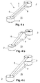
- FIGS. 4a to 4c Possibilities for an inclination of the belt 6 in a slackline device 1 relative to the strut 9 and the footprint 15 are shown schematically.
- an intermediate element 14 can be provided with a specific shape and size, for example, between the strut 9 and the band 6 at a defined position on the strut 9 fixed or slidably on the mounting surface 15, and arranged over which the band is guided.
- the Figure 4c shows another example of the inclination of the belt 6 in a slackline device.
- FIGS. 5a to 5d Basic versions of retaining elements 2 for forming various Slacklinesysteme 16 are shown schematically.
- 16 correspondingly trained holding elements 2 are required for an individual compilation of several, individual Slacklinevorlegizieren 1 to form different types of Slacklinesystems 16 or more Slacklinesysteme 16, depending on their position in the Slacklinesystem 16 one or more recesses 4 and 10.
- the respective holding elements 2 of the slackline devices 1 are finally rigidly connected to each other with respective braces 9 and bands 6, whereby the individually designed slackline systems 16 can be assembled.
- slackline systems 16 are possible in which, for example, inventive slackline devices 1 as a respective basic element in a corresponding number of pieces at a preferably right angle ⁇ to a quadrangle (FIG. FIG. 5c ) or in star form ( FIG. 5d ) or otherwise, both in a linear arrangement as well as with inclinations of bands 6, as described above, are joined together.
- inventive slackline devices 1 as a respective basic element in a corresponding number of pieces at a preferably right angle ⁇ to a quadrangle (FIG. FIG. 5c ) or in star form ( FIG. 5d ) or otherwise, both in a linear arrangement as well as with inclinations of bands 6, as described above, are joined together.
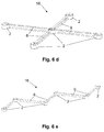
- FIGS. 6a to 6e Examples of the arrangement by means of holding elements 2 according to the FIGS. 5a to 5d formed Slacklinesystemen 16 shown schematically.
- the standing surfaces 5 of the respective holding elements 2 are finally provided with suitable means (not shown) and the length L of the struts 2 and bands 6 is limited to 150cm, for example, whereby a group of the respective slackline devices using children by a supervisor manageable and easily manageable.
- slackline systems 16 can be excluded by different dimensioning of the respective basic elements.
Landscapes
- Health & Medical Sciences (AREA)
- General Health & Medical Sciences (AREA)
- Physical Education & Sports Medicine (AREA)
- Orthopedics, Nursing, And Contraception (AREA)
- Clamps And Clips (AREA)
- Tents Or Canopies (AREA)
Description
- Die Erfindung betrifft eine Slacklinevorrichtung mit wenigstens einem zwischen einem ersten und einem zweiten Halteelement spannbar befestigten Band.
- Die Erfindung ist anwendbar für therapeutische und gymnastische Übungen im Innen- und Außenbereich, wobei das Band zum Balancieren zur Förderung des Gleichgewichts, der Koordination und Konzentration sowie der Körperbeherrschung und außerdem zur Stärkung der Muskulatur ohne zusätzliche Stützelemente und hohen Montageaufwand in kurzer Zeit eingesetzt werden kann.
- Aus der
DE 103 52 292 A1 ist ein Sportgerät bekannt, das ein Fußteil zur Aufstellung auf einem Untergrund aufweist, an dem zumindest ein Paar Stützen mit Abstand zueinander befestigt sind, wobei jede Stütze mit einer Aufnahme zur Befestigung von mindestens einem Seil oder dergleichen zwischen den Stützen versehen ist, wobei zumindest eine der beiden Stützen mit einem Gelenk versehen ist, durch das die Stütze in zwei Endlagen schwenkbar ist. - Aus der
DE 20 2009 002 873 U1 ist zur Befestigung eines Balancierbandes eine Vorrichtung bekannt, die eine auf dem Boden abzustellende Unterkonstruktion und ein von dieser getragenes Fixierelement mit einer Halterung an einem Ende für das Balancierelement und am entgegen gesetzten Ende eine Halterung für ein am Boden zu verankerndes Befestigungsmittel aufweist. - Aus der
DE 298 000 34 U1 ist ein transportables Gerät für komplexe Koordinations- und spezielles Aufbautraining bekannt, das zwei an einem Fußgestell beabstandet zueinander befestigte Stützen aufweist, an denen beabstandet zu dem Fußgestell Halterungen vorgesehen sind, die zur parallelen oder stufenweisen Befestigung von einem Seil oder zwei Seilen oder Bändern einsetzbar sind. - Aus der
DE 20 2011 103 593 U1 ist eine transportable Spann- und Haltevorrichtung für eine Slackline bekannt, bestehend aus einer Tragekonstruktion, einer Halterung für eine Slackline und eine Spannkonstruktion, wobei die Tragekonstruktion aus mindestens zwei im Abstand X zueinander angeordneten Stützkonstruktionen mit im unteren Bereich angeordneten Fußelementen besteht, in den Stützkonstruktionen in verschiedenen Höhen Auflagen für die Slackline angeordnet sind, unterhalb der Horizontalauslegerbefestigung an den Stützkonstruktionen ein den Abstand zwischen den Stützkonstruktionen definierender und die Zugkräfte aufnehmender Zugträger unter der Slacklineanordnung montagefähig befestigt ist und in den Endbereichen des Zugträgers die Befestigungs- und Spannvorrichtung für die Slackline angeordnet sind. - Dokument
AT-A-509194 - Die nach dem Stand der Technik bekannten Einrichtungen weisen den Nachteil auf, dass die Vorrichtungen einerseits kompakt ausgebildet sind und andererseits aus einer Vielzahl sperriger Einzelteile bestehen sowie außerdem zusätzliche Verankerungen erfordern, wodurch ein hohes Sicherheitsrisiko besteht, eine aufwendige Handhabung zu ihrer Aufstellung beziehungsweise Verwendung und entsprechend großflächige Lagermöglichkeiten erforderlich sind.
- Der Erfindung liegt die Aufgabe zu Grunde, eine transportable Slacklinevorrichtung zu schaffen, die eine einfache Montage und Handhabung ermöglicht, die sicher anzuwenden und platzsparend zu lagern ist und die ein universelles Zusammenfügen von einzelnen Vorrichtungen zur Erweiterung des Anwendungsgebiets für den Innen- und Außenbereich ermöglicht.
- Die Aufgabe wird gemäß der Erfindung mit den Merkmalen gemäß dem Patentanspruch 1 gelöst; vorteilhafte Ausgestaltungen der Erfindung sind in den Unteransprüchen 2 bis 10 beschrieben.
- Mit der Erfindung besteht gegenüber den bisherigen Lösungen ein Vorteil darin, dass durch die Verwendung von massiv ausgebildeten Halteelementen für die Slackline sowohl im Innenbereich keine feststehenden Verankerungspunkte, beispielsweise Pfosten zur Netzhalterung für Volleyball oder dergleichen Sportarten, Verankerungen im Fußboden oder an Teilen von Gebäudewandungen wie auch im Außenbereich keine Bäume beziehungsweise andere natürliche Fixpunkte, erforderlich sind.
- Durch die massiven Halteelemente, deren Ausbildung und eine vergleichsweise geringe Bauhöhe ist in Verbindung mit einer entsprechenden Verstrebung in einfacher Weise und platzsparend ein Aufstellen einer erfindungsgemäß gebildeten Slacklinevorrichtung auf einer beliebigen und ebenen Bodenfläche innerhalb eines Gebäudes, aber auch auf beliebigen, ebenen Flächen im Außenbereich, ohne Zusatzverankerungen sicher möglich.
- Beispielsweise kann die Slacklinevorrichtung gemäß der Erfindung bereits frühzeitig sowohl für entsprechende Übungen mit Kindern ab etwa 3 Jahren im Außenbereich oder in Räumen eines Kindergartens wie auch in einer Schule, in Sport- oder Fitnessräumen oder darüber hinaus individuell in geeignetem Wohnraum zu Hause bis zu einer vorgegebenen Belastungsgrenze problemlos und nahezu risikofrei angewendet werden.
- Hierzu sind lediglich jeweils mindestens zwei Halteelemente erforderlich, an denen in der Oberfläche und somit der Höhe der Halteelemente entsprechend, der jeweilige Endabschnitt des Bandes in der axialen Ausnehmung eingesetzt, mit der Spanneinrichtung fixiert und das Band über die Spannkante geführt wird.
- Durch ein mittels der Verstrebung gegenüber dem ersten Haltelement beabstandet angeordnetes zweites Halteelement mit in diesem in gleicher Weise wie beschrieben, eingesetzten anderen Endabschnitt des Bandes und dessen ebenfalls erfolgender Fixierung und Spannung über die jeweilige Spannkante wird das Band als Slackline gespannt und in einer für die Nutzer ungefährlichen Höhe über der Aufstellfläche einsetzbar.
- Ein weiterer Vorteil der erfindungsgemäßen Vorrichtung besteht darin, dass die Slackline auf Grund der möglichen, geringen Bauhöhe der Halteelemente in einer vergleichsweise ebenso geringen und ungefährlichen Höhe über der jeweiligen Aufstellfläche, beispielsweise einem Fußboden, angeordnet ist, wodurch für die Anwender der Vorrichtung die Angst minimiert, die Sicherheit erhöht und das Risiko von Verletzungen durch Stürze und dergleichen erheblich reduziert beziehungsweise vermieden werden.
- Mit der gemäß einer Ausführungsform der Erfindung zusätzlich vorgesehenen Verstellung der Verstrebung in ihrer Längsrichtung besteht ein Vorteil darin, dass das Band beziehungsweise die Slackline jeweiliger Slacklinevorrichtung bei Bedarf und ohne Hilfsmittel problemlos nachgespannt oder entspannt werden kann.
- Die weiterhin vorgesehene Ausgestaltung der Erfindung und der alternative Einsatz des Zwischenelements weist den Vorteil auf, dass das Band der Slackline bei Bedarf definiert in eine Schräge verstellt und dadurch das Balancieren gezielt beeinflusst werden kann.
- Durch die gemäß einer weiteren Ausgestaltung der Erfindung vorgesehene und definierte Anordnung mehrerer Ausnehmungen und Bohrungen in Halteelementen mit jeweiligen Verstrebungen und Bändern besteht ein Vorteil darin, dass mehrere erfindungsgemäß gebildete Slacklinevorrichtungen mit auf einer entsprechend geeigneten Aufstellfläche zu individuell gestaltbaren Systemen zusammenfügbar und aufstellbar sind, wodurch das Anwendungsgebiet, beispielsweise für Gruppenübungen, individuell erheblich erweitert werden kann.
- Die Erfindung wird nachfolgend anhand eines Ausführungsbeispiels und anhand mehrerer Zeichnung näher erläutert; hierbei zeigen:
-
Figur 1 eine schematische Darstellung einer Slacklinevorrichtung gemäß der Erfindung, -
Figur 2 ein Halteelement in einfacher Ausführung, -
Figur 3 eine vereinfachte Darstellung eines Endabschnitts eines Bandes der Slacklinevorrichtung mit einer Spanneinrichtung, -
Figur 4 eine schematische Darstellung einer Slacklinevorrichtung mit einem Zwischenelement zur Bildung einer Schräge für das Band, -
Figuren 5a bis 5d erforderliche Grundausführungen von Halteelementen zur Bildung verschiedener Slacklinesysteme und -
Figuren 6a bis 6e Beispiele von nach denFiguren 5a bis 5d gebildeten Systemanordnungen, schematisch. - In der
Figur 1 ist eine Slacklinevorrichtung gemäß der Erfindung schematisch dargestellt und mit der Position 1 gekennzeichnet. - Die Slacklinevorrichtung 1 weist ein transportables und vorzugsweise zylindrisch ausgebildetes Haltelement 2 mit einer Oberfläche 3 auf, in der zeichnungsgemäß im Randbereich eine vertikal angeordnete Ausnehmung 4 mit einer nicht näher dargestellten Dimensionierung gebildet ist, an der eine gegenüber dem Randbereich beabstandete Spannkante 4.1 vorgesehen ist.
- Das Haltelement 2 ist vorzugsweise zylinderförmig aus Schichtholz in einer nicht näher beschriebenen, vergleichsweise großen Dicke D gebildet, wodurch trotz der Dicke D ein leichtes Handling beziehungsweise eine leichte Montage und auch Transportierbarkeit sowie günstige Lagermöglichkeit erzielt und ein insbesondere für Kinder gesundheitlich unbedenkliches und ferner umweltfreundliches Produkt bereitgestellt wird.
- In der gemäß der
Figur 1 in Verbindung mit derFigur 2 gezeigten Darstellung weist das Halteelement 2 in der axial gegenüber der Oberfläche 3 liegenden Position eine Standfläche 5 auf. - Wie aus den
Figuren 1 und 2 in weiterer Verbindung mit derFigur 3 erkennbar ist, weist die Slacklinevorrichtung 1 ein Band 6 mit nicht näher dargestellten Dimensionen auf, welches an seinem jeweiligen Endabschnitt 7 als Schlaufe ausgebildet ist. - Der Endabschnitt 7 ist zur Aufnahme eines beispielsweise U-förmig ausgebildeten Spannelements 8 vorgesehen, welches mit seinem hier oben liegenden Querabschnitt in dem schlaufenförmigen Endabschnitt 7 eingesetzt und mit diesem gemeinsam in der Ausnehmung 4 lagerichtig eingesetzt ist, sodass sich das Spannelement 8 entsprechend im Endabschnitt 7 des Bandes 6 befindet.
- Durch Einsatz entsprechender Mittel an den Endabschnitten des Spannelements 8 (nicht dargestellt) wird anschließend der jeweilige Endabschnitt 7 des Bandes 6 in der Ausnehmung 4 und zeichnungsgemäß von unten, zunächst im Haltelement 2 fixiert und das Band 6 über der Spannkante 4.1 abgelegt.
- Wie weiter aus der
Figur 1 erkennbar ist, weist die Slacklinevorrichtung 1 eine nicht näher beschriebene, beispielsweise aus Metall gebildete, rohrförmige Verstrebung 9 mit einer festgelegten Länge L und Endabschnitten 9.1 auf. - Die Verstrebung 9 ist in einem entsprechend der Länge L festgelegten Abstand mit einem in gleicher Weise wie das zuvor beschriebene erste Haltelement 2 ausgebildeten, zweiten Haltelement 2 verbunden, wobei die jeweiligen Endabschnitte 9.1 der Verstrebung 9 jeweils in einer in einem Abstand A zeichnungsgemäß senkrecht unterhalb der Spannkante 4.1 im Haltelement 2 radial eingebrachten Ausnehmung 10 festlegbar sind.
- In dem durch die Ausnehmung 10 vorgegebenen Abstand A parallel zu der Verstrebung 9 verlaufend, ist das Band 6 einer der Slacklinevorrichtung 1 entsprechenden Länge mit seinem hier dargestellten, zweiten Endabschnitt 7 mit einem weiteren Spannelement 8 in der in zu dem ersten Halteelement 2 analogen Weise angeordneten Ausnehmung 4 im zweiten Haltelement 2 eingesetzt und festgelegt, sodass das Band 6 an dieser Position ebenfalls mit der Spannkante 4.1 korrespondiert.
- Durch eine exakt abgestimmte Ausbildung der Längen L des Bandes 6 und der Verstrebung 9 kann das Band 6 mittels der Spannelemente 8 in einer festgelegten Spannfestigkeit angeordnet werden und es ist somit als einfache Slacklinevorrichtung 1 für eine Benutzung einsatzfähig.
- Wegen einer eventuellen Ermüdung des Werkstoffs des Bandes 6 und Nachlassen der Spannkraft ist an der Verstrebung 9 im Bereich eines der Endabschnitte 9.1 eine Verstelleinrichtung 11 vorgesehen, die aus einem axial angeordneten Gewindeabschnitt 12 mit einem Verstellmittel 13 gebildet ist.
- Durch ein entsprechendes Verstellen des Verstellmittels 13 entlang des Gewindeabschnitts 12 und beispielsweise gegen das entsprechende Halteelement gerichtet, wird eine Vergrößerung der Länge L beziehungsweise eine Verlängerung der Verstrebung 9 erzielt, wodurch bei Erfordernis in einfacher Weise die Spannkraft des Bandes 6 zur Benutzung wieder hergestellt, erhöht oder andererseits verringert werden kann.
- In den
Figuren 4a bis 4c sind Möglichkeiten für eine Schrägstellung des Bandes 6 in einer Slacklinevorrichtung 1 gegenüber der Verstrebung 9 beziehungsweise der Aufstellfläche 15 schematisch dargestellt. - Während das Band 6 gemäß der
Figur 4a gegenüber der Verstrebung 9 beziehungsweise der Aufstellfläche 15 in annähernd paralleler Lage straff gespannt ist, ist in derFigur 4b eine Möglichkeit für eine Benutzung dargestellt, mit der das Band 6 in einem Abschnitt seiner Länge L schräg gestellt werden kann. - Für diesen Zweck kann ein Zwischenelement 14 mit einer bestimmten Form und Größe vorgesehen werden, das beispielsweise zwischen der Verstrebung 9 und dem Band 6 an einer definierten Position an der Verstrebung 9 fest oder daran oder auf der Aufstellfläche 15 verschiebbar, angeordnet und über welches das Band geführt ist.
- Mit dieser Anordnung wird eine bedarfsweise Schrägstellung des Bandes 6 durch eine entsprechende, lokale und/oder zeitlich begrenzte Änderung des Abstandes A des Bandes 6 gegenüber der Verstrebung 9 beziehungsweise der Aufstellfläche 15 mit gleichen Halteelementen 2 und in der Lage beziehungsweise Höhe ihrer Spannkanten 4.1 ermöglicht.
- Die
Figur 4c zeigt ein weiteres Beispiel zur Schrägstellung des Bandes 6 in einer Slacklinevorrichtung 1. - Hierbei ist beispielsweise die mit der Verstrebung 9 ausgestattete Slacklinevorrichtung 1 ohne das Zwischenelement 14 ausgestattet, dafür jedoch ist eines der beiden Halteelemente 2 durch ein mit diesem in vertikaler Anordnung starr verbundenes, zweites Halteelement 2 erhöht.
- Dadurch ist das Band 6 einerseits an der Spannkante 4.1 (
Figur 1 ) des zeichnungsgemäß unteren Halteelements 2 festgelegt, wohingegen andererseits die Position des Bandes 6 an der Spannkante 4.1 (sieheFigur 1 ) des in einer um die Dicke D eines mit dem hier unten dargestellten Haltelements 2 erhöhten, starr verbundenen weiteren Halteelements 2 festgelegt ist. - In den
Figuren 5a bis 5d sind Grundausführungen von Halteelementen 2 zur Bildung verschiedener Slacklinesysteme 16 schematisch dargestellt. - Wie in den
Figuren 5a bis 5d dargestellt ist, sind für eine individuelle Zusammenstellung von mehreren, einzelnen Slacklinevorrichtungen 1 zur Bildung von verschiedenartigen Figuren eines Slacklinesystems 16 oder mehrerer Slacklinesysteme 16 entsprechend ausgebildete Haltelemente 2 erforderlich, die je nach ihrer Position in dem Slacklinesystem 16 eine oder mehrere Ausnehmungen 4 und 10 aufweisen. - Jeweils nur eine Ausnehmung 4 mit Spannkante 4.1 und eine Ausnehmung 10 sind beispielsweise für Halteelemente 2 erforderlich, die - wie zeichnungsgemäß dargestellt - an den jeweiligen Slacklinevorrichtungen 1 auf der Aufstellfläche 15 im Wesentlichen außen liegend, angeordnet sind und Endpunkte bilden.
- Entsprechend der Art und Größe des zu bildenden Slacklinesystems 16 sind darüber hinaus Halteelemente 2 erforderlich, die zwei oder mehrere und in entsprechendem Winkel versetzt angeordnete Ausnehmungen 4 mit jeweiliger Spannkante 4.1 und Ausnehmungen 10, wie beschrieben, aufweisen und die - wie in den
Figuren 5b und5d dargestellt - beispielsweise in dem Slacklinesystem 16 innen oder mittig liegend, auf einer Aufstellfläche 15 angeordnet sind. - Die jeweiligen Halteelemente 2 der Slacklinevorrichtungen 1 sind schließlich mit jeweiligen Verstrebungen 9 und Bändern 6 starr miteinander verbunden, wodurch die individuell gestalteten Slacklineysteme 16 zusammengestellt werden können.
- Auf diese Weise sind beispielsweise einfache Slacklinesysteme 16 mit in linearer Erstreckung miteinander verbundenen Slacklinevorrichtungen 1 (
Figuren 5a und 5b ) möglich. - Darüber hinaus ist die Erstellung von Slacklinesystemen 16 möglich, bei denen beispielsweise erfindungsgemäße Slacklinevorrichtungen 1 als jeweiliges Grundelement in entsprechender Stückzahl unter einem vorzugsweise rechten Winkel α zu einem Viereck (
Figur 5c ) oder in Sternform (Figur 5d ) oder andersartig, sowohl in linearer Anordnung wie auch mit Schrägstellungen von Bändern 6, wie oben beschrieben, zusammengefügt sind. - In den
Figuren 6a bis 6e sind Beispiele zur Anordnung von mit Hilfe von Halteelementen 2 gemäß denFiguren 5a bis 5d gebildeten Slacklinesystemen 16 schematisch dargestellt. - Für eine rutschfeste Positionierung der einzelnen Slacklinevorrichtungen 1 auf der Aufstellfläche 15 sind schließlich die Standflächen 5 der jeweiligen Haltelemente 2 mit geeigneten Mitteln (nicht dargestellt) versehen und die Länge L der Verstrebungen 2 sowie Bänder 6 ist beispielsweise auf 150cm begrenzt, wodurch beispielsweise eine Gruppe von die jeweiligen Slacklinevorrichtungen benutzenden Kindern von einem Betreuer überschaubar und leicht beherrschbar ist.
- Darüber hinausgehend, kann eine Begrenzung von Slacklinesystemen 16 durch unterschiedliche Dimensionierung der jeweiligen Grundelemente ausgeschlossen werden.
-
- 1
- Slacklinevorrichtung
- 2
- Halteelement
- 3
- Oberfläche
- 4
- Ausnehmung
- 4.1
- Spannkante
- 5
- Standfläche
- 6
- Band
- 7
- Endabschnitt
- 8
- Spannelement
- 9
- Verstrebung
- 9.1
- Endabschnitt der Verstrebung
- 10
- Ausnehmung
- 11
- Verstelleinrichtung
- 12
- Gewindeabschnitt
- 13
- Verstellmittel
- 14
- Zwischenelement
- 15
- Aufstellfläche
- 16
- System von Slacklinevorrichtungen
- A
- Abstand
- D
- Dicke
- L
- Länge
- α
- Winkel
Claims (10)
- Slacklinevorrichtung, aufweisend transportable Halteelemente, ein Band und eine Verstrebung, wobei das Band zwischen den transportablen Halteelementen spannbar und mit seinem jeweiligen Endabschnitt an einem der Haltelemente fixierbar ist, wobei die Halteelemente (2) Massivkörper mit jeweils einer Standfläche (5) und einer Oberfläche (3) sind, die mittels der Verstrebung (9) voneinander beabstandet sind, dadurch gekennzeichnet, dass von der Oberfläche (3) der Halteelemente (2) ausgehend, wenigstens eine axiale Ausnehmung (4) mit einer Spannkante (4.1) in den Halteelementen (2) ausgeformt ist und in der Ausnehmung (4) ein Endabschnitt (7) des Bandes (6) aufgenommen, fixiert und gespannt ist.
- Slacklinevorrichtung nach Anspruch 1, dadurch gekennzeichnet, dass die Halteelemente (2) aus Schichtholz bestehen, wobei die Verstrebung (9) mit ihrem jeweiligen Endabschnitt (9.1) in einer im Haltelement (2) gegenüber der Oberfläche (3) beabstandet angeordneten Ausnehmung (10) in ihrer Lage festgelegt ist.
- Slacklinevorrichtung nach einem der vorstehenden Ansprüche, dadurch gekennzeichnet, dass die Halteelemente (2) die Form eines Zylinders aufweisen.
- Slacklinevorrichtung nach einem der vorstehenden Ansprüche, dadurch gekennzeichnet, dass die Verstrebung (9) rohrförmig ausgebildet ist und in der Ausnehmung (10) der Halteelemente (2) geführt ist.
- Slacklinevorrichtung nach einem der vorstehenden Ansprüche, dadurch gekennzeichnet, dass die Verstrebung (9) mittels einer Verstelleinrichtung (11) axial in der Länge verstellbar ist.
- Slacklinevorrichtung nach einem der vorstehenden Ansprüche, dadurch gekennzeichnet, dass die Verstelleinrichtung (11) einen Gewindeabschnitt (12) aufweist, der zur axialen Verstellung der Verstrebung (9) mit einem drehbaren Verstellmittel (13) verbunden ist.
- Slacklinevorrichtung nach einem der vorstehenden Ansprüche, dadurch gekennzeichnet, dass der jeweilige Endabschnitt (7) des Bandes (6) in der Ausnehmung (4) mit einem Spannelement (8) verbunden und das Band (6) über die Spannkante (4.1) abgewinkelt geführt ist.
- Slacklinevorrichtung nach einem der vorstehenden Ansprüche, dadurch gekennzeichnet, dass das gespannte Band (6) mit einem Zwischenelement (14) gegenüber dem Halteelement (2) höhenverstellbar ist.
- Slacklinevorrichtung nach einem der vorstehenden Ansprüche, dadurch gekennzeichnet, dass Halteelemente (2) vorgesehen sind, die zwei, drei oder vier versetzt voneinander beabstandete Ausnehmungen (4) mit Spannkanten (4.1) und Ausnehmungen (10) aufweisen, wobei entsprechende Halteelemente (2) jeweils mit Bändern (6) und Verstrebungen (9) verspannt und so miteinander verbunden sind, dass auf einer Aufstellfläche (15) die Slacklinevorrichtungen (1) in linearer Erstreckung, in Stern-, Eck- oder in beliebig anderer Form zu einem dementsprechenden System (16) auslegbar beziehungsweise aufstellbar sind.
- Slacklinevorrichtung nach einem der vorstehenden Ansprüche, dadurch gekennzeichnet, dass an der Standfläche (5) Mittel angeordnet sind, die ein Rutschen der Halteelemente (2) verhindern.
Applications Claiming Priority (1)
| Application Number | Priority Date | Filing Date | Title |
|---|---|---|---|
| DE201320105521 DE202013105521U1 (de) | 2013-12-04 | 2013-12-04 | Slacklinevorrichtung |
Publications (2)
| Publication Number | Publication Date |
|---|---|
| EP2886166A1 EP2886166A1 (de) | 2015-06-24 |
| EP2886166B1 true EP2886166B1 (de) | 2016-09-28 |
Family
ID=50097603
Family Applications (1)
| Application Number | Title | Priority Date | Filing Date |
|---|---|---|---|
| EP14154950.1A Active EP2886166B1 (de) | 2013-12-04 | 2014-02-13 | Slacklinevorrichtung |
Country Status (3)
| Country | Link |
|---|---|
| EP (1) | EP2886166B1 (de) |
| DE (1) | DE202013105521U1 (de) |
| DK (1) | DK2886166T3 (de) |
Families Citing this family (3)
| Publication number | Priority date | Publication date | Assignee | Title |
|---|---|---|---|---|
| CN108785971A (zh) * | 2018-06-22 | 2018-11-13 | 黄邓花 | 一种改善心肌和呼吸系统的辅助康复健身器材 |
| CN108785955A (zh) * | 2018-06-22 | 2018-11-13 | 黄邓花 | 一种少儿集体花样皮筋健身康复器械 |
| WO2023039542A1 (en) * | 2021-09-10 | 2023-03-16 | Royal Caribbean Cruises Ltd. | Deployable slackline |
Citations (5)
| Publication number | Priority date | Publication date | Assignee | Title |
|---|---|---|---|---|
| DE29800034U1 (de) | 1998-01-02 | 1998-05-07 | Boukiri, Faouzi, Dipl.-Sportlehrer, 74906 Bad Rappenau | Gerät für komplexes Koordinations- und spezielles Aufbautraining |
| DE10352292A1 (de) | 2002-11-12 | 2004-05-27 | Boukiri, Faouzi | Sportgerät |
| US20080312043A1 (en) | 2007-06-15 | 2008-12-18 | Arnold James Cook | Balance Training and Exercise Device and Method |
| DE202009002873U1 (de) | 2009-03-03 | 2009-06-18 | Bänfer GmbH | Vorrichtung zur Befestigung eines Balancierbandes |
| DE202011103593U1 (de) | 2010-07-23 | 2011-11-21 | Theurin Kg Metallbau | Transportable Spann- und Haltevorrichtung für eine Slackline |
Family Cites Families (4)
| Publication number | Priority date | Publication date | Assignee | Title |
|---|---|---|---|---|
| DE102010000038A1 (de) * | 2010-01-11 | 2010-10-07 | Slackline-Tools GbR (vertretungsberechtigter Gesellschafter: Jörg Helfrich, 78462 Konstanz) | Set für die Installation einer Slackline, insbesondere für Indoor- und Outdooranwendungen |
| AT509194B1 (de) * | 2010-06-14 | 2011-07-15 | Budin Heinz Dipl Ing | Balanciervorrichtung |
| US8986178B2 (en) * | 2010-11-18 | 2015-03-24 | Auburn University | Slackline apparatus and training method |
| DE102011011590B4 (de) * | 2011-02-17 | 2014-08-28 | Gotthilf Benz Turngerätefabrik GmbH + Co. KG | Balanciereinrichtung mit einem Balancierband |
-
2013
- 2013-12-04 DE DE201320105521 patent/DE202013105521U1/de not_active Expired - Lifetime
-
2014
- 2014-02-13 EP EP14154950.1A patent/EP2886166B1/de active Active
- 2014-02-13 DK DK14154950.1T patent/DK2886166T3/en active
Patent Citations (5)
| Publication number | Priority date | Publication date | Assignee | Title |
|---|---|---|---|---|
| DE29800034U1 (de) | 1998-01-02 | 1998-05-07 | Boukiri, Faouzi, Dipl.-Sportlehrer, 74906 Bad Rappenau | Gerät für komplexes Koordinations- und spezielles Aufbautraining |
| DE10352292A1 (de) | 2002-11-12 | 2004-05-27 | Boukiri, Faouzi | Sportgerät |
| US20080312043A1 (en) | 2007-06-15 | 2008-12-18 | Arnold James Cook | Balance Training and Exercise Device and Method |
| DE202009002873U1 (de) | 2009-03-03 | 2009-06-18 | Bänfer GmbH | Vorrichtung zur Befestigung eines Balancierbandes |
| DE202011103593U1 (de) | 2010-07-23 | 2011-11-21 | Theurin Kg Metallbau | Transportable Spann- und Haltevorrichtung für eine Slackline |
Non-Patent Citations (4)
| Title |
|---|
| BRAND 44: "The Slacker's SlackRack", BEDIENUNGSANLEITUNG DES PRODUKTS, 12 August 6014 (6014-08-12), pages 1 - 4, XP055365689, Retrieved from the Internet <URL:http://www.slackersline.com/downloads/SlackRack_Instructions_June_12,2013.pdf> |
| ERZI: "SPORT & AUSSTATTUNG", KATALOG ERZI 2012, 2012, pages 1,2,6 - 17, XP055365687 |
| GONGE: "Physical, cognitive and social. Educational products developing body and mind", PRODUKTKATALOGS GONGE KOLLEKTION 2012/13, 2012, pages 1,3,12 - 14, XP055365691 |
| GONGE: "Slack Line", PRODUKTKATALOGS GONGE 2011, 2011, pages 1,5, XP055365685 |
Also Published As
| Publication number | Publication date |
|---|---|
| DE202013105521U1 (de) | 2014-02-07 |
| EP2886166A1 (de) | 2015-06-24 |
| DK2886166T3 (en) | 2017-01-16 |
Similar Documents
| Publication | Publication Date | Title |
|---|---|---|
| DE202020104198U1 (de) | Baugerüst | |
| DE102010016147B4 (de) | Balanciervorrichtung | |
| DE102014012064B4 (de) | Einrichtung zur winkelvariablen Aufstellung eines Mastes, insbesondere einer Fangstange für den äußeren Blitzschutz | |
| EP2886166A1 (de) | Slacklinevorrichtung | |
| DE202015106331U1 (de) | Transportable Zaunabstützvorrichtung | |
| DE69106781T2 (de) | Modulartige Spielvorrichtung. | |
| EP2548621B1 (de) | Balanciervorrichtung mit einer Tragstruktur | |
| DE102015101788B4 (de) | Sicherheitssystem für den Hochbau und dessen Verwendung | |
| DE202009016734U1 (de) | Vorrichtung zur Befestigung eines Balancierbandes | |
| DE102009009137B4 (de) | Werbebandenelement | |
| DE29904939U1 (de) | Trampolin | |
| EP2654906A1 (de) | Balanceübungsgerät | |
| DE102011050198B4 (de) | Slacklineanordnung, insbesondere für sport- und physiotherapeutische Übungen sowie Mittel für diese Slacklineanordnung | |
| DE102011000321A1 (de) | Ständer für Informationstafel | |
| EP1052345A1 (de) | Vorrichtung zur Sicherung von Öffnungen in Wänden von Gebäuden | |
| EP2312085B1 (de) | Sichtschutzvorrichtung | |
| DE202018102175U1 (de) | Mobile akustische Abschirmeinheit, insbesondere Schallschutzwand | |
| DE202020106736U1 (de) | Absturzsicherung nach Art eines Geländers | |
| DE202008009899U1 (de) | Schutzdach für Trampolin, insbesondere Trampolin mit Sicherheitsnetz | |
| AT13171U1 (de) | Slackline-Montagevorrichtung | |
| DE102005060405A1 (de) | Sportgerät bestehend aus zumindest einem Trampolin sowie eine Baugruppe zum Bestücken des Trampolins | |
| EP3192571B1 (de) | Bauteil für eine haltevorrichtung zum halten wenigstens eines tuches, haltevorrichtung und sportgerät | |
| DE202010008221U1 (de) | Auflage für einen kleinen Sprungkasten sowie ein kleiner Sprungkasten mit einer Auflage für Slacklines | |
| DE202011050064U1 (de) | Slacklineanordnung, insbesondere für sport- und physiotherapeutische Übungen sowie Mittel für diese Slacklineanordnung | |
| DE29918462U1 (de) | Zerlegbares Trampolin |
Legal Events
| Date | Code | Title | Description |
|---|---|---|---|
| PUAI | Public reference made under article 153(3) epc to a published international application that has entered the european phase |
Free format text: ORIGINAL CODE: 0009012 |
|
| 17P | Request for examination filed |
Effective date: 20140213 |
|
| AK | Designated contracting states |
Kind code of ref document: A1 Designated state(s): AL AT BE BG CH CY CZ DE DK EE ES FI FR GB GR HR HU IE IS IT LI LT LU LV MC MK MT NL NO PL PT RO RS SE SI SK SM TR |
|
| AX | Request for extension of the european patent |
Extension state: BA ME |
|
| R17P | Request for examination filed (corrected) |
Effective date: 20150904 |
|
| RBV | Designated contracting states (corrected) |
Designated state(s): AL AT BE BG CH CY CZ DE DK EE ES FI FR GB GR HR HU IE IS IT LI LT LU LV MC MK MT NL NO PL PT RO RS SE SI SK SM TR |
|
| RIC1 | Information provided on ipc code assigned before grant |
Ipc: A63B 7/08 20060101AFI20151211BHEP |
|
| GRAP | Despatch of communication of intention to grant a patent |
Free format text: ORIGINAL CODE: EPIDOSNIGR1 |
|
| INTG | Intention to grant announced |
Effective date: 20160129 |
|
| GRAS | Grant fee paid |
Free format text: ORIGINAL CODE: EPIDOSNIGR3 |
|
| INTG | Intention to grant announced |
Effective date: 20160307 |
|
| RIN1 | Information on inventor provided before grant (corrected) |
Inventor name: MOSCHKE, LARS Inventor name: HOFFMANN, ALEXANDER Inventor name: STUMM, NADJA Inventor name: EICHINGER, HARTMUT |
|
| GRAA | (expected) grant |
Free format text: ORIGINAL CODE: 0009210 |
|
| AK | Designated contracting states |
Kind code of ref document: B1 Designated state(s): AL AT BE BG CH CY CZ DE DK EE ES FI FR GB GR HR HU IE IS IT LI LT LU LV MC MK MT NL NO PL PT RO RS SE SI SK SM TR |
|
| REG | Reference to a national code |
Ref country code: GB Ref legal event code: FG4D Free format text: NOT ENGLISH |
|
| REG | Reference to a national code |
Ref country code: CH Ref legal event code: EP |
|
| REG | Reference to a national code |
Ref country code: AT Ref legal event code: REF Ref document number: 832239 Country of ref document: AT Kind code of ref document: T Effective date: 20161015 |
|
| REG | Reference to a national code |
Ref country code: IE Ref legal event code: FG4D Free format text: LANGUAGE OF EP DOCUMENT: GERMAN |
|
| REG | Reference to a national code |
Ref country code: DE Ref legal event code: R096 Ref document number: 502014001552 Country of ref document: DE |
|
| REG | Reference to a national code |
Ref country code: NL Ref legal event code: FP |
|
| REG | Reference to a national code |
Ref country code: DK Ref legal event code: T3 Effective date: 20170110 |
|
| REG | Reference to a national code |
Ref country code: LT Ref legal event code: MG4D |
|
| PG25 | Lapsed in a contracting state [announced via postgrant information from national office to epo] |
Ref country code: LT Free format text: LAPSE BECAUSE OF FAILURE TO SUBMIT A TRANSLATION OF THE DESCRIPTION OR TO PAY THE FEE WITHIN THE PRESCRIBED TIME-LIMIT Effective date: 20160928 Ref country code: HR Free format text: LAPSE BECAUSE OF FAILURE TO SUBMIT A TRANSLATION OF THE DESCRIPTION OR TO PAY THE FEE WITHIN THE PRESCRIBED TIME-LIMIT Effective date: 20160928 Ref country code: FI Free format text: LAPSE BECAUSE OF FAILURE TO SUBMIT A TRANSLATION OF THE DESCRIPTION OR TO PAY THE FEE WITHIN THE PRESCRIBED TIME-LIMIT Effective date: 20160928 Ref country code: RS Free format text: LAPSE BECAUSE OF FAILURE TO SUBMIT A TRANSLATION OF THE DESCRIPTION OR TO PAY THE FEE WITHIN THE PRESCRIBED TIME-LIMIT Effective date: 20160928 Ref country code: NO Free format text: LAPSE BECAUSE OF FAILURE TO SUBMIT A TRANSLATION OF THE DESCRIPTION OR TO PAY THE FEE WITHIN THE PRESCRIBED TIME-LIMIT Effective date: 20161228 |
|
| REG | Reference to a national code |
Ref country code: FR Ref legal event code: PLFP Year of fee payment: 4 |
|
| PG25 | Lapsed in a contracting state [announced via postgrant information from national office to epo] |
Ref country code: LV Free format text: LAPSE BECAUSE OF FAILURE TO SUBMIT A TRANSLATION OF THE DESCRIPTION OR TO PAY THE FEE WITHIN THE PRESCRIBED TIME-LIMIT Effective date: 20160928 Ref country code: GR Free format text: LAPSE BECAUSE OF FAILURE TO SUBMIT A TRANSLATION OF THE DESCRIPTION OR TO PAY THE FEE WITHIN THE PRESCRIBED TIME-LIMIT Effective date: 20161229 Ref country code: SE Free format text: LAPSE BECAUSE OF FAILURE TO SUBMIT A TRANSLATION OF THE DESCRIPTION OR TO PAY THE FEE WITHIN THE PRESCRIBED TIME-LIMIT Effective date: 20160928 |
|
| REG | Reference to a national code |
Ref country code: DE Ref legal event code: R026 Ref document number: 502014001552 Country of ref document: DE |
|
| PLBI | Opposition filed |
Free format text: ORIGINAL CODE: 0009260 |
|
| 26 | Opposition filed |
Opponent name: WEHRFRITZ GMBH Effective date: 20170320 |
|
| PG25 | Lapsed in a contracting state [announced via postgrant information from national office to epo] |
Ref country code: EE Free format text: LAPSE BECAUSE OF FAILURE TO SUBMIT A TRANSLATION OF THE DESCRIPTION OR TO PAY THE FEE WITHIN THE PRESCRIBED TIME-LIMIT Effective date: 20160928 Ref country code: RO Free format text: LAPSE BECAUSE OF FAILURE TO SUBMIT A TRANSLATION OF THE DESCRIPTION OR TO PAY THE FEE WITHIN THE PRESCRIBED TIME-LIMIT Effective date: 20160928 |
|
| PG25 | Lapsed in a contracting state [announced via postgrant information from national office to epo] |
Ref country code: SM Free format text: LAPSE BECAUSE OF FAILURE TO SUBMIT A TRANSLATION OF THE DESCRIPTION OR TO PAY THE FEE WITHIN THE PRESCRIBED TIME-LIMIT Effective date: 20160928 Ref country code: BE Free format text: LAPSE BECAUSE OF NON-PAYMENT OF DUE FEES Effective date: 20170228 Ref country code: PT Free format text: LAPSE BECAUSE OF FAILURE TO SUBMIT A TRANSLATION OF THE DESCRIPTION OR TO PAY THE FEE WITHIN THE PRESCRIBED TIME-LIMIT Effective date: 20170130 Ref country code: PL Free format text: LAPSE BECAUSE OF FAILURE TO SUBMIT A TRANSLATION OF THE DESCRIPTION OR TO PAY THE FEE WITHIN THE PRESCRIBED TIME-LIMIT Effective date: 20160928 Ref country code: ES Free format text: LAPSE BECAUSE OF FAILURE TO SUBMIT A TRANSLATION OF THE DESCRIPTION OR TO PAY THE FEE WITHIN THE PRESCRIBED TIME-LIMIT Effective date: 20160928 Ref country code: IS Free format text: LAPSE BECAUSE OF FAILURE TO SUBMIT A TRANSLATION OF THE DESCRIPTION OR TO PAY THE FEE WITHIN THE PRESCRIBED TIME-LIMIT Effective date: 20170128 Ref country code: SK Free format text: LAPSE BECAUSE OF FAILURE TO SUBMIT A TRANSLATION OF THE DESCRIPTION OR TO PAY THE FEE WITHIN THE PRESCRIBED TIME-LIMIT Effective date: 20160928 Ref country code: BG Free format text: LAPSE BECAUSE OF FAILURE TO SUBMIT A TRANSLATION OF THE DESCRIPTION OR TO PAY THE FEE WITHIN THE PRESCRIBED TIME-LIMIT Effective date: 20161228 |
|
| PG25 | Lapsed in a contracting state [announced via postgrant information from national office to epo] |
Ref country code: IT Free format text: LAPSE BECAUSE OF FAILURE TO SUBMIT A TRANSLATION OF THE DESCRIPTION OR TO PAY THE FEE WITHIN THE PRESCRIBED TIME-LIMIT Effective date: 20160928 |
|
| PLAX | Notice of opposition and request to file observation + time limit sent |
Free format text: ORIGINAL CODE: EPIDOSNOBS2 |
|
| PG25 | Lapsed in a contracting state [announced via postgrant information from national office to epo] |
Ref country code: MC Free format text: LAPSE BECAUSE OF FAILURE TO SUBMIT A TRANSLATION OF THE DESCRIPTION OR TO PAY THE FEE WITHIN THE PRESCRIBED TIME-LIMIT Effective date: 20160928 |
|
| REG | Reference to a national code |
Ref country code: IE Ref legal event code: MM4A |
|
| PG25 | Lapsed in a contracting state [announced via postgrant information from national office to epo] |
Ref country code: SI Free format text: LAPSE BECAUSE OF FAILURE TO SUBMIT A TRANSLATION OF THE DESCRIPTION OR TO PAY THE FEE WITHIN THE PRESCRIBED TIME-LIMIT Effective date: 20160928 |
|
| PLBB | Reply of patent proprietor to notice(s) of opposition received |
Free format text: ORIGINAL CODE: EPIDOSNOBS3 |
|
| PG25 | Lapsed in a contracting state [announced via postgrant information from national office to epo] |
Ref country code: LU Free format text: LAPSE BECAUSE OF NON-PAYMENT OF DUE FEES Effective date: 20170213 |
|
| REG | Reference to a national code |
Ref country code: BE Ref legal event code: MM Effective date: 20170228 |
|
| REG | Reference to a national code |
Ref country code: FR Ref legal event code: PLFP Year of fee payment: 5 |
|
| PG25 | Lapsed in a contracting state [announced via postgrant information from national office to epo] |
Ref country code: IE Free format text: LAPSE BECAUSE OF NON-PAYMENT OF DUE FEES Effective date: 20170213 |
|
| PG25 | Lapsed in a contracting state [announced via postgrant information from national office to epo] |
Ref country code: MT Free format text: LAPSE BECAUSE OF FAILURE TO SUBMIT A TRANSLATION OF THE DESCRIPTION OR TO PAY THE FEE WITHIN THE PRESCRIBED TIME-LIMIT Effective date: 20160928 |
|
| REG | Reference to a national code |
Ref country code: DE Ref legal event code: R100 Ref document number: 502014001552 Country of ref document: DE |
|
| PG25 | Lapsed in a contracting state [announced via postgrant information from national office to epo] |
Ref country code: AL Free format text: LAPSE BECAUSE OF FAILURE TO SUBMIT A TRANSLATION OF THE DESCRIPTION OR TO PAY THE FEE WITHIN THE PRESCRIBED TIME-LIMIT Effective date: 20160928 |
|
| PLCK | Communication despatched that opposition was rejected |
Free format text: ORIGINAL CODE: EPIDOSNREJ1 |
|
| PLBN | Opposition rejected |
Free format text: ORIGINAL CODE: 0009273 |
|
| STAA | Information on the status of an ep patent application or granted ep patent |
Free format text: STATUS: OPPOSITION REJECTED |
|
| 27O | Opposition rejected |
Effective date: 20181017 |
|
| PG25 | Lapsed in a contracting state [announced via postgrant information from national office to epo] |
Ref country code: HU Free format text: LAPSE BECAUSE OF FAILURE TO SUBMIT A TRANSLATION OF THE DESCRIPTION OR TO PAY THE FEE WITHIN THE PRESCRIBED TIME-LIMIT; INVALID AB INITIO Effective date: 20140213 |
|
| PG25 | Lapsed in a contracting state [announced via postgrant information from national office to epo] |
Ref country code: CY Free format text: LAPSE BECAUSE OF FAILURE TO SUBMIT A TRANSLATION OF THE DESCRIPTION OR TO PAY THE FEE WITHIN THE PRESCRIBED TIME-LIMIT Effective date: 20160928 |
|
| PG25 | Lapsed in a contracting state [announced via postgrant information from national office to epo] |
Ref country code: MK Free format text: LAPSE BECAUSE OF FAILURE TO SUBMIT A TRANSLATION OF THE DESCRIPTION OR TO PAY THE FEE WITHIN THE PRESCRIBED TIME-LIMIT Effective date: 20160928 |
|
| PG25 | Lapsed in a contracting state [announced via postgrant information from national office to epo] |
Ref country code: TR Free format text: LAPSE BECAUSE OF FAILURE TO SUBMIT A TRANSLATION OF THE DESCRIPTION OR TO PAY THE FEE WITHIN THE PRESCRIBED TIME-LIMIT Effective date: 20160928 |
|
| PGFP | Annual fee paid to national office [announced via postgrant information from national office to epo] |
Ref country code: DK Payment date: 20220221 Year of fee payment: 9 Ref country code: CH Payment date: 20220221 Year of fee payment: 9 Ref country code: AT Payment date: 20220215 Year of fee payment: 9 |
|
| PGFP | Annual fee paid to national office [announced via postgrant information from national office to epo] |
Ref country code: CZ Payment date: 20220202 Year of fee payment: 9 |
|
| REG | Reference to a national code |
Ref country code: DK Ref legal event code: EBP Effective date: 20230228 |
|
| REG | Reference to a national code |
Ref country code: CH Ref legal event code: PL |
|
| REG | Reference to a national code |
Ref country code: AT Ref legal event code: MM01 Ref document number: 832239 Country of ref document: AT Kind code of ref document: T Effective date: 20230213 |
|
| PG25 | Lapsed in a contracting state [announced via postgrant information from national office to epo] |
Ref country code: LI Free format text: LAPSE BECAUSE OF NON-PAYMENT OF DUE FEES Effective date: 20230228 Ref country code: CZ Free format text: LAPSE BECAUSE OF NON-PAYMENT OF DUE FEES Effective date: 20230213 Ref country code: CH Free format text: LAPSE BECAUSE OF NON-PAYMENT OF DUE FEES Effective date: 20230228 Ref country code: AT Free format text: LAPSE BECAUSE OF NON-PAYMENT OF DUE FEES Effective date: 20230213 |
|
| PG25 | Lapsed in a contracting state [announced via postgrant information from national office to epo] |
Ref country code: DK Free format text: LAPSE BECAUSE OF NON-PAYMENT OF DUE FEES Effective date: 20230228 |
|
| PGFP | Annual fee paid to national office [announced via postgrant information from national office to epo] |
Ref country code: NL Payment date: 20260218 Year of fee payment: 13 |
|
| PGFP | Annual fee paid to national office [announced via postgrant information from national office to epo] |
Ref country code: GB Payment date: 20260219 Year of fee payment: 13 |
|
| PGFP | Annual fee paid to national office [announced via postgrant information from national office to epo] |
Ref country code: DE Payment date: 20251215 Year of fee payment: 13 |
|
| PGFP | Annual fee paid to national office [announced via postgrant information from national office to epo] |
Ref country code: FR Payment date: 20260223 Year of fee payment: 13 |