EP2886021B2 - Système d'étagère dotée d'une alimentation électrique - Google Patents
Système d'étagère dotée d'une alimentation électrique Download PDFInfo
- Publication number
- EP2886021B2 EP2886021B2 EP14169527.0A EP14169527A EP2886021B2 EP 2886021 B2 EP2886021 B2 EP 2886021B2 EP 14169527 A EP14169527 A EP 14169527A EP 2886021 B2 EP2886021 B2 EP 2886021B2
- Authority
- EP
- European Patent Office
- Prior art keywords
- shelving
- shelf
- current collector
- bracket
- shelving system
- Prior art date
- Legal status (The legal status is an assumption and is not a legal conclusion. Google has not performed a legal analysis and makes no representation as to the accuracy of the status listed.)
- Active
Links
- 230000005611 electricity Effects 0.000 title 1
- 239000004020 conductor Substances 0.000 claims description 81
- 238000010079 rubber tapping Methods 0.000 claims description 23
- 239000000463 material Substances 0.000 claims description 9
- 229910000831 Steel Inorganic materials 0.000 claims description 7
- 239000010959 steel Substances 0.000 claims description 7
- 238000005452 bending Methods 0.000 claims description 3
- 239000007769 metal material Substances 0.000 claims description 3
- 239000011810 insulating material Substances 0.000 description 10
- 239000000725 suspension Substances 0.000 description 8
- IHQKEDIOMGYHEB-UHFFFAOYSA-M sodium dimethylarsinate Chemical class [Na+].C[As](C)([O-])=O IHQKEDIOMGYHEB-UHFFFAOYSA-M 0.000 description 5
- 230000005540 biological transmission Effects 0.000 description 4
- 229910052736 halogen Inorganic materials 0.000 description 4
- 150000002367 halogens Chemical class 0.000 description 4
- 239000012777 electrically insulating material Substances 0.000 description 3
- 238000009434 installation Methods 0.000 description 3
- 239000004033 plastic Substances 0.000 description 3
- 230000002829 reductive effect Effects 0.000 description 3
- 238000006243 chemical reaction Methods 0.000 description 2
- 230000001419 dependent effect Effects 0.000 description 2
- 239000007924 injection Substances 0.000 description 2
- 238000002347 injection Methods 0.000 description 2
- 229910052751 metal Inorganic materials 0.000 description 2
- 239000002184 metal Substances 0.000 description 2
- 230000036961 partial effect Effects 0.000 description 2
- 230000002730 additional effect Effects 0.000 description 1
- 229910052782 aluminium Inorganic materials 0.000 description 1
- XAGFODPZIPBFFR-UHFFFAOYSA-N aluminium Chemical compound [Al] XAGFODPZIPBFFR-UHFFFAOYSA-N 0.000 description 1
- 230000015572 biosynthetic process Effects 0.000 description 1
- 238000005266 casting Methods 0.000 description 1
- 238000010276 construction Methods 0.000 description 1
- 238000006073 displacement reaction Methods 0.000 description 1
- 239000011521 glass Substances 0.000 description 1
- 238000009413 insulation Methods 0.000 description 1
- 230000003993 interaction Effects 0.000 description 1
- 230000002452 interceptive effect Effects 0.000 description 1
- 238000005304 joining Methods 0.000 description 1
- 230000000670 limiting effect Effects 0.000 description 1
- 230000014759 maintenance of location Effects 0.000 description 1
- 238000004519 manufacturing process Methods 0.000 description 1
- 229910001092 metal group alloy Inorganic materials 0.000 description 1
- 238000000034 method Methods 0.000 description 1
- 238000012986 modification Methods 0.000 description 1
- 230000004048 modification Effects 0.000 description 1
- 238000000465 moulding Methods 0.000 description 1
- 230000007935 neutral effect Effects 0.000 description 1
- 230000000737 periodic effect Effects 0.000 description 1
- 238000003825 pressing Methods 0.000 description 1
- 230000008569 process Effects 0.000 description 1
- 230000001681 protective effect Effects 0.000 description 1
- 238000004080 punching Methods 0.000 description 1
- 229910000679 solder Inorganic materials 0.000 description 1
- 238000005476 soldering Methods 0.000 description 1
- 239000007787 solid Substances 0.000 description 1
- 210000002105 tongue Anatomy 0.000 description 1
- 230000007704 transition Effects 0.000 description 1
- 230000000007 visual effect Effects 0.000 description 1
- 239000002023 wood Substances 0.000 description 1
Images


Classifications
-
- A—HUMAN NECESSITIES
- A47—FURNITURE; DOMESTIC ARTICLES OR APPLIANCES; COFFEE MILLS; SPICE MILLS; SUCTION CLEANERS IN GENERAL
- A47F—SPECIAL FURNITURE, FITTINGS, OR ACCESSORIES FOR SHOPS, STOREHOUSES, BARS, RESTAURANTS OR THE LIKE; PAYING COUNTERS
- A47F11/00—Arrangements in shop windows, shop floors or show cases
- A47F11/06—Means for bringing about special optical effects
- A47F11/10—Arrangements of light sources
-
- A—HUMAN NECESSITIES
- A47—FURNITURE; DOMESTIC ARTICLES OR APPLIANCES; COFFEE MILLS; SPICE MILLS; SUCTION CLEANERS IN GENERAL
- A47B—TABLES; DESKS; OFFICE FURNITURE; CABINETS; DRAWERS; GENERAL DETAILS OF FURNITURE
- A47B57/00—Cabinets, racks or shelf units, characterised by features for adjusting shelves or partitions
- A47B57/30—Cabinets, racks or shelf units, characterised by features for adjusting shelves or partitions with means for adjusting the height of detachable shelf supports
- A47B57/40—Cabinets, racks or shelf units, characterised by features for adjusting shelves or partitions with means for adjusting the height of detachable shelf supports consisting of hooks coacting with openings
- A47B57/42—Cabinets, racks or shelf units, characterised by features for adjusting shelves or partitions with means for adjusting the height of detachable shelf supports consisting of hooks coacting with openings the shelf supports being cantilever brackets
-
- A—HUMAN NECESSITIES
- A47—FURNITURE; DOMESTIC ARTICLES OR APPLIANCES; COFFEE MILLS; SPICE MILLS; SUCTION CLEANERS IN GENERAL
- A47F—SPECIAL FURNITURE, FITTINGS, OR ACCESSORIES FOR SHOPS, STOREHOUSES, BARS, RESTAURANTS OR THE LIKE; PAYING COUNTERS
- A47F1/00—Racks for dispensing merchandise; Containers for dispensing merchandise
- A47F1/04—Racks or containers with arrangements for dispensing articles, e.g. by means of gravity or springs
- A47F1/12—Racks or containers with arrangements for dispensing articles, e.g. by means of gravity or springs dispensing from the side of an approximately horizontal stack
-
- A—HUMAN NECESSITIES
- A47—FURNITURE; DOMESTIC ARTICLES OR APPLIANCES; COFFEE MILLS; SPICE MILLS; SUCTION CLEANERS IN GENERAL
- A47F—SPECIAL FURNITURE, FITTINGS, OR ACCESSORIES FOR SHOPS, STOREHOUSES, BARS, RESTAURANTS OR THE LIKE; PAYING COUNTERS
- A47F5/00—Show stands, hangers, or shelves characterised by their constructional features
- A47F5/10—Adjustable or foldable or dismountable display stands
- A47F5/101—Display racks with slotted uprights
- A47F5/103—Display shelving racks with the uprights aligned in only one plane
-
- F—MECHANICAL ENGINEERING; LIGHTING; HEATING; WEAPONS; BLASTING
- F21—LIGHTING
- F21V—FUNCTIONAL FEATURES OR DETAILS OF LIGHTING DEVICES OR SYSTEMS THEREOF; STRUCTURAL COMBINATIONS OF LIGHTING DEVICES WITH OTHER ARTICLES, NOT OTHERWISE PROVIDED FOR
- F21V23/00—Arrangement of electric circuit elements in or on lighting devices
- F21V23/06—Arrangement of electric circuit elements in or on lighting devices the elements being coupling devices, e.g. connectors
-
- F—MECHANICAL ENGINEERING; LIGHTING; HEATING; WEAPONS; BLASTING
- F21—LIGHTING
- F21V—FUNCTIONAL FEATURES OR DETAILS OF LIGHTING DEVICES OR SYSTEMS THEREOF; STRUCTURAL COMBINATIONS OF LIGHTING DEVICES WITH OTHER ARTICLES, NOT OTHERWISE PROVIDED FOR
- F21V33/00—Structural combinations of lighting devices with other articles, not otherwise provided for
- F21V33/0004—Personal or domestic articles
- F21V33/0012—Furniture
- F21V33/002—Racks for compact discs or the like
-
- H—ELECTRICITY
- H02—GENERATION; CONVERSION OR DISTRIBUTION OF ELECTRIC POWER
- H02B—BOARDS, SUBSTATIONS OR SWITCHING ARRANGEMENTS FOR THE SUPPLY OR DISTRIBUTION OF ELECTRIC POWER
- H02B1/00—Frameworks, boards, panels, desks, casings; Details of substations or switching arrangements
- H02B1/20—Bus-bar or other wiring layouts, e.g. in cubicles, in switchyards
-
- A—HUMAN NECESSITIES
- A47—FURNITURE; DOMESTIC ARTICLES OR APPLIANCES; COFFEE MILLS; SPICE MILLS; SUCTION CLEANERS IN GENERAL
- A47B—TABLES; DESKS; OFFICE FURNITURE; CABINETS; DRAWERS; GENERAL DETAILS OF FURNITURE
- A47B2220/00—General furniture construction, e.g. fittings
- A47B2220/0075—Lighting
- A47B2220/0077—Lighting for furniture, e.g. cupboards and racks
-
- A—HUMAN NECESSITIES
- A47—FURNITURE; DOMESTIC ARTICLES OR APPLIANCES; COFFEE MILLS; SPICE MILLS; SUCTION CLEANERS IN GENERAL
- A47B—TABLES; DESKS; OFFICE FURNITURE; CABINETS; DRAWERS; GENERAL DETAILS OF FURNITURE
- A47B2220/00—General furniture construction, e.g. fittings
- A47B2220/0091—Electronic or electric devices
-
- H—ELECTRICITY
- H01—ELECTRIC ELEMENTS
- H01R—ELECTRICALLY-CONDUCTIVE CONNECTIONS; STRUCTURAL ASSOCIATIONS OF A PLURALITY OF MUTUALLY-INSULATED ELECTRICAL CONNECTING ELEMENTS; COUPLING DEVICES; CURRENT COLLECTORS
- H01R25/00—Coupling parts adapted for simultaneous co-operation with two or more identical counterparts, e.g. for distributing energy to two or more circuits
- H01R25/14—Rails or bus-bars constructed so that the counterparts can be connected thereto at any point along their length
- H01R25/147—Low voltage devices, i.e. safe to touch live conductors
-
- H—ELECTRICITY
- H05—ELECTRIC TECHNIQUES NOT OTHERWISE PROVIDED FOR
- H05K—PRINTED CIRCUITS; CASINGS OR CONSTRUCTIONAL DETAILS OF ELECTRIC APPARATUS; MANUFACTURE OF ASSEMBLAGES OF ELECTRICAL COMPONENTS
- H05K7/00—Constructional details common to different types of electric apparatus
- H05K7/14—Mounting supporting structure in casing or on frame or rack
- H05K7/1485—Servers; Data center rooms, e.g. 19-inch computer racks
- H05K7/1488—Cabinets therefor, e.g. chassis or racks or mechanical interfaces between blades and support structures
- H05K7/1489—Cabinets therefor, e.g. chassis or racks or mechanical interfaces between blades and support structures characterized by the mounting of blades therein, e.g. brackets, rails, trays
Definitions
- the present invention relates to a shelving system with at least one shelf rail that is vertical when in use and at least one bracket that can be fixed to the shelf rail in a height-adjustable manner for a support element, in particular a shelf element, with the bracket or the support element being able to carry an electrical device, in particular a lighting device, which is connected to the shelf system is supplied with electrical energy.
- Such shelving systems can be used, for example, for shopfitting to present goods and are known in a variety of embodiments.
- Cantilever shelves are often used, in which shelf brackets designed as angle brackets for carrying shelves or other support elements are cantilevered in shelf rails, which are designed as wall rails or erectable shelf columns or shelf posts and have periodic perforations to accommodate the shelf brackets at different heights.
- the perforations may simply be vertically equally spaced slots.
- the shelf brackets engage the slots with generally hook-shaped engagement portions behind the front surface of the shelf rails, thereby securing the shelf brackets in the desired position.
- the shelf elements are either attached to the top of the shelf brackets or at right angles to these molded support sections.
- Such shelving systems allow easy assembly, disassembly and adjustment of the shelf to the particular needs.
- the shelf elements and the like can be hung quickly and easily at any desired height.
- a lighting device can be mounted, for example, on the front edge or a lateral lower edge of a shelf in order to illuminate the compartment underneath.
- connection cables must be routed from the lighting device to an electrical power supply connection, e.g. a socket. Discreet, unobtrusive routing of the connecting cables is desirable for shelving systems for shopfitting.
- Shelving systems are known from practice, in particular for wall mounting, in which current-carrying rails are integrated into the vertical supports. Most of the time, each support only has a single inner conductor, either for the positive pole or for the negative pole in the case of a DC power supply, so that the shelves can be connected to the two poles in different supports on both sides.
- each shelf rail has an insert with a C-shaped electrically conductive bus bar connected to a single AC power supply terminal.
- a strip-shaped conductor is glued to each angle bracket and extends from a hook-shaped engagement end of the bracket to the opposite end thereof in order to create a connection between the busbar and a connection of the lighting device.
- a circuit thus leads via two busbars in separate shelf rails and via two consoles, each of which is provided with the glued-on conductor strip and carries a shelf.
- the conductor strips glued to the consoles are exposed and can easily touched from the outside, which in store interiors poses an unacceptable risk to staff and customers.
- Shelving systems are also known, in which both conductors of a circuit are integrated in a single shelf rail and, for the connection of a lighting device, socket-type connections are provided at one or more points of the shelf rail, into which plugs or other connectors of the lighting device can be inserted .
- the disadvantage here is that the connections can only be provided at discrete points on a shelf rail, which both limits the adjustability of the shelves in terms of their height and can also impair the aesthetics due to the visible connecting cables and plugs. In addition, easier handling would be desirable.
- WO 2013/087081 A1 discloses a system for electrifying at least one electrical consumer on a piece of furniture with a housing which is designed in the manner of a vertical slotted shelf rail, with a current profile accommodated in the housing, which has two current rails which are arranged parallel to one another and perpendicularly in the current profile, and with a carrier which is designed in the manner of a hanging bracket and can carry a piece of furniture.
- a carrier film made of electrically insulating material is glued to the carrier and carries electrical conductor tracks, each of which is formed from an electrically conductive layer.
- electrically conductive contact surfaces each of which is rigidly attached to an engagement lug and serves to make contact with the busbars in the housing when the engagement lugs are hooked into the housing through respective housing slots.
- a shelf provided with a lighting device in which the power supply lines are hidden in the cavity of the shelf rails are laid, while the brackets for the shelves are combined with the lighting device to form a structural unit and have contact elements that make the conductive connection with the power supply lines when hanging in the shelf rail.
- two busbars provided with contact springs are provided in the shelf rail, which are arranged offset to one another on an insulating plate which is fastened to the rear wall of the shelf rail in the interior.
- the contact elements for the current pick-off are arranged on the end faces of the hook-shaped projections on the console that are used for hanging into the shelf rail.
- the connecting lines leading from the contact elements to the lighting device are routed within the console. This requires specially designed consoles with a complicated and bulky structure.
- shelf rails could be used flexibly for wall mounting or for shelf stands with shelf elements that can be hung on both the front and the back, and if possible without having to pay close attention to the structural position of the shelf rails.
- the shelving system has at least one bracket for a support element, eg a shelf element, which is set up for detachable hanging in one of the slots in the shelf rail.
- the console has at least one e.g Protrudes console at the front of the shelf rail, and an intermediate portion between the engagement portion and the support portion, which is located in the suspended state of the console in the inner passage.
- a current collector device is fixed to the console and has a housing with a current collector section and a connection section connected to the current collector section.
- the current pickup section is arranged on the intermediate section of the bracket and has tapping contacts protruding from the housing for contacting the current conductors of the busbar.
- the connecting section is arranged on the carrier section of the console and is provided for the current-conducting connection of the tapping contacts to a connecting cable of an electrical device.
- the tapping contacts are designed and arranged resiliently to be pushed back when pushed into the inner passage and, when positioned congruently to the current conductors, to be pressed by the spring force against the current conductors in order to establish an electrically conductive connection with them.
- a shelving system should make it possible to easily and quickly adjust the height of the support elements individually and to make the connection for the lighting device or the like quickly and easily.
- the shelf system according to the invention has at least one shelf rail which, when in use, is to be aligned vertically with its longitudinal extent and has at least one front wall and two side walls which delimit an interior space of the shelf rail.
- One or more rows of perforations are provided in the front wall of the shelf rail for mounting support members at different heights, the perforations being spaced apart along the shelf rail and providing access to the interior space.
- a power rail for power supply which runs at least in sections along the shelf rail and has a first and a second electrical conductor which run alongside one another at a distance along one of the side walls of the shelf rail and are insulated from one another.
- the shelving system has at least one bracket for a support element, eg a shelf element, which is set up for detachable hanging in one of the perforations in the shelf rail.
- the console has at least one engagement portion which is set up and arranged to hang the console from the outside through one of the holes to be inserted through the front wall into the interior of the shelf rail in order to be arranged in the interior in the suspended state, and a carrier section for a carrier element connected to the engagement section, which protrudes from the shelf rail in the suspended state of the console.
- a current collector device is fixed to the console and has a housing with a current collector section and a connection section connected to the current collector section.
- the current pickup section is arranged on the engagement section of the bracket and has pick-up contacts protruding from the housing for contacting the current conductors of the busbar.
- the connecting section is arranged on the carrier section of the console and is provided for the current-conducting connection of the tapping contacts to a connecting cable of an electrical device.
- the pick-up contacts are resiliently designed and arranged so that they are pressed into the housing against the spring force when the console is hung in the shelf rail and, after passing through the respective perforation in the interior of the shelf rail behind the front wall, out of the housing by the spring force and onto the first or second conductor of the busbar to be pressed in order to establish an electrically conductive connection with them.
- the shelving system according to the invention is intended in particular for the presentation of goods for shopfitting. It has an extremely simple design and allows easy handling during assembly, disassembly and conversion.
- the consoles are simply hung in the corresponding perforation at the desired height, contacting the inner conductors in the shelf rail being achieved by the tapping contacts of the console according to the invention automatically, i.e. automatically, without requiring any additional actions by the operator.
- a support element for example a shelf element with the lighting device provided on this or another electrical device, can, for example, subsequently or beforehand of the console, with the connecting cable of the lighting device or the like being simply connected in the connection section.
- the shelving system can be easily and quickly converted by simply unhooking the console or consoles of a respective shelf element from the or the associated perforations and hanging in other perforations.
- the circuit for the lighting device or the like is automatically closed.
- the power supply lines for the lighting device or the like are arranged in a single power rail and a single bracket, which, compared to a line arrangement distributed over different shelf rails and brackets, represents a structurally simpler and more cost-effective design and enables simpler connection production.
- the cable lengths and the wiring effort can be significantly reduced.
- the current collectors on the console can be guided in the housing to the outside, essentially invisibly and so that they cannot be touched from the outside.
- the shelving system according to the invention can be designed as a wall shelf with a wall rail set up for mounting on a vertical wall.
- the wall rail can be set up for direct mounting, e.g. by screwing, to the wall or for hanging on a horizontal bar or the like, for example.
- the shelf rail can also form part of a shelf rack designed to be placed on a floor of a room.
- the shelf rail can be a stand tube for setting up on the floor itself or can form a shelf column or support of the shelf frame connected to a stand.
- the shelving system of the invention will generally include at least two shelf rails mounted in a vertical orientation are arranged parallel and next to each other. A shelf element or other support element is then held on two or more shelf rails via respective brackets, with the power supply for a lighting device or the like being provided via only a single shelf rail with an integrated busbar and a single bracket with an integrated current collector device.
- the shelf rail can be formed by any profile rail that has a hollow interior and one or more rows of holes for hanging the brackets on at least one wall or a wall section. It can be round, U-shaped or C-shaped in cross-section.
- the shelf rail is a rectangular tube or profile, which is preferably made of a metallic material, in particular steel.
- the shelf rail then also has a rear wall which runs parallel to and spaced from the front wall between the side walls and has one or more rows of perforations similar or identical to the perforations on the front wall. This means that consoles with support elements can also be arranged in the rear wall.
- shelf rail including the power rail integrated therein, is designed symmetrically with respect to a central plane running perpendicularly through the front wall and the rear wall and symmetrically with respect to a central plane running vertically through the side walls, then there is hardly any need to align the shelf rails when assembling and converting the shelving system to be respected.
- the front wall corresponds to the back wall.
- Different shelving frames can be easily erected with shelf elements that cantilever to the front and rear.
- the perforations are in the form of preferably equidistant slots pass through the respective front wall and optionally the rear wall of the shelf rail and are aligned in the longitudinal direction.
- Such shelf rails with one or two rows of vertical hanging slots can be produced particularly easily and inexpensively.
- the width of the hanging slots is preferably chosen such that it is almost impossible for at least one hand of an adult, preferably also a child's hand, to reach into the hanging slot in order to effectively prevent the conductors in the shelf rail from being touched.
- the slot width can be a maximum of 4-5 mm.
- the height of the slot can be arbitrary and can be, for example, 15 mm, 20 mm or even more.
- the slots can be provided at a distance of, for example, 30 mm, 40 mm, 50 mm or the like from one another, with smaller or larger intervals and non-equidistant slot grids also being possible.
- the power rail integrated in the shelf rail is preferably provided for low-voltage energy supply.
- low voltage is understood to mean, in particular, voltages which do not exceed the limit values for alternating voltage of 50 volts and for direct voltage of 120 volts. In the latter case, the voltages are also preferably less than about 50 volts.
- the usual 6 volt, 12 volt or 24 volt voltages of conventional halogen or LED systems are preferably involved. In this respect, halogen or LED lights form preferred lighting devices or electrical devices that are attached to consoles or shelf elements of the shelving system according to the invention.
- the power rail is set up for low-voltage power supply for direct current and has at least one first power conductor for a first pole, eg a positive conductor, and a second Conductor for a second, different pole, such as a negative conductor on.
- the conductor rail for AC use could have at least one phase conductor and one neutral conductor and, if necessary, also carry a protective conductor.
- the current conductors in the busbar of the shelf rail could also be used only or additionally for data transmission.
- the busbar has a base body made of an electrically insulating material, which has at least one strip assigned to at least one side wall of the shelf rail, in which the first and the second current conductor of the busbar are embedded, preferably in the form of parallel conductor strips and at a distance from one another that they are separated and encompassed by the insulating material.
- the current conductors are then set back in relation to the insulating material that reaches furthest into the interior of the shelf rail.
- the current conductors belonging to a circuit are arranged on the at least one strip of the current rail along a single side wall of the shelf rail, which means that the current conductors are parallel to and at a distance from the associated side wall along the extension of the latter and run towards each other.
- the current conductors can only be slightly spaced from the associated side wall, e.g. only separated by the thickness of the insulating material, or they can also be at a greater distance from the associated side wall of the shelf rail, e.g. also approximately in the middle between this and the opposite side wall or even closer to the latter.
- the conductors are exposed to the side of the opposite side wall and accessible for power tapping from that side.
- the tapping contacts for current tapping are led out laterally on the engagement section of the console.
- a suitable elastically resilient design of the tapping contacts ensures that they touch the current conductor with a high level of contact reliability.
- the main body of the busbar is formed by an H-profile, the width and depth of which are adapted to the width and depth of the interior of the shelf rail, so that the busbar is held relatively immovably in the shelf rail, preferably by frictional locking.
- the H-profile has two parallel strips and a central web connecting the strips. At least a first pair of first and second current conductors is arranged on one of the strips, and at least a second pair of first and second current conductors is arranged on the other strip such that one in each cross-sectional plane is mirror-inverted with respect to a midpoint of the central web. and/or point-symmetrical arrangement is created.
- Such a shelf rail is flexible and easy to use.
- the base body of the busbar has a central body that is essentially in the form of a rectangular tubular profile, which is used for attachment to the shelf rail, and at least one strip that projects from one side of the central body and carries the two or more conductors belonging to a circuit.
- the central body preferably has a width that is adapted to the width of the interior space of the shelf rail, but a significantly smaller depth than the interior space. On the one hand, this allows the busbar to be inserted relatively easily into the shelf rail in the longitudinal direction of the same for assembly, while on the other hand there is a sufficient non-positive connection with it can be maintained in use.
- the strip with the current conductors can be arranged, for example, approximately in the middle of the side of the central body that is assigned to the front wall and can extend outwards, in the assembled state in the direction of the front wall.
- the current conductors are arranged at least on a surface of the strip which is aligned perpendicular to the front wall.
- current conductors for different circuits or data transmission connections can also be arranged on both surfaces of the strip that are opposite the side walls of the shelf rail.
- a further corresponding strip with current conductors is preferably formed on the opposite side of the central body, preferably also in the middle, and is accessible from the rear wall or rear side of the shelf rail.
- the console according to the invention is preferably made as an angle console from a flat, plate-like material, preferably from sheet steel. Other, non-metallic materials are also possible.
- the console preferably has a flat support section which, in use, can be supported with a support edge on the front wall (or rear wall, depending on the arrangement) of the shelf rail, and at least one hook-shaped engagement section which projects on the support edge and is adapted to engage a the associated perforation delimiting wall to embrace like a saddle.
- Such consoles are simple in design and widely used. They can be manufactured inexpensively.
- the current collecting portion of the current collecting device may be arranged on the hook-shaped engaging portion.
- the console can then also only have a single engagement section in the form of a suspension hook.
- the bracket has the first, hook-shaped engagement section and a further engagement section, which protrudes from the support edge at a distance from the first engagement section and encompasses the current collection section of the current collector device.
- the further engagement section with the pick-up contacts of the current collector device can, but does not have to, be in the form of a hanging hook. In any case, it also engages in a perforation to enable additional security on the shelf rail. With two engaging portions, more stable placement and retention of the bracket on the shelf rail is achieved.
- the distance between the engagement sections can correspond to the distance between the holes on the shelf rail or be a multiple thereof.
- the upper engagement section of the console is designed as a hanging hook, while the lower, essentially rectangular engagement section carries the pick-off contacts.
- the bracket can have a support section aligned perpendicularly to the support section.
- the support section can be arranged laterally in a middle area of the console or also on top of the console as a transverse web in order to mount shelves on top of the console.
- the bracket is a stamped part that is manufactured in one piece, the support section being formed from the carrier section by bending and a continuous opening for receiving the housing of the current collector device being stamped out in an engagement section and the carrier section.
- the console can also be manufactured differently, for example by casting, molding, joining and the like.
- the current collector device is arranged in the receiving opening of the console in such a way that the housing protrudes transversely through it and protrudes slightly on both sides of the console.
- the pick-off contacts of the current collector device protrude outwards from one side.
- the pick-up contacts are preferably formed by current collectors spring-mounted in the housing, preferably in the form of wires, which are clamped with one end section in the connecting section of the current collector device, guided to the current pickup section with the formation of multiple bends and led out in a hook-like manner on the current pickup section in order to the pickup contacts to build.
- the resilient mounting can be given in particular by an inherent elasticity of the elastically bendable wires. Round wires are preferably used for the current collectors, but flat wires, contact tongues or the like can also be used. In principle, it would also be possible to use non-elastically bendable contacts and to bias them outwards using suitable spring elements.
- the hook shape of the current collectors at the point where the pick-up contacts are brought out is suitable, e.g. U-, C- or V-shaped, so that when the engaging section of the console is inserted into a hole, the pick-off contacts are loaded transversely through the side wall delimiting the hole and towards the housing are deflected elastically to the extent that they can pass through the side wall of the perforation, with the tapping contacts then springing out again elastically in the interior and coming into contact with the associated conductors.
- the hook shape of the pick-off contacts makes it easier for the console to hang out by pressing the pick-off contacts into the housing in interaction with the side wall of the perforation.
- the housing of the current collector device according to the invention is preferably designed to completely enclose the current collectors except for the pick-off contacts and to protect against contact.
- the housing includes a base part, which comprises the connecting section and the current pickup section and has recesses for receiving the current collectors, eg round wires, and a cover part, which is designed to be attached to the base part.
- the housing can preferably be injection molded from plastic. In any case, it is made of an electrically insulating material.
- the current collection section can have a height that is reduced compared to the height of the hole in order to provide play in the hole that makes it easier to hang up the bracket.
- the width of the current collection section is preferably adapted to the width of the associated engagement section and the hole in order to fit through the hole with little play. However, the width of the current collection section and the engagement section can also be only a fraction of that of the perforation.
- the base part in the region of the connecting section has on one broad side a preferably one-piece closed base plate which closes the base part inaccessible from the outside, while the base part on the other broad side is closed to the outside by the cover part.
- Access to the interior of the housing can be provided at any time via the detachable cover part, for example to solder or connect the connection cable of a lighting device to the current collector.
- the cover part is preferably only arranged in the region of the connecting section in order to design the current pickup section to be sufficiently thin so that it also fits into extremely narrow slotted holes.
- the thickness of the interior The current collection section extending into the shelf rail, which corresponds to the thickness of the base part, is significantly less than the thickness of the connecting section arranged on the bracket outside the shelf rail, which is equal to the sum of the thicknesses of the base part, the base plate and the cover part.
- the current collector device is suitable for any shelf rails with slots or other perforations.
- the thickness of the base plate measured perpendicularly to the broad sides of the connecting section, is smaller than the thickness of the cover part.
- the connection section is designed asymmetrically in the direction perpendicular to the broad sides with respect to a vertical center plane of the base part.
- the shelving system according to the invention also has one or more support elements which are provided on the at least one bracket.
- Different elements such as shelves, baskets, support arms and the like come into consideration as support elements.
- Shelf elements are preferably used on consoles that carry an electrical device, in particular a lighting device, whose connection lines are conductively connected to the tapping contacts in the connecting section of the current collector device. The lighting device or the like is then automatically supplied with power when the console provided with tapping contacts is hooked in. It is sufficient if the shelf element has only a single bracket with an integrated current collector device. A possible second and every further console, all supporting the same shelf element, do not need pantograph devices to exhibit. Similarly, the bus bar need only be present in a single shelf rail and not in the other shelf rail(s) for the same shelf member.
- the shelving system 1 here has three shelf rails 3, which are arranged next to one another in a vertical position and are each attached to the in figure 1 lower end are connected to horizontal rails 4, which serve as feet.
- the vertical shelf rails 3 could also be arranged next to one another other than in a line and could also be supported directly on the floor of the installation room, with fewer or more than three vertical shelf rails 3 being able to be provided.
- the shelf rails 3 could be attached to a vertical wall of a room directly or via a suitable suspension device, for example a horizontal bar.
- the shelf rails 3 are below in connection with the Figures 2a and 2b explained in more detail.
- the shelf frame 2 has several shelf elements 6 which are arranged in a height-adjustable manner on the shelf rails 3 via angle brackets 7 .
- the shelf elements 6 are formed here by plate-shaped supporting elements for the goods to be presented, for example supporting plates made of glass, wood, metal, plastic or some other material. However, the shelf elements 6 do not have to be flat, and alternatively or additionally, others could also be used Support elements, such as baskets, support arms or the like. Be attached to the shelf rails 3 via the brackets 7.
- the shelf elements 6 are only fastened to the shelf rails 3 on one long side via the angle brackets 7 and protrude from the shelf rails 3 in a cantilevered manner. In the present case, shelf elements 6 are both on the in figure 1 the viewer facing the front of the shelf 2 and attached to the rear of the same.
- the side of the shelving system 2 facing the viewer can be referred to as the front 8, while the side facing away from the viewer is referred to as the back 9 and the shelving system 1 also has an in figure 1 left side 11 facing away from the viewer and a right side 12 facing.
- the sides 8 and 9 or 11 and 12 are interchangeable, so that depending on the orientation of the shelving system 1, the back 9 could also form the front 8.
- each shelf element 6 can be seen on the individual shelf elements 6 on the in figure 1 right short side of each shelf element 6 lighting devices 13 are arranged, which serve to illuminate the space below, in particular a shelf element 6 located underneath with goods presented thereon.
- the lighting devices 13 can be, for example, halogen or LED lights and are just one example of different electrical devices that can be provided on the shelf system 1 according to the invention and can be supplied with power via busbars integrated in the shelf rails 3 . This is described in more detail below.
- each shelf rail 3 is formed here by a rectangular tube or profile which (according to the in figure 1 defined directions) a front wall 14, a rear wall 16 and two side walls 17, 18 has.
- the walls 14, 16, 17, 18 define an internal cavity 19 of the shelf rail 3, which has a substantially rectangular cross-section.
- Each shelf rail 3 has a plurality of holes 21 which pass through the front wall 14 in order to provide access to the interior 19 of the shelf rail 3 .
- two rows of perforations 21a, 21b are provided, which are arranged at a small distance next to one another in the illustrated vertical position of use of the shelf rails 3, with each row having a plurality of perforations 21a and 21b, which are arranged at equal distances from one another.
- the perforations 21a, 21b allow the shelf elements 6 or other support elements to be attached at different heights of the shelving system 1 via the angle brackets 7.
- the perforations 21 are designed here in the form of slits, each of which is only a small width, measured in the lateral direction, of about 4-5 mm, preferably at most such a width that a finger of at least an adult person hardly fits into the perforation 21 .
- This is important insofar as at least some of the shelf rails 3 are provided with a busbar 22 for supplying energy to the lighting device 13 or some other electrical device.
- the bus bar 22 is explained in more detail below.
- the slits 21 each have a height of approximately 20 mm and are arranged at a regular spacing of, for example, 30, 40 or 50 mm from one another. It goes without saying that these dimensions are only examples and can vary depending on the requirements.
- the lighting device 13 can be attached to a console 7 or to a support element 6 . As described in more detail below, the lighting device 13 is connected via the console 7 to the conductor rail 22 arranged in the interior 19 of the shelf rail 3 in order to be supplied with electrical energy via this.
- the conductor rail 22 is designed here for low-voltage energy supply, preferably for direct current, and has at least a first conductor 23a, e.g. for a first pole, and a second conductor 24a for a second, different pole of the voltage supply, the conductors 23a, 24a being connected to a circuit belong.
- the busbar 22 has a base body 26 made of an insulating material, in which the first and the second current conductor 23a, 24a are embedded in the form of conductor strips.
- the base body 26 is designed in the form of an H profile and has two mutually parallel strips 27, 28 and a central web 29 connecting the strips.
- the width and depth of the H profile, measured along the width of the central web 29 or along the width of the strips 27, 28, correspond to the width and depth of the interior 19 of the shelf rail 3, in which the busbar 22 is held with little play and cannot be lost can.
- the bus bar 22 is inserted into the shelf rail 3 through an open end thereof.
- the first and second current conductors 23a, 23b are arranged on the strip 27 in parallel and at a distance from one another. They are embedded in the insulating material of the strip 27 in such a way that they are separated from one another by the insulating material 31 and surrounded by protruding lugs 32 of the insulating material. Thus, the surfaces of the current conductors 23a, 24b that are open toward the interior 19 are set back relative to the innermost surface of the insulating material 31, 32, which provides additional protection against accidental contact.
- the unit formed from the shelf rail 3 and the busbar 22 integrated therein is mirror-symmetrical or point-symmetrical here in each cross-sectional plane with respect to a center point 33 of the central web 29 .
- a second pair of a first and a second current conductor 23b, 24b is also provided on the second strip 28 of the conductor rail 22 in the vicinity of the perforations 21a, 21b of the rear wall 16, the current conductors 23b, 24b of the second pair being connected to those 23a, 24a of the first pair are of identical design and are also embedded in the insulating material 31, 32 in such a way that they extend parallel and at a distance from one another and are encompassed by the lugs 32 of the insulating material.
- the angle brackets 7 can be fixed in the front wall 14 and/or the rear wall 16, and a power tap for a lighting device 13 or another electrical device can be made via the respective power conductors 23a, 24a or 23b, 24b.
- shelf rails 3 are preferably made of steel, aluminum or another metal or a metal alloy, while the base body 26 of the busbar 22 can be made of an insulating plastic material and injection molded, for example.
- FIG. 3a is a left console 7a and in Figure 3b a right bracket 7b of the angle brackets 7 figure 1 illustrated in an enlarged perspective view.
- the angle brackets 7a, 7b are substantially similar but are mirror images of each other and are formed from flat, plate-like material, preferably sheet steel. They are preferably manufactured as stamped parts in one piece essentially only by stamping and bending.
- the first console 7a shown essentially has a support section 34 and a first and a second engagement section 36, 37.
- the carrier section 34 is set up here to carry a shelf element 6 .
- the carrier section 34 extends, starting from a support edge 38, which is arranged vertically in use and is optionally supported on the front wall 14 or the rear wall 16 of the shelf rail 3, over a first section 39 of the carrier section 34, which is essentially trapezoidal in side view, and a second Section 41 of the same, which in side view has the shape of an elongated rectangular bar and a reduced height compared to the first section 39, up to a free end 42 opposite the supporting edge 38.
- the second, bar-shaped section 41 is in relation to the flat surface 43 of the support section 34, which is aligned vertically in use, is bent by 90° to form a support section perpendicular to the support section 34, which is aligned horizontally in use and is used for mounting a shelf element 6 or other support element.
- a shelf element 6 can be placed on the support section 44 and by means of fastening screws (not shown here) through fastening holes 46 provided in the support section 44 on the console 7a are fixed.
- the first and second engaging portions 36, 37 each project from the support edge 38 and are intended to engage corresponding overlying holes 21b to secure the bracket 7a to the shelf rail 3.
- the first engagement section 36 which here forms the upper engagement section, is designed in the form of a nose-shaped hook 47 which is directed downwards in the figures and is formed on the supporting edge 38.
- the suspension hook 47 is essentially formed by an area that protrudes backwards from the support edge 38 and is rectangular in side view, which is delimited in the height direction by an upper edge 48 that coincides with the upper edge of the console 7a, and a lower edge 49 that is in the Substantially at the level of the support section 44 and in which a small incision 51 is incorporated, which separates the support edge 38 from a hook tip 52 of the suspension hook 47 that points downwards.
- the hook 47 grips a lower wall delimiting the associated hole 21b in a saddle-like manner, with the wall entering the notch 51.
- the second engagement section 37 could also be designed in the form of a hook.
- it is designed in the form of an extension 53 which is rectangular in side view and which also protrudes from the supporting edge 38 in the rearward direction.
- the extension 53 is arranged at a distance from the hanging hook 47 and also at a distance from a lower edge 54 of the first, trapezoidal section 39 of the carrier section 34, which is dimensioned to match the distance between the perforations 21a, 21b. Its height is less than that of the hanging hook 47 and that of a hole 21a, 21b, in order to enable the bracket 7a to be hung in and hung out of the shelf rail 3.
- the console 7b is essentially similar to the console 7a with a support section 34 having a first, trapezoidal section 39 and a second, strip-shaped section 41, a support section 44 for a shelf element, which is perpendicular to the support section 34, a first engagement section 36 in the form of a hanging hook 47 and a second engagement portion 37 in the form of a substantially rectangular extension 53. To avoid repetition, reference is made to the above description of these sections and the features contained therein.
- the support section is bent in the opposite direction from the flat surface 43 so that a shelf element, eg 6, can be placed between the two brackets 7a, 7b on the support sections 44 and secured to them.
- the console 7b here is designed to accommodate an in Figure 3b Drawn current collector device 56 set up.
- the current pickup device 56 is illustrated here as being attached to the bracket 7b, it could alternatively be attached to the bracket 7a Figure 3a be provided.
- the console 7b for receiving the current collector device 56 has an opening 57 which is produced in the plate-shaped material of the console 7b, leading through it, for example by punching.
- the opening 57 has a first, essentially square opening section 58 and a second opening section 59 which is connected to the first opening section 58 and is essentially rectangular.
- the first opening section is arranged in the first, trapezoidal section 39 of the support section 34 and at a small distance from the lower edge 54 thereof arranged.
- the second opening section 59 extends perpendicularly in the direction of the supporting edge 38 up to the second engagement section 37 and largely into it. With the second opening portion 59, the second engaging portion 37 has the shape of a narrow U-shaped frame.
- the opening 57 with the two sections 58 and 59 is suitably shaped and dimensioned to receive the current collector device 56 .
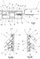
- the current collector device 56 is in greater detail as an assembled assembly in Figures 5a and 5b and with its individual components in the Figures 6a, 6b and 6c shown.
- FIGS 5a and 5b show the current collector device 56 according to the invention in simplified perspective views with a view of different broad sides of the same.
- the current collector device 56 generally has a housing 61 in which current collectors 62, 63, here in the form of elastic, round wires, are arranged, which are used to pick up current on the conductor rail 22 for supplying energy to the lighting device 13 or another electrical device attached to a carrier element .
- the current collectors 62, 63 are on an in Figure 5a left housing section, which is to be referred to here as the current collection section 64, led out in order to form resilient tapping contacts 66, 67 for contacting the current conductors 23, 24 of the busbar 22.
- the current collecting portion 64 is a rectangular portion of the case 61 whose shape and size are adapted to the shape and size of the second opening portion 59 of the opening 57 in the angle bracket 7b.
- the current collector section 64 is accommodated without play in the second opening section 59, with its broad sides 68, 69 having the Complete the broad sides of the console 7b essentially flush.
- the housing 61 of the current collector device 56 also has a connection section 71 which, when in use, is arranged on the support section 34 of the console 7b, in particular in the first square opening section 58 of the opening 57, and is used to connect a connection cable (not shown in detail here). to connect the lighting device 13 or any other electrical device to the current collectors 62, 63.
- the housing 61 is formed here in two parts and has a base part 72, which includes the connecting section 71 and the current pickup section 64 and has recesses for receiving the current collectors 62, 63, and a cover part 73, which is detachably attached to the base part 72.
- Figure 5a shows the current collector device 56 with a view of the cover part 73
- Figure 5b shows the current collector device 56 with a view of a rear or base plate 74, which is arranged on the broad side of the base part 72 facing away from the cover part 73 and closes this there to the outside.
- the base 74 is here and preferably an integral part of the base 72.
- the base 74 has slightly larger dimensions than the remainder of the base 72 such that when the base 72 is positioned in the first opening portion 58 in the console 7b, the base 74 overlaps the edges of the first opening portion 58 slightly. Otherwise, the base is 72 in Figure 6a shown in more detail, with the current collector 62, 62 in the Figures 6b and 6c are shown in more detail.
- the current collectors 62 are formed here by wires 62 that are bent several times, which are round wires here, but could also be formed by flat wires.
- the wires 62, 63 are bent at one end into a U-shape 76, 77 with the U-shaped portion 76 of the first wire 63 being larger than that 77 of the second Wire 64.
- Sections 76, 77 transition into essentially rectilinear sections 78, 79, the ends of which are bent to form U-shaped or V-shaped hooks 81, 82, which form tapping contacts 66, 67.
- the straight section 78 of the first wire 63 is dimensioned somewhat shorter than the straight section 79 of the second wire 64 so that the hooks 81, 82 are arranged next to one another in the current collection section 64 at a distance which corresponds to the distance between the current conductors 23, 24 in the busbar 22 corresponds.
- the wires 63, 64 are housed in the base 72 in recesses adapted to the shape and size of the wires 63, 64 for receiving and guiding them.
- the base part 72 has two larger rectangular recesses 83, 84 for this purpose, which accommodate the ends of the U-shaped sections 76, 77 of the wires 63, 64 and which also accommodate the line ends of a connection cable of the lighting device 13 in order to fix them, e.g. by soldering to connect to the ends of the wires 63,64.
- Insulation displacement terminals or other means could also be provided in the recesses 83, 84 in order to make it easier to connect the connection lines of the lighting devices 13 or another electrical device to the current collectors 62, 63.
- channels 86, 87 are formed in the base part 72, which are adapted to the course of the wires 63, 64, so that they can be accommodated in the channels 86, 87.
- the channels 86, 87 have U-shaped channel sections 88, 89, which receive the U-shaped sections 76, 77 of the wires 63, 64 under clamping, and straight sections 91, 92, which connect to the U-shaped channel sections 88 , 89 and run along the current collecting portion 64 to receive the straight wire portions 78, 79, respectively.
- the straight channel sections 91, 92 in the form of channel openings 93, 94 are lateral led out to the outside, through which the U- or V-hook-shaped tapping contacts 66, 67 protrude out of the base part 72 or housing 61 over the broad side 68 to the outside.
- the current collectors or wires 62, 63 are resiliently mounted in such a way that, when subjected to an external force on the pick-up contacts 66, 67, they can be pressed against the spring force into the base part 72 until they are completely accommodated in the housing 61, being pressed outwards again, out of the base part 72, when the load is relieved by the spring force or inherent elasticity.
- threaded bores 96 are provided in the connecting section 71 of the base part 72 and are used to fasten the cover part 73 to the base part 72 .
- the cover part 73 is a solid cover that is essentially rectangular in plan view and has counter bores 97 aligned with the threaded bores 96 of the base part 72, which enable the cover to be fastened to the broad side of the base part 72 applied from the base plate 74 by means of screw bolts in order to to close the recesses 83, 84, 88, 89 and to clamp the wires 63, 64 in them.
- the edge of the cover part 73 overlaps the edge of the opening 57, which is then clamped between the base plate 74 and the cover part 73.
- the cover part 73 has an elongate connection channel 98 which, as shown in FIG Figure 7b visible, record a connection cable 99 of the lighting device 13 or other electrical device and its lines to the recesses 83, 84 to Connection to the wires 63, 64 can lead.
- the lighting device 13 or any other electrical device can be attached to the console 7b or, for example, to a shelf element 6 either on its short side or long side, depending on your wishes or requirements.
- the busbars 22 are already in the Figures 2a and 2b shown manner have been introduced. It is also assumed that with the shelf rails 3, a shelf frame 2, similar to that in figure 1 , has been constructed, in which two or more shelf rails have been set up on feet 4 at a distance next to one another and have been fixed in their relative position to one another by suitable means that are not illustrated in detail here, such as cross braces or the like. Alternatively, the shelf rails 3 can also be fixed in a vertical position on a vertical wall of a room. It is also assumed that the shelf elements 6 have already been attached to the support sections 44 of the associated brackets 7a, 7b and that a lighting device 13 or another electrical device is mounted on the angle brackets 7b or the shelf elements 6 .
- the shelf units 101 formed in this way can be hung in the desired holes 21a, 21b of two adjacent shelf rails 6.
- the brackets 7a, 7b of a shelf unit 101 are inserted essentially horizontally or slightly obliquely from above into the associated perforations 21b, 21a of a first or second shelf rail 3.
- the tapping contact 67 due to its U- or V-shaped hook shape, is pressed through the wall 102 against the counteracting spring force due to its own elasticity into the channel opening 94.
- the second pick-off contact 67 is pushed into the housing 61 to such an extent that it can pass through the wall 102 when the console 7b is pushed in further, after which it is pushed out again from the channel opening 94 by the spring force.
- the second pick-off contact 67 is then located approximately at the level of the first current conductor 23a.
- the first pick-up contact 66 comes into engagement with the left-hand wall 102 and, due to its U- or V-shaped hook shape, is pushed inward through the wall 102 into the channel opening 93 to such an extent that when the Shelving unit 101 and the first tapping contact 66 can pass through the wall 102 and is then pushed out of the housing 61 in the interior space 19 by the spring force.
- the first and the second tap contact 66 or 67 are opposite the first or second current conductor 23a or 24a (or 23b, 24b) and are sufficiently elastically pressed against them in order to establish a reliable contact.
- the consoles 7a, 7b can then be lowered and in the Figures 7a, 7b 13a and 13a are brought, in which the suspension hook 47 grips around the lower boundary wall 103 of the perforation 21a, which is located in the incision 51, in a saddle-like manner and rests on it.
- the extension 53 forming the second engagement section 37 also rests on the lower boundary wall 103 of the associated hole 21a, while the supporting edge 38 is supported on the front wall 14 or is only slightly spaced from it.
- the lighting device 13 can then be switched on and illuminate the space above or below the shelf element 6 .
- the shelf unit 101 can also be hung in the shelf rail 6 with the lighting device 13 or the like already switched on if the second conductor 24a, 24b, which is arranged deeper in the interior 19 and with which the second tap contact 67 comes into contact last, is connected to the positive pole of the power supply is connected.
- the circuit for the lighting device 13 is then closed by the current collector device 56 according to the invention.
- a shelf unit 101 can also be easily detached and repositioned to a different height.
- the shelf unit 101 is raised somewhat until the lower boundary wall 103 of the perforation 21a leaves the notch 51 and the suspension hook 47 is arranged in alignment with the perforation 21a.
- the shelf element 6 with the brackets 7a, 7b can be pulled out horizontally from the holes 21a, 21b.
- the electrical contact between the pick-up contacts 66, 67 and the current conductors 23a, 24a (or 23b, 24b) is automatically interrupted when they disengage from one another.
- the handling of the shelving system 1 according to the invention is very simple.
- the shelving elements or other support elements are attached and detached in the usual way, with the tapping contacts required for the electrical supply being made or interrupted at the same time.
- the consoles 7a, 7b according to the invention can extremely slim and therefore suitable for shelf rails 3 with very narrow hanging slots.
- the shelving system 1 has simply designed components and can be produced inexpensively.
- FIGS. 5a, 5b and 13b A further advantageous embodiment can be seen in FIGS. 5a, 5b and 13b.
- the thickness of the base plate 74 of the current collector device 56 on the right side of the console 7b in the figures, measured in the transverse direction perpendicular to the surface 43 of the console, is less than the thickness of the cover part 73.
- This small interference contour of the base plate 74 is advantageous in that another bracket 7a of another shelf unit 101 can then be easily inserted into the adjacent perforation 21b of the two-row shelf rail 3 without this being impeded by the current collector device 56 according to the invention.
- the shelf rail 3 can be designed in one or two rows, and the holes 21a, 21b can have different shapes, dimensions and distances from one another.
- the consoles 7a, 7b can also be designed differently, including double-walled.
- Both engagement sections 36, 37 can be designed in the form of hooks which engage behind the respective lower boundary wall 103 of the slot 21. It is also possible to arrange the current collector device 56 on the upper suspension hook 47, with the arrangement on the lower second engagement section 37, particularly if this is not designed as a suspension hook, making handling much easier.
- different free-standing shelving frames can be created or entire shelving walls can be erected.
- the base body 26′ of the conductor rail 22′ has a central body 106 that is essentially in the shape of a rectangular tubular profile, which is used for fastening in the shelf rail 3 and has the sides 109, 111, 112 and 113.
- the base body 26' also has at least one strip 107 which projects from the side 109 of the central body 106 and carries the two or more current conductors 23a, 24a belonging to a circuit.
- the central body 106 preferably has a width that is adapted to the width of the interior space 19 of the shelf rail 3, but a significantly smaller depth than the interior space 19.
- this enables the conductor rail 22′ to be inserted relatively easily into the shelf rail 3 in the longitudinal direction thereof for assembly, while on the other hand a sufficient non-positive connection can be maintained with it during use.
- suitable projections on the base body 26' can be used to provide only narrow-surface or linear contact areas 114, 116, 117 between the base body and the shelf rail 3, which facilitate handling.
- the strip 107 with the current conductors 23a, 24a can be arranged, for example, approximately in the middle of the side 109 of the central body 106 assigned to the front wall 14 and can extend outwards, in the mounted state in the direction of the front wall 14.
- the current conductors 23a, 24a are arranged at least on a surface of the strip which is aligned perpendicularly to the front wall 14.
- current conductors 23a, 24a for different circuits or data transmission connections can also be arranged on both surfaces of the strip 107 which are opposite the side walls 17, 18 of the shelf rail 3.
- another corresponding bar 108 with conductors 23b, 24b is formed on the opposite side 111 of the central body 106, preferably also in the middle, and is accessible from the rear wall or rear side 16 of the shelf rail 3.
- substantially rectangular holes 21 have.
- Two short elevations 119 are provided which run towards one another from the lower wall 103 and the opposite upper wall of each hole 21 and narrow the hole 21 slightly approximately in the middle of its transverse extent.
- An engagement section 36, 37 of a bracket 7 can be accommodated in a partial section of the hole 21 between the elevations 119 and a side wall 118 of the hole 21.
- a shelving system 1, in particular for displaying goods, has at least one vertically aligned shelving rail 3 with a row of spaced-apart vertical slots 21 which lead to an interior space 19 of the shelving rail 3.
- a busbar 22 is arranged for power supply, which has a first and a second conductor 23, 24, which run alongside one another at a distance along one of the side walls 17, 18 of the shelf rail 3 and are insulated from one another.
- the console 7 has at least one engagement section 37 for engaging in one of the slots 21 .
- a current collector device 56 is fastened to the console 7, which has pick-off contacts 66, 67 protruding from a housing 61, which are arranged on the engagement section 37 of the console 7.
Landscapes
- Engineering & Computer Science (AREA)
- General Engineering & Computer Science (AREA)
- Health & Medical Sciences (AREA)
- Public Health (AREA)
- Power Engineering (AREA)
- Arrangement Of Elements, Cooling, Sealing, Or The Like Of Lighting Devices (AREA)
- Warehouses Or Storage Devices (AREA)
Claims (15)
- Système d'étagère, en particulier pour la présentation de marchandises,comprenant au moins un rail d'étagère (3) qui, lors de l'utilisation, doit être orienté verticalement avec sa dimension longitudinale et présente au moins une paroi avant (14) et deux parois latérales (17, 18) qui délimitent un espace interne (19) du rail d'étagère (3), la paroi avant (14) présentant une ou plusieurs rangées de perforations (21) en vue du montage d'éléments supports (6) à des hauteurs différentes, les perforations (21) étant disposées à distance les unes des autres le long du rail d'étagère (3), et créant un accès à l'espace interne (19),comprenant une barre conductrice (22, 22') pour l'alimentation en énergie, qui est intégrée dans l'espace interne (19) du rail d'étagère (3) et s'étend au moins par portions le long du rail d'étagère (3) et présente un premier et un deuxième conducteur (23, 24), qui s'étendent à distance l'un à côté de l'autre, le long de l'une des parois latérales (17, 18) du rail d'étagère (3), et sont isolés l'un vis-à-vis de l'autre ;comprenant au moins une console (7) qui est agencée pour l'accrochage libérable dans l'une des perforations (21) du rail d'étagère (3), la console (7) présentant au moins une portion d'engagement (36, 37) qui, en vue de l'accrochage de la console (7), est agencée et disposée pour être introduite de l'extérieur dans l'espace interne (19) du rail d'étagère (3), à travers l'une des perforations (21) dans la paroi avant (14), afin d'être disposée, à l'état accroché, dans l'espace interne (19), et présentant une portion de support (34) pour un élément support (6), qui, à l'état accroché, dépasse du rail d'étagère (3), etcomprenant un dispositif à balais conducteurs (56) qui est fixé à la console (7) et présente un boîtier (61), doté d'une partie à balais conducteurs (64) qui est disposée sur la portion d'engagement (36, 37) de la console (7) et comporte des contacts de prise (66, 67) destinés à établir le contact avec les conducteurs (23, 24) de la barre conductrice (22), et une partie de liaison (71) qui est disposée sur la portion de support (34) de la console (7) et sert à la liaison des contacts de prise (66, 67) avec un câble de connexion (99) d'un appareil électrique (13),les contacts de prise (66, 67) étant agencés et disposés de façon élastique pour être enfoncés dans le boîtier (61), à l'encontre de la force élastique, lors de l'accrochage de la console (7) dans le rail d'étagère (3), et, après le passage dans l'une des perforations (21), une fois dans l'espace interne (19), derrière la paroi avant (14), être pressés hors du boîtier (61) par la force élastique et contre le premier ou le deuxième conducteur (23, 24), afin d'établir une liaison électriquement conductrice avec ceux-ci.
- Système d'étagère selon la revendication 1, caractérisé en ce que le rail d'étagère (3) est constitué d'un profilé rectangulaire, de préférence en matériau métallique, notamment en acier, et présente en outre une paroi arrière (16) qui s'étend parallèlement à la paroi avant (14) et à distance de celle-ci et présente une ou plusieurs rangées de perforations (21) en vue du montage d'éléments supports (6) à des hauteurs différentes, les perforations (21) étant disposées à distance les unes des autres le long du rail d'étagère (3), et créant un accès à l'espace interne (19), le rail d'étagère (3) étant de préférence réalisé de façon symétrique par rapport à des plans médians s'étendant perpendiculairement à la paroi avant (14) et perpendiculairement aux parois latérales (17, 18).
- Système d'étagère selon l'une des revendications précédentes, caractérisé en ce que les perforations (21) sont réalisées sous forme de fentes (21a, 21b) équidistantes qui traversent 1a paroi (14, 16) respective du rail d'étagère (3), sont orientées dans le sens longitudinal de celui-ci et présentent une largeur qui empêche l'engagement au moins de la main d'un adulte, de préférence également d'une main d'enfant, dans la fente (21a, 21b).
- Système d'étagère selon l'une des revendications précédentes, caractérisé en ce que la barre conductrice (22, 22') est conçue pour l'alimentation en énergie basse tension, de préférence pour du courant continu, et présente au moins un premier conducteur (23a ; 23b) d'une première polarité et un deuxième conducteur (24a ; 24b) d'une deuxième polarité, différente, qui font partie d'un même circuit électrique.
- Système d'étagère selon l'une des revendications précédentes, caractérisé en ce que la barre conductrice (22, 22') présente un corps de base (26, 26') en matériau isolant comportant au moins une aile (27, 28 ; 107, 108) qui est associée à une paroi latérale (17, 18) du rail d'étagère (3) et dans laquelle un premier et un deuxième conducteur (23, 24) s'étendent de préférence sous forme de bandes conductrices, parallèlement et à distance l'un de l'autre, et sont encastrés de manière à ce qu'ils soient chacun entourés par le matériau isolant (31, 32),
- Système d'étagère selon la revendication 5, caractérisé en ce que le corps de base (26) est constitué d'un profilé en H dont la largeur et la profondeur sont adaptées à la largeur et la profondeur de l'espace interne (19) du rail d'étagère (3) et qui présente deux branches (27, 28) mutuellement parallèles et une barre centrale (29) reliant les branches, une première paire formée d'un premier et d'un deuxième conducteur (23a, 24a) étant disposée sur l'une des branches (27), et une deuxième paire formée d'un premier et d'un deuxième conducteur (23b, 24b) étant disposée sur l'autre branche (28), de façon symétrique par rapport à un point médian de la barre centrale (29).
- Système d'étagère selon la revendication 5, caractérisé en ce que le corps de base (26') présente un corps central (106) sensiblement en forme de profilé à tube rectangulaire, qui sert à la fixation dans le rail d'étagère (3), et une aile (107) qui avance, de préférence de façon médiane, à partir d'un côté du corps central (106) associé à la paroi avant (14) et qui porte les conducteurs (23a, 24a), une deuxième aile (108) avec des conducteurs (23b, 24b) étant prévue sur le côté opposé (111) du corps central (106).
- Système d'étagère selon l'une des revendications précédentes, caractérisé en ce que la console (7) est réalisée sous forme de console à équerre dans un matériau plat en forme de plaque, de préférence de 1a tôle d'acier, et présente une portion de support (34) plate qui, lors de l'utilisation, peut s'appuyer avec un bord d'appui (38) sur 1a paroi avant (14) du rail d'étagère (3), ainsi qu'au moins une portion d'engagement (36) sous forme de crochet de suspension (47) qui fait saillie sur le bord d'appui (38) et est agencée pour entourer à la manière d'un étrier une paroi délimitant la perforation (21) associée.
- Système d'étagère selon la revendication 8, caractérisé en ce que la partie à balais conducteurs (64) du dispositif à balais conducteurs (56) est disposée dans le crochet (47).
- Système d'étagère selon la revendication 8, caractérisé en ce que la console (7) présente une première portion d'engagement (36), sous la forme d'un crochet de suspension (47), et une deuxième portion d'engagement (37) qui avance à partir du bord d'appui (38), à distance de la première portion d'engagement (36), et dans laquelle est disposée la partie à balais conducteurs (64) du dispositif à balais conducteurs (56).
- Système d'étagère selon l'une des revendications précédentes, caractérisé en ce que la console (7) présente une partie d'appui (44) qui est orientée perpendiculairement à la portion de support (34) et est prévue pour le montage d'un élément formant tablette (6), la console (7) étant de préférence une pièce découpée, réalisée d'un seul tenant, et la partie d'appui (44) étant façonnée par pliage à partir de la portion de support (34), et une ouverture (57) étant découpée dans une portion d'engagement (36, 37) et dans la portion de support (34), en vue de la réception du boîtier (61) du dispositif à balais conducteurs (56).
- Système d'étagère selon l'une des revendications précédentes, caractérisé en ce que les contacts de prise (66, 67) du dispositif à balais conducteurs (56) sont prévus sur des balais conducteurs (62, 63) montés de façon élastique dans le boîtier (61), de préférence sous forme de fils de section circulaire qui sont fixés dans la partie de liaison (71), sont amenés à la partie à balais conducteurs (64) et sortent en forme de crochets sur la partie à balais conducteurs (64), pour constituer les contacts de prise (66, 67).
- Système d'étagère selon la revendication 12, caractérisé en ce que le boîtier (61) du dispositif à balais conducteurs (56) comprend un élément de base (72), qui comporte la partie de liaison (71) et la partie à balais conducteurs (64) et présente des évidements (83 à 92) pour la réception des balais conducteurs (62, 63), et un élément formant couvercle (73) qui est conçu pour être fixé de manière amovible à l'élément de base (72) et amener un câble de connexion (9) de l'appareil électrique (13) de l'extérieur vers l'intérieur de l'élément de base (72).
- Système d'étagère selon la revendication 13, caractérisé en ce que l'élément de base (72) présente, dans la région de la partie de liaison (71), sur un grand côté, une plaque de base (74) pleine réalisée de préférence d'une seule pièce avec la partie de liaison, et, sur l'autre grand côté, est fermé par l'élément couvercle (73) de façon à ne pas être accessible de l'extérieur, l'épaisseur de 1a plaque de base (74), mesurée perpendiculairement aux grands côtés, étant de préférence inférieure à l'épaisseur de l'élément couvercle (73).
- Système d'étagère selon l'une des revendications précédentes, qui présente en outre au moins un élément tablette (6) qui est fixé à la console (7a, 7b), au nombre d'au moins une, l'élément tablette (6) ou la console (7a, 7b) portant un appareil électrique, notamment un dispositif d'éclairage (13), dont le câble de connexion (99) est relié électriquement aux balais conducteurs (62, 63) dans 1a partie de liaison (71) du dispositif à balais conducteurs (56), l'élément tablette (6) étant de préférence fixé sur un côté à une première console (7b), qui présente le dispositif à balais conducteurs (56), et de l'autre côté à une deuxième console (7a) qui ne présente pas de dispositif à balais conducteurs, et le dispositif à balais conducteurs (56) garantissant le raccordement électrique nécessaire de l'appareil électrique (13) pour faire fonctionner celui-ci.
Priority Applications (3)
| Application Number | Priority Date | Filing Date | Title |
|---|---|---|---|
| PCT/EP2014/078073 WO2015091557A1 (fr) | 2013-12-18 | 2014-12-16 | Système de rayonnages à alimentation électrique |
| CA2933724A CA2933724A1 (fr) | 2013-12-18 | 2014-12-16 | Systeme d'etagere comportant une alimentation d'energie electrique |
| US15/106,138 US9883756B2 (en) | 2013-12-18 | 2014-12-16 | Rack system having an electrical supply |
Applications Claiming Priority (1)
| Application Number | Priority Date | Filing Date | Title |
|---|---|---|---|
| DE102013114289.3A DE102013114289B4 (de) | 2013-12-18 | 2013-12-18 | Regalsystem mit elektrischer Versorgung |
Publications (3)
| Publication Number | Publication Date |
|---|---|
| EP2886021A1 EP2886021A1 (fr) | 2015-06-24 |
| EP2886021B1 EP2886021B1 (fr) | 2017-03-08 |
| EP2886021B2 true EP2886021B2 (fr) | 2023-08-16 |
Family
ID=50842058
Family Applications (1)
| Application Number | Title | Priority Date | Filing Date |
|---|---|---|---|
| EP14169527.0A Active EP2886021B2 (fr) | 2013-12-18 | 2014-05-22 | Système d'étagère dotée d'une alimentation électrique |
Country Status (7)
| Country | Link |
|---|---|
| US (1) | US9883756B2 (fr) |
| EP (1) | EP2886021B2 (fr) |
| CA (1) | CA2933724A1 (fr) |
| DE (1) | DE102013114289B4 (fr) |
| DK (1) | DK2886021T4 (fr) |
| ES (1) | ES2626045T5 (fr) |
| WO (1) | WO2015091557A1 (fr) |
Families Citing this family (52)
| Publication number | Priority date | Publication date | Assignee | Title |
|---|---|---|---|---|
| KR101695696B1 (ko) * | 2015-07-15 | 2017-01-12 | 엘지전자 주식회사 | 냉장고 |
| GB201515029D0 (en) * | 2015-08-24 | 2015-10-07 | Sfd Systems Ltd | Connector system |
| DE202016100561U1 (de) | 2016-02-04 | 2017-05-09 | Dwd Concepts Gmbh | Vorrichtung zur Strom- und/oder Signalübertragung von an einem Regal, insbesondere einem Verkaufsregal anzuordnenden Abnehmern |
| US9831642B2 (en) | 2016-04-25 | 2017-11-28 | Opto International, Inc. | Vertical support for shelving system and shelving system |
| DE102016108323A1 (de) * | 2016-05-04 | 2017-11-09 | Fujitsu Limited | Leitung, Anordnung und Servereinschub |
| CN107524965B (zh) * | 2016-06-22 | 2024-04-05 | 赛尔富电子有限公司 | 一种使用led灯具的货架的取电系统 |
| DE102016113272B4 (de) * | 2016-07-19 | 2021-03-11 | Dwd Concepts Gmbh | Träger für Regalböden mit einem Adapter zum Stromabgriff |
| US10334334B2 (en) * | 2016-07-22 | 2019-06-25 | Intel Corporation | Storage sled and techniques for a data center |
| IT201600082889A1 (it) * | 2016-08-05 | 2018-02-05 | Atelier Archiand Srl | Struttura di espositore |
| PL237463B1 (pl) * | 2016-10-20 | 2021-04-19 | Mago Spolka Akcyjna | Regał ekspozycyjny, zwłaszcza sklepowy |
| DE102016124956A1 (de) * | 2016-12-20 | 2018-06-21 | Rehau Ag + Co | System zur Bestromung mehrerer elektronischer Anzeigeeinrichtungen zur Anzeige von produktbezogenen Informationen und Warenpräsentationssystem |
| CA3048623C (fr) * | 2016-12-30 | 2022-08-30 | Walmart Apollo, Llc | Systeme d'etageres modulaires interchangeables |
| DE102017100958B4 (de) | 2017-01-18 | 2023-06-01 | Juvema Ag | Elektrifizierung für Hänge- und/oder Regalsysteme |
| EP3585215B1 (fr) * | 2017-02-24 | 2021-02-24 | Carrier Corporation | Armoire commerciale réfrigérée |
| DE102017104587A1 (de) * | 2017-03-06 | 2018-09-06 | Dula-Werke Dustmann & Co. Gmbh | Möbel mit wenigstens einer Tragstange |
| DE102017107379A1 (de) * | 2017-04-06 | 2018-10-11 | Grob & Hoffmann GmbH | Beleuchtetes Regalsystem |
| FR3066649B1 (fr) * | 2017-05-17 | 2020-01-24 | Stal Industrie | Dispositif de fixation et de raccordement electrique de supports plans eclairants |
| RU175556U1 (ru) * | 2017-06-22 | 2017-12-08 | Азер Кахраман Оглы Бабаев | Профиль |
| DE202018104213U1 (de) | 2017-08-04 | 2018-11-16 | Bernitz Electronics Gmbh | Vorrichtung zur Strom- und/oder Signalübertragung für an einem Regal befindliche elektronische Auf-/Abnehmer |
| DE202017104685U1 (de) | 2017-08-04 | 2017-10-19 | Bernitz Electronics Gmbh | Vorrichtung zur Strom- und/oder Signalübertragung für an einem Regal befindliche elektronische Auf-/Abnehmer |
| US11253071B2 (en) * | 2017-09-15 | 2022-02-22 | Lego A/S | Shelving system |
| DE202017105793U1 (de) | 2017-09-25 | 2019-01-09 | ITAB Germany GmbH | Regal, insbesondere Warenpräsentationsregal |
| CH714203A1 (de) | 2017-09-29 | 2019-03-29 | Vitra Patente Ag | Einrichtung zur Warenpräsentation und Adapter für eine solche Einrichtung. |
| EP3700391A4 (fr) * | 2017-10-27 | 2021-08-04 | Elfa International AB | Système de stockage mural configurable |
| US11091958B2 (en) * | 2018-01-10 | 2021-08-17 | Sub-Zero Group, Inc. | Shelf electrical signal connector |
| US10851987B2 (en) * | 2018-01-23 | 2020-12-01 | Rangine Corporation | Shelving system with integrated lighting |
| DE202018100713U1 (de) | 2018-02-09 | 2019-05-14 | Rehau Ag + Co | Konsole für einen Regalboden eines Regals und System mit einer derartigen Konsole |
| CA3092642C (fr) | 2018-03-02 | 2023-07-04 | Ergotron, Inc. | Plates-formes reglables en hauteur et mecanismes associes |
| WO2019169355A1 (fr) | 2018-03-02 | 2019-09-06 | Ergotron, Inc. | Plateformes réglables en hauteur et mécanismes associés |
| DE202018101374U1 (de) * | 2018-03-12 | 2019-06-13 | Rehau Ag + Co | Versorgungselement |
| DE102018105699B4 (de) | 2018-03-13 | 2019-10-02 | Juvema Ag | Elektrifizierungssystem für Hänge- und/oder Regalsysteme und Hänge- und/oder Regalsystem mit derartigem Elektrifizierungssystem |
| WO2019219735A1 (fr) * | 2018-05-16 | 2019-11-21 | Signify Holding B.V. | Kit de pièces de piste et de fiche |
| US10939756B2 (en) * | 2018-06-22 | 2021-03-09 | Product Miniature, Inc. | Modular shelf system |
| US10646058B2 (en) * | 2018-07-09 | 2020-05-12 | Vira Insight, Llc | Retail display system with power supply interface |
| US11219320B2 (en) * | 2018-09-07 | 2022-01-11 | Adroit Worldwide Media, Inc. | Electronic shelving systems, cable-managing coupling brackets, and methods thereof |
| US11375812B2 (en) | 2018-09-12 | 2022-07-05 | Elfa International Ab | Wall-mounted, configurable storage system |
| US10939576B2 (en) * | 2018-11-28 | 2021-03-02 | Te Connectivity Corporation | Power connector assembly for a communication system |
| JP6823777B2 (ja) * | 2019-01-30 | 2021-02-03 | 株式会社 ワン・バイ・ワン | コネクタ付支持装置 |
| CN110011236B (zh) * | 2019-03-15 | 2024-02-23 | 浙江建设职业技术学院 | 一种智慧校园管理用服务器集群部署接线装置及装配工艺 |
| JP2020156867A (ja) * | 2019-03-27 | 2020-10-01 | パナソニックIpマネジメント株式会社 | 給電フレームおよび給電フレーム装置 |
| CN110186013A (zh) * | 2019-06-28 | 2019-08-30 | 乐思灯具(上海)有限公司 | 一种照明装置 |
| US11592879B2 (en) * | 2019-07-26 | 2023-02-28 | Artitalia Group Inc. | Modular back panel assembly for a display structure |
| CN110581395B (zh) * | 2019-08-23 | 2024-08-06 | 赛尔富电子有限公司 | 一种嵌入式取电插头、取电托臂以及货架取电系统 |
| DE202019105051U1 (de) * | 2019-09-12 | 2020-12-16 | ARNO GmbH Unternehmen zur Entwicklung & Herstellung von Präsentationssystemen | Theke |
| US11035531B1 (en) * | 2019-10-15 | 2021-06-15 | Sub-Zero Group, Inc. | Shelf light assembly |
| SE543835C2 (en) | 2019-12-23 | 2021-08-10 | Elfa Int Ab | Shelf storage system comprising hang standards with screw holes at distances corresponding to desired bracket to bracket distances |
| SE544025C2 (en) * | 2020-03-04 | 2021-11-09 | Elfa International Ab | Suspension system and glider unit arranged to prevent tilting |
| AU2021264326A1 (en) | 2020-04-30 | 2022-11-24 | Elfa International Ab | Suspension system comprising a rear rail arranged with flanges at least partially extending in different directions and a hangstandard arrangable thereto |
| SE544174C2 (en) | 2020-04-30 | 2022-02-22 | Elfa Int Ab | Hang standard and storage system including the hang standard |
| US11199317B1 (en) * | 2020-08-14 | 2021-12-14 | Scott Fetzer SFEG | Light stick bus system |
| US12068594B2 (en) * | 2021-05-04 | 2024-08-20 | Walmart Apollo, Llc | Adjustable power shelf system |
| AT527009A1 (de) | 2023-02-22 | 2024-09-15 | Ana U Gmbh | Regal-System mit elektrischer Kontaktierung |
Citations (17)
| Publication number | Priority date | Publication date | Assignee | Title |
|---|---|---|---|---|
| US3733755A (en) † | 1971-02-25 | 1973-05-22 | Snaith Inc W | Bracket standard and base rail system |
| CH601930A5 (en) † | 1975-10-08 | 1978-07-14 | Fehlbaum & Co | Hollow profile shelf rail |
| EP0007071A1 (fr) † | 1978-07-06 | 1980-01-23 | Franz Rossmöller | Dispositif de fixation pour suspendre des panneaux ou des éléments de mobilier |
| US4973796A (en) † | 1989-08-10 | 1990-11-27 | Visu-Wall By Hbsa Industries, Inc. | Electrified wall structure |
| US5690415A (en) † | 1995-11-29 | 1997-11-25 | Stylmark, Inc. | Display light |
| EP0974292A2 (fr) † | 1998-07-24 | 2000-01-26 | Umdasch Shop - Concept Gesellschaft m.b.H. | Système d'étagères |
| FR2803995A1 (fr) † | 2000-01-24 | 2001-07-27 | Jean Louis Flon | Tablettes eclairantes deplacables |
| US20020085373A1 (en) † | 1996-04-12 | 2002-07-04 | Powerwall, Inc. | Integrally powered modular furniture |
| WO2005099522A2 (fr) † | 2004-04-19 | 2005-10-27 | Charles Daniel | Systeme de tablette |
| WO2006067396A1 (fr) † | 2004-12-20 | 2006-06-29 | Artform International Limited | Affichage de produit |
| US20060209537A1 (en) † | 2005-03-17 | 2006-09-21 | Stylmark, Inc. | Display assembly with low voltage powered lighting |
| US20080043456A1 (en) † | 2006-08-15 | 2008-02-21 | Bernardini Allen J | Shelf light bracket connector system |
| DE202008001773U1 (de) † | 2008-02-08 | 2008-04-10 | Umdasch Shop Concept Gmbh | Regalsystem, insbesondere zur Präsentation von Waren |
| DE102007028395A1 (de) † | 2007-06-15 | 2008-12-18 | Brinkmann, Wolfgang | Etagenträgersystem |
| WO2012009822A1 (fr) † | 2010-07-21 | 2012-01-26 | Visplay International Ag | Dispositif de suspension pour la présentation de marchandises doté d'un rail profilé et d'un support primaire pouvant être suspendu à l'intérieur |
| DE202012008355U1 (de) † | 2012-09-03 | 2012-10-24 | Visplay International Ag | Aufhängevorriichtung zur Warenpräsentation mit einer stromführenden Profilschiene und darin einhängbarem Primärträger |
| WO2013087081A1 (fr) † | 2011-12-14 | 2013-06-20 | Dula-Werke Dustmann & Co. Gmbh | Dispositif d'alimentation d'un consommateur en énergie électrique et système associé |
Family Cites Families (9)
| Publication number | Priority date | Publication date | Assignee | Title |
|---|---|---|---|---|
| DE3439657A1 (de) | 1984-10-30 | 1986-04-30 | Haberle, Walter, 6368 Bad Vilbel | Mit einer elektrischen beleuchtungseinrichtung versehenes regal |
| US5348485A (en) * | 1993-04-12 | 1994-09-20 | Electronic Retailing Systems Int'l Inc. | Electronic price display system with vertical rail |
| US6109461A (en) * | 1996-07-01 | 2000-08-29 | John Sterling Corporation | Shelf mounting system including mounting brackets having mounting ears for mounting vertical track members to a wall |
| US6364678B1 (en) * | 2000-11-24 | 2002-04-02 | Teknion Furniture Systems Limited | Power column |
| US7338180B2 (en) * | 2005-12-21 | 2008-03-04 | Whirlpool Corporation | Lighted shelf assembly for a refrigerator |
| US20140292168A1 (en) * | 2011-10-24 | 2014-10-02 | Manitowoc Foodservice Companies, Llc | Multiple tier holding display and method |
| US8579127B2 (en) * | 2011-11-01 | 2013-11-12 | Henry V. Dyck | Closet organizer shelving system |
| US20130299439A1 (en) * | 2012-05-09 | 2013-11-14 | Maf Technologies Corporation | Powering Assembly and Method For Adjustable Shelving |
| US20140227893A1 (en) * | 2013-02-14 | 2014-08-14 | L & P Property Management Company | Power-supply device that provides power to a shelving system |
-
2013
- 2013-12-18 DE DE102013114289.3A patent/DE102013114289B4/de active Active
-
2014
- 2014-05-22 DK DK14169527.0T patent/DK2886021T4/da active
- 2014-05-22 ES ES14169527T patent/ES2626045T5/es active Active
- 2014-05-22 EP EP14169527.0A patent/EP2886021B2/fr active Active
- 2014-12-16 WO PCT/EP2014/078073 patent/WO2015091557A1/fr active Application Filing
- 2014-12-16 CA CA2933724A patent/CA2933724A1/fr not_active Abandoned
- 2014-12-16 US US15/106,138 patent/US9883756B2/en active Active
Patent Citations (17)
| Publication number | Priority date | Publication date | Assignee | Title |
|---|---|---|---|---|
| US3733755A (en) † | 1971-02-25 | 1973-05-22 | Snaith Inc W | Bracket standard and base rail system |
| CH601930A5 (en) † | 1975-10-08 | 1978-07-14 | Fehlbaum & Co | Hollow profile shelf rail |
| EP0007071A1 (fr) † | 1978-07-06 | 1980-01-23 | Franz Rossmöller | Dispositif de fixation pour suspendre des panneaux ou des éléments de mobilier |
| US4973796A (en) † | 1989-08-10 | 1990-11-27 | Visu-Wall By Hbsa Industries, Inc. | Electrified wall structure |
| US5690415A (en) † | 1995-11-29 | 1997-11-25 | Stylmark, Inc. | Display light |
| US20020085373A1 (en) † | 1996-04-12 | 2002-07-04 | Powerwall, Inc. | Integrally powered modular furniture |
| EP0974292A2 (fr) † | 1998-07-24 | 2000-01-26 | Umdasch Shop - Concept Gesellschaft m.b.H. | Système d'étagères |
| FR2803995A1 (fr) † | 2000-01-24 | 2001-07-27 | Jean Louis Flon | Tablettes eclairantes deplacables |
| WO2005099522A2 (fr) † | 2004-04-19 | 2005-10-27 | Charles Daniel | Systeme de tablette |
| WO2006067396A1 (fr) † | 2004-12-20 | 2006-06-29 | Artform International Limited | Affichage de produit |
| US20060209537A1 (en) † | 2005-03-17 | 2006-09-21 | Stylmark, Inc. | Display assembly with low voltage powered lighting |
| US20080043456A1 (en) † | 2006-08-15 | 2008-02-21 | Bernardini Allen J | Shelf light bracket connector system |
| DE102007028395A1 (de) † | 2007-06-15 | 2008-12-18 | Brinkmann, Wolfgang | Etagenträgersystem |
| DE202008001773U1 (de) † | 2008-02-08 | 2008-04-10 | Umdasch Shop Concept Gmbh | Regalsystem, insbesondere zur Präsentation von Waren |
| WO2012009822A1 (fr) † | 2010-07-21 | 2012-01-26 | Visplay International Ag | Dispositif de suspension pour la présentation de marchandises doté d'un rail profilé et d'un support primaire pouvant être suspendu à l'intérieur |
| WO2013087081A1 (fr) † | 2011-12-14 | 2013-06-20 | Dula-Werke Dustmann & Co. Gmbh | Dispositif d'alimentation d'un consommateur en énergie électrique et système associé |
| DE202012008355U1 (de) † | 2012-09-03 | 2012-10-24 | Visplay International Ag | Aufhängevorriichtung zur Warenpräsentation mit einer stromführenden Profilschiene und darin einhängbarem Primärträger |
Also Published As
| Publication number | Publication date |
|---|---|
| ES2626045T5 (es) | 2024-04-04 |
| WO2015091557A1 (fr) | 2015-06-25 |
| DE102013114289A1 (de) | 2015-06-18 |
| US20160316939A1 (en) | 2016-11-03 |
| DK2886021T3 (en) | 2017-05-01 |
| DK2886021T4 (da) | 2023-10-23 |
| EP2886021B1 (fr) | 2017-03-08 |
| US9883756B2 (en) | 2018-02-06 |
| ES2626045T3 (es) | 2017-07-21 |
| CA2933724A1 (fr) | 2015-06-25 |
| EP2886021A1 (fr) | 2015-06-24 |
| DE102013114289B4 (de) | 2023-09-07 |
Similar Documents
| Publication | Publication Date | Title |
|---|---|---|
| EP2886021B2 (fr) | Système d'étagère dotée d'une alimentation électrique | |
| EP2170123B1 (fr) | Système de support d'étagère | |
| EP2915215B1 (fr) | Ensemble de modules en série pourvu d'un système de bus d'énergie | |
| DE102013104470B4 (de) | Regalsystem mit Beleuchtung | |
| EP2878051A1 (fr) | Système de montage pour l'agencement d'installations électriques par exemple, notamment dans des armoires de commande | |
| EP2100353B1 (fr) | Dispositif d'armoire de commande | |
| EP2878052A1 (fr) | Système de montage pour l'agencement d'installations électriques par exemple, notamment dans des armoires de commande | |
| EP1994614B1 (fr) | Construction a cadre pour une armoire electrique, armoire electrique et kit pour l'armoire electrique | |
| EP3461376A1 (fr) | Dispositif de présentation de la marchandise et adaptateur pour un tel dispositif | |
| EP2878054B1 (fr) | Système de montage pour par exemple des équipements électriques en particulier dans des armoires électriques | |
| DE102007034600B3 (de) | Montagesystem mit einer Vorrichtung zum Anordnen und Befestigen von elektrischen Einheiten, insbesodere in einem Schaltschrank | |
| DE102015112035A1 (de) | Befestigungsvorrichtung und Regalsystem für die Warenpräsentation | |
| DE202016100561U1 (de) | Vorrichtung zur Strom- und/oder Signalübertragung von an einem Regal, insbesondere einem Verkaufsregal anzuordnenden Abnehmern | |
| EP2878053B1 (fr) | Système d'assemblage pour le montage d'équipements électriques en particulier dans des armoires électriques | |
| DE102010036041B4 (de) | Elektrifizierbares Befestigungssystem | |
| EP1117166A1 (fr) | Dispositif de fixation d'un rail de support sur les montants d'une armoire de commutations | |
| DE4032622C2 (fr) | ||
| EP2084990B1 (fr) | Support de fond de rayonnage et système de réglage | |
| CH713509A2 (de) | Horizontalwarenträger, Präsentationsmodul und Warenpräsentationssystem. | |
| DE102016121435B3 (de) | Elektrifiziertes steckhülsenbasiertes Trägersystem | |
| EP3419128B1 (fr) | Multiprise pour une boîte de distribution | |
| DE2459943C3 (de) | Stromschienenanordnung an Gestellrahmen in Fernmelde-, insbesondere Fernsprechanlagen | |
| DE202010011620U1 (de) | Vorrichtung zum Befestigen und elektrischen Verdrahten einer Vielzahl von elektrischen Einheiten, insbesondere in einem Schaltschrank | |
| DE202018101391U1 (de) | Stromleiteradapter zur Ausbildung einer stromführenden Verbindung mit einer Lochschiene eines Möbelstecksystems | |
| DE102017100958A1 (de) | Elektrifizierung für Hänge- und/oder Regalsysteme |
Legal Events
| Date | Code | Title | Description |
|---|---|---|---|
| PUAI | Public reference made under article 153(3) epc to a published international application that has entered the european phase |
Free format text: ORIGINAL CODE: 0009012 |
|
| 17P | Request for examination filed |
Effective date: 20140522 |
|
| AK | Designated contracting states |
Kind code of ref document: A1 Designated state(s): AL AT BE BG CH CY CZ DE DK EE ES FI FR GB GR HR HU IE IS IT LI LT LU LV MC MK MT NL NO PL PT RO RS SE SI SK SM TR |
|
| AX | Request for extension of the european patent |
Extension state: BA ME |
|
| R17P | Request for examination filed (corrected) |
Effective date: 20150702 |
|
| RBV | Designated contracting states (corrected) |
Designated state(s): AL AT BE BG CH CY CZ DE DK EE ES FI FR GB GR HR HU IE IS IT LI LT LU LV MC MK MT NL NO PL PT RO RS SE SI SK SM TR |
|
| GRAP | Despatch of communication of intention to grant a patent |
Free format text: ORIGINAL CODE: EPIDOSNIGR1 |
|
| INTG | Intention to grant announced |
Effective date: 20160405 |
|
| RIC1 | Information provided on ipc code assigned before grant |
Ipc: A47F 11/10 20060101AFI20160318BHEP Ipc: A47F 5/10 20060101ALI20160318BHEP Ipc: H01R 25/14 20060101ALN20160318BHEP |
|
| GRAP | Despatch of communication of intention to grant a patent |
Free format text: ORIGINAL CODE: EPIDOSNIGR1 |
|
| INTG | Intention to grant announced |
Effective date: 20160722 |
|
| RIC1 | Information provided on ipc code assigned before grant |
Ipc: A47F 11/10 20060101AFI20160713BHEP Ipc: A47F 5/10 20060101ALI20160713BHEP Ipc: H01R 25/14 20060101ALN20160713BHEP |
|
| TPAC | Observations filed by third parties |
Free format text: ORIGINAL CODE: EPIDOSNTIPA |
|
| GRAS | Grant fee paid |
Free format text: ORIGINAL CODE: EPIDOSNIGR3 |
|
| TPAC | Observations filed by third parties |
Free format text: ORIGINAL CODE: EPIDOSNTIPA |
|
| GRAA | (expected) grant |
Free format text: ORIGINAL CODE: 0009210 |
|
| STAA | Information on the status of an ep patent application or granted ep patent |
Free format text: STATUS: THE PATENT HAS BEEN GRANTED |
|
| AK | Designated contracting states |
Kind code of ref document: B1 Designated state(s): AL AT BE BG CH CY CZ DE DK EE ES FI FR GB GR HR HU IE IS IT LI LT LU LV MC MK MT NL NO PL PT RO RS SE SI SK SM TR |
|
| REG | Reference to a national code |
Ref country code: GB Ref legal event code: FG4D Free format text: NOT ENGLISH |
|
| REG | Reference to a national code |
Ref country code: CH Ref legal event code: EP Ref country code: AT Ref legal event code: REF Ref document number: 872746 Country of ref document: AT Kind code of ref document: T Effective date: 20170315 |
|
| REG | Reference to a national code |
Ref country code: DE Ref legal event code: R082 Ref document number: 502014002894 Country of ref document: DE Representative=s name: RUEGER | ABEL PATENT- UND RECHTSANWAELTE, DE Ref country code: DE Ref legal event code: R082 Ref document number: 502014002894 Country of ref document: DE Representative=s name: RUEGER ABEL PATENTANWAELTE PARTGMBB, DE Ref country code: DE Ref legal event code: R082 Ref document number: 502014002894 Country of ref document: DE Representative=s name: RUEGER ABEL PATENT- UND RECHTSANWAELTE, DE Ref country code: DE Ref legal event code: R082 Ref document number: 502014002894 Country of ref document: DE Representative=s name: RUEGER, BARTHELT & ABEL, DE Ref country code: DE Ref legal event code: R081 Ref document number: 502014002894 Country of ref document: DE Owner name: JUVEMA AG, CH Free format text: FORMER OWNER: JUVEMA AG, KREUZLINGEN, CH |
|
| REG | Reference to a national code |
Ref country code: IE Ref legal event code: FG4D Free format text: LANGUAGE OF EP DOCUMENT: GERMAN |
|
| REG | Reference to a national code |
Ref country code: DE Ref legal event code: R096 Ref document number: 502014002894 Country of ref document: DE |
|
| REG | Reference to a national code |
Ref country code: DK Ref legal event code: T3 Effective date: 20170425 |
|
| RAP2 | Party data changed (patent owner data changed or rights of a patent transferred) |
Owner name: JUVEMA AG |
|
| REG | Reference to a national code |
Ref country code: NL Ref legal event code: FP |
|
| REG | Reference to a national code |
Ref country code: FR Ref legal event code: PLFP Year of fee payment: 4 |
|
| REG | Reference to a national code |
Ref country code: LT Ref legal event code: MG4D |
|
| REG | Reference to a national code |
Ref country code: ES Ref legal event code: FG2A Ref document number: 2626045 Country of ref document: ES Kind code of ref document: T3 Effective date: 20170721 |
|
| PG25 | Lapsed in a contracting state [announced via postgrant information from national office to epo] |
Ref country code: NO Free format text: LAPSE BECAUSE OF FAILURE TO SUBMIT A TRANSLATION OF THE DESCRIPTION OR TO PAY THE FEE WITHIN THE PRESCRIBED TIME-LIMIT Effective date: 20170608 Ref country code: LT Free format text: LAPSE BECAUSE OF FAILURE TO SUBMIT A TRANSLATION OF THE DESCRIPTION OR TO PAY THE FEE WITHIN THE PRESCRIBED TIME-LIMIT Effective date: 20170308 Ref country code: GR Free format text: LAPSE BECAUSE OF FAILURE TO SUBMIT A TRANSLATION OF THE DESCRIPTION OR TO PAY THE FEE WITHIN THE PRESCRIBED TIME-LIMIT Effective date: 20170609 Ref country code: FI Free format text: LAPSE BECAUSE OF FAILURE TO SUBMIT A TRANSLATION OF THE DESCRIPTION OR TO PAY THE FEE WITHIN THE PRESCRIBED TIME-LIMIT Effective date: 20170308 Ref country code: HR Free format text: LAPSE BECAUSE OF FAILURE TO SUBMIT A TRANSLATION OF THE DESCRIPTION OR TO PAY THE FEE WITHIN THE PRESCRIBED TIME-LIMIT Effective date: 20170308 |
|
| PG25 | Lapsed in a contracting state [announced via postgrant information from national office to epo] |
Ref country code: BG Free format text: LAPSE BECAUSE OF FAILURE TO SUBMIT A TRANSLATION OF THE DESCRIPTION OR TO PAY THE FEE WITHIN THE PRESCRIBED TIME-LIMIT Effective date: 20170608 Ref country code: LV Free format text: LAPSE BECAUSE OF FAILURE TO SUBMIT A TRANSLATION OF THE DESCRIPTION OR TO PAY THE FEE WITHIN THE PRESCRIBED TIME-LIMIT Effective date: 20170308 Ref country code: RS Free format text: LAPSE BECAUSE OF FAILURE TO SUBMIT A TRANSLATION OF THE DESCRIPTION OR TO PAY THE FEE WITHIN THE PRESCRIBED TIME-LIMIT Effective date: 20170308 Ref country code: SE Free format text: LAPSE BECAUSE OF FAILURE TO SUBMIT A TRANSLATION OF THE DESCRIPTION OR TO PAY THE FEE WITHIN THE PRESCRIBED TIME-LIMIT Effective date: 20170308 |
|
| PG25 | Lapsed in a contracting state [announced via postgrant information from national office to epo] |
Ref country code: SK Free format text: LAPSE BECAUSE OF FAILURE TO SUBMIT A TRANSLATION OF THE DESCRIPTION OR TO PAY THE FEE WITHIN THE PRESCRIBED TIME-LIMIT Effective date: 20170308 Ref country code: EE Free format text: LAPSE BECAUSE OF FAILURE TO SUBMIT A TRANSLATION OF THE DESCRIPTION OR TO PAY THE FEE WITHIN THE PRESCRIBED TIME-LIMIT Effective date: 20170308 Ref country code: CZ Free format text: LAPSE BECAUSE OF FAILURE TO SUBMIT A TRANSLATION OF THE DESCRIPTION OR TO PAY THE FEE WITHIN THE PRESCRIBED TIME-LIMIT Effective date: 20170308 Ref country code: RO Free format text: LAPSE BECAUSE OF FAILURE TO SUBMIT A TRANSLATION OF THE DESCRIPTION OR TO PAY THE FEE WITHIN THE PRESCRIBED TIME-LIMIT Effective date: 20170308 |
|
| REG | Reference to a national code |
Ref country code: DE Ref legal event code: R026 Ref document number: 502014002894 Country of ref document: DE |
|
| PG25 | Lapsed in a contracting state [announced via postgrant information from national office to epo] |
Ref country code: IS Free format text: LAPSE BECAUSE OF FAILURE TO SUBMIT A TRANSLATION OF THE DESCRIPTION OR TO PAY THE FEE WITHIN THE PRESCRIBED TIME-LIMIT Effective date: 20170708 Ref country code: PT Free format text: LAPSE BECAUSE OF FAILURE TO SUBMIT A TRANSLATION OF THE DESCRIPTION OR TO PAY THE FEE WITHIN THE PRESCRIBED TIME-LIMIT Effective date: 20170710 Ref country code: SM Free format text: LAPSE BECAUSE OF FAILURE TO SUBMIT A TRANSLATION OF THE DESCRIPTION OR TO PAY THE FEE WITHIN THE PRESCRIBED TIME-LIMIT Effective date: 20170308 Ref country code: PL Free format text: LAPSE BECAUSE OF FAILURE TO SUBMIT A TRANSLATION OF THE DESCRIPTION OR TO PAY THE FEE WITHIN THE PRESCRIBED TIME-LIMIT Effective date: 20170308 |
|
| PLBI | Opposition filed |
Free format text: ORIGINAL CODE: 0009260 |
|
| PLBI | Opposition filed |
Free format text: ORIGINAL CODE: 0009260 |
|
| PLAX | Notice of opposition and request to file observation + time limit sent |
Free format text: ORIGINAL CODE: EPIDOSNOBS2 |
|
| 26 | Opposition filed |
Opponent name: DWD CONCEPTS GMBH Effective date: 20171128 |
|
| 26 | Opposition filed |
Opponent name: VITRA RETAIL SYSTEMS GMBH Effective date: 20171207 Opponent name: WIELAND ELECTRIC GMBH Effective date: 20171208 |
|
| PG25 | Lapsed in a contracting state [announced via postgrant information from national office to epo] |
Ref country code: MC Free format text: LAPSE BECAUSE OF FAILURE TO SUBMIT A TRANSLATION OF THE DESCRIPTION OR TO PAY THE FEE WITHIN THE PRESCRIBED TIME-LIMIT Effective date: 20170308 |
|
| REG | Reference to a national code |
Ref country code: IE Ref legal event code: MM4A |
|
| PG25 | Lapsed in a contracting state [announced via postgrant information from national office to epo] |
Ref country code: SI Free format text: LAPSE BECAUSE OF FAILURE TO SUBMIT A TRANSLATION OF THE DESCRIPTION OR TO PAY THE FEE WITHIN THE PRESCRIBED TIME-LIMIT Effective date: 20170308 |
|
| PG25 | Lapsed in a contracting state [announced via postgrant information from national office to epo] |
Ref country code: IE Free format text: LAPSE BECAUSE OF NON-PAYMENT OF DUE FEES Effective date: 20170522 |
|
| PLBB | Reply of patent proprietor to notice(s) of opposition received |
Free format text: ORIGINAL CODE: EPIDOSNOBS3 |
|
| REG | Reference to a national code |
Ref country code: FR Ref legal event code: PLFP Year of fee payment: 5 |
|
| PG25 | Lapsed in a contracting state [announced via postgrant information from national office to epo] |
Ref country code: MT Free format text: LAPSE BECAUSE OF FAILURE TO SUBMIT A TRANSLATION OF THE DESCRIPTION OR TO PAY THE FEE WITHIN THE PRESCRIBED TIME-LIMIT Effective date: 20170308 |
|
| RDAF | Communication despatched that patent is revoked |
Free format text: ORIGINAL CODE: EPIDOSNREV1 |
|
| PG25 | Lapsed in a contracting state [announced via postgrant information from national office to epo] |
Ref country code: HU Free format text: LAPSE BECAUSE OF FAILURE TO SUBMIT A TRANSLATION OF THE DESCRIPTION OR TO PAY THE FEE WITHIN THE PRESCRIBED TIME-LIMIT; INVALID AB INITIO Effective date: 20140522 |
|
| APBM | Appeal reference recorded |
Free format text: ORIGINAL CODE: EPIDOSNREFNO |
|
| APBP | Date of receipt of notice of appeal recorded |
Free format text: ORIGINAL CODE: EPIDOSNNOA2O |
|
| APAH | Appeal reference modified |
Free format text: ORIGINAL CODE: EPIDOSCREFNO |
|
| APBQ | Date of receipt of statement of grounds of appeal recorded |
Free format text: ORIGINAL CODE: EPIDOSNNOA3O |
|
| PG25 | Lapsed in a contracting state [announced via postgrant information from national office to epo] |
Ref country code: CY Free format text: LAPSE BECAUSE OF FAILURE TO SUBMIT A TRANSLATION OF THE DESCRIPTION OR TO PAY THE FEE WITHIN THE PRESCRIBED TIME-LIMIT Effective date: 20170308 |
|
| PG25 | Lapsed in a contracting state [announced via postgrant information from national office to epo] |
Ref country code: MK Free format text: LAPSE BECAUSE OF FAILURE TO SUBMIT A TRANSLATION OF THE DESCRIPTION OR TO PAY THE FEE WITHIN THE PRESCRIBED TIME-LIMIT Effective date: 20170308 |
|
| PLAB | Opposition data, opponent's data or that of the opponent's representative modified |
Free format text: ORIGINAL CODE: 0009299OPPO |
|
| R26 | Opposition filed (corrected) |
Opponent name: VITRA RETAIL SYSTEMS GMBH Effective date: 20171207 |
|
| APAH | Appeal reference modified |
Free format text: ORIGINAL CODE: EPIDOSCREFNO |
|
| PG25 | Lapsed in a contracting state [announced via postgrant information from national office to epo] |
Ref country code: TR Free format text: LAPSE BECAUSE OF FAILURE TO SUBMIT A TRANSLATION OF THE DESCRIPTION OR TO PAY THE FEE WITHIN THE PRESCRIBED TIME-LIMIT Effective date: 20170308 |
|
| PG25 | Lapsed in a contracting state [announced via postgrant information from national office to epo] |
Ref country code: AL Free format text: LAPSE BECAUSE OF FAILURE TO SUBMIT A TRANSLATION OF THE DESCRIPTION OR TO PAY THE FEE WITHIN THE PRESCRIBED TIME-LIMIT Effective date: 20170308 |
|
| APBU | Appeal procedure closed |
Free format text: ORIGINAL CODE: EPIDOSNNOA9O |
|
| REG | Reference to a national code |
Ref country code: FR Ref legal event code: PLFP Year of fee payment: 9 |
|
| PUAH | Patent maintained in amended form |
Free format text: ORIGINAL CODE: 0009272 |
|
| STAA | Information on the status of an ep patent application or granted ep patent |
Free format text: STATUS: PATENT MAINTAINED AS AMENDED |
|
| PGFP | Annual fee paid to national office [announced via postgrant information from national office to epo] |
Ref country code: DE Payment date: 20230626 Year of fee payment: 10 |
|
| 27A | Patent maintained in amended form |
Effective date: 20230816 |
|
| AK | Designated contracting states |
Kind code of ref document: B2 Designated state(s): AL AT BE BG CH CY CZ DE DK EE ES FI FR GB GR HR HU IE IS IT LI LT LU LV MC MK MT NL NO PL PT RO RS SE SI SK SM TR |
|
| REG | Reference to a national code |
Ref country code: DE Ref legal event code: R102 Ref document number: 502014002894 Country of ref document: DE |
|
| REG | Reference to a national code |
Ref country code: DK Ref legal event code: T4 Effective date: 20231018 |
|
| PGFP | Annual fee paid to national office [announced via postgrant information from national office to epo] |
Ref country code: IT Payment date: 20230630 Year of fee payment: 10 Ref country code: ES Payment date: 20230725 Year of fee payment: 10 Ref country code: CH Payment date: 20230719 Year of fee payment: 10 |
|
| REG | Reference to a national code |
Ref country code: NL Ref legal event code: FP |
|
| REG | Reference to a national code |
Ref country code: ES Ref legal event code: DC2A Ref document number: 2626045 Country of ref document: ES Kind code of ref document: T5 Effective date: 20240404 |
|
| PGFP | Annual fee paid to national office [announced via postgrant information from national office to epo] |
Ref country code: LU Payment date: 20240530 Year of fee payment: 11 |
|
| PGFP | Annual fee paid to national office [announced via postgrant information from national office to epo] |
Ref country code: NL Payment date: 20240527 Year of fee payment: 11 |
|
| PGFP | Annual fee paid to national office [announced via postgrant information from national office to epo] |
Ref country code: GB Payment date: 20240620 Year of fee payment: 11 |
|
| PGFP | Annual fee paid to national office [announced via postgrant information from national office to epo] |
Ref country code: DK Payment date: 20240530 Year of fee payment: 11 |
|
| PGFP | Annual fee paid to national office [announced via postgrant information from national office to epo] |
Ref country code: AT Payment date: 20240528 Year of fee payment: 11 |
|
| PGFP | Annual fee paid to national office [announced via postgrant information from national office to epo] |
Ref country code: FR Payment date: 20240527 Year of fee payment: 11 |
|
| PGFP | Annual fee paid to national office [announced via postgrant information from national office to epo] |
Ref country code: BE Payment date: 20240527 Year of fee payment: 11 |