EP2880232B2 - Kraftfahrzeugschlossanordnung - Google Patents
Kraftfahrzeugschlossanordnung Download PDFInfo
- Publication number
- EP2880232B2 EP2880232B2 EP13742222.6A EP13742222A EP2880232B2 EP 2880232 B2 EP2880232 B2 EP 2880232B2 EP 13742222 A EP13742222 A EP 13742222A EP 2880232 B2 EP2880232 B2 EP 2880232B2
- Authority
- EP
- European Patent Office
- Prior art keywords
- actuating lever
- lever
- clutch arrangement
- pawl
- arrangement
- Prior art date
- Legal status (The legal status is an assumption and is not a legal conclusion. Google has not performed a legal analysis and makes no representation as to the accuracy of the status listed.)
- Active
Links
Images
Classifications
-
- E—FIXED CONSTRUCTIONS
- E05—LOCKS; KEYS; WINDOW OR DOOR FITTINGS; SAFES
- E05B—LOCKS; ACCESSORIES THEREFOR; HANDCUFFS
- E05B77/00—Vehicle locks characterised by special functions or purposes
- E05B77/02—Vehicle locks characterised by special functions or purposes for accident situations
- E05B77/04—Preventing unwanted lock actuation, e.g. unlatching, at the moment of collision
- E05B77/06—Preventing unwanted lock actuation, e.g. unlatching, at the moment of collision by means of inertial forces
-
- E—FIXED CONSTRUCTIONS
- E05—LOCKS; KEYS; WINDOW OR DOOR FITTINGS; SAFES
- E05B—LOCKS; ACCESSORIES THEREFOR; HANDCUFFS
- E05B15/00—Other details of locks; Parts for engagement by bolts of fastening devices
- E05B15/04—Spring arrangements in locks
-
- E—FIXED CONSTRUCTIONS
- E05—LOCKS; KEYS; WINDOW OR DOOR FITTINGS; SAFES
- E05B—LOCKS; ACCESSORIES THEREFOR; HANDCUFFS
- E05B77/00—Vehicle locks characterised by special functions or purposes
- E05B77/02—Vehicle locks characterised by special functions or purposes for accident situations
- E05B77/12—Automatic locking or unlocking at the moment of collision
-
- E—FIXED CONSTRUCTIONS
- E05—LOCKS; KEYS; WINDOW OR DOOR FITTINGS; SAFES
- E05B—LOCKS; ACCESSORIES THEREFOR; HANDCUFFS
- E05B77/00—Vehicle locks characterised by special functions or purposes
- E05B77/54—Automatic securing or unlocking of bolts triggered by certain vehicle parameters, e.g. exceeding a speed threshold
-
- E—FIXED CONSTRUCTIONS
- E05—LOCKS; KEYS; WINDOW OR DOOR FITTINGS; SAFES
- E05C—BOLTS OR FASTENING DEVICES FOR WINGS, SPECIALLY FOR DOORS OR WINDOWS
- E05C3/00—Fastening devices with bolts moving pivotally or rotatively
- E05C3/12—Fastening devices with bolts moving pivotally or rotatively with latching action
- E05C3/16—Fastening devices with bolts moving pivotally or rotatively with latching action with operating handle or equivalent member moving otherwise than rigidly with the latch
- E05C3/22—Fastening devices with bolts moving pivotally or rotatively with latching action with operating handle or equivalent member moving otherwise than rigidly with the latch the bolt being spring controlled
-
- E—FIXED CONSTRUCTIONS
- E05—LOCKS; KEYS; WINDOW OR DOOR FITTINGS; SAFES
- E05Y—INDEXING SCHEME ASSOCIATED WITH SUBCLASSES E05D AND E05F, RELATING TO CONSTRUCTION ELEMENTS, ELECTRIC CONTROL, POWER SUPPLY, POWER SIGNAL OR TRANSMISSION, USER INTERFACES, MOUNTING OR COUPLING, DETAILS, ACCESSORIES, AUXILIARY OPERATIONS NOT OTHERWISE PROVIDED FOR, APPLICATION THEREOF
- E05Y2900/00—Application of doors, windows, wings or fittings thereof
- E05Y2900/50—Application of doors, windows, wings or fittings thereof for vehicles
- E05Y2900/53—Type of wing
- E05Y2900/531—Doors
Definitions
- the invention relates to a motor vehicle lock arrangement having the features of the preamble of claim 1, a motor vehicle lock having the features of the preamble of claim 14, and a door handle and motor vehicle lock having the features of the preamble of claim 15.
- the motor vehicle lock arrangement in question is equipped with a motor vehicle lock.
- the motor vehicle lock arrangement is regularly also equipped with a door handle, in particular with an inside door handle and/or outside door handle, in order to be able to open the motor vehicle lock via a corresponding user actuation.
- the term “motor vehicle lock” is to be interpreted broadly in the present case. It includes all types of door, hood or flap locks. In the present case, the focus is on the motor vehicle lock assigned to a door of a motor vehicle. This is not to be understood as limiting.
- the well-known motor vehicle lock arrangement ( DE 20 2009 017 667 U1 ), from which the invention is based, is equipped with a motor vehicle lock, which has the usual locking elements latch and pawl, the pawl can also be lifted in a conventional manner by means of an actuating lever.
- a switchable clutch arrangement is regularly arranged between the actuating lever and the pawl, via which, depending on the lock state of the motor vehicle lock, a driving connection between the actuating lever and the pawl can be established or separated.
- the known motor vehicle lock arrangement has a crash element which is arranged separately from the actuating lever and blocks the actuating lever in the event of a crash. This ensures that an automatic actuation of the actuating lever caused by the crash acceleration and thus an undesired lifting of the pawl does not take place.
- the blocking effect must always be preceded by an acceleration of the crash element into a blocking position, which means that the crash element does not respond optimally in some crash accelerations.
- high blocking forces are regularly applied, which is associated with a high load on the components involved and a corresponding risk of failure.
- the invention is based on the problem of designing and developing the known motor vehicle lock arrangement in such a way that crash safety is increased with regard to an undesired, crash-related lifting of the pawl.
- the actuating lever interacts in a very specific way with the clutch arrangement between the actuating lever and the pawl, namely in such a way that the actuating lever, when it is moved to its non-actuated state, disengages the engaged clutch arrangement and leaves the disengaged clutch arrangement in the disengaged state and engages the clutch arrangement blocks during its unactuated state and releases only in the course of its actuation, so that the engagement of the clutch assembly is prevented in the unactuated state of the actuating lever.
- the preferred configurations according to claims 2 to 4 relate to preferred design variants which ensure that the actuating lever can at most perform an idle stroke due to acceleration caused by a crash.
- the coupling arrangement is part of a lock mechanism that can be locked and unlocked in the usual way.
- These are regularly stationary states that are preferably set via a central locking lever.
- the further preferred configurations according to claims 6 to 10 relate to advantageous variants for realizing the interaction between the actuating lever and the clutch arrangement.
- a transmission lever is used for this purpose, with which a predetermined transmission behavior can be set in a simple manner, so that the release of the clutch arrangement can take place in a very first actuation section of the actuation movement.
- a configuration of the transmission lever that is particularly easy to implement is shown in claim 10, according to which the transmission lever is configured in a variant in the manner of a torsion spring.
- the coupling element of the coupling arrangement is a resiliently flexible wire or strip which can be bent between the engaged position and the disengaged position.
- the clutch arrangement can hardly be realized in a simpler way.
- the motor vehicle lock of the proposed motor vehicle lock arrangement is claimed as such. All variants explained here with the associated advantages of the motor vehicle lock arrangement can be applied to the motor vehicle lock.
- a door handle and motor vehicle lock for lifting the pawl of a motor vehicle lock is claimed as such.
- a door handle In the installed state, such a door handle is preferably coupled to the motor vehicle lock via a Bowden cable.
- an actuating lever of the door handle is provided for lifting the pawl, with a switchable clutch arrangement of the door handle being arranged between the actuating lever and the pawl, i.e. in the drive train between the actuating lever and the pawl, via which a drive connection between the actuating lever and the the pawl can be produced and in the disengaged state the drive connection between the actuating lever and the pawl can be separated.
- the actuating lever interacts with the clutch arrangement in such a way that the actuating lever disengages the engaged clutch arrangement when it is moved to its unactuated state and leaves the disengaged clutch arrangement in the disengaged state and blocks the engagement of the clutch arrangement during its unactuated state and only in the course of its actuation, so that the engagement of the clutch arrangement is prevented in the non-actuated state of the actuation lever, wherein the clutch arrangement can be engaged in a spring-driven manner in the course of the actuation of the actuation lever, such that the pawl can be lifted during normal operation, in particular by further actuation of the actuation lever.
- the further teaching corresponds to the functional principle of the proposed motor vehicle lock arrangement, in which case the operating lever and possibly also the clutch arrangement are accommodated in the door handle.
- the proposed motor vehicle lock arrangement is equipped with a motor vehicle lock.
- the term “motor vehicle lock” includes all types of door, hood or flap locks.
- the motor vehicle lock shown in the drawing is only shown with the components that are essential for explaining the proposed teaching.
- the motor vehicle lock is equipped with the usual locking elements lock latch 1 and pawl 2, the lock latch 1 being adjustable into an open position, into a main locking position shown in the drawing and possibly into a pre-locking position.
- the lock latch 1 also works in the usual way with an in 1 merely indicated locking wedge 3 o. Like. Together, which is preferably arranged fixed to the body.
- the pawl 2 is in the 1 , 2 and 4 to 6 shown, sunken position can be brought in which it holds the lock latch 1 in the respective closed position.
- the pawl 2 is here and preferably biased into its sunken position and brought into a raised position in which it is disengaged from the latch ( 3 ) so that the latch bolt is 1 in 3 counterclockwise to the open position.
- an actuating lever 4 is provided.
- the actuating lever 4 is an external actuating lever which, via a force transmission element, here via a Bowden cable 5, is connected to an in 1 only indicated outside door handle 17 is coupled.
- a force transmission element here via a Bowden cable 5
- the pawl 2 can be lifted by actuating the outside door handle 17, provided that the state of the motor vehicle lock, which is still to be explained, permits this.
- a switchable clutch arrangement 6 is arranged between the actuating lever 4 and the pawl 2 . This means that the clutch arrangement 6 is located in the drive train between the actuating lever 4 and the pawl 2 .
- the clutch arrangement 6 In the engaged state ( 2 , 3 ) the clutch arrangement 6 here produces a drive-related connection between the actuating lever 4 and the pawl 2 .
- the clutch arrangement 6 In the disengaged state ( 1 , 4 to 6 ) the clutch arrangement 6 separates the drive-related connection between the actuating lever 4 and the pawl 2.
- the clutch arrangement 6 is located in terms of drive technology between the actuating lever 4 and a pawl lever 7 , which in turn acts on the pawl 2 .
- the pawl 2 is lifted out via the actuating lever 4 and the pawl lever 7.
- the coupling arrangement 6 is equipped with an adjustable coupling element 6a which, in a manner yet to be explained, is designed as a resiliently flexible wire.
- the coupling element 6a is assigned on the one hand two parallel control edges 8 on the pawl lever side and on the other hand a control edge 9 on the actuating lever side.
- control edges 8, 9 are aligned essentially perpendicularly to the extent of the wire-shaped coupling element 6a.
- the force transmitted in each case is aligned essentially perpendicular to the extent of the wire-shaped coupling element 6a.
- the coupling element 6a is now in a disengaged position ( 1 ) in which it is in any case disengaged from the control edge 9 on the actuating lever side, so that the actuating lever 4 would basically carry out an idle stroke when it was actuated, counterclockwise in the drawing, if the coupling element 6a remained in its disengaged position.
- the coupling element 6a can also be adjusted to an engaged position ( 2 ), in which it is or can be brought into engagement both with the control edges 8 on the pawl lever side and with the control edge 9 on the actuating lever side.
- the coupling element 6a creates a driving connection between the actuating lever 4 and the pawl lever 7 and thus to the pawl 2 . Actuation of the operating lever 4 leads to lifting of the pawl 2, as in 3 shown.
- An adjustment of the clutch element 6a between the disengaged position ( 1 ) and the engaged position ( 2 ) corresponds in the drawing to an adjustment between the lower position and the upper position of the coupling element 6a.
- the actuating lever 4 interacts with the clutch arrangement 6 in such a way that the actuating lever 4 when it is moved into its non-actuated state ( 1 ) disengages any engaged clutch arrangement 6 and leaves any disengaged clutch arrangement 6 in the disengaged state and blocks the engagement of the clutch arrangement 6 during its non-actuated state and only releases it in the course of its actuation ( 2 , 3 ). How this is done in detail is explained below. First of all, it is essential that an adjustment of the actuating lever 4 into its non-actuated state ( 1 ) always ends with the clutch assembly 6 disengaged.
- Such an adjustment of the actuating lever 4 into its non-actuated state is here and preferably the resetting of the actuating lever 4 in the clockwise direction after an above-mentioned actuation of the actuating lever 4 in the counterclockwise direction.
- the clutch arrangement 6 can already be disengaged beforehand, or it can be disengaged only by moving the actuating lever 4 into its non-actuated state.
- actuating lever 4 in its non-actuated, in 1 State shown blocks the engagement of the clutch assembly 6, so far the adjustment of the clutch element 6a in the upper position in the drawing, not allowed. Only in the course of actuating the actuating lever 4 is it possible for the clutch arrangement 6 to move the clutch element 6a into the upper position, ie into the engaged position.
- the term "disabling the engagement of the clutch assembly” is to be understood broadly in the present case. In general, it means that the clutch arrangement 6 is prevented from being engaged, with a force flow not having to be constantly provided between the actuating lever 4 and the clutch element 6a.
- the coupling element 6a is temporarily held in the disengaged position as part of a central locking function that is yet to be explained, so that engagement by the actuating lever 4 is still blocked
- frictional connection between the operating lever 4 and the coupling element 6a is not present. In this respect, there can even be a certain amount of play between the actuating lever 4 and the coupling element 6a in the locked state.
- the clutch arrangement 6 can be engaged in a spring-driven manner in the course of the actuation of the actuation lever 4 such that the pawl 2 can be lifted in normal operation by a further actuation of the actuation lever 4 .
- a complete actuation stroke thus firstly comprises the engagement of the clutch arrangement 6 and then the lifting of the pawl 2 if the actuation of the actuation lever 4 takes place in normal operation, ie at a normal actuation speed.
- normal operation is distinguished from operation in the event of a crash. Normal operation is characterized in particular by the fact that the actuating lever is actuated at a normal actuating speed, which is usually based on manual user actuation.
- the clutch arrangement 6 is always engaged with a certain delay after the release by the actuating lever 4.
- the inertial behavior of the clutch element 6a and the components involved in the adjustment of the clutch element 6a play the essential role.
- the delay caused by inertia when engaging the clutch arrangement 6 is used according to the proposal in order to convert a crash-related, undesired actuation of the actuating lever 4 into an idle stroke.
- the actuating lever 4 when the actuating lever 4 is actuated at an actuating speed that is above a predetermined limit speed, here and preferably due to crash accelerations occurring in the event of a crash, the actuating lever 4 performs an idle stroke because the engagement of the clutch arrangement 6 is delayed here and preferably due to inertia. this is in 4 shown.
- the actuation of the actuating lever 4 includes a release stroke, which is accompanied by the release of the clutch arrangement 6 for engaging.
- the release stroke results from the transition from 1 on 2 .
- the actuation of the actuation lever 4 comprises a release stroke which, in the meantime, is accompanied by the lifting of the pawl 2 when the clutch arrangement 6 is engaged.
- the release stroke results from the transition from 2 on 3 .
- the release stroke follows directly on the release stroke.
- the design of the release stroke is of particular importance for the proposed solution if a crash-related actuation of the actuating lever 4 is to be converted into an idle stroke. It is preferably the case that when the actuating lever 4 is actuated at an actuating speed that is above the predetermined limit speed, here and preferably due to crash accelerations occurring in the event of a crash, the time required to run through the release stroke is less than the time required for engaging the clutch, in particular due to inertia . After completion of the release stroke, the engagement of the clutch arrangement 6 is not completed, so that the pawl 2 is not lifted out in the release stroke. The actuating lever 4 performs an idle stroke ( 4 ).
- the clutch arrangement 6 can be provided exclusively to increase crash safety in the above sense. In a particularly preferred embodiment, however, the clutch arrangement 6 is also used to set lock states of the motor vehicle lock.
- the clutch arrangement 6 is part of a lock mechanism 10, which is used to set different lock states.
- the lock mechanism 10 can be brought into at least one locking state, in which the coupling arrangement 6 is disengaged, and into at least one unlocking state, in which the coupling arrangement 6 is engaged.
- the lock mechanism 10 can preferably be brought into the respective states by a motor, which basically corresponds to a central locking function.
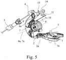
- the lock mechanism 10 is preferably equipped with a central locking lever 11 which is figure 5 is only indicated.
- the central locking lever 11 is in the in figure 5 locking position shown and can be brought into an unlocking position, not shown, wherein the central locking lever 11 disengages the clutch assembly 6 in its locking position.
- the central locking lever 11 In its unlocked position, not shown, which, starting from the figure 5 position shown corresponds to an upwardly pivoted position, the central locking lever 11 preferably releases the engagement of the clutch arrangement 6 .
- the actuating lever 4 for blocking the engagement of the clutch assembly 6 interacts directly with the coupling element 6a.
- the operating lever 4 interacts with the clutch arrangement 6 via a transmission arrangement 12 .
- the transmission arrangement 12 is configured as a transmission arrangement such that a movement initiated on the actuating lever side is converted into a larger movement initiated on the clutch element side.
- a particularly simple way of realizing the transmission arrangement 12 consists in equipping the transmission arrangement 12 with a pivotable transmission lever 13 so that the actuating lever 4 is coupled via the pivotable transmission lever 13 to the clutch arrangement 6, here to the clutch element 6a.
- the transmission lever 13 can be articulated in a stationary pivoting manner.
- the transmission lever 13 is articulated on the actuating lever 4 so as to be pivotable about a transmission lever axis 13a.
- a stop 14 is provided, with which the transmission lever 13 comes into engagement when the actuating lever 4 is moved into its non-actuated state, thereby disengaging the clutch arrangement 6 and blocking engagement of the clutch arrangement 6 .
- a first lever arm 15 comes into engagement with the stop 14 ( 2 ), resulting in a pivoting of the transmission lever 13 about its axis 13a in 2 leads counterclockwise.
- a second lever arm 16 of the transmission lever 13 presses the coupling element 6a in 2 down, i.e. into the disengaged position, so that when the in 1 In the state shown, engagement of the clutch assembly 6 via the transmission lever 13 is blocked.
- the effective lever arm 15 on the stop side is shorter than the effective lever arm 16 on the clutch side.
- the advantageous transmission ratio of the transmission arrangement 12 mentioned above can thus be easily adjusted.
- the two lever arms 15, 16 extend in different directions from the transmission lever axis 13a. 1 shows that the two lever arms 15, 16 even extend substantially in opposite directions from the transmission lever axis 13a.
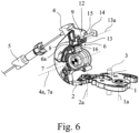
- the transmission lever 13 can be a simple plastic or sheet metal part. A variant that can be produced particularly cost-effectively is shown in FIG 6 , In which the transmission lever 13 is designed from a resiliently bendable wire or strip. In a particularly preferred embodiment, the transmission lever 13 is designed in the manner of a torsion spring, with one spring leg providing the lever arm 15 on the stop side and the other spring leg providing the lever arm 16 on the clutch side. The spring coils of the torsion spring adjust as in 6 shown, the pivot axis 13a of the transmission lever 13 on the operating lever 4 ready.
- the clutch arrangement 6 has an adjustable clutch element 6a, which can be moved into an engaged position corresponding to the engaged state and into a disengaged position corresponding to the disengaged state.
- the coupling element 6a is here and preferably a resiliently flexible wire or strip which can be bent between the engaged position and the disengaged position.
- the fact that the coupling element 6a can be prestressed into the engaged position by its own spring elasticity is particularly advantageous. As a result, the above-mentioned, spring-driven engagement of the clutch arrangement 6 can be achieved in a particularly simple manner.
- the coupling element 6a is preferably part of a torsion spring, the spring coils of which are aligned here and preferably parallel to the actuating lever axis 4a.
- the lock latch axis 1a and the pawl axis 2a are aligned parallel to one another, but perpendicular to the actuating lever axis 4a.
- the pivot axis, not shown, of the central locking lever 11 is here and preferably aligned parallel to the actuating axis 4a. Overall, this results in an arrangement in which, in particular, the actuating lever 4 and the pawl lever 7 can be nested in one another in a space-saving manner.
- the operating lever 4 is an external operating lever of the motor vehicle lock, as discussed above, in the illustrated and therefore preferred exemplary embodiment, which can be operated via an external door handle 17 .
- a door handle 17, in particular an outside door handle 17, is provided and that in any case the actuating lever 4, preferably also the clutch arrangement 6, is or are a component or components of the door handle 17 and/or is or are accommodated in the door handle 17 . are.
- the actuating lever 4 is then preferably part of a handle of the door handle 17 or the handle itself.
- the door handle 17, in particular the actuating lever 4 via the clutch arrangement 6, is then preferably driven by means of a Bowden cable or the like with the motor vehicle lock and there with the pawl 2 coupled or coupled via a possibly existing lock mechanism. All of the above explanations apply accordingly to such an embodiment.
- Such a door handle 17, which has both the operating lever 4 and the clutch arrangement 6, is the subject of a further independent teaching.
- the motor vehicle lock of the proposed motor vehicle lock arrangement is claimed as such. Reference may be made to all statements on the motor vehicle lock arrangement that are suitable for describing the motor vehicle lock as such. In particular, all explained variants of the proposed motor vehicle lock arrangement, insofar as they relate to the motor vehicle lock, can be applied accordingly to the further teaching.
Landscapes
- Engineering & Computer Science (AREA)
- Mechanical Engineering (AREA)
- Lock And Its Accessories (AREA)
Description
- Die Erfindung betrifft eine Kraftfahrzeugschlossanordnung mit den Merkmalen des Oberbegriffs von Anspruch 1, ein Kraftfahrzeugschloss mit den Merkmalen des Oberbegriffs von Anspruch 14 sowie einen Türgriff und Kraftfahrzeugschloss mit den Merkmalen des Oberbegriffs von Anspruch 15.
- Die in Rede stehende Kraftfahrzeugschlossanordnung ist jedenfalls mit einem Kraftfahrzeugschloss ausgestattet. Regelmäßig ist die Kraftfahrzeugschlossanordnung auch mit einem Türgriff, insbesondere mit einem Türinnengriff und/oder Türaußengriff ausgestattet, um das Kraftfahrzeugschloss über eine entsprechende Benutzerbetätigung öffnen zu können. Der Begriff "Kraftfahrzeugschloss" ist vorliegend weit auszulegen. Er umfasst alle Arten von Tür-, Hauben- oder Klappenschlössern. Vorliegend steht das einer Tür eines Kraftfahrzeugs zugeordnete Kraftfahrzeugschloss im Vordergrund. Dies ist nicht beschränkend zu verstehen.
- Der Crashsicherheit der in Rede stehenden Kraftfahrzeugschlossanordnung kommt heute zunehmende Bedeutung zu. Dabei geht es im vorliegenden Sinne darum sicherzustellen, dass die Türen des Kraftfahrzeugs durch die hohen im Crashfall auftretenden Crashbeschleunigungen nicht aufspringen. Ein Seitenaufprall kann beispielsweise dazu führen, dass ein Türaußengriff aufgrund seiner Massenträgheit gewissermaßen "stehenbleibt", was insgesamt zu einer Relativbewegung zwischen Türaußengriff und Fahrzeugtür führt. Das Ergebnis ist ein durch die Crashbeschleunigungen selbsttätig erfolgender und natürlich unerwünschter Betätigungsvorgang.
- In der
DE 20 2010 015 103 U1 ist ein Türgriff zum Vermeiden eines Betätigungsvorgangs in einer Crashsituation beschrieben. - Die bekannte Kraftfahrzeugschlossanordnung (
DE 20 2009 017 667 U1 ), von dem die Erfindung ausgeht, ist mit einem Kraftfahrzeugschloß ausgestattet, das mit die üblichen Schließelementen Schlossfalle und Sperrklinke aufweist, wobei sich die Sperrklinke in ebenfalls üblicher Weise mittels eines Betätigungshebels ausheben lässt. Dabei ist regelmäßig zwischen dem Betätigungshebel und der Sperrklinke eine schaltbare Kupplungsanordnung angeordnet, über die je nach Schlosszustand des Kraftfahrzeugschlosses eine antriebstechnische Verbindung zwischen dem Betätigungshebel und der Sperrklinke herstellbar bzw. trennbar ist. - Zur Gewährleistung einer hohen Crashsicherheit ist bei der bekannten Kraftfahrzeugschlossanordnung ein vom Betätigungshebel separat angeordnetes Crashelement vorgesehen, das den Betätigungshebel im Crashfall blockiert. Damit ist sichergestellt, dass eine selbsttätige, durch die Crashbeschleunigungen verursachte Betätigung des Betätigungshebels und damit ein unerwünschtes Ausheben der Sperrklinke nicht stattfindet. Allerdings muss der Blockierwirkung stets eine Beschleunigung des Crashelements in eine Blockierstellung vorausgehen, was dazu führt, dass das Crashelement bei manchen Crashbeschleunigungen nicht optimal anspricht. Ferner sind bei der crashbedingten Blockierung des Betätigungshebels regelmäßig hohe Blockierkräfte aufzubringen, was mit einer hohen Belastung der beteiligten Bauteile und einem entsprechenden Ausfallrisiko einhergeht. Der Erfindung liegt das Problem zugrunde, die bekannte Kraftfahrzeugschlossanordnung derart auszugestalten und weiterzubilden, dass die Crashsicherheit hinsichtlich eines unerwünschten, crashbedingten Aushebens der Sperrklinke erhöht wird.
- Das obige Problem wird bei einer Kraftfahrzeugschlossanordnung gemäß dem Oberbegriff von Anspruch 1 durch die Merkmale des kennzeichnenden Teils von Anspruch 1 gelöst.
- Wesentlich ist, dass der Betätigungshebel in ganz bestimmter Weise mit der Kupplungsanordnung zwischen dem Betätigungshebel und der Sperrklinke zusammenwirkt, nämlich derart, dass der Betätigungshebel bei Verstellung in seinen unbetätigten Zustand die eingekuppelte Kupplungsanordnung auskuppelt und die ausgekuppelte Kupplungsanordnung im ausgekuppelten Zustand belässt und das Einkuppeln der Kupplungsanordnung während seines unbetätigten Zustands sperrt und erst im Zuge seiner Betätigung freigibt, so dass das Einkuppeln der Kupplungsanordnung im unbetätigten Zustand des Betätigungshebels verhindert wird. Letztlich sorgt dieses
- Zusammenwirken zwischen Betätigungshebel und Kupplungsanordnung dafür, dass die Kupplungsanordnung bei unbetätigtem Betätigungshebel stets ausgekuppelt ist.
- Interessant bei der vorschlagsgemäßen Lösung ist die Tatsache, dass das Einkuppeln der Kupplungsanordnung insbesondere trägheitsbedingt eine gewisse Zeit in Anspruch nimmt, was bei geeigneter Auslegung dazu führen kann, dass eine crashbedingte und entsprechend schnelle Betätigung des Betätigungshebels mangels rechtzeitigen Einkuppelns der Kupplungsanordnung einen Leerhub durchführt. Mit der vorschlagsgemäßen Lösung ist bei geeigneter Auslegung die Crashsicherheit dadurch besonders hoch, dass im Crashfall keine Beschleunigung von Crashelementen o. dgl. notwendig ist, um eine crashbedingte Betätigung des Betätigungshebels in einen Leerhub zu überführen. Vielmehr wird vorgeschlagen, dass die Komponenten, die im Crashfall den ausgekuppelten Zustand der Kupplungsanordnung garantieren, in einem solchen Crashfall trägheitsbedingt möglichst in ihrer jeweiligen Stellung verbleiben. Man könnte auch sagen, dass das vorschlagsgemäße Kraftfahrzeugschloss bei unbetätigtem Betätigungshebel bereits crashsicher ist.
- Die bevorzugten Ausgestaltungen gemäß den Ansprüchen 2 bis 4 betreffen bevorzugte Auslegungsvarianten, die gewährleisten, dass der Betätigungshebel durch crashbedingte Beschleunigungen allenfalls einen Leerhub ausführen kann.
- Bei der besonders bevorzugten Ausgestaltung gemäß Anspruch 5 ist die Kupplungsanordnung Bestandteil einer Schlossmechanik, die in üblicher Weise verriegelbar und entriegelbar ist. Hierbei handelt es sich regelmäßig um stationäre Zustände, die vorzugsweise über einen Zentralverriegelungshebel eingestellt werden.
- Die weiter bevorzugten Ausgestaltungen gemäß den Ansprüchen 6 bis 10 betreffen vorteilhafte Varianten für die Realisierung des Zusammenwirkens zwischen dem Betätigungshebel und der Kupplungsanordnung. Gemäß den Ansprüchen 7 bis 10 findet hierfür ein Übertragungshebel Anwendung, mit dem auf einfache Weise ein vorbestimmtes Übersetzungsverhalten eingestellt werden kann, so dass die Freigabe der Kupplungsanordnung in einem allerersten Betätigungsabschnitt der Betätigungsbewegung stattfinden kann. Eine besonders einfach zu realisierende Ausgestaltung des Übertragungshebels zeigt Anspruch 10, nach dem der Übertragungshebel in einer Variante nach Art einer Schenkelfeder ausgestaltet ist.
- In weiter bevorzugter Ausgestaltung gemäß Anspruch 12 handelt es sich bei dem Kupplungselement der Kupplungsanordnung um einen federelastisch biegbaren Draht oder Streifen, der zwischen der Einkuppelstellung und der Auskuppelstellung biegbar ist. Einfacher lässt sich die Kupplungsanordnung kaum realisieren. Nach einer weiteren Lehre gemäß Anspruch 14, der eigenständige Bedeutung zukommt, wird das Kraftfahrzeugschloss der vorschlagsgemäßen Kraftfahrschlossanordnung als solches beansprucht. Alle hier erläuterten Varianten mit den dazugehörigen Vorteilen zu der Kraftfahrzeugschlossanordnung sind auf das Kraftfahrzeugschloss anwendbar.
- Nach einer weiteren Lehre gemäß Anspruch 15, der ebenfalls eigenständige Bedeutung zukommt, wird ein Türgriff und Kraftfahrzeugschloss zum Ausheben der Sperrklinke eines Kraftfahrzeugschlosses als solcher beansprucht. Ein solcher Türgriff ist im montierten Zustand vorzugsweise über einen Bowdenzug mit dem Kraftfahrzeugschloss gekoppelt.
- Vorschlagsgemäß ist ein Betätigungshebel des Türgriffs zum Ausheben der Sperrklinke vorgesehen, wobei zwischen dem Betätigungshebel und der Sperrklinke, also im Antriebsstrang zwischen dem Betätigungshebel und der Sperrklinke, eine schaltbare Kupplungsanordnung des Türgriffs angeordnet ist, über die im eingekuppelten Zustand eine antriebstechnische Verbindung zwischen dem Betätigungshebel und der Sperrklinke herstellbar ist und im ausgekuppelten Zustand die antriebstechnische Verbindung zwischen dem Betätigungshebel und der Sperrklinke trennbar ist.
- Wesentlich nach dieser weiteren Lehre ist, dass der Betätigungshebel derart mit der Kupplungsanordnung zusammenwirkt, dass der Betätigungshebel bei Verstellung in seinen unbetätigten Zustand die eingekuppelte Kupplungsanordnung auskuppelt und die ausgekuppelte Kupplungsanordnung im ausgekuppelten Zustand belässt und das Einkuppeln der Kupplungsanordnung während seines unbetätigten Zustands sperrt und erst im Zuge seiner Betätigung freigibt, so dass das Einkuppeln der Kupplungsanordnung im unbetätigten Zustand des Betätigungshebels verhindert wird, wobei die Kupplungsanordnung im Zuge der Betätigung des Betätigungshebels federgetrieben einkuppelbar ist derart, dass die Sperrklinke im Normalbetrieb durch eine insbesondere weitergehende Betätigung des Betätigungshebels aushebbar ist.
- Grundsätzlich entspricht die weitere Lehre dem Funktionsprinzip der vorschlagsgemäßen Kraftfahrzeugschlossanordnung, wobei jedenfalls der Betätigungshebel und ggf. auch die Kupplungsanordnung im Türgriff untergebracht sind. Insoweit darf auf alle Ausführungen zu der vorschlagsgemäßen Kraftfahrzeugschlossanordnung verwiesen werden.
- Im Folgenden wird die Erfindung anhand einer lediglich Ausführungsbeispiele darstellenden Zeichnung näher erläutert. In der Zeichnung zeigt
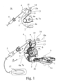
- Fig. 1
- die für die vorschlagsgemäße Lösung wesentlichen Komponenten einer vorschlagsgemäßen Kraftfahrzeugschloßanordnung im Normalbetrieb bei unbetätigtem Betätigungshebel,
- Fig. 2
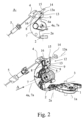
- die Anordnung gemäß
Fig. 1 im Normalbetrieb bei halbbetätigtem Betätigungshebel, - Fig. 3
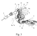
- die Anordnung gemäß
Fig. 1 im Normalbetrieb bei vollbetätigtem Betätigungshebel, - Fig. 4
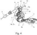
- die Anordnung gemäß
Fig. 1 im Crashfall bei crashbedingt betätigtem Betätigungshebel, - Fig. 5
- die Anordnung gemäß
Fig. 1 im Normalbetrieb mit einem in der Verriegelungsstellung befindlichen Zentralverriegelungshebel und - Fig. 6
- die für die vorschlagsgemäße Lösung wesentlichen Komponenten einer weiteren vorschlagsgemäßen Kraftfahrzeugschloßanordnung im Normalbetrieb bei unbetätigtem Betätigungshebel.
- Die vorschlagsgemäße Kraftfahrzeugschlossanordnung ist mit einem Kraftfahrzeugschloss ausgestattet. Unter dem Begriff "Kraftfahrzeugschloss" sind, wie im einleitenden Teil der Beschreibung schon angesprochen, alle Arten von Tür-, Hauben- oder Klappenschlössern zusammengefasst.
- Das in der Zeichnung dargestellte Kraftfahrzeugschloss ist lediglich mit den Komponenten gezeigt, die für die Erläuterung der vorschlagsgemäßen Lehre wesentlich sind.
- Das Kraftfahrzeugschloss ist mit den üblichen Schließelementen Schlossfalle 1 und Sperrklinke 2 ausgestattet, wobei die Schlossfalle 1 in eine Offenstellung, in eine in der Zeichnung dargestellte Hauptschließstellung und ggf. in eine Vorschließstellung verstellbar ist. Die Schlossfalle 1 wirkt in ebenfalls üblicher Weise mit einem in
Fig. 1 lediglich angedeuteten Schließkeil 3 o. dgl. zusammen, der vorzugsweise karosseriefest angeordnet ist. - Die Sperrklinke 2 ist in die in den
Fig. 1 ,2 und4 bis 6 dargestellte, eingefallene Stellung bringbar, in der sie die Schlossfalle 1 in der jeweiligen Schließstellung hält. Die Sperrklinke 2 ist hier und vorzugsweise in ihre eingefallene Stellung vorgespannt und in eine ausgehobene Stellung bringbar, in der sie außer Eingriff von der Schlossfalle steht (Fig. 3 ), so dass die Schlossfalle 1 inFig. 3 gegen den Uhrzeigersinn in die Offenstellung schwenken kann. - Zum Ausheben der Sperrklinke 2 ist ein Betätigungshebel 4 vorgesehen. Bei dem dargestellten und insoweit bevorzugten Ausführungsbeispiel handelt es sich bei dem Betätigungshebel 4 um einen Außenbetätigungshebel, der über ein Kraftübertragungselement, hier über einen Bowdenzug 5, mit einem in
Fig. 1 nur angedeuteten Türaußengriff 17 gekoppelt ist. So lässt sich die Sperrklinke 2 über eine Betätigung des Türaußengriffs 17 ausheben, sofern der noch zu erläuternde Schlosszustand des Kraftfahrzeugschlosses dies zulässt. - Zwischen dem Betätigungshebel 4 und der Sperrklinke 2 ist eine schaltbare Kupplungsanordnung 6 angeordnet. Damit ist gemeint, dass die Kupplungsanordnung 6 im Antriebsstrang zwischen Betätigungshebel 4 und Sperrklinke 2 gelegen ist. Im eingekuppelten Zustand (
Fig. 2 ,3 ) stellt die Kupplungsanordnung 6 hier eine antriebstechnische Verbindung zwischen dem Betätigungshebel 4 und der Sperrklinke 2 her. Im ausgekuppelten Zustand (Fig. 1 ,4 bis 6 ) trennt die Kupplungsanordnung 6 die antriebstechnische Verbindung zwischen Betätigungshebel 4 und Sperrklinke 2. - Im Einzelnen ist die Kupplungsanordnung 6 antriebstechnisch zwischen dem Betätigungshebel 4 und einem Sperrklinkenhebel 7 gelegen, der wiederum auf die Sperrklinke 2 wirkt. Ein Ausheben der Sperrklinke 2 erfolgt also über den Betätigungshebel 4 und den Sperrklinkenhebel 7.
- Die Kupplungsanordnung 6 ist mit einem verstellbaren Kupplungselement 6a ausgestattet, das in noch zu erläuternder Weise als federelastisch biegbarer Draht ausgestaltet ist. Dem Kupplungselement 6a sind einerseits zwei parallele, sperrklinkenhebelseitige Steuerkanten 8 und andererseits eine betätigungshebelseitige Steuerkante 9 zugeordnet.
- Im Eingriffsbereich sind die Steuerkanten 8, 9 im Wesentlichen senkrecht zu der Erstreckung des drahtförmigen Kupplungselements 6a ausgerichtet. Die jeweils übertragene Kraft ist im Wesentlichen senkrecht zu der Erstreckung des drahtförmigen Kupplungselements 6a ausgerichtet.
- Das Kupplungselement 6a ist nun in eine Auskuppelstellung (
Fig. 1 ) bringbar, in der es jedenfalls außer Eingriff von der betätigungshebelseitigen Steuerkante 9 steht, so dass der Betätigungshebel 4 bei seiner Betätigung, in der Zeichnung gegen den Uhrzeigersinn, grundsätzlich einen Leerhub durchführen würde, sofern das Kupplungselement 6a in seiner Auskuppelstellung verbleiben würde. - Das Kupplungselement 6a lässt sich ferner in eine Einkuppelstellung verstellen (
Fig. 2 ), in der es in Eingriff sowohl mit den sperrklinkenhebelseitigen Steuerkanten 8 als auch mit der betätigungshebelseitigen Steuerkante 9 steht bzw. bringbar ist. Das Kupplungselement 6a stellt hier eine antriebstechnische Verbindung zwischen dem Betätigungshebel 4 und dem Sperrklinkenhebel 7 und damit zu der Sperrklinke 2 her. Eine Betätigung des Betätigungshebels 4 führt zum Ausheben der Sperrklinke 2, wie inFig. 3 gezeigt. - Eine Verstellung des Kupplungselements 6a zwischen der Auskuppelstellung (
Fig. 1 ) und der Einkuppelstellung (Fig. 2 ) entspricht in der Zeichnung einer Verstellung zwischen der unteren Stellung und der oberen Stellung des Kupplungselements 6a. - Vorschlagsgemäß wirkt der Betätigungshebel 4 derart mit der Kupplungsanordnung 6 zusammen, dass der Betätigungshebel 4 bei Verstellung in seinen unbetätigten Zustand (
Fig. 1 ) die eventuell eingekuppelte Kupplungsanordnung 6 auskuppelt und die eventuell ausgekuppelte Kupplungsanordnung 6 im ausgekuppelten Zustand belässt und das Einkuppeln der Kupplungsanordnung 6 während seines unbetätigten Zustands sperrt und erst im Zuge seiner Betätigung freigibt (Fig. 2 ,3 ). Wie dies im Einzelnen von Statten geht, wird weiter unten erläutert. Wesentlich ist zunächst, dass eine Verstellung des Betätigungshebels 4 in seinen unbetätigten Zustand (Fig. 1 ) stets mit der ausgekuppelten Kupplungsanordnung 6 endet. Bei einer solchen Verstellung des Betätigungshebels 4 in seinen unbetätigten Zustand handelt es sich hier und vorzugsweise um die Rückstellung des Betätigungshebels 4 im Uhrzeigersinn nach einer oben angesprochenen Betätigung des Betätigungshebels 4 gegen den Uhrzeigersinn. Dabei kann die Kupplungsanordnung 6 je nach zu erläuterndem Schlosszustand schon vorher ausgekuppelt sein, oder erst durch die Verstellung des Betätigungshebels 4 in seinen unbetätigten Zustand ausgekuppelt werden. - Wesentlich ist weiter, dass der Betätigungshebel 4 in seinem unbetätigten, in
Fig. 1 gezeigten Zustand das Einkuppeln der Kupplungsanordnung 6 sperrt, also insoweit die Verstellung des Kupplungselements 6a in die in der Zeichnung obere Stellung, nicht erlaubt. Erst im Zuge der Betätigung des Betätigungshebels 4 ist es der Kupplungsanordnung 6 möglich, das Kupplungselement 6a in die obere Stellung, also in die Einkuppelstellung, zu verstellen. - Der Begriff "Sperren des Einkuppelns der Kupplungsanordnung" ist vorliegend weit zu verstehen. Er bedeutet ganz allgemein, dass das Einkuppeln der Kupplungsanordnung 6 verhindert wird, wobei ein Kraftfluss zwischen dem Betätigungshebel 4 und dem Kupplungselement 6a nicht ständig vorgesehen sein muss. Beispielsweise kann es auch sein, dass das Kupplungselement 6a zeitweise im Rahmen einer noch zu erläuternden Zentralverriegelungsfunktion in der Auskuppelstellung gehalten wird, so dass das Einkuppeln durch den Betätigungshebel 4 zwar immer noch gesperrt ist, ein Kraftschluss zwischen Betätigungshebel 4 und Kupplungselement 6a aber nicht vorliegt. Insoweit kann im gesperrten Zustand sogar ein gewisses Spiel zwischen dem Betätigungshebel 4 und dem Kupplungselement 6a vorliegen.
- Bei geeigneter Auslegung ist es so, dass die Kupplungsanordnung 6 im Zuge der Betätigung des Betätigungshebels 4 federgetrieben einkuppelbar ist derart, dass die Sperrklinke 2 im Normalbetrieb durch eine weitergehende Betätigung des Betätigungshebels 4 aushebbar ist. Ein kompletter Betätigungshub umfasst also zunächst das Einkuppeln der Kupplungsanordnung 6 und anschließend das Ausheben der Sperrklinke 2, sofern die Betätigung des Betätigungshebels 4 im Normalbetrieb, also mit einer normalen Betätigungsgeschwindigkeit erfolgt. Der Begriff "Normalbetrieb" grenzt sich vorliegend gegenüber dem Betrieb im Crashfall ab. Der Normalbetrieb zeichnet sich insbesondere dadurch aus, dass die Betätigung des Betätigungshebels mit normaler Betätigungsgeschwindigkeit, die üblicherweise auf eine manuelle Benutzerbetätigung zurückgeht, erfolgt.
- Das Einkuppeln der Kupplungsanordnung 6 erfolgt trägheitsbedingt stets mit einer gewissen Verzögerung nach der Freigabe durch den Betätigungshebel 4. Hier spielt das Trägheitsverhalten des Kupplungselements 6a und der an der Verstellung des Kupplungselements 6a beteiligten Komponenten die wesentliche Rolle.
- Die trägheitsbedingte Verzögerung beim Einkuppeln der Kupplungsanordnung 6 wird vorschlagsgemäß genutzt, um eine crashbedingte, unerwünschte Betätigung des Betätigungshebels 4 in einen Leerhub zu überführen. Im Einzelnen wird vorgeschlagen, dass bei einer Betätigung des Betätigungshebels 4 mit einer Betätigungsgeschwindigkeit, die oberhalb einer vorbestimmten Grenzgeschwindigkeit liegt, hier und vorzugsweise durch im Crashfall auftretende Crashbeschleunigungen, der Betätigungshebel 4 wegen des hier und vorzugsweise trägheitsbedingt verzögerten Einkuppelns der Kupplungsanordnung 6 einen Leerhub ausführt. Dies ist in
Fig. 4 dargestellt. - Mit der vorschlagsgemäßen Lösung werden besonders schnelle Betätigungsbewegungen also stets in einen Leerhub überführt. Die Auslegung ist so zu treffen, dass hiervon die statistisch zu erwartenden, crashbedingten Betätigungsbewegungen betroffen sind.
- Bei dem dargestellten und insoweit bevorzugten Ausführungsbeispiel umfasst die Betätigung des Betätigungshebels 4 einen Freigabehub, der mit der Freigabe der Kupplungsanordnung 6 zum Einkuppeln einhergeht. Der Freigabehub ergibt sich vom Übergang von
Fig. 1 aufFig. 2 . Ferner umfasst die Betätigung des Betätigungshebels 4 einen Auslösehub, der bei - zwischenzeitlich - eingekuppelter Kupplungsanordnung 6 mit dem Ausheben der Sperrklinke 2 einhergeht. Der Auslösehub ergibt sich aus dem Übergang vonFig. 2 aufFig. 3 . Hier und vorzugsweise schließt sich der Auslösehub unmittelbar an den Freigabehub an. - Der Auslegung des Freigabehubs, insbesondere der Ausdehnung des Freigabehubs, kommt für die vorschlagsgemäße Lösung ganz besondere Bedeutung zu, sofern eine crashbedingte Betätigung des Betätigungshebels 4 in einen Leerhub überführt werden soll. Vorzugsweise ist es nämlich so, dass bei einer Betätigung des Betätigungshebels 4 mit einer Betätigungsgeschwindigkeit, die oberhalb der vorbestimmten Grenzgeschwindigkeit liegt, hier und vorzugsweise durch im Crashfall auftretende Crashbeschleunigungen, die zum Durchlaufen des Freigabehubs benötigte Zeit geringer ist als die zum Einkuppeln insbesondere trägheitsbedingt benötigte Zeit. Nach Abschluss des Freigabehubs ist das Einkuppeln der Kupplungsanordnung 6 also nicht abgeschlossen, so dass im Auslösehub kein Ausheben der Sperrklinke 2 erfolgt. Der Betätigungshebel 4 führt einen Leerhub aus (
Fig. 4 ). - Grundsätzlich kann die Kupplungsanordnung 6 ausschließlich zur Erhöhung der Crashsicherheit im obigen Sinne vorgesehen sein. In besonders bevorzugter Ausgestaltung wird die Kupplungsanordnung 6 aber auch zur Einstellung von Schlosszuständen des Kraftfahrzeugschlosses genutzt. Hierfür ist die Kupplungsanordnung 6 Bestandteil einer Schlossmechanik 10, die der Einstellung verschiedener Schlosszustände dient. Die Schlossmechanik 10 ist in mindestens einen Verriegelungszustand, in dem die Kupplungsanordnung 6 ausgekuppelt ist, und in mindestens einen Entriegelungszustand, in dem die Kupplungsanordnung 6 eingekuppelt ist, bringbar. Die Schlossmechanik 10 lässt sich vorzugsweise motorisch in die jeweiligen Zustände bringen, was grundsätzlich einer Zentralverriegelungsfunktion entspricht.
- Die Schlossmechanik 10 ist vorzugsweise mit einem Zentralverriegelungshebel 11 ausgestattet, der in
Fig. 5 lediglich angedeutet ist. Der Zentralverriegelungshebel 11 ist in die inFig. 5 dargestellte Verriegelungsstellung und in eine nicht dargestellte Entriegelungsstellung bringbar, wobei der Zentralverriegelungshebel 11 in seiner Verriegelungsstellung die Kupplungsanordnung 6 auskuppelt. In seiner nicht dargestellten Entriegelungsstellung, die ausgehend von der inFig. 5 gezeigten Stellung einer nach oben verschwenkten Stellung entspricht, gibt der Zentralverriegelungshebel 11 das Einkuppeln der Kupplungsanordnung 6 vorzugsweise frei. - Interessant bei dem dargestellten und insoweit bevorzugten Ausführungsbeispiel ist die Tatsache, dass der Betätigungshebel 4 und der Zentralverriegelungshebel 11 nach Art einer Oder-Verknüpfung auf die Kupplungsanordnung 6 wirken. Solange der Betätigungshebel 4 in seinem unbetätigten Zustand oder der Zentralverriegelungshebel 11 in seiner Verriegelungsstellung steht, befindet sich die Kupplungsanordnung 6 zwangsläufig in ihrem ausgekuppelten Zustand.
- Grundsätzlich ist es denkbar, dass der Betätigungshebel 4 zum Sperren des Einkuppelns der Kupplungsanordnung 6 unmittelbar mit dem Kupplungselement 6a zusammenwirkt. Hier und vorzugsweise ist es allerdings so, dass der Betätigungshebel 4 über eine Übertragungsanordnung 12 mit der Kupplungsanordnung 6 zusammenwirkt. Dabei ist es in besonders bevorzugter Ausgestaltung vorgesehen, dass die Übertragungsanordnung 12 als Übersetzungsanordnung ausgestaltet ist derart, dass eine betätigungshebelseitig eingeleitete Bewegung in eine größere kupplungselementseitig ausgeleitete Bewegung überführt wird. Durch eine geeignete Auslegung der Übertragungsanordnung 12, insbesondere der Übersetzung der Übertragungsanordnung 12, lässt sich die oben angesprochene Auslegung der Ausdehnung des Freigabehubs punktgenau vornehmen.
- Eine besonders einfache Möglichkeit der Realisierung der Übertragungsanordnung 12 besteht in der Ausstattung der Übertragungsanordnung 12 mit einem schwenkbaren Übertragungshebel 13, so dass der Betätigungshebel 4 über den schwenkbaren Übertragungshebel 13 mit der Kupplungsanordnung 6, hier mit dem Kupplungselement 6a, gekoppelt ist. Der Übertragungshebel 13 kann grundsätzlich ortsfest schwenkbar angelenkt sein. Hier und vorzugsweise ist der Übertragungshebel 13 allerdings auf dem Betätigungshebel 4 um eine Übertragungshebelachse 13a schwenkbar angelenkt.
- Weiter vorzugsweise ist ein Anschlag 14 vorgesehen, mit dem der Übertragungshebel 13 bei einer Verstellung des Betätigungshebels 4 in seinen unbetätigten Zustand in Eingriff kommt und dabei die Kupplungsanordnung 6 auskuppelt sowie ein Einkuppeln der Kupplungsanordnung 6 sperrt. Dies ergibt sich durch den Übergang von
Fig. 2 aufFig. 1 . Dabei kommt ein erster Hebelarm 15 in Eingriff mit dem Anschlag 14 (Fig. 2 ), was zu einem Schwenken des Übertragungshebels 13 um seine Achse 13a inFig. 2 gegen den Uhrzeigersinn führt. Gleichzeitig drückt ein zweiter Hebelarm 16 des Übertragungshebels 13 das Kupplungselement 6a inFig. 2 nach unten, also in die Auskuppelstellung, so dass beim Erreichen des inFig. 1 dargestellten Zustands ein Einkuppeln der Kupplungsanordnung 6 über den Übertragungshebel 13 gesperrt ist. - Hier und vorzugsweise ist bei unbetätigtem Betätigungshebel 4 der wirksame anschlagsseitige Hebelarm 15 kürzer als der wirksame kupplungsseitige Hebelarm 16. Damit lässt sich die oben angesprochene, vorteilhafte Übersetzung der Übertragungsanordnung 12 leicht einstellen.
- Bei dem dargestellten und insoweit bevorzugten Ausführungsbeispiel erstrecken sich die beiden Hebelarme 15, 16 in unterschiedlichen Richtungen von der Übertragungshebelachse 13a.
Fig. 1 zeigt, dass sich die beiden Hebelarme 15, 16 sogar im Wesentlichen in entgegengesetzten Richtungen von der Übertragungshebelachse 13a erstrecken. - Bei dem Übertragungshebel 13 kann es sich um ein einfaches Kunststoff- oder Blechteil handeln. Eine besonders kostengünstig herstellbare Variante zeigt die Darstellung gemäß
Fig. 6 , bei der der Übertragungshebel 13 aus einem federelastisch biegbaren Draht oder Streifen ausgestaltet ist. In besonders bevorzugter Ausgestaltung ist der Übertragungshebel 13 nach Art einer Schenkelfeder ausgestaltet, wobei der eine Federschenkel den anschlagsseitigen Hebelarm 15 und der andere Federschenkel den kupplungsseitigen Hebelarm 16 bereitstellt. Die Federwindungen der Schenkelfeder stellen, wie inFig. 6 gezeigt, die Schwenkachse 13a des Übertragungshebels 13 auf dem Betätigungshebel 4 bereit. - Es wurde schon erläutert, dass die Kupplungsanordnung 6 ein verstellbares Kupplungselement 6a aufweist, das in eine dem eingekuppelten Zustand entsprechende Einkuppelstellung und in eine dem ausgekuppelten Zustand entsprechende Auskuppelstellung verstellbar ist. Bei dem Kupplungselement 6a handelt es sich hier und vorzugsweise um einen federelastisch biegbaren Draht oder Streifen, der zwischen der Einkuppelstellung und der Auskuppelstellung biegbar ist. Besonders vorteilhaft ist dabei die Tatsache, dass das Kupplungselement 6a durch seine eigene Federelastizität in die Einkuppelstellung vorgespannt sein kann. Dadurch lässt sich das oben angesprochene, federgetriebene Einkuppeln der Kupplungsanordnung 6 auf ganz besonders einfache Weise erreichen.
- Im Folgenden wird die Funktionsweise des vorschlagsgemäßen Kraftfahrzeugschlosses zusammengefasst: Bei in der Entriegelungsstellung stehendem Zentralverriegelungshebel 11 bewirkt eine Betätigung des Betätigungshebels 4 aus der in
Fig. 1 gezeigten Stellung heraus, dass das Kupplungselement 6a durch seine Federelastizität in der Zeichnung nach oben drängt und den Übertragungshebel 13 um seine Übertragungshebelachse 13a im Uhrzeigersinn schwenkt. Dadurch, dass die Betätigung hier mit normaler Betätigungsgeschwindigkeit erfolgt, kommt das Kupplungselement 6a in den Bewegungsbereich der betätigungshebelseitigen Steuerkante 9, bevor die betätigungshebelseitige Steuerkante 9 das Kupplungselement 6a passiert. Dadurch wird, wie inFig. 3 gezeigt, das Kupplungselement 6a von der betätigungshebelseitigen Steuerkante 9 mitgenommen, wirkt auf die sperrklinkenhebelseitige Steuerkant 8 und führt zu einem Verschwenken des Sperrklinkenhebels 7 inFig. 3 gegen den Uhrzeigersinn und damit zu einem Ausheben der Sperrklinke 2. - Geht die Betätigung des Betätigungshebels 4 allerdings auf einen Crashfall zurück, so handelt es sich hierbei regelmäßig um eine Betätigung mit besonders hoher Betätigungsgeschwindigkeit. Bei geeigneter Auslegung passiert die Betätigungshebelseitige Steuerkante 9 das Kupplungselement 6a, bevor das Kupplungselement 6a die Einkuppelstellung erreicht hat. Entsprechend kommt es zu keiner antriebstechnischen Verbindung zwischen dem Betätigungshebel 4 und dem Sperrklinkenhebel 7, so dass der Betätigungshebel 4, wie in
Fig. 4 dargestellt, einen Leerhub ausführt. - Erwähnenswert ist noch die Tatsache, dass für den Fall, dass der Zentralverriegelungshebel 11 in der in
Fig. 5 dargestellten Verriegelungsstellung steht, der oben beschriebene, vorschlagsgemäße Mechanismus nicht einsetzt. Der Grund hierfür besteht darin, dass der Zentralverriegelungshebel 11 das Kupplungselement 6a bereits in der Auskuppelstellung hält, so dass der Betätigungshebel 4 ohnehin einen Leerhub durchführt. - Es darf darauf hingewiesen werden, dass die vorschlagsgemäße Anordnung eine besonders hohe Kompaktheit aufweist. Hervorzuheben ist dabei die Tatsache, dass der Sperrklinkenhebel 7 um eine Sperrklinkenachse 7a schwenkbar ist, die konzentrisch zu der Betätigungshebelachse 4a des Betätigungshebels 4 ausgerichtet ist. Das Kupplungselement 6a ist vorzugsweise Bestandteil einer Schenkelfeder, deren Federwindungen hier und vorzugsweise parallel zu der Betätigungshebelachse 4a ausgerichtet sind. Die Schlossfallenachse 1a und die Sperrklinkenachse 2a sind parallel zueinander, jedoch senkrecht zu der Betätigungshebelachse 4a ausgerichtet. Die nicht dargestellte Schwenkachse des Zentralverriegelungshebels 11 ist hier und vorzugsweise parallel zu der Betätigungsachse 4a ausgerichtet. Damit ergibt sich insgesamt eine Anordnung, bei der sich insbesondere der Betätigungshebel 4 und der Sperrklinkenhebel 7 auf bauraumsparende Weise ineinander verschachteln lassen.
- Es darf schließlich darauf hingewiesen werden, dass der Betätigungshebel 4 wie oben angesprochen bei dem dargestellten und insoweit bevorzugten Ausführungsbeispiel ein Außenbetätigungshebel des Kraftfahrzeugschlosses ist, der über einen Türaußengriff 17 betätigbar ist.
- Denkbar ist aber auch, dass ein Türgriff 17, insbesondere ein Türaußengriff 17, vorgesehen ist und dass jedenfalls der Betätigungshebel 4, vorzugsweise auch die Kupplungsanordnung 6, Bestandteil bzw. Bestandteile des Türgriffs 17 ist bzw. sind und/oder im Türgriff 17 untergebracht ist bzw. sind. Vorzugsweise ist der Betätigungshebel 4 dann Bestandteil einer Handhabe des Türgriffs 17 oder die Handhabe selbst. Der Türgriff 17, insbesondere der Betätigungshebel 4 über die Kupplungsanordnung 6, ist dann vorzugsweise mittels eines Bowdenzugs o. dgl. mit dem Kraftfahrzeugschloss und dort mit der Sperrklinke 2 antriebstechnisch gekoppelt oder über eine ggf. vorhandene Schlossmechanik koppelbar. Alle obigen Erläuterungen gelten für eine derartige Ausgestaltung entsprechend. Ein solcher Türgriff 17, der sowohl den Betätigungshebel 4 als auch die Kupplungsanordnung 6 aufweist, ist Gegenstand einer weiteren, eigenständigen Lehre.
- Nach einer weiteren Lehre, der ebenfalls eigenständige Bedeutung zukommt, wird das Kraftfahrzeugschloss der vorschlagsgemäßen Kraftfahrzeugschlossanordnung als solches beansprucht. Auf alle Ausführungen zu der Kraftfahrzeugschlossanordnung, die geeignet sind, das Kraftfahrzeugschloss als solches zu beschreiben, darf verwiesen werden. Insbesondere sind alle erläuterten Varianten zu der vorschlagsgemäßen Kraftfahrzeugschlossanordnung, soweit sie das Kraftfahrzeugschloss betreffen, auf die weitere Lehre entsprechend anwendbar.
Claims (15)
- Kraftfahrzeugschlossanordnung mit einem Kraftfahrzeugschloss, wobei das Kraftfahrzeugschloss die Schließelemente Schlossfalle (1) und Sperrklinke (2) aufweist, wobei die Schlossfalle (1) in eine Offenstellung, in eine Hauptschließstellung und ggf. in eine Vorschließstellung verstellbar ist, wobei die Sperrklinke (2) in eine eingefallene Stellung, in der sie die Schlossfalle (1) in einer Schließstellung hält, und in eine ausgehobene Stellung, in der sie außer Eingriff von der Schlossfalle (1) steht, verstellbar ist, wobei ein Betätigungshebel (4) zum Ausheben der Sperrklinke (2) vorgesehen ist, wobei zwischen dem Betätigungshebel (4) und der Sperrklinke (2) eine schaltbare Kupplungsanordnung (6) angeordnet ist, über die im eingekuppelten Zustand eine antriebstechnische Verbindung zwischen dem Betätigungshebel (4) und der Sperrklinke (2) herstellbar ist und im ausgekuppelten Zustand die antriebstechnische Verbindung zwischen dem Betätigungshebel (4) und der Sperrklinke (2) trennbar ist,
dadurch gekennzeichnet,dass der Betätigungshebel (4) derart mit der Kupplungsanordnung (6) zusammenwirkt, dass der Betätigungshebel (4) bei Verstellung in seinen unbetätigten Zustand die eingekuppelte Kupplungsanordnung (6) auskuppelt und die ausgekuppelte Kupplungsanordnung (6) im ausgekuppelten Zustand belässt und das Einkuppeln der Kupplungsanordnung (6) während seines unbetätigten Zustands sperrt und erst im Zuge seiner Betätigung freigibt, so dass das Einkuppeln der Kupplungsanordnung im unbetätigten Zustand des Betätigungshebels verhindert wird, unddass die Kupplungsanordnung (6) im Zuge der Betätigung des Betätigungshebels (4) federgetrieben einkuppelbar ist derart, dass die Sperrklinke (2) im Normalbetrieb durch eine insbesondere weitergehende Betätigung des Betätigungshebels (4) aushebbar ist. - Kraftfahrzeugschlossanordnung nach Anspruch 1, dadurch gekennzeichnet, dass die Anordnung so getroffen ist, dass bei einer Betätigung des Betätigungshebels (4) mit einer Betätigungsgeschwindigkeit, die oberhalb einer vorbestimmten Grenzgeschwindigkeit liegt, insbesondere durch im Crashfall auftretende Crashbeschleunigungen, der Betätigungshebel (4) wegen des insbesondere trägheitsbedingt verzögerten Einkuppelns der Kupplungsanordnung (6) einen Leerhub ausführt.
- Kraftfahrzeugschlossanordnung nach Anspruch 1 oder 2, dadurch gekennzeichnet, dass die Betätigung des Betätigungshebels (4) einen Freigabehub, der mit der Freigabe der Kupplungsanordnung (6) zum Einkuppeln einhergeht und einen Auslösehub, der bei eingekuppelter Kupplungsanordnung (6) mit dem Ausheben der Sperrklinke (2) einhergeht, umfasst, vorzugsweise, dass sich der Auslösehub insbesondere unmittelbar an den Freigabehub anschließt.
- Kraftfahrzeugschlossanordnung nach Anspruch 3, dadurch gekennzeichnet, dass bei einer Betätigung des Betätigungshebels (4) mit einer Betätigungsgeschwindigkeit, die oberhalb einer vorbestimmten Grenzgeschwindigkeit liegt, insbesondere durch im Crashfall auftretende Crashbeschleunigungen, die zum Durchlaufen des Freigabehubs benötigte Zeit geringer ist als die zum Einkuppeln insbesondere trägheitsbedingt benötigte Zeit, so dass der Betätigungshebei (4) einen Leerhub ausführt.
- Kraftfahrzeugschlossanordnung nach einem der vorhergehenden Ansprüche, dadurch gekennzeichnet, dass die Kupplungsanordnung (6) Bestandteil einer Schlossmechanik (10) ist, die in mindestens einen Verriegelungszustand, in dem die Kupplungsanordnung (6) ausgekuppelt ist, und mindestens einen Entriegelungszustand, in dem die Kupplungsanordnung (6) eingekuppelt ist, bringbar ist, vorzugsweise, dass die Schlossmechanik (10) einen Zentralverriegelungshebel (11) aufweist, der in eine Verriegelungsstellung und in eine Entriegelungsstellung bringbar ist und der in seiner Verriegelungsstellung die Kupplungsanordnung (6) auskuppelt, vorzugsweise, dass der Zentralverriegelungshebel (11) in seiner Entriegelungsstellung das insbesondere federgetriebene Einkuppeln der Kupplungsanordnung (6) freigibt.
- Kraftfahrzeugschlossanordnung nach einem der vorhergehenden Ansprüche, dadurch gekennzeichnet, dass der Betätigungshebel (4) über eine Übertragungsanordnung (12) mit der Kupplungsanordnung (6) zusammenwirkt, vorzugsweise, dass die Übertragungsanordnung (12) als Übersetzungsanordnung ausgestaltet ist derart, dass eine betätigungshebelseitig eingeleitete Bewegung in eine größere ausgeleitete Bewegung überführt wird.
- Kraftfahrzeugschlossanordnung nach einem der vorhergehenden Ansprüche, dadurch gekennzeichnet, dass der Betätigungshebel (4) über einen schwenkbaren Übertragungshebel (13) mit der Kupplungsanordnung (6) gekoppelt ist, vorzugsweise, dass der Übertragungshebel (13) auf dem Betätigungshebel (4) schwenkbar angelenkt ist.
- Kraftfahrzeugschlossanordnung nach Anspruch 7, dadurch gekennzeichnet, dass ein Anschlag (14) vorgesehen ist, mit dem der Übertragungshebel (13) bei einer Verstellung des Betätigungshebels (4) in seinen unbetätigten Zustand in Eingriff kommt und dabei die Kupplungsanordnung (6) auskuppelt und ein Einkuppeln der Kupplungsanordnung (6) sperrt.
- Kraftfahrzeugschlossanordnung nach Anspruch 7 oder 8, dadurch gekennzeichnet, dass der Übertragungshebel (13) einen ersten, anschlagseitigen Hebelarm (15) und einen zweiten, kupplungsseitigen Hebelarm (16) aufweist, vorzugsweise, dass bei unbetätigtem Betätigungshebel (4) der wirksame anschlagseitige Hebelarm (15) kürzer als der wirksame kupplungsseitige Hebelarm (16) ist, weiter vorzugsweise, dass sich die beiden Hebelarme (15, 16) in unterschiedlichen Richtungen von der Übertragungshebelachse (13a) erstrecken.
- Kraftfahrzeugschlossanordnung nach einem der Ansprüche 7 bis 9, dadurch gekennzeichnet, dass der Übertragungshebel (13) aus einem federelastisch biegbaren Draht oder Streifen ausgestaltet ist, vorzugsweise, dass der Übertragungshebel (13) nach Art einer Schenkelfeder ausgestaltet ist, wobei der eine Federschenkel einen anschlagseitigen Hebelarm (15) und der andere Federschenkel einen kupplungsseitigen Hebelarm (16) bereitstellt.
- Kraftfahrzeugschlossanordnung nach einem der vorhergehenden Ansprüche, dadurch gekennzeichnet, dass die Kupplungsanordnung (6) ein verstellbares Kupplungselement (6a) aufweist, das in eine dem eingekuppelten Zustand entsprechende Einkuppelstellung und in eine dem ausgekuppelten Zustand entsprechende Auskuppelstellung verstellbar ist.
- Kraftfahrzeugschlossanordnung nach einem der vorhergehenden Ansprüche, dadurch gekennzeichnet, dass das Kupplungselement (6a) als federelastisch biegbarer Draht oder Streifen ausgestaltet ist, der zwischen der Einkuppelstellung und der Auskuppelstellung biegbar ist, vorzugsweise, dass das Kupplungselement (6a) insbesondere durch seine eigene Federelastizität in die Einkuppelstellung vorgespannt ist.
- Kraftfahrzeugschlossanordnung nach einem der vorhergehenden Ansprüche, dadurch gekennzeichnet, dass ein Türgriff (17), insbesondere ein Türau-ßengriff, vorgesehen ist und dass der Betätigungshebel (4), vorzugsweise auch die Kupplungsanordnung (6), Bestandteil bzw. Bestandteile des Türgriffs (17) ist bzw. sind und/oder im Türgriff (17) untergebracht ist bzw. sind, vorzugsweise, dass der Türgriff (17) mit dem Kraftfahrzeugschloss über ein Kraftübertragungselement, insbesondere über einen Bowdenzug (5), gekoppelt ist.
- Kraftfahrzeugschloss mit den Schließelementen Schlossfalle (1) und Sperrklinke (2), wobei die Schlossfalle (1) in eine Offenstellung, in eine Hauptschließstellung und ggf. in eine Vorschließstellung verstellbar ist, wobei die Sperrklinke (2) in eine eingefallene Stellung, in der sie die Schlossfalle (1) in einer Schließstellung hält, und in eine ausgehobene Stellung, in der sie außer Eingriff von der Schlossfalle (1) steht, verstellbar ist, wobei ein Betätigungshebei (4) zum Ausheben der Sperrklinke (2) vorgesehen ist, wobei zwischen dem Betätigungshebel (4) und der Sperrklinke (2) eine schaltbare Kupplungsanordnung (6) angeordnet ist, über die im eingekuppelten Zustand eine antriebstechnische Verbindung zwischen dem Betätigungshebel (4) und der Sperrklinke (2) herstellbar ist und im ausgekuppelten Zustand die antriebstechnische Verbindung zwischen dem Betätigungshebel (4) und der Sperrklinke (2) trennbar ist,
dadurch gekennzeichnet,dass der Betätigungshebel (4) derart mit der Kupplungsanordnung (6) zusammenwirkt, dass der Betätigungshebel (4) bei Verstellung in seinen unbetätigten Zustand die eingekuppelte Kupplungsanordnung (6) auskuppelt und die ausgekuppelte Kupplungsanordnung (6) im ausgekuppelten Zustand belässt und das Einkuppeln der Kupplungsanordnung (6) während seines unbetätigten Zustands sperrt und erst im Zuge seiner Betätigung freigibt, so dass das Einkuppeln der Kupplungsanordnung im unbetätigten Zustand des Betätigungshebels verhindert wird, unddass die Kupplungsanordnung (6) im Zuge der Betätigung des Betätigungshebels (4) federgetrieben einkuppelbar ist derart, dass die Sperrklinke (2) im Normalbetrieb durch eine insbesondere weitergehende Betätigung des Betätigungshebels (4) aushebbar ist. - Türgriff und Kraftfahrzeugschloss, zum Ausheben der Sperrklinke (2) des Kraftfahrzeugschlosses, wobei das Kraftfahrzeugschloss neben der Sperrklinke (2) eine Schlossfalle (1) aufweist, wobei die Schlossfalle (1) in eine Offenstellung, in eine Hauptschließstellung und ggf. in eine Vorschließstellung verstellbar ist, wobei die Sperrklinke (2) in eine eingefallene Stellung, in der sie die Schlossfalle (1) in einer Schließstellung hält, und in eine ausgehobene Stellung, in der sie außer Eingriff von der Schlossfalle (1) steht, verstellbar ist, wobei ein Betätigungshebel (4) des Türgriffs (17) zum Ausheben der Sperrklinke (2) vorgesehen ist, wobei zwischen dem Betätigungshebel (4) und der Sperrklinke (2) eine schaltbare Kupplungsanordnung (6) des Türgriffs (17) angeordnet ist, über die im eingekuppelten Zustand eine antriebstechnische Verbindung zwischen dem Betätigungshebel (4) und der Sperrklinke (2) herstellbar ist und im ausgekuppelten Zustand die antriebstechnische Verbindung zwischen dem Betätigungshebel (4) und der Sperrklinke (2) trennbar ist,
dadurch gekennzeichnet,dass der Betätigungshebel (4) derart mit der Kupplungsanordnung (6) zusammenwirkt, dass der Betätigungshebel (4) bei Verstellung in seinen unbetätigten Zustand die eingekuppelte Kupplungsanordnung (6) auskuppelt und die ausgekuppelte Kupplungsanordnung (6) im ausgekuppelten Zustand belässt und das Einkuppeln der Kupplungsanordnung (6) während seines unbetätigten Zustands sperrt und erst im Zuge seiner Betätigung freigibt, so dass das Einkuppeln der Kupplungsanordnung im unbetätigten Zustand des Betätigungshebels verhindert wird, unddass die Kupplungsanordnung (6) im Zuge der Betätigung des Betätigungshebels (4) federgetrieben einkuppelbar ist derart, dass die Sperrklinke (2) im Normalbetrieb durch eine insbesondere weitergehende Betätigung des Betätigungshebels (4) aushebbar ist.
Applications Claiming Priority (2)
| Application Number | Priority Date | Filing Date | Title |
|---|---|---|---|
| DE202012007312U DE202012007312U1 (de) | 2012-07-31 | 2012-07-31 | Kraftfahrzeugschlossanordnung |
| PCT/EP2013/065828 WO2014019960A2 (de) | 2012-07-31 | 2013-07-26 | Kraftfahrzeugschlossanordnung |
Publications (3)
| Publication Number | Publication Date |
|---|---|
| EP2880232A2 EP2880232A2 (de) | 2015-06-10 |
| EP2880232B1 EP2880232B1 (de) | 2017-03-08 |
| EP2880232B2 true EP2880232B2 (de) | 2023-08-30 |
Family
ID=48877246
Family Applications (1)
| Application Number | Title | Priority Date | Filing Date |
|---|---|---|---|
| EP13742222.6A Active EP2880232B2 (de) | 2012-07-31 | 2013-07-26 | Kraftfahrzeugschlossanordnung |
Country Status (11)
| Country | Link |
|---|---|
| US (1) | US10132106B2 (de) |
| EP (1) | EP2880232B2 (de) |
| JP (1) | JP6316290B2 (de) |
| KR (1) | KR101810303B1 (de) |
| CN (1) | CN104797768B (de) |
| BR (1) | BR112015002246B1 (de) |
| DE (1) | DE202012007312U1 (de) |
| ES (1) | ES2659576T5 (de) |
| IN (1) | IN2015DN00766A (de) |
| MX (1) | MX361170B (de) |
| WO (1) | WO2014019960A2 (de) |
Families Citing this family (47)
| Publication number | Priority date | Publication date | Assignee | Title |
|---|---|---|---|---|
| DE202009017667U1 (de) | 2009-12-26 | 2011-05-05 | BROSE SCHLIEßSYSTEME GMBH & CO. KG | Kraftfahrzeugschlossanordnung |
| DE202012007312U1 (de) | 2012-07-31 | 2013-11-04 | BROSE SCHLIEßSYSTEME GMBH & CO. KG | Kraftfahrzeugschlossanordnung |
| DE102013217265A1 (de) * | 2013-08-29 | 2015-03-19 | Kiekert Ag | Elektrisches Kraftfahrzeugschloss mit Federspeicher |
| US9534425B2 (en) * | 2013-12-05 | 2017-01-03 | Kiekert Ag | Lock for a motor vehicle |
| DE102014001490A1 (de) * | 2014-01-28 | 2015-07-30 | Kiekert Aktiengesellschaft | Schloss für ein Kraftfahrzeug |
| WO2015090286A1 (de) * | 2013-12-21 | 2015-06-25 | Kiekert Ag | Schloss für ein kraftfahrzeug |
| DE102014001123A1 (de) * | 2014-01-28 | 2015-07-30 | Kiekert Aktiengesellschaft | Schließeinrichtung für ein Kraftfahrzeug |
| US9611675B2 (en) | 2014-05-23 | 2017-04-04 | Brose Schliesssysteme Gmbh & Co. Kg | Motor vehicle door lock arrangement |
| DE102014004552A1 (de) * | 2014-03-31 | 2015-10-01 | Kiekert Aktiengesellschaft | Betätigungseinrichtung für ein Kraftfahrzeugschloss |
| DE102014004550A1 (de) | 2014-03-31 | 2015-10-01 | Kiekert Aktiengesellschaft | Betätigungseinrichtung für ein Kraftfahrzeugschloss |
| US9593512B2 (en) * | 2014-07-31 | 2017-03-14 | Brose Schliesssysteme Gmbh & Co. Kg | Motor vehicle door lock arrangement |
| DE102014014619A1 (de) | 2014-09-25 | 2016-04-14 | Kiekert Aktiengesellschaft | Betätigungseinrichtung für ein Kraffahrzeugschloss |
| US9938754B2 (en) | 2014-09-30 | 2018-04-10 | Brose Schliesssysteme Gmbh & Co. Kommanditgesellschaft | Bowden cable arrangement |
| DE102014015477A1 (de) * | 2014-10-18 | 2016-04-21 | Daimler Ag | Schließvorrichtung für eine Tür eines Fahrzeugs und Verfahren zum Betrieb einer Schließvorrichtung |
| WO2016095883A1 (de) * | 2014-12-18 | 2016-06-23 | Kiekert Ag | Verriegelungseinheit für ein kraftfahrzeug |
| EP3045387A1 (de) * | 2015-01-14 | 2016-07-20 | AIRBUS HELICOPTERS DEUTSCHLAND GmbH | Betätigungssystem für eine betätigbare tür und betätigbare tür mit einem derartigen betätigungssystem |
| DE102015001318A1 (de) | 2015-02-05 | 2016-08-11 | Kiekert Aktiengesellschaft | Betätigungseinrichtung für ein Kraftfahrzeugschloss |
| DE102015001906A1 (de) | 2015-02-18 | 2016-08-18 | Kiekert Aktiengesellschaft | Betätigungseinrichtung für ein Kraftfahrzeugschloss |
| US10526818B2 (en) | 2015-03-06 | 2020-01-07 | Brose Schliesssysteme Gmbh & Co. Kommanditgesellschaft | Motor vehicle lock |
| EP3268245B1 (de) * | 2015-03-12 | 2020-06-17 | Kiekert AG | Kraftfahrzeugtürschloss, insbesondere eine rückenlehnenarretierung an einem fahrzeugsitz |
| US10648201B2 (en) * | 2015-10-26 | 2020-05-12 | Magna Closures S.P.A. | Inertial lock device for release cable assembly |
| DE102015118860A1 (de) | 2015-11-04 | 2017-05-04 | Kiekert Ag | Kraftfahrzeugschloss |
| DE102015121848A1 (de) * | 2015-12-15 | 2017-06-22 | Kiekert Ag | Schloss für ein Kraftfahrzeug |
| WO2017157359A1 (de) | 2016-03-16 | 2017-09-21 | Kiekert Ag | Betätigungseinrichtung für ein kraftfahrzeugschloss |
| DE102016112182A1 (de) | 2016-07-04 | 2018-01-04 | Kiekert Ag | Schließeinrichtung für ein Kraftfahrzeug |
| DE102016117279A1 (de) | 2016-09-14 | 2018-03-15 | Kiekert Ag | Kraftfahrzeugtürschloss |
| DE102016121422A1 (de) * | 2016-11-09 | 2018-05-09 | Kiekert Ag | Schloss für ein Kraftfahrzeug |
| DE102016121735A1 (de) | 2016-11-14 | 2018-05-17 | Kiekert Ag | Schloss für ein Kraftfahrzeug |
| DE102017102549A1 (de) | 2017-02-09 | 2018-08-09 | Kiekert Ag | Kraftfahrzeugschloss |
| DE102017103472A1 (de) | 2017-02-21 | 2018-08-23 | Kiekert Ag | Kraftfahrzeugtürschloss |
| DE102017113880A1 (de) | 2017-06-22 | 2018-12-27 | BROSE SCHLIEßSYSTEME GMBH & CO. KG | Kraftfahrzeugschloss |
| WO2019002928A1 (en) | 2017-06-30 | 2019-01-03 | Kiekert Ag | MOTOR VEHICLE LOCKING SYSTEM WITH PYROTECHNIC BLOCKING DEVICE |
| DE102017127386A1 (de) | 2017-11-21 | 2019-05-23 | Kiekert Ag | Kraftfahrzeugschloss |
| DE102018116313A1 (de) | 2018-04-20 | 2019-10-24 | Kiekert Ag | Schloss für ein kraftfahrzeug |
| DE102018116325A1 (de) | 2018-07-05 | 2020-01-09 | Kiekert Ag | Schloss für ein Kraftfahrzeug |
| DE102018127766A1 (de) | 2018-11-07 | 2020-05-07 | Kiekert Aktiengesellschaft | Kraftfahrzeugschloss |
| JP6972452B2 (ja) * | 2018-12-05 | 2021-11-24 | 三井金属アクト株式会社 | 自動車用ドアラッチ装置 |
| US11761248B2 (en) * | 2018-12-13 | 2023-09-19 | Kiekert Ag | Latch for a motor vehicle |
| US11414896B2 (en) | 2019-03-11 | 2022-08-16 | Kiekert Ag | Motor vehicle lock |
| DE102019109581A1 (de) * | 2019-04-11 | 2020-10-15 | Kiekert Aktiengesellschaft | Schloss für ein kraftfahrzeug |
| US11091210B2 (en) * | 2019-06-21 | 2021-08-17 | Brose Schließsysteme GmbH & Co. Kommanditgesellschaft, Wuppertal | Motor vehicle lock |
| DE102019117206A1 (de) | 2019-06-26 | 2020-12-31 | Kiekert Aktiengesellschaft | Türschloss insbesondere kraftfahrzeugtürschloss |
| DE102019128664A1 (de) * | 2019-10-23 | 2021-04-29 | Brose Schließsysteme GmbH & Co. Kommanditgesellschaft | Kraftfahrzeugschlossanordnung |
| DE102020102084A1 (de) | 2020-01-29 | 2021-07-29 | Kiekert Aktiengesellschaft | Kraftfahrzeugschloss |
| DE102020114902A1 (de) * | 2020-06-04 | 2021-12-09 | Brose Schließsysteme GmbH & Co. Kommanditgesellschaft | Kraftfahrzeugschloss |
| DE102020133064A1 (de) * | 2020-12-10 | 2022-06-15 | Brose Schließsysteme GmbH & Co. Kommanditgesellschaft | Befestigung eines Seilzugelements an einem Kraftübertragungselement |
| DE102023132817A1 (de) * | 2023-11-24 | 2025-05-28 | Brose Schließsysteme GmbH & Co. Kommanditgesellschaft | Kraftfahrzeugschloss für ein Verschlusselement eines Kraftfahrzeugs |
Citations (10)
| Publication number | Priority date | Publication date | Assignee | Title |
|---|---|---|---|---|
| EP1146186B1 (de) † | 2000-04-14 | 2005-03-09 | Brose Schliesssysteme GmbH & Co. KG | Kraftfahrzeugschloss mit Öffnungsantrieb |
| DE10116621B4 (de) † | 2000-04-14 | 2005-06-30 | Brose Schließsysteme GmbH & Co.KG | Kraftfahrzeugschloß mit Diebstahlsicherung |
| US7198307B2 (en) † | 2002-06-27 | 2007-04-03 | Arvinmeritor Light Vehicle Systems (Uk) Limited | Inertia locking mechanism |
| GB2432184A (en) † | 2005-11-11 | 2007-05-16 | John Phillip Chevalier | Coupling apparatus which decouples in the event of acceleration above a predetermined threshold |
| WO2009040074A1 (de) † | 2007-09-21 | 2009-04-02 | Brose Schliesssysteme Gmbh & Co. Kg | Kraftfahrzeugschloss |
| DE202008005016U1 (de) † | 2008-04-10 | 2009-08-13 | BROSE SCHLIEßSYSTEME GMBH & CO. KG | Kraftfahrzeugschloß |
| DE202008012484U1 (de) † | 2008-09-21 | 2010-02-18 | BROSE SCHLIEßSYSTEME GMBH & CO. KG | Kraftfahrzeugschloß |
| DE202008012499U1 (de) † | 2008-09-21 | 2010-02-18 | BROSE SCHLIEßSYSTEME GMBH & CO. KG | Kraftfahrzeugschloß |
| DE202010015103U1 (de) † | 2010-11-08 | 2012-02-09 | BROSE SCHLIEßSYSTEME GMBH & CO. KG | Türgriff für eine Kraftfahrzeugtür o. dgl. |
| DE202011004952U1 (de) † | 2011-04-06 | 2012-07-09 | BROSE SCHLIEßSYSTEME GMBH & CO. KG | Kraftfahrzeugschloss |
Family Cites Families (13)
| Publication number | Priority date | Publication date | Assignee | Title |
|---|---|---|---|---|
| JPH0346675U (de) * | 1989-09-04 | 1991-04-30 | ||
| GB2329416B (en) * | 1997-06-26 | 2001-07-11 | Rockwell Lvs | Power actuated vehicle door latch with manual override |
| GB2340868B (en) * | 1998-08-19 | 2002-04-24 | Meritor Light Vehicle Sys Ltd | Vehicle door latch |
| US6880866B2 (en) * | 2000-02-25 | 2005-04-19 | Intier Automotive Closures Inc. | Vehicle door latch |
| DE10345104A1 (de) | 2003-09-26 | 2005-04-21 | Kiekert Ag | Kraftfahrzeugtürverschluss |
| DE212008000099U1 (de) * | 2007-09-14 | 2010-10-07 | Inteva Products, LLC, Troy | Fahrzeugtürverriegelungssystem |
| DE202008012949U1 (de) * | 2008-09-29 | 2010-03-04 | BROSE SCHLIEßSYSTEME GMBH & CO. KG | Crash-Sperre mittels eines elastischen, längenveränderlichen Elements |
| DE202009009061U1 (de) | 2009-06-30 | 2010-12-09 | Kiekert Ag | Kraftfahrzeugtürschloss |
| JP5285524B2 (ja) | 2009-07-22 | 2013-09-11 | 株式会社アンセイ | 車両用ドアロック装置 |
| DE202009017667U1 (de) | 2009-12-26 | 2011-05-05 | BROSE SCHLIEßSYSTEME GMBH & CO. KG | Kraftfahrzeugschlossanordnung |
| DE202010011805U1 (de) | 2010-08-25 | 2011-12-05 | Kiekert Ag | Kraftfahrzeugtürverschluss |
| DE102010049393A1 (de) * | 2010-10-26 | 2012-04-26 | Kiekert Ag | Kraftfahrzeugtürverschluss |
| DE202012007312U1 (de) | 2012-07-31 | 2013-11-04 | BROSE SCHLIEßSYSTEME GMBH & CO. KG | Kraftfahrzeugschlossanordnung |
-
2012
- 2012-07-31 DE DE202012007312U patent/DE202012007312U1/de not_active Expired - Lifetime
-
2013
- 2013-07-26 JP JP2015524743A patent/JP6316290B2/ja active Active
- 2013-07-26 KR KR1020157005204A patent/KR101810303B1/ko not_active Expired - Fee Related
- 2013-07-26 ES ES13742222T patent/ES2659576T5/es active Active
- 2013-07-26 BR BR112015002246-4A patent/BR112015002246B1/pt not_active IP Right Cessation
- 2013-07-26 EP EP13742222.6A patent/EP2880232B2/de active Active
- 2013-07-26 CN CN201380051266.2A patent/CN104797768B/zh active Active
- 2013-07-26 US US14/418,382 patent/US10132106B2/en not_active Expired - Fee Related
- 2013-07-26 WO PCT/EP2013/065828 patent/WO2014019960A2/de not_active Ceased
- 2013-07-26 MX MX2015001388A patent/MX361170B/es active IP Right Grant
-
2015
- 2015-01-30 IN IN766DEN2015 patent/IN2015DN00766A/en unknown
Patent Citations (10)
| Publication number | Priority date | Publication date | Assignee | Title |
|---|---|---|---|---|
| EP1146186B1 (de) † | 2000-04-14 | 2005-03-09 | Brose Schliesssysteme GmbH & Co. KG | Kraftfahrzeugschloss mit Öffnungsantrieb |
| DE10116621B4 (de) † | 2000-04-14 | 2005-06-30 | Brose Schließsysteme GmbH & Co.KG | Kraftfahrzeugschloß mit Diebstahlsicherung |
| US7198307B2 (en) † | 2002-06-27 | 2007-04-03 | Arvinmeritor Light Vehicle Systems (Uk) Limited | Inertia locking mechanism |
| GB2432184A (en) † | 2005-11-11 | 2007-05-16 | John Phillip Chevalier | Coupling apparatus which decouples in the event of acceleration above a predetermined threshold |
| WO2009040074A1 (de) † | 2007-09-21 | 2009-04-02 | Brose Schliesssysteme Gmbh & Co. Kg | Kraftfahrzeugschloss |
| DE202008005016U1 (de) † | 2008-04-10 | 2009-08-13 | BROSE SCHLIEßSYSTEME GMBH & CO. KG | Kraftfahrzeugschloß |
| DE202008012484U1 (de) † | 2008-09-21 | 2010-02-18 | BROSE SCHLIEßSYSTEME GMBH & CO. KG | Kraftfahrzeugschloß |
| DE202008012499U1 (de) † | 2008-09-21 | 2010-02-18 | BROSE SCHLIEßSYSTEME GMBH & CO. KG | Kraftfahrzeugschloß |
| DE202010015103U1 (de) † | 2010-11-08 | 2012-02-09 | BROSE SCHLIEßSYSTEME GMBH & CO. KG | Türgriff für eine Kraftfahrzeugtür o. dgl. |
| DE202011004952U1 (de) † | 2011-04-06 | 2012-07-09 | BROSE SCHLIEßSYSTEME GMBH & CO. KG | Kraftfahrzeugschloss |
Also Published As
| Publication number | Publication date |
|---|---|
| WO2014019960A3 (de) | 2015-02-19 |
| EP2880232A2 (de) | 2015-06-10 |
| EP2880232B1 (de) | 2017-03-08 |
| JP6316290B2 (ja) | 2018-04-25 |
| KR101810303B1 (ko) | 2017-12-18 |
| CN104797768A (zh) | 2015-07-22 |
| BR112015002246B1 (pt) | 2021-07-06 |
| US20160024819A1 (en) | 2016-01-28 |
| CN104797768B (zh) | 2017-06-09 |
| ES2659576T5 (es) | 2024-04-17 |
| MX2015001388A (es) | 2015-09-07 |
| DE202012007312U1 (de) | 2013-11-04 |
| IN2015DN00766A (de) | 2015-07-03 |
| KR20150036782A (ko) | 2015-04-07 |
| BR112015002246A2 (pt) | 2017-07-04 |
| MX361170B (es) | 2018-11-29 |
| ES2659576T3 (es) | 2018-03-16 |
| WO2014019960A2 (de) | 2014-02-06 |
| US10132106B2 (en) | 2018-11-20 |
| JP2015528867A (ja) | 2015-10-01 |
Similar Documents
| Publication | Publication Date | Title |
|---|---|---|
| EP2880232B2 (de) | Kraftfahrzeugschlossanordnung | |
| EP2673439B1 (de) | Kraftfahrzeugtürverschluss | |
| DE3908183C2 (de) | Kraftfahrzeug-Türverschluß | |
| DE4343339C2 (de) | Kraftfahrzeugtürverschluß mit Kindersicherungseinrichtung | |
| EP3612697B1 (de) | Schloss für ein kraftfahrzeug | |
| EP2633140B1 (de) | Kraftfahrzeugtürverschluss | |
| EP3640419B1 (de) | Kraftfahrzeugschloss für eine kraftfahrzeugtür | |
| DE102008034460A1 (de) | Türaußengriff, insbesondere für Fahrzeuge | |
| EP2518246A2 (de) | Kraftfahrzeugschloss | |
| EP3445930B1 (de) | Kraftfahrzeugtürschloss | |
| EP3060735B1 (de) | Kraftfahrzeugtürschloss | |
| EP1884611A2 (de) | Kraftfahrzeugschloß | |
| DE102018126968A1 (de) | Kraftfahrzeugschloss für eine Kraftfahrzeugtür | |
| DE102013112569A1 (de) | Kraftfahrzeugschloss | |
| DE102011108438A1 (de) | Kraftfahrzeugschloss | |
| DE102019113058A1 (de) | Kraftfahrzeugschlossanordnung für eine Kraftfahrzeugtür | |
| EP2235304B1 (de) | Kraftfahrzeugtürverschluss | |
| WO2019063755A1 (de) | Kraftfahrzeugschloss | |
| DE102017127386A1 (de) | Kraftfahrzeugschloss | |
| EP1826342B1 (de) | Sektionaltor mit Fluchttür | |
| DE202011002662U1 (de) | Kraftfahrzeugtürverschluss | |
| EP2253786A2 (de) | Kraftfahrzeugschloss | |
| WO2021205251A1 (de) | Kraftfahrzeug-schloss | |
| EP3870785B1 (de) | Kraftfahrzeugschloss, insbesondere kraftfahrzeugtürschloss | |
| DE4036513C2 (de) |
Legal Events
| Date | Code | Title | Description |
|---|---|---|---|
| PUAI | Public reference made under article 153(3) epc to a published international application that has entered the european phase |
Free format text: ORIGINAL CODE: 0009012 |
|
| TPAC | Observations filed by third parties |
Free format text: ORIGINAL CODE: EPIDOSNTIPA |
|
| 17P | Request for examination filed |
Effective date: 20150129 |
|
| AK | Designated contracting states |
Kind code of ref document: A2 Designated state(s): AL AT BE BG CH CY CZ DE DK EE ES FI FR GB GR HR HU IE IS IT LI LT LU LV MC MK MT NL NO PL PT RO RS SE SI SK SM TR |
|
| AX | Request for extension of the european patent |
Extension state: BA ME |
|
| R17P | Request for examination filed (corrected) |
Effective date: 20150819 |
|
| RBV | Designated contracting states (corrected) |
Designated state(s): AL AT BE BG CH CY CZ DE DK EE ES FI FR GB GR HR HU IE IS IT LI LT LU LV MC MK MT NL NO PL PT RO RS SE SI SK SM TR |
|
| DAX | Request for extension of the european patent (deleted) | ||
| GRAP | Despatch of communication of intention to grant a patent |
Free format text: ORIGINAL CODE: EPIDOSNIGR1 |
|
| INTG | Intention to grant announced |
Effective date: 20161018 |
|
| STAA | Information on the status of an ep patent application or granted ep patent |
Free format text: STATUS: GRANT OF PATENT IS INTENDED |
|
| GRAS | Grant fee paid |
Free format text: ORIGINAL CODE: EPIDOSNIGR3 |
|
| GRAA | (expected) grant |
Free format text: ORIGINAL CODE: 0009210 |
|
| STAA | Information on the status of an ep patent application or granted ep patent |
Free format text: STATUS: THE PATENT HAS BEEN GRANTED |
|
| AK | Designated contracting states |
Kind code of ref document: B1 Designated state(s): AL AT BE BG CH CY CZ DE DK EE ES FI FR GB GR HR HU IE IS IT LI LT LU LV MC MK MT NL NO PL PT RO RS SE SI SK SM TR |
|
| REG | Reference to a national code |
Ref country code: GB Ref legal event code: FG4D Free format text: NOT ENGLISH |
|
| REG | Reference to a national code |
Ref country code: CH Ref legal event code: EP Ref country code: AT Ref legal event code: REF Ref document number: 873685 Country of ref document: AT Kind code of ref document: T Effective date: 20170315 |
|
| REG | Reference to a national code |
Ref country code: IE Ref legal event code: FG4D Free format text: LANGUAGE OF EP DOCUMENT: GERMAN |
|
| REG | Reference to a national code |
Ref country code: DE Ref legal event code: R096 Ref document number: 502013006603 Country of ref document: DE |
|
| REG | Reference to a national code |
Ref country code: FR Ref legal event code: PLFP Year of fee payment: 5 |
|
| REG | Reference to a national code |
Ref country code: LT Ref legal event code: MG4D |
|
| REG | Reference to a national code |
Ref country code: NL Ref legal event code: MP Effective date: 20170308 |
|
| PG25 | Lapsed in a contracting state [announced via postgrant information from national office to epo] |
Ref country code: LT Free format text: LAPSE BECAUSE OF FAILURE TO SUBMIT A TRANSLATION OF THE DESCRIPTION OR TO PAY THE FEE WITHIN THE PRESCRIBED TIME-LIMIT Effective date: 20170308 Ref country code: GR Free format text: LAPSE BECAUSE OF FAILURE TO SUBMIT A TRANSLATION OF THE DESCRIPTION OR TO PAY THE FEE WITHIN THE PRESCRIBED TIME-LIMIT Effective date: 20170609 Ref country code: FI Free format text: LAPSE BECAUSE OF FAILURE TO SUBMIT A TRANSLATION OF THE DESCRIPTION OR TO PAY THE FEE WITHIN THE PRESCRIBED TIME-LIMIT Effective date: 20170308 Ref country code: NO Free format text: LAPSE BECAUSE OF FAILURE TO SUBMIT A TRANSLATION OF THE DESCRIPTION OR TO PAY THE FEE WITHIN THE PRESCRIBED TIME-LIMIT Effective date: 20170608 Ref country code: HR Free format text: LAPSE BECAUSE OF FAILURE TO SUBMIT A TRANSLATION OF THE DESCRIPTION OR TO PAY THE FEE WITHIN THE PRESCRIBED TIME-LIMIT Effective date: 20170308 |
|
| PG25 | Lapsed in a contracting state [announced via postgrant information from national office to epo] |
Ref country code: LV Free format text: LAPSE BECAUSE OF FAILURE TO SUBMIT A TRANSLATION OF THE DESCRIPTION OR TO PAY THE FEE WITHIN THE PRESCRIBED TIME-LIMIT Effective date: 20170308 Ref country code: RS Free format text: LAPSE BECAUSE OF FAILURE TO SUBMIT A TRANSLATION OF THE DESCRIPTION OR TO PAY THE FEE WITHIN THE PRESCRIBED TIME-LIMIT Effective date: 20170308 Ref country code: BG Free format text: LAPSE BECAUSE OF FAILURE TO SUBMIT A TRANSLATION OF THE DESCRIPTION OR TO PAY THE FEE WITHIN THE PRESCRIBED TIME-LIMIT Effective date: 20170608 Ref country code: SE Free format text: LAPSE BECAUSE OF FAILURE TO SUBMIT A TRANSLATION OF THE DESCRIPTION OR TO PAY THE FEE WITHIN THE PRESCRIBED TIME-LIMIT Effective date: 20170308 Ref country code: ES Free format text: LAPSE BECAUSE OF FAILURE TO SUBMIT A TRANSLATION OF THE DESCRIPTION OR TO PAY THE FEE WITHIN THE PRESCRIBED TIME-LIMIT Effective date: 20170308 |
|
| PG25 | Lapsed in a contracting state [announced via postgrant information from national office to epo] |
Ref country code: NL Free format text: LAPSE BECAUSE OF FAILURE TO SUBMIT A TRANSLATION OF THE DESCRIPTION OR TO PAY THE FEE WITHIN THE PRESCRIBED TIME-LIMIT Effective date: 20170308 |
|
| PG25 | Lapsed in a contracting state [announced via postgrant information from national office to epo] |
Ref country code: RO Free format text: LAPSE BECAUSE OF FAILURE TO SUBMIT A TRANSLATION OF THE DESCRIPTION OR TO PAY THE FEE WITHIN THE PRESCRIBED TIME-LIMIT Effective date: 20170308 Ref country code: IT Free format text: LAPSE BECAUSE OF FAILURE TO SUBMIT A TRANSLATION OF THE DESCRIPTION OR TO PAY THE FEE WITHIN THE PRESCRIBED TIME-LIMIT Effective date: 20170308 Ref country code: CZ Free format text: LAPSE BECAUSE OF FAILURE TO SUBMIT A TRANSLATION OF THE DESCRIPTION OR TO PAY THE FEE WITHIN THE PRESCRIBED TIME-LIMIT Effective date: 20170308 Ref country code: SK Free format text: LAPSE BECAUSE OF FAILURE TO SUBMIT A TRANSLATION OF THE DESCRIPTION OR TO PAY THE FEE WITHIN THE PRESCRIBED TIME-LIMIT Effective date: 20170308 Ref country code: EE Free format text: LAPSE BECAUSE OF FAILURE TO SUBMIT A TRANSLATION OF THE DESCRIPTION OR TO PAY THE FEE WITHIN THE PRESCRIBED TIME-LIMIT Effective date: 20170308 |
|
| PG25 | Lapsed in a contracting state [announced via postgrant information from national office to epo] |
Ref country code: IS Free format text: LAPSE BECAUSE OF FAILURE TO SUBMIT A TRANSLATION OF THE DESCRIPTION OR TO PAY THE FEE WITHIN THE PRESCRIBED TIME-LIMIT Effective date: 20170708 Ref country code: SM Free format text: LAPSE BECAUSE OF FAILURE TO SUBMIT A TRANSLATION OF THE DESCRIPTION OR TO PAY THE FEE WITHIN THE PRESCRIBED TIME-LIMIT Effective date: 20170308 Ref country code: PL Free format text: LAPSE BECAUSE OF FAILURE TO SUBMIT A TRANSLATION OF THE DESCRIPTION OR TO PAY THE FEE WITHIN THE PRESCRIBED TIME-LIMIT Effective date: 20170308 Ref country code: PT Free format text: LAPSE BECAUSE OF FAILURE TO SUBMIT A TRANSLATION OF THE DESCRIPTION OR TO PAY THE FEE WITHIN THE PRESCRIBED TIME-LIMIT Effective date: 20170710 |
|
| REG | Reference to a national code |
Ref country code: DE Ref legal event code: R026 Ref document number: 502013006603 Country of ref document: DE |
|
| PLBI | Opposition filed |
Free format text: ORIGINAL CODE: 0009260 |
|
| PLAX | Notice of opposition and request to file observation + time limit sent |
Free format text: ORIGINAL CODE: EPIDOSNOBS2 |
|
| 26 | Opposition filed |
Opponent name: KIEKERT AKTIENGESELLSCHAFT Effective date: 20171208 |
|
| PG25 | Lapsed in a contracting state [announced via postgrant information from national office to epo] |
Ref country code: DK Free format text: LAPSE BECAUSE OF FAILURE TO SUBMIT A TRANSLATION OF THE DESCRIPTION OR TO PAY THE FEE WITHIN THE PRESCRIBED TIME-LIMIT Effective date: 20170308 |
|
| PG25 | Lapsed in a contracting state [announced via postgrant information from national office to epo] |
Ref country code: SI Free format text: LAPSE BECAUSE OF FAILURE TO SUBMIT A TRANSLATION OF THE DESCRIPTION OR TO PAY THE FEE WITHIN THE PRESCRIBED TIME-LIMIT Effective date: 20170308 |
|
| REG | Reference to a national code |
Ref country code: CH Ref legal event code: PL |
|
| REG | Reference to a national code |
Ref country code: ES Ref legal event code: NE2A Effective date: 20180307 |
|
| REG | Reference to a national code |
Ref country code: ES Ref legal event code: FG2A Ref document number: 2659576 Country of ref document: ES Kind code of ref document: T3 Effective date: 20180316 |
|
| REG | Reference to a national code |
Ref country code: IE Ref legal event code: MM4A |
|
| PG25 | Lapsed in a contracting state [announced via postgrant information from national office to epo] |
Ref country code: LI Free format text: LAPSE BECAUSE OF NON-PAYMENT OF DUE FEES Effective date: 20170731 Ref country code: IE Free format text: LAPSE BECAUSE OF NON-PAYMENT OF DUE FEES Effective date: 20170726 Ref country code: ES Free format text: LAPSE BECAUSE OF FAILURE TO SUBMIT A TRANSLATION OF THE DESCRIPTION OR TO PAY THE FEE WITHIN THE PRESCRIBED TIME-LIMIT Effective date: 20170308 Ref country code: CH Free format text: LAPSE BECAUSE OF NON-PAYMENT OF DUE FEES Effective date: 20170731 |
|
| PGRI | Patent reinstated in contracting state [announced from national office to epo] |
Ref country code: ES Effective date: 20180307 |
|
| REG | Reference to a national code |
Ref country code: BE Ref legal event code: MM Effective date: 20170731 |
|
| REG | Reference to a national code |
Ref country code: FR Ref legal event code: PLFP Year of fee payment: 6 |
|
| PLAF | Information modified related to communication of a notice of opposition and request to file observations + time limit |
Free format text: ORIGINAL CODE: EPIDOSCOBS2 |
|
| PG25 | Lapsed in a contracting state [announced via postgrant information from national office to epo] |
Ref country code: LU Free format text: LAPSE BECAUSE OF NON-PAYMENT OF DUE FEES Effective date: 20170726 |
|
| PG25 | Lapsed in a contracting state [announced via postgrant information from national office to epo] |
Ref country code: BE Free format text: LAPSE BECAUSE OF NON-PAYMENT OF DUE FEES Effective date: 20170731 |
|
| PG25 | Lapsed in a contracting state [announced via postgrant information from national office to epo] |
Ref country code: MT Free format text: LAPSE BECAUSE OF FAILURE TO SUBMIT A TRANSLATION OF THE DESCRIPTION OR TO PAY THE FEE WITHIN THE PRESCRIBED TIME-LIMIT Effective date: 20170308 |
|
| PLBB | Reply of patent proprietor to notice(s) of opposition received |
Free format text: ORIGINAL CODE: EPIDOSNOBS3 |
|
| PG25 | Lapsed in a contracting state [announced via postgrant information from national office to epo] |
Ref country code: IT Free format text: LAPSE BECAUSE OF FAILURE TO SUBMIT A TRANSLATION OF THE DESCRIPTION OR TO PAY THE FEE WITHIN THE PRESCRIBED TIME-LIMIT Effective date: 20170308 |
|
| PGRI | Patent reinstated in contracting state [announced from national office to epo] |
Ref country code: IT Effective date: 20190204 |
|
| PG25 | Lapsed in a contracting state [announced via postgrant information from national office to epo] |
Ref country code: HU Free format text: LAPSE BECAUSE OF FAILURE TO SUBMIT A TRANSLATION OF THE DESCRIPTION OR TO PAY THE FEE WITHIN THE PRESCRIBED TIME-LIMIT; INVALID AB INITIO Effective date: 20130726 Ref country code: MC Free format text: LAPSE BECAUSE OF FAILURE TO SUBMIT A TRANSLATION OF THE DESCRIPTION OR TO PAY THE FEE WITHIN THE PRESCRIBED TIME-LIMIT Effective date: 20170308 |
|
| REG | Reference to a national code |
Ref country code: AT Ref legal event code: MM01 Ref document number: 873685 Country of ref document: AT Kind code of ref document: T Effective date: 20180726 |
|
| PG25 | Lapsed in a contracting state [announced via postgrant information from national office to epo] |
Ref country code: CY Free format text: LAPSE BECAUSE OF FAILURE TO SUBMIT A TRANSLATION OF THE DESCRIPTION OR TO PAY THE FEE WITHIN THE PRESCRIBED TIME-LIMIT Effective date: 20170308 |
|
| PG25 | Lapsed in a contracting state [announced via postgrant information from national office to epo] |
Ref country code: MK Free format text: LAPSE BECAUSE OF FAILURE TO SUBMIT A TRANSLATION OF THE DESCRIPTION OR TO PAY THE FEE WITHIN THE PRESCRIBED TIME-LIMIT Effective date: 20170308 |
|
| PG25 | Lapsed in a contracting state [announced via postgrant information from national office to epo] |
Ref country code: AT Free format text: LAPSE BECAUSE OF NON-PAYMENT OF DUE FEES Effective date: 20180726 |
|
| APBM | Appeal reference recorded |
Free format text: ORIGINAL CODE: EPIDOSNREFNO |
|
| APBP | Date of receipt of notice of appeal recorded |
Free format text: ORIGINAL CODE: EPIDOSNNOA2O |
|
| APAH | Appeal reference modified |
Free format text: ORIGINAL CODE: EPIDOSCREFNO |
|
| APBQ | Date of receipt of statement of grounds of appeal recorded |
Free format text: ORIGINAL CODE: EPIDOSNNOA3O |
|
| PG25 | Lapsed in a contracting state [announced via postgrant information from national office to epo] |
Ref country code: TR Free format text: LAPSE BECAUSE OF FAILURE TO SUBMIT A TRANSLATION OF THE DESCRIPTION OR TO PAY THE FEE WITHIN THE PRESCRIBED TIME-LIMIT Effective date: 20170308 |
|
| PG25 | Lapsed in a contracting state [announced via postgrant information from national office to epo] |
Ref country code: AL Free format text: LAPSE BECAUSE OF FAILURE TO SUBMIT A TRANSLATION OF THE DESCRIPTION OR TO PAY THE FEE WITHIN THE PRESCRIBED TIME-LIMIT Effective date: 20170308 |
|
| PGFP | Annual fee paid to national office [announced via postgrant information from national office to epo] |
Ref country code: IT Payment date: 20210610 Year of fee payment: 9 |
|
| APBU | Appeal procedure closed |
Free format text: ORIGINAL CODE: EPIDOSNNOA9O |
|
| PUAH | Patent maintained in amended form |
Free format text: ORIGINAL CODE: 0009272 |
|
| STAA | Information on the status of an ep patent application or granted ep patent |
Free format text: STATUS: PATENT MAINTAINED AS AMENDED |
|
| PG25 | Lapsed in a contracting state [announced via postgrant information from national office to epo] |
Ref country code: IT Free format text: LAPSE BECAUSE OF FAILURE TO SUBMIT A TRANSLATION OF THE DESCRIPTION OR TO PAY THE FEE WITHIN THE PRESCRIBED TIME-LIMIT Effective date: 20220726 |
|
| 27A | Patent maintained in amended form |
Effective date: 20230830 |
|
| AK | Designated contracting states |
Kind code of ref document: B2 Designated state(s): AL AT BE BG CH CY CZ DE DK EE ES FI FR GB GR HR HU IE IS IT LI LT LU LV MC MK MT NL NO PL PT RO RS SE SI SK SM TR |
|
| REG | Reference to a national code |
Ref country code: DE Ref legal event code: R102 Ref document number: 502013006603 Country of ref document: DE |
|
| REG | Reference to a national code |
Ref country code: ES Ref legal event code: DC2A Ref document number: 2659576 Country of ref document: ES Kind code of ref document: T5 Effective date: 20240417 |
|
| PGFP | Annual fee paid to national office [announced via postgrant information from national office to epo] |
Ref country code: ES Payment date: 20240807 Year of fee payment: 12 |
|
| PGFP | Annual fee paid to national office [announced via postgrant information from national office to epo] |
Ref country code: CZ Payment date: 20240717 Year of fee payment: 12 |
|
| PGFP | Annual fee paid to national office [announced via postgrant information from national office to epo] |
Ref country code: GB Payment date: 20250605 Year of fee payment: 13 |
|
| PGFP | Annual fee paid to national office [announced via postgrant information from national office to epo] |
Ref country code: FR Payment date: 20250610 Year of fee payment: 13 |
|
| PGFP | Annual fee paid to national office [announced via postgrant information from national office to epo] |
Ref country code: DE Payment date: 20250731 Year of fee payment: 13 |
|
| REG | Reference to a national code |
Ref country code: DE Ref legal event code: R084 Ref document number: 502013006603 Country of ref document: DE |