EP2879916B1 - T-nut-füllung für querträger - Google Patents
T-nut-füllung für querträger Download PDFInfo
- Publication number
- EP2879916B1 EP2879916B1 EP13826040.1A EP13826040A EP2879916B1 EP 2879916 B1 EP2879916 B1 EP 2879916B1 EP 13826040 A EP13826040 A EP 13826040A EP 2879916 B1 EP2879916 B1 EP 2879916B1
- Authority
- EP
- European Patent Office
- Prior art keywords
- infill
- opposing
- opposing side
- opening
- lips
- Prior art date
- Legal status (The legal status is an assumption and is not a legal conclusion. Google has not performed a legal analysis and makes no representation as to the accuracy of the status listed.)
- Active
Links
- 239000000463 material Substances 0.000 claims description 39
- 230000014759 maintenance of location Effects 0.000 claims description 32
- 229910052751 metal Inorganic materials 0.000 claims description 4
- 239000002184 metal Substances 0.000 claims description 4
- 229920000642 polymer Polymers 0.000 claims description 2
- 230000000994 depressogenic effect Effects 0.000 description 20
- 239000006260 foam Substances 0.000 description 17
- 238000001125 extrusion Methods 0.000 description 8
- 229910000851 Alloy steel Inorganic materials 0.000 description 3
- 239000012858 resilient material Substances 0.000 description 3
- 239000004743 Polypropylene Substances 0.000 description 2
- 229910000639 Spring steel Inorganic materials 0.000 description 2
- 239000013536 elastomeric material Substances 0.000 description 2
- 238000007373 indentation Methods 0.000 description 2
- 239000004033 plastic Substances 0.000 description 2
- -1 polypropylene Polymers 0.000 description 2
- 229920001155 polypropylene Polymers 0.000 description 2
- 238000007789 sealing Methods 0.000 description 2
- 229910000838 Al alloy Inorganic materials 0.000 description 1
- 229910052782 aluminium Inorganic materials 0.000 description 1
- XAGFODPZIPBFFR-UHFFFAOYSA-N aluminium Chemical compound [Al] XAGFODPZIPBFFR-UHFFFAOYSA-N 0.000 description 1
- 239000000969 carrier Substances 0.000 description 1
- 230000002860 competitive effect Effects 0.000 description 1
- 230000006835 compression Effects 0.000 description 1
- 238000007906 compression Methods 0.000 description 1
- 230000001351 cycling effect Effects 0.000 description 1
- 238000003780 insertion Methods 0.000 description 1
- 230000037431 insertion Effects 0.000 description 1
- 239000007769 metal material Substances 0.000 description 1
- 239000011885 synergistic combination Substances 0.000 description 1
Images


Classifications
-
- B—PERFORMING OPERATIONS; TRANSPORTING
- B60—VEHICLES IN GENERAL
- B60R—VEHICLES, VEHICLE FITTINGS, OR VEHICLE PARTS, NOT OTHERWISE PROVIDED FOR
- B60R9/00—Supplementary fittings on vehicle exterior for carrying loads, e.g. luggage, sports gear or the like
- B60R9/04—Carriers associated with vehicle roof
- B60R9/058—Carriers associated with vehicle roof characterised by releasable attaching means between carrier and roof
-
- B—PERFORMING OPERATIONS; TRANSPORTING
- B60—VEHICLES IN GENERAL
- B60R—VEHICLES, VEHICLE FITTINGS, OR VEHICLE PARTS, NOT OTHERWISE PROVIDED FOR
- B60R9/00—Supplementary fittings on vehicle exterior for carrying loads, e.g. luggage, sports gear or the like
- B60R9/04—Carriers associated with vehicle roof
- B60R9/052—Carriers comprising elongate members extending only transversely of vehicle
Definitions
- the present disclosure generally relates to infill devices for a crossbar T-slot of a vehicle rack system.
- US 2010/0308091 discloses a vehicle rack crossbar system according to the preambles of claims 1, 4, 10 and 16 with a resilient infill for positioning in a channel in a crossbar of a roof rack or load carrier.
- the infill comprises a flexible upper portion and a base comprising a bottom.
- a pair of flexible, opposing side walls extend from the bottom and curve upwardly and outwardly to meet with outer edges of the flexible upper portion.
- the width of the upper portion is greater than the width of the bottom and the refill is compressible and makes minimal wind noise when positioned in the crossbar of a roof rack located on a moving vehicle.
- securely attaching a cargo-specific rack accessory to the vehicle rack involves inserting a cleat into a T-slot, channel, or cavity of a crossbar of the vehicle rack.
- an infill has a base seated on a floor portion of a channel of a crossbar.
- a first side panel of the infill is connected to the base, contacts a first opposing side wall of the channel, and presses upward on a first opposing lip of the channel.
- a second side panel of the infill is connected to the base, contacts a second opposing side wall of the channel, and presses upward on a second opposing lip of the channel.
- the infill includes a cap or plug portion connected to and stepping up vertically from the first and second opposing side panels to fill a longitudinal opening of the crossbar.
- the longitudinal opening having a width defined between the first and second opposing lips.
- the infill is compressible from a flush position that substantially fills the longitudinal opening, to a compressed position inside the channel that allows for a retention device of a cargo-specific rack accessory to clamp the first and second opposing lips.
- a horizontally asymmetric infill is disposed in a cavity of a crossbar.
- the horizontally asymmetric infill includes a base seated on a floor portion of the cavity, and an upper portion cantilevered over the base in a region corresponding to a longitudinal opening that leads to the cavity.
- the longitudinal opening has a width defined between first and second opposing lips of the crossbar.
- the horizontally asymmetric infill is operable from a flush position that substantially fills the longitudinal opening, to a compressed position inside the cavity that allows for a retention device of a cargo-specific rack accessory to clamp the first and second opposing lips.
- an infill has a generally U-shaped cross-section and made is made of foam.
- a crossbar has a longitudinal opening to a channel. The opening has a width defined between first and second opposing lips.
- the channel has a floor portion connected to the first and second opposing lips by first and second opposing side walls.
- the infill has first and second outer walls connected to a central upper portion. The central upper portion presses upward on the first and second opposing lips.
- the first outer wall presses against the first opposing side wall and the floor portion.
- the second outer wall presses against the second opposing side wall and the floor portion.
- the infill is compressible from a flush position, wherein the central upper portion substantially fills the longitudinal opening, to a compressed position inside the channel that allows for a retention device of a cargo-specific rack accessory to clamp the first and second opposing lips.
- an infill has a generally D-shaped cross-section and made is made of foam.
- a crossbar has a longitudinal opening to a channel. The opening has a width defined between first and second opposing lips.
- the channel has a floor portion connected to the first and second opposing lips by first and second opposing side walls.
- the infill has an upper portion connected to a lower portion. The upper portion presses upward on the first and second opposing lips. The lower portion presses against the floor portion and the first and second opposing side walls.
- the infill is compressible from a flush position, wherein the upper portion substantially fills the longitudinal opening, to a compressed position inside the channel that allows for a retention device of a cargo-specific rack accessory to clamp the first and second opposing lips.
- a plurality of infill segments is disposed in a channel of a crossbar.
- the crossbar has a longitudinal opening to the channel.
- the opening has a width defined between first and second opposing lips.
- the channel has a floor portion connected to the first and second opposing lips by first and second opposing side walls.
- Each of the infill segments has an upper portion and a lower portion. The lower portion contacts the floor portion of the cavity.
- Each infill segment is operable between a flush position and a depressed position. The flush position corresponds to the upper portion of that infill segment substantially filling the opening.
- the depressed position corresponds to the upper portion of that infill segment moving away from the opening and toward the floor portion to allow for a retention device of a cargo-specific rack accessory to clamp the first and second opposing lips.
- the lower portion may include first and second opposing leaf springs made of a first material, such as a steel alloy.
- the upper portion may be made of a second material, such as polypropylene.
- the upper portion may be shaped to conform to lower surfaces of the first and second opposing lips.
- an infill in a sixth example, includes a first component comprising a first material, such as rubber, and a second component comprising a second material, such as spring steel.
- the infill is disposed in a channel of a crossbar.
- the crossbar has a longitudinal opening to the channel. The opening has a width defined between first and second opposing lips.
- the channel has a floor portion connected to the first and second opposing lips by first and second opposing side walls.
- the second component contacts the floor portion, and may include a biasing device configured to press the first component upward against the first and second opposing lips.
- the first component may have a continuous length extending along a majority of a length of the channel.
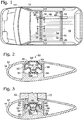
- Fig. 1 shows an illustrative vehicle rack crossbar system, generally indicated at 10, mounted to a vehicle 12.
- System 10 includes two crossbars 14 and 16 oriented perpendicular to an elongate axis and direction of travel of vehicle 12.
- crossbars 14 and 16 are substantially rigid.
- crossbars 14 and 16 may be formed from extrusions of one or more metallic materials, such as aluminum or an aluminum alloy.
- Crossbars 14 and 16 are coupled to roof 18 of vehicle 12 by towers 20, 22, 24, and 26. Examples of suitable towers are described in US6010048 and US8393508 . Towers 20, 22, 24, and 26 may alternatively be described as legs or feet.
- Each crossbar includes a lengthwise T-slot or channel, indicated at 30 and 34.
- Each channel has first and second opposing lips 36 and 40 having upper surfaces spaced apart by a generally constant and/or continuous distance.
- the channel may be described as a cavity having a longitudinal opening defined between opposing lips 36 and 40. Opposing lips 36 and 40 may form a partial ceiling of the cavity.
- a cargo-specific rack accessory 44 may be mounted to crossbars 14 and 16 by retention devices 46 and 48, with each retention device having a body and a cleat, as described in Serial No. 13/873,006 for example.
- the bodies of the retention devices may be seated on respective upper surfaces of crossbars 14 and 16, and the cleats may be inserted into the respective channels of the crossbars.
- Crossbars 14 and 16 may each be metal crossbars, with each metal crossbar having a one piece design to provide a rigid and/or secure mounting interface for retention devices 46 and 48.
- Retention devices 46 and 48 may secure accessory 44 to the crossbars by pinching opposing lips 36 and 40 of the respective crossbar between the body and the cleat of the respective retention device.
- An infill of the present disclosure may be disposed in the channel and extend along the length of the channel.
- the infill may have a lower portion seated on a floor portion of the channel.
- the infill may be operable between a flush position, wherein an upper surface of an upper portion of the infill is substantially flush with the upper surface of the crossbar, and a compressed position, wherein the infill is locally compressed in the channel to allow the cleat to enter the channel and secure accessory 44 to the crossbar without removing the infill from the channel.
- Infills of the present disclosure may be described as "leave-in" infills.
- previous infill designs typically required tearing or removal of the infill in order to secure an accessory to the channel.
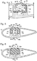
- Fig. 2 shows a cross-section of crossbar 14 and a first exemplary infill, generally indicated at 50, in a flush position, the cross-section being taken along line 2-2 in Fig. 1 .
- Crossbar 14 may have an aerodynamic cross-sectional shape similar or identical to the cross-sectional shape shown in Fig. 5 of US20100308091A1 .
- longitudinal bump 51 positioned on a nose portion of the crossbar may be rounded with a slightly convex forward facing surface and a slightly concave rear facing surface.
- longitudinal channel 30 may have a longitudinal opening.
- the longitudinal opening may have a width and height defined between first and second opposing lips 36 and 40.
- Fig. 2 shows the width of the opening being constant through the height of the opening.
- Fig. 2 shows first and second opposing lips 36 and 40 as having constant thicknesses.
- the opening may have a uniform width.
- edges of first and second opposing lips 36 and 40 defining the width and the height of the opening may extend substantially vertically.
- the edges of first and second opposing lips 36 and 40 may extend substantially perpendicular to the upper (or outer) surface of the crossbar, the upper surface of first and second opposing lips 36 and 40, and/or the lower surface of first and second opposing lips 36 and 40.
- the opening leads to the cavity, which has a generally rectangular shaped cross-section.
- the cavity has a first opposing sidewall 52 connecting a floor portion 54 of the cavity to the first opposing lip 36, and a second opposing sidewall 56 connecting floor portion 54 to second opposing lip 40, with opposing lips 36 and 40 forming the partial ceiling of the cavity.
- infill 50 has a hollow interior and includes a base 58 connected to a cap or plug portion 60 by first and second curved walls 62 and 64, and first and second side panels 66 and 68.
- Base 58 may be seated on floor portion 54, and cap 60 may substantially seal the opening to the cavity between opposing lips 36 and 40.
- side panels 66 and 68 may contact or press upward on opposing lips 36 and 40, and may contact or press outward on opposing side walls 52 and 56.
- cap 60 steps up vertically from side panels 66 and 68 with portions that parallel opposing edges of lips 36 and 40 and side walls 52 and 56.
- An upper surface of cap 60 may be substantially flush with the upper surface of crossbar 14 in a location where retention device 46 (see Fig. 1 ) is not clamped to opposing lips 36 and 40.
- the flush position of infill 50 may be defined as cap 60 substantially filling the opening between opposing lips 36 and 40.
- the width of the opening may be constant through the height of the opening (e.g., from an upper surface of first and second opposing lips 36 and 40 to lower surfaces of first and second opposing lips 36 and 40).
- Plug portion 60 may be dimensioned to correspond to the dimensions of the opening (e.g., a height of plug portion 60 may substantially match the height of the opening, and a width of plug portion 60 may substantially match or be slightly narrower than the width of the opening).
- cap portion 60 forms a first recessed angle with first opposing side panel 66, and a second recessed angle with the second opposing side panel 68, with the first and second recessed angles contacting edges of first and second opposing lips 36 and 40.
- the edges of first and second opposing lips 36 and 40 may be metallic edges.
- the first recessed angle contacting a metallic edge of opposing lip 36 and the second recessed angle contacting a metallic edge of opposing lip 40 may provide a synergistic combination of components and relationships thereof in reducing wind noise.
- Fig. 3 shows a cross-section of crossbar 14 and infill 50 in a compressed position, the cross-section being taken along the line 3-3 in Fig. 1 .
- a cleat 70 and a body 72 of retention device 46 are shown clamping opposing lips 36 and 40. As shown, insertion of cleat 70 into the cavity pushes cap 60 away from the opening and toward floor portion 54, resulting in the compressed position of infill 50.
- side panels 66 and 68 When moving from the flush position to the compressed position, side panels 66 and 68 may be compressed toward floor portion 54, and curved walls 62 and 64 may further flex, bend, or be compressed toward floor portion 54.
- Moving from the flush position to the compressed position may involve side panels 66 and 68 sliding downward on opposing surfaces of side walls 52 and 56.
- cleat 70 may contact cap 60 but not side panels 66 and 68. In other embodiments, cleat 70 may contact cap 60 and side panels 66 and 68 in the compressed position.
- side panel 66 may contact or press against curved wall 62, and side panel 68 may contact or press against curved wall 64. In other embodiments, side panel 66 and/or side panel 68 may not contact or press against respective curved walls 62 and 64 in the compressed position.
- infill 50 When cleat 70 is removed from the opening, infill 50 may return to the flush position shown in Fig. 2 , thus infill 50 may be described as a resilient infill. Infill 50 may be formed from an extrusion of rubber, plastic, any other suitable resilient material, or combination thereof.
- Fig. 4 shows a cross-section of a second exemplary infill, generally indicated at 80, disposed in the cavity of crossbar 14.
- Infill 80 drawn in solid lines corresponds to a flush position of infill 80 and to a cross-section of infill 80 taken along the line 2-2 in Fig. 1 .
- Infill 80 drawn in dash double dot lines corresponds to a compressed position of infill 80 and to a cross-section of infill 80 taken along the line 3-3 in Fig. 1 .
- Retention device 46 has been removed from Fig. 4 to simplify the drawing.
- infill 80 is horizontally asymmetric in the flush and compressed positions.
- infill 80 includes a base 82 having first and second end portions 82a and 82b, an upper portion 84 having first and second end portions 84a and 84b, and a side panel 86 connecting second end portion 82b of base 82 to second end portion 84b of upper portion 84.
- Base 82 may be seated on floor portion 54.
- First end portion 82a may contact or press against side wall 52
- second end portion 82b may contact or press against side wall 56.
- Side panel 86 may extend along, contact, and/or press against side wall 56.
- Upper portion 84 may be cantilevered over base 82 in a region corresponding to the longitudinal opening, and a cap or plug portion 84c of upper portion 84 may substantially fill the longitudinal opening in the flush position.
- infill 80 may be compressed in the cavity in the flush position away from an equilibrium position of infill 80, resulting in first end portion 84a pressing upward on lip 36.
- a cantilevered member may be defined as a member (e.g., upper portion 84) supported at only one end portion (e.g., second end portion 84b) and carrying a load on the other end portion (e.g., first end portion 84a) or along the length of the member (e.g., along a length of upper portion 84 from first end portion 84a to second end portion 84b).
- Upper portion 84 may be described as being connected to and/or cantilevered over base 82 by a resilient and/or living hinge.
- the living hinge may include a juncture of second end portion 84b to side panel 86, and/or a juncture of second end portion 82b to side panel 86. Thicknesses of base 82, side panel 86, and upper portion 84 may be varied to improve the resiliency, restorative force, and/or flexibility of the living hinge.
- plug portion 84c of infill 80 may be dimensioned to correspond to the constant width of the opening through the height of the opening.
- Second end portion 84b may be tensioned or biased toward lip 40.
- infill 80 may be structured to provide for a gap 88 between the lower surface of lip 40 and an upper surface of second end portion 84b.
- the upper surface of second end portion 84b may be disposed further from the lower surface of second opposing lip 40 than an upper surface of first end portion 84a is from the lower surface of first opposing lip 36 in the flush position.
- a step between the upper surface of second end portion 84b and an upper surface of cap portion 84c may have a greater height than a step between the upper surface of first end portion 84a and the upper surface of cap portion 84c.
- infill 80 is operable between the flush position that substantially fills the longitudinal opening of crossbar 14, and the compressed position inside the cavity that may allow for cleat 70 (see Fig. 3 ) to pass through the longitudinal opening into the cavity and clamp opposing lips 36 and 40.
- Cleat 70 may press against cap portion 84c, resulting in upper portion 84 pivoting away from the longitudinal opening.
- first end portion 84a may pivot toward floor portion 54, which may cause side panel 86 to flex away from side wall 56.
- an upper portion of side panel 86 flexes further away from side wall 56 than a lower portion of side panel 86 as infill 80 moves from the flush position to the compressed position.
- first end portion 84a of upper portion 84 may be closer to floor portion 54 than second end portion 84b is to floor portion 54. In the compressed position, first end portion 84a may contact base 82 distal from first end portion 82a of base 82.
- Infill 80 may be described as a horizontally asymmetric infill having a substantially C-shaped cross-section, with a mouth of the C-shaped cross-section facing first opposing side wall 52 of the channel and being opposite side panel 86. Movement of infill 80 from the flush position to the compressed position may narrow a width of the mouth (e.g. a distance between first end portion 84a of upper portion 84 and first end portion 82a of base 82), and movement of infill 80 from the compressed position to the flush position may widen the width of the mouth. Side panel 86 may contact second opposing side wall 56 when upper portion 84 substantially seals the longitudinal opening of the cavity. Side panel 86 may locally pivot away from (or bend away from) second opposing side wall 56 when upper portion 84 is locally depressed toward floor portion 54.
- side panel 86 may not contact second opposing side wall 56, and/or side panel may be disposed closer to first opposing side wall 52 and second opposing side wall 56.
- infill 80 may be reversed in the channel such that the mouth of the C-shaped cross-section faces second opposing side wall 56 and faces away from the direction of travel of the vehicle (see Fig. 1 ).
- infill 80 may return or flex back to the flush position, thus infill 80 may be described as a resilient infill.
- Infill 80 may be formed from an extrusion of rubber, plastic, or any other suitable resilient material.
- cap portion 84c vertically projects from first and second end portions 84a and 84b to substantially fill the longitudinal opening in the flush position.
- opposing lips 36 and 40 may have tapered portions, which taper toward one another, in which case, upper portion 84 may include first and second opposing ramp portions that conform to these tapered portions.
- the tapered portions may include concavely curved surfaces and the ramp portions may include convexly curved surfaces configured to contact or press against the concavely curved surfaces of the tapered portions.
- Fig. 5 shows a cross-section of a third exemplary infill, generally indicated at 100, disposed in the cavity of crossbar 14 (shown here with opposing lips 36 and 40 including the previously mentioned tapered portions with concavely curved surfaces).
- Infill 100 drawn in solid lines corresponds to a flush position of infill 100 and to a cross-section of infill 100 taken along the line 2-2 in Fig. 1 .
- Infill 100 drawn in dash double dot lines corresponds to a compressed position of infill 100 and to a cross-section of infill 100 taken along the line 3-3 in Fig. 1 .
- Retention device 46 has been removed from Fig. 5 to simplify the drawing.
- Infill 100 may be made of open-celled foam and/or closed-celled foam.
- infill 100 may be made of an extrusion of open-celled foam, closed-celled foam, or a combination thereof.
- the foam of infill 100 may have a density in a range of 0.8 to 10.0 pounds per cubic foot (PCF), and an indentation load deflection (IFD) in a range of 5-95%.
- PCF pounds per cubic foot
- IFD indentation load deflection
- infill 100 has a generally U-shaped cross-section with a central upper portion 102 connected to respective top portions of first and second outer walls 104 and 106.
- Central upper portion 102 substantially fills and/or seals the longitudinal opening between opposing lips 36 and 40 in the flush position.
- Respective bottom portions of outer walls 104 and 106 are seated on or press against floor portion 54 of the channel.
- An upper surface of central upper portion 102 is continuously convexly curved and contacts or presses against tapered portions 36a and 40a of opposing lips 36 and 40.
- Portions of infill 100 contacting tapered portions 36a and 40a of opposing lips 36 and 40 may be described as first and second opposing ramp portions that are convexly curved.
- convexly curved portions of upper portion 102 contact and may conform to concavely curved surfaces of tapered portions 36a and 40a.
- upper portion 102 may include a plug portion similar to plug portion 60 (see Fig. 2 ), and first and second opposing lips 36 and 40 may define an opening similar to the opening shown in Fig. 2 .
- the plug portion of upper portion 102 may be dimensioned to correspond to a constant width of the opening through a height of the opening.
- Clamping opposing lips 36 and 40 may involve inserting cleat 70 (see Fig. 3 ) into the longitudinal opening, which may push down (or move) infill 100 to the compressed position.
- Moving infill 100 from the flush position to the compressed position may involve the top portions of outer walls 104 and 106 sliding downward against respective first and second opposing side walls 52 and 56 of the channel.
- Moving infill 100 from the flush position to the compressed position may cause a lower surface 102a of central upper portion 102 to flex from being concavely curved to being substantially flat to being convexly curved.
- Moving infill 100 from the flush position to the compressed position may involve inner surfaces 104a and 106a of outer walls 104 and 106 bulging toward the center of the cavity.
- infill 100 may bridge an opening in floor portion 54 defined between a secondary pair of opposing lips 108 and 110, with the opening in floor portion 54 leading to a secondary cavity 112. As shown, infill 100 may not contact opposing lips 108 and 110 in either the flush or compressed positions.
- infill 100 When the cleat is removed from the opening, infill 100 may return to the flush position, thus infill 100 may be described as a resilient infill.
- Fig. 6 shows a cross-section of a fourth exemplary infill, generally indicated at 200, disposed in the cavity of crossbar 14 (shown here with opposing lips 36 and 40 including tapered portions 36a and 40a with concavely curved surfaces).
- Infill 200 drawn in solid lines corresponds to a flush position of infill 200 and to a cross-section of infill 200 taken along the line 2-2 in Fig. 1 .
- Infill 200 drawn in dash double dot lines corresponds to a compressed position of infill 200 and to a cross-section of infill 200 taken along the line 3-3 in Fig. 1 .
- Retention device 46 has been removed from Fig. 6 to simplify the drawing.
- Infill 200 may be made of open-celled foam or closed-celled foam.
- infill 100 may be made of an extrusion of open-celled foam, closed-celled foam, or a combination thereof.
- the foam of infill 200 may have a density in a range of 0.8 to 10.0 pounds per cubic foot (PCF), and an indentation load deflection (IFD) in a range of 5-95%.
- PCF pounds per cubic foot
- IFD indentation load deflection
- infill 200 has a generally D-shaped cross-section with an upper portion 202 connected to a base or lower portion 204.
- Upper portion 202 substantially fills and/or seals the longitudinal opening between opposing lips 36 and 40 in the flush position.
- Base portion 204 is seated on or presses against floor portion 54 of the channel.
- An upper surface of upper portion 202 is continuously convexly curved and contacts or presses against tapered portions 36a and 40a of opposing lips 36 and 40.
- convexly curved portions of upper portion 202 contact and may conform to concavely curved surfaces of tapered portions 36a and 40a, and outer wall surfaces 206 and 208 of infill 200 contact respective first and second opposing side walls 52 and 56 of the channel.
- upper portion 202 may include a plug portion similar to plug portion 60 (see Fig. 2 ), and first and second opposing lips 36 and 40 may define an opening similar to the opening shown in Fig. 2 .
- the plug portion of upper portion 202 may be dimensioned to correspond to a constant width of the opening through a height of the opening.
- Clamping opposing lips 36 and 40 may involve inserting cleat 70 (see Fig. 3 ) into the longitudinal opening, which may push down (or move) infill 200 to the compressed position.
- Moving infill 200 from the flush position to the compressed position may involve the upper portions of outer walls surfaces 206 and 208 of infill 200 sliding downward against respective first and second opposing side walls 52 and 56 of the channel.
- Moving infill 200 from the flush position to the compressed position may cause the upper surface of upper portion 202 to flex from being convexly curved to being substantially flat to possibly being concavely curved.
- Moving infill 200 from the flush position to the compressed position may cause a lower surface of base portion 204 to bulge downward between second pair of opposing lips 108 and 110.
- infill 200 may return to the flush position, thus infill 200 may be described as a resilient infill.
- Fig. 7 shows a fifth example of an infill, generally indicated at 300, disposed in the channel of crossbar 14 in a flush position.
- Infill 300 may include a first component made of a first material having a first compositional characteristic, such as a rigid material having a relatively high rigidity and a relatively low resiliency or elasticity.
- Infill 300 may include a second component made of a second material having a second compositional characteristic, such as a resilient material having a relatively low rigidity and relatively high resiliency or elasticity. The second component may be configured to bias or press the first component upward against the partial ceiling of the channel.
- Infill 300 may include a plurality of infill segments stacked up in the channel, along a majority of the length of the channel or along the entire length of the channel. However, only four infill segments, generally indicated at 300a, 300b, 300c, and 300d, are shown stacked up in the channel in order to simplify the drawing.
- Each infill segment may include an upper portion 302 connected to a biasing device.
- the biasing device may include one or more springs, such as first and second opposing leaf springs 304 and 306.
- First and second opposing leaf springs may be connected to a lower surface of upper portion 302 and bias upper portion 302 toward first and second opposing lips 36 and 40 and the partial ceiling of the channel, which may also involve convexly curved portions of upper portion 302 pressing against concavely curved tapered portions 36a and 40a.
- upper portion 302 may include a plug portion similar to plug portion 60 (see Fig. 2 ), and first and second opposing lips 36 and 40 may define an opening similar to the opening shown in Fig. 2 .
- the plug portion of upper portion 302 may be dimensioned to correspond to a constant width of the opening through a height of the opening.
- Upper portion 302 may be comprised of the first material, such as polypropylene or a hardened elastomeric material.
- First and second leaf springs may be comprised of the second material, such as spring steel or a steel alloy. If upper portion 302 is made of a relatively flexible material, such as rubber, then the upper portion of infill 300 may have a continuous length (e.g., not segmented) extending along a majority of the length of the channel.
- first leaf spring 304 may be connected to upper portion 302 near first opposing side wall 52 of the channel.
- a lower end portion of first leaf spring 304 may press against floor portion 54 near second opposing side wall 56, and curve away from floor portion 54 and toward second opposing lip 40.
- An upper end portion of second leaf spring 306 may be connected to upper portion 302 near second opposing side wall 56 of the channel.
- a lower end portion of first leaf spring 306 may press against floor portion 54 near first opposing side wall 52, and curve away from floor portion 54 and toward first opposing lip 36.
- Upper portion 302 may be dimensioned so that cleat 70 (see Fig. 3 ) inserted into the channel only compresses one of the infill segments to a compressed or depressed position, which may involve compressing the biasing device (e.g., leaf springs 304 and 306) away from an equilibrium position.
- the biasing device e.g., leaf springs 304 and 306
- Infill 300 may be described as a resilient infill.
- a restorative force from the biasing device of that infill segment may push the upper portion of that infill segment back to the flush position as the biasing device moves back toward the equilibrium position.
- Infill 300 may have a horizontally asymmetric cross-section disposed in the cavity.
- a cross-section of infill 300 taken in a vertical plane parallel to the direction of travel of the vehicle may be horizontally asymmetric (e.g., the cross-section may pass through one of the first and second opposing leaf springs but not the other of the first and second opposing leaf springs).
- Fig. 8 shows a cross-section of a sixth exemplary infill, generally indicated at 400, disposed in the cavity of crossbar 14 (shown here with opposing lips 36 and 40 similar to Figs. 2-4 ).
- Infill 400 drawn in solid lines corresponds to a flush position of infill 400 and to a cross-section of infill 400 taken along the line 2-2 in Fig. 1 .
- Infill 400 drawn in dash double dot lines corresponds to a compressed or depressed position of infill 400 and to a cross-section of infill 400 taken along the line 3-3 in Fig. 1 .
- Retention device 46 has been removed from Fig. 8 to simplify the drawing.
- infill 400 between the flush position and depressed position shown and described in relation to Fig. 8 may also describe the movement of one or more of the infill segments of Fig. 7 as those one or more infill segments move between the flush and depressed positions.
- Infill 400 may include a first component (e.g., an upper portion 402) connected to a second component (e.g., a biasing device, such as first and second opposing leaf springs 404 and 406).
- Upper portion 402 substantially fills and/or seals the opening between first and second opposing lips 36 and 40 in the flush position.
- upper portion 402 may include a plug portion dimensioned to correspond to the constant width of the opening through the height of the opening defined between opposing lips 36 and 40, similar to plug portion 60 (see Fig. 2 ) and plug portion 84c (see Fig. 4 ).
- First and second opposing leaf springs 404 and 406 may be connected to a lower surface of upper portion 402 and bias (or push) upper portion 402 toward (or upwardly against) first and second opposing lips 36 and 40 and the partial ceiling of the channel.
- Upper portion 402 may be made of a third material having a third compositional characteristic, such as a material having a relatively high flexibility and a relatively low rigidity, such as rubber.
- First and second leaf springs 404 and 406 may be made of the second material.
- first leaf spring 404 may be connected to upper portion 402 near first opposing side wall 52 of the channel.
- a lower end portion 404b of first leaf spring 404 may press against floor portion 54 near second opposing side wall 56, and curve away from floor portion 54 and toward second opposing lip 40.
- An upper end portion 406a of second leaf spring 406 may be connected to upper portion 402 near second opposing side wall 56 of the channel.
- a lower end portion 406b of first leaf spring 406 may press against floor portion 54 near first opposing side wall 52, and curve away from floor portion 54 and toward first opposing lip 36.
- Inserting cleat 70 (see Fig. 3 ) into the channel may cause the infill 400 to move from the flush position to the depressed position.
- Moving infill 400 from the flush position to the depressed position may involve opposing side surfaces 408 and 410 of upper portion 402 sliding downward along respective first and second opposing side walls 52 and 56.
- Moving infill 400 from the flush position to the depressed position may involve first opposing leaf spring 404 sliding on floor portion 54 toward second opposing side wall 56, and lower end portion 404b contacting or pressing against second opposing side wall 56.
- Moving infill 400 from the flush position to the depressed position may involve second opposing leaf spring 406 sliding on floor portion 54 toward first opposing side wall 52, and lower end portion 406b contacting or pressing against second opposing side wall 52.
- Moving infill 400 from the flush position to the depressed position may involve the first and second components moving away from the opening and toward floor portion 54.
- Infill 400 may be described as a resilient infill.
- moving infill 400 from the flush position to the depressed position may involve loading the biasing device away from an equilibrium position to provide a restorative force that pushes upper portion 402 upward to the flush position when the cleat is removed from the channel.
- Infill 400 may have a horizontally asymmetric cross-section disposed in the cavity.
- Fig. 8 shows a cross-section of infill 400 taken in a vertical plane parallel to the direction of travel of the vehicle, in which the cross-section passes through second opposing leaf spring 406 but not first opposing leaf spring 404.
- Vehicle rack crossbar systems may be described by the following numbered paragraphs:
Landscapes
- Engineering & Computer Science (AREA)
- Mechanical Engineering (AREA)
- Refuge Islands, Traffic Blockers, Or Guard Fence (AREA)
- Load-Engaging Elements For Cranes (AREA)
- Body Structure For Vehicles (AREA)
Claims (18)
- Fahrzeugrahmen-Querträgersystem (10) welches umfasst:einen Querträger (14) (16) mit einer länglichen Öffnung zu einem Kanal (30) (34) mit einer ersten und zweiten gegenüberliegenden Seitenwand (52) (56), die mit einem Bodenbereich (54) verbunden sind, worin die Öffnung eine Weite aufweist, die zwischen einem ersten und zweiten gegenüberliegend Rand (36) (40) definiert ist, worin der Bodenbereich durch die erste und zweite gegenüberliegende Seitenwand (52) (56) mit dem ersten und zweiten gegenüberliegend Rand (36) (40) verbunden ist; undeine Füllung (300), die in dem Kanal (30) (34) angeordnet ist,dadurch gekennzeichnet, dass die Füllung (300) umfasst, eine erste Komponente (302) aus einem ersten Material und eine zweite Komponente aus einem zweiten Material, das verschieden ist von dem ersten Material, worin die zweite Komponente ausgestaltet ist, die erste Komponente (302) nach oben gegen mindestens eine der gegenüberliegenden Ränder (36) (40) zu drücken, worin die Füllung (300) von einer Bündig-Position, bei der die erste Komponente (302) die längliche Öffnung im Wesentlichen ausfüllt, zu einer komprimierten Position, bei der die Komponente (302) auf den Bodenbereich (54) des Kanals (30) (34) heruntergedrückt ist, betrieben werden kann, so dass eine Halterung eines Ladungs-spezifischen Trägerzubehörs den ersten und zweiten gegenüberliegenden Rand (36) (40) klemmen kann.
- Fahrzeugrahmen-Querträgersystem (10) nach Anspruch 1, worin eine obere Fläche der ersten Komponente (302) im Wesentlichen bündig ist mit einer oberen Fläche des Querträgers (14) (16) in der Bündig-Position.
- Fahrzeugrahmen-Querträgersystem (10) nach Anspruch 1, worin das erste Material ein Polymer umfasst, und das zweite Material ein Metall beinhaltet; wahlweise worin die zweite Komponente eine Feder umfasst oder eine erste und zweite gegenüberliegende Blattfeder (304) (306); wahlweise worin ein oberer Bereich der ersten gegenüberliegenden Blattfeder (304) mit der ersten Komponente (302) näher bei der ersten gegenüberliegenden Seitenwand (52) verbunden ist als bei der zweiten gegenüberliegenden Seitenwand (56), und worin ein oberer Bereich der zweiten gegenüberliegenden Blattfeder (306) mit der ersten Komponente (302) näher bei der zweiten gegenüberliegenden Seitenwand (56) verbunden ist als bei der ersten gegenüberliegenden Seitenwand (52); wahlweise worin ein unterer Bereich der ersten gegenüberliegenden Blattfeder (304) gegen den Bodenbereich (54) näher bei der zweiten gegenüberliegenden Seitenwand (56) drückt als bei der ersten gegenüberliegenden Seitenwand (52), und ein unterer Bereich der zweiten gegenüberliegenden Blattfeder (306) gegen den Bodenbereich (54) näher bei der ersten gegenüberliegenden Seitenwand (52) drückt als bei der zweiten gegenüberliegenden Seitenwand (56).
- Fahrzeugrahmen-Querträgersystem (10) welcher umfasst:einen Metall-Querträger (14) (16) mit einer länglichen Öffnung zu einem Hohlraum (30) (34), welcher eine erste und eine zweite gegenüberliegende Seitenwand (52) (56) aufweist, die mit dem Bodenbereich (54) verbunden sind, worin die Öffnung eine Weite und eine Höhe aufweist, die zwischen dem ersten ersten und zweiten gegenüberliegend Rand (36) (40) definiert ist, worin die Weite der Öffnung über die Höhe der Öffnung konstant ist, worin der Bodenbereich (54) mit dem ersten und zweiten gegenüberliegenden Rand (36) (40) durch die erste und zweite gegenüberliegende Seitenwand (52) (56) verbunden ist; undeine Füllung (400), die in dem Hohlraum vorgesehen ist, worin die Füllung (400) mit dem Bodenbereich (54) und der ersten und zweiten gegenüberliegenden Seitenwand (52) (56) in Kontakt steht,dadurch gekennzeichnet, dass die Füllung (400) umfasst, einen Stopfenbereich, der bemessen ist, um der Weite und der Höhe der Öffnung zu entsprechen, worin die Füllung (400) von einer Bündig-Position, bei der der Stopfen-Bereich im Wesentlichen die längliche Öffnung ausfüllt, zu einer komprimierten Position, bei der sich der Stopfenbereich weg von der länglichen Öffnung und auf den Bodenbereich (54) zu bewegt, betrieben werden kann, so dass so dass eine Halterung eines Ladungs-spezifischen Trägerzubehörs den ersten und zweiten gegenüberliegenden Rand (36) (40) klemmen kann.
- Fahrzeugrahmen-Querträgersystem (10) nach Anspruch 4, worin die Füllung (400) einen horizontal asymmetrischen Querschnitt aufweist.
- Fahrzeugrahmen-Querträgersystem (10) nach Anspruch 5, worin eine Basis der Füllung (400) auf dem Bodenbereich (54) sitzt, und der Stopfen-Bereich über die Basis ragt.
- Fahrzeugrahmen-Querträgersystem (10) nach Anspruch 4, worin die Füllung (400) einen horizontal symmetrischen Querschnitt aufweist.
- Fahrzeugrahmen-Querträgersystem (10) nach Anspruch 4, worin sich eine Basis der Füllung (400) auf dem Bodenbereich (54) befindet und mit dem Stopfenbereich Bereich über ein erstes und zweites Seitenpaneel verbunden ist, um ein hohles Inneres auszubilden, worin das erste Seitenpaneel mit der ersten gegenüberliegenden Seitenwand in Kontakt steht und nach oben gegen den ersten gegenüberliegenden Rand (36) drückt, worin das zweite Seitenpaneel mit der zweiten gegenüberliegenden Seitenwand in Kontakt steht und nach oben gegen den zweiten gegenüberliegenden Rand (40) drückt, worin der Stopfen-Bereich vertikal von dem ersten und zweiten Seitenpaneel ansteigt.
- Fahrzeugrahmen-Querträgersystem (10) nach Anspruch 4, worin der Stopfen-Bereich ein erstes Material umfasst, und eine zweite Komponente der Füllung ein zweites Material aufweist, das verschieden ist von dem ersten Material, worin die zweite Komponente ausgestaltet ist, den Stopfen-Bereich in die Bündig-Position zu drücken.
- Fahrzeugrahmen-Querträgersystem (10) welches umfasst:einen Metall-Querträger (14) (16) mit einer länglichen Öffnung zu einem Hohlraum (30) (34) mit einer ersten und zweiten gegenüberliegenden Seitenwand (52) (56), die mit einem Bodenbereich (54) verbunden sind, worin die Öffnung eine Weite und eine Höhe aufweist, die zwischen dem ersten und zweiten gegenüberliegenden Rand (36) (40) definiert ist, worin der Bodenbereich (54) über die erste und zweite gegenüberliegende Seitenwand (52) mit dem ersten und zweiten gegenüberliegenden Rand (36) (40) (56) verbunden ist; undeine Füllung (80),dadurch gekennzeichnet, dass die Füllung (80) einen horizontal asymmetrischen Querschnitt aufweist, der in dem Hohlraum (30) (34) vorgesehen ist, worin die Füllung (80) mit dem Bodenbereich (54) und mindestens einer gegenüberliegenden Seitenwand (52) (56) in Kontakt steht, worin die Füllung (80) von einer Bündig-Position, bei der der obere Bereich (84) der Füllung (80) im Wesentlichen die längliche Öffnung ausfüllt, zu einer komprimierten Position, bei der sich der obere Bereich (84) der Füllung (80) weg von der länglichen Öffnung und auf den Bodenbereich (54) zu bewegt, betrieben werden kann, so dass eine Halterung eines Ladungs-spezifischen Trägerzubehörs den ersten und zweiten gegenüberliegenden Rand (36) (40) klemmen kann.
- Fahrzeugrahmen-Querträgersystem (10) nach Anspruch 10, worin der obere Bereich (84) einen Stopfen-Bereich (84c) umfasst, der vertikal in die längliche Öffnung in der Bündig-Position ansteigt.
- Fahrzeugrahmen-Querträgersystem (10) nach Anspruch 11, worin die Weite der Öffnung durch die Höhe der Öffnung konstant ist, und worin der Stopfen-Bereich (84c) bemessen ist, so dass dieser der Weite und Höhe der Öffnung entspricht.
- Fahrzeugrahmen-Querträgersystem (10) nach Anspruch 12, worin die Füllung (80) eine Basis (82) umfasst, die auf dem Bodenbereich (54) des Hohlraums vorgesehen ist, und worin der Stopfen-Bereich (84) über die Basis (82) vorspringt.
- Fahrzeugrahmen-Querträgersystem (10) nach Anspruch 11, worin der Stopfen-Bereich (84c) ein erstes Material umfasst, und eine zweite Komponente der Füllung (80) ein zweites Material umfasst, das verschieden ist von dem ersten Material, worin die zweite Komponente ausgestaltet ist, den Stopfen-Bereich (84c) in die Bündig-Position zu drücken.
- Fahrzeugrahmen-Querträgersystem (10) nach Anspruch 14, worin die zweite Komponente eine Feder umfasst, die ausgestaltet ist, den Stopfen-Bereich (84c) in die Bündig-Position zu drücken.
- Fahrzeugrahmen-Querträgersystem (10) welcher umfasst:einen Querträger (14) (16) mit einer länglichen Öffnung zu einem Kanal (30) (34) mit einer ersten und zweiten gegenüberliegenden Seitenwand (52) (56), die mit einem Bodenbereich (54) verbunden sind, worin die Öffnung eine Weite aufweist, die zwischen einem ersten und zweiten gegenüberliegenden Rand (36) (40) definiert ist, worin der Bodenbereich mit dem ersten und zweiten gegenüberliegenden Rand (36) (40) über die erste und zweite gegenüberliegende Seitenwand (52) (56) verbunden ist; undeine Füllung (50), die in dem Kanal (30) (34) vorgesehen ist, worin die Füllung (50) eine Basis (58) aufweist, die auf einem Bodenbereich (54) des Kanals des Querträgers (14) (16) sitzt; worin ein erstes Seitenpaneel (62) der Füllung (50), das mit der Basis (58) verbunden ist, mit einer ersten gegenüberliegende Seitenwand (52) des Kanals in Kontakt steht, und nach oben gegen einen ersten gegenüberliegenden Rand (36) des Kanals drückt; und worin ein zweites Seitenpaneel (64) der Füllung (50), das mit der Basis (58) verbunden ist, mit einer zweiten gegenüberliegenden Seitenwand (56) des Kanals in Kontakt steht, und nach oben auf einen zweiten gegenüberliegenden Rand (40) des Kanals drückt;so dass eine Halterung eines Ladungs-spezifischen Trägerzubehörs den ersten und zweiten gegenüberliegenden Rand (36) (40) klemmen kann,dadurch gekennzeichnet, dass die Füllung (50) eine Kappe oder einen Stopfen-Bereich umfasst, der mit den zwei abgewandten Seitenpaneelen (62) (64) verbunden ist und vertikal davon hervortritt, um eine längliche Öffnung des Querträgers auszufüllen.
- Fahrzeugrahmen-Querträgersystem (10) nach Anspruch 16, worin die längliche Öffnung eine Weite aufweist, die zwischen dem ersten und zweiten gegenüberliegenden Rand liegt (36) (40) .
- Fahrzeugrahmen-Querträgersystem (10) nach einem der Ansprüche 16 bis 17, worin die Füllung (50) von einer Bündig-Position bei der die längliche Öffnung im Wesentlichen ausgefüllt ist, zu einer komprimierten Position in dem Kanal komprimierbar ist, so dass eine Halterung eines Ladungs-spezifischen Trägerzubehörs den ersten und zweiten gegenüberliegenden Rand (36) (40) klemmen kann.
Priority Applications (2)
| Application Number | Priority Date | Filing Date | Title |
|---|---|---|---|
| PL13826040T PL2879916T3 (pl) | 2012-07-30 | 2013-07-30 | Wypełnienie rowka teowego belki poprzecznej |
| DE13826040.1T DE13826040T1 (de) | 2012-07-30 | 2013-07-30 | T-nut-füllung für querträger |
Applications Claiming Priority (2)
| Application Number | Priority Date | Filing Date | Title |
|---|---|---|---|
| US201261677427P | 2012-07-30 | 2012-07-30 | |
| PCT/US2013/052785 WO2014022435A1 (en) | 2012-07-30 | 2013-07-30 | Crossbar t-slot infill |
Publications (3)
| Publication Number | Publication Date |
|---|---|
| EP2879916A1 EP2879916A1 (de) | 2015-06-10 |
| EP2879916A4 EP2879916A4 (de) | 2016-04-13 |
| EP2879916B1 true EP2879916B1 (de) | 2018-03-07 |
Family
ID=50028481
Family Applications (1)
| Application Number | Title | Priority Date | Filing Date |
|---|---|---|---|
| EP13826040.1A Active EP2879916B1 (de) | 2012-07-30 | 2013-07-30 | T-nut-füllung für querträger |
Country Status (8)
| Country | Link |
|---|---|
| US (1) | US8925775B2 (de) |
| EP (1) | EP2879916B1 (de) |
| AU (1) | AU2013296576B2 (de) |
| CA (1) | CA2880705A1 (de) |
| DE (1) | DE13826040T1 (de) |
| NZ (1) | NZ705034A (de) |
| PL (1) | PL2879916T3 (de) |
| WO (1) | WO2014022435A1 (de) |
Families Citing this family (12)
| Publication number | Priority date | Publication date | Assignee | Title |
|---|---|---|---|---|
| NZ561809A (en) * | 2007-09-21 | 2009-11-27 | Hubco Automotive Ltd | Resilient infill |
| NZ561811A (en) | 2007-09-21 | 2010-06-25 | Hubco Automotive Ltd | Extendable roof rack |
| NZ571287A (en) | 2008-09-15 | 2011-03-31 | Hubco Automotive Ltd | A bracket and a crossbar assembly for a roof rack |
| EP2844523B1 (de) | 2012-04-30 | 2017-04-26 | Yakima Australia Pty Limited | Haltedock |
| NZ705034A (en) | 2012-07-30 | 2017-04-28 | Yakima Australia Pty Ltd | Crossbar t-slot infill |
| PL3059124T3 (pl) * | 2013-05-13 | 2017-12-29 | Thule Sweden Ab | Belka przenosząca obciążenie |
| US10040403B2 (en) | 2015-06-09 | 2018-08-07 | Yakima Products, Inc. | Crossbar clamp actuator |
| US20160362056A1 (en) * | 2015-06-11 | 2016-12-15 | Cequent Performance Products Inc. | Roof rack crossbar assembly |
| JP6407816B2 (ja) * | 2015-07-23 | 2018-10-17 | 株式会社ファルテック | ルーフレール |
| US10220792B2 (en) | 2016-08-24 | 2019-03-05 | Honda Patents & Technologies North America, Llc | Roof rack crossbar |
| EP3339101B1 (de) * | 2016-12-20 | 2019-02-20 | Thule Sweden AB | Fahrzeuglastträger |
| EP3470271B1 (de) * | 2017-10-16 | 2019-10-02 | Thule Sweden AB | Lastenträger |
Family Cites Families (109)
| Publication number | Priority date | Publication date | Assignee | Title |
|---|---|---|---|---|
| GB1045619A (en) | 1964-10-08 | 1966-10-12 | Victor Rosen | A new or improved roof rack for motor vehicles |
| GB1311367A (en) | 1968-08-03 | 1973-03-28 | Workman F Y | Adjustable frames |
| US3606432A (en) | 1968-12-02 | 1971-09-20 | Robert W Honatzis | Protector strip |
| US3677451A (en) | 1969-12-22 | 1972-07-18 | Oliver John Burland | Supporting bar assembly for vehicle |
| US3858774A (en) | 1973-03-30 | 1975-01-07 | Itt | Vehicle roof carrier |
| US4274570A (en) | 1977-10-27 | 1981-06-23 | Bott John Anthony | Luggage carrier assembly |
| US4264025A (en) | 1979-02-26 | 1981-04-28 | Four Star Corporation | Tiedown bracket with ratchet disc |
| US4245764A (en) | 1979-03-29 | 1981-01-20 | Four Star Corporation | Article carrier having variably positionable cross-rail bracket |
| US4277009A (en) | 1979-05-15 | 1981-07-07 | Bott John Anthony | Permanent luggage carrier adapters with removable primary luggage carriers |
| US4487348A (en) | 1981-10-15 | 1984-12-11 | Four Star Corporation | Adjustable and removable cross rail |
| DE3209912A1 (de) | 1981-12-24 | 1983-10-06 | Opel Adam Ag | Fahrzeugdach, insbesondere kraftfahrzeugdach |
| SE436633B (sv) | 1982-04-21 | 1985-01-14 | Thule Ind Ab | Lasthallare for fordon |
| US4448337A (en) | 1982-05-06 | 1984-05-15 | Masco Corporation | Article carrier |
| AU574669B2 (en) | 1983-03-29 | 1988-07-14 | Unistrut Australia Pty Limited | Vehicle roof rack |
| US4588117A (en) | 1983-04-11 | 1986-05-13 | Bott John Anthony | Cross rail for vehicle luggage carrier |
| SE8305871L (sv) | 1983-10-25 | 1985-04-26 | Odd Hielm | Lasbar lasthallare for biltak |
| FR2569639B1 (fr) | 1984-09-06 | 1988-05-06 | Maby Jacques | Barre porteuse universelle pour voitures avec et sans gouttieres |
| IT8553029V0 (it) | 1985-02-25 | 1985-02-25 | G E V Ricambi S P A | Portacarichi applicabile indistinta mente ad autovetture con e senza gocciolatoi |
| US4586638A (en) | 1985-03-06 | 1986-05-06 | The Shelburne Corporation | Multi-purpose rack for removable mounting to an automobile roof or the like |
| AU95086S (en) | 1985-07-10 | 1987-02-12 | Rola Roof Racks Australia Pty Ltd | Clamping support |
| US4702398A (en) * | 1986-01-24 | 1987-10-27 | Risdon Corporation | Product dispenser with advance/retract-type delivery means |
| DE3637856A1 (de) * | 1986-11-06 | 1988-05-19 | Daimler Benz Ag | Abdeckleiste fuer dachkanaele von kraftwagen |
| US4789145A (en) * | 1986-12-30 | 1988-12-06 | Ingersoll-Rand Company | Vane spring for air motor |
| SE455589B (sv) | 1987-01-12 | 1988-07-25 | Thule Ind Ab | Festanordning for en for ett fordonstak avsedd lastanordning |
| US4757929A (en) | 1987-09-01 | 1988-07-19 | Norman Nelson | Car rack |
| SE459569B (sv) | 1987-11-24 | 1989-07-17 | Thule Ind Ab | Anordning foer uppbaerning av en last |
| US4995538A (en) | 1987-12-04 | 1991-02-26 | Fapa S.P.A. | Motor vehicle roof rack |
| US4877169A (en) | 1988-03-15 | 1989-10-31 | Yakima Products, Inc. | Self-tightening vehicle roof rack |
| FR2632595B1 (fr) | 1988-06-10 | 1992-03-13 | Renault | Pavillon en materiau composite pour vehicule automobile |
| US5207365A (en) | 1988-09-20 | 1993-05-04 | Bott John Anthony | Article carrier |
| US5025967A (en) | 1989-05-05 | 1991-06-25 | Huron/St. Clair Incorporated | Snap-together luggage carrier slat |
| WO1991010581A1 (en) | 1990-01-10 | 1991-07-25 | Goodcart Pty. Limited | Vehicle roof rack |
| US5205453A (en) | 1990-08-01 | 1993-04-27 | Masco Industries, Inc. | Locking mechanism for automobile luggage racks |
| US5226634A (en) * | 1990-08-31 | 1993-07-13 | Amp Incorporated | Platform spring |
| US5203483A (en) | 1990-11-06 | 1993-04-20 | John A. Bott | Vehicle article carrier |
| DE4108059A1 (de) | 1991-03-13 | 1992-09-17 | Votex Gmbh | Querschnittsform eines quertraegers an einem dachgepaecktraeger eines fahrzeugs |
| US5257710A (en) | 1991-09-17 | 1993-11-02 | Fetovu Proprietary Limited | Vehicle roof rack |
| US5314104A (en) | 1991-09-26 | 1994-05-24 | Douglas Lee | Auto mount for bicycle rack |
| US5201487A (en) | 1992-04-17 | 1993-04-13 | Epplett Richard E | Vehicular rooftop rail mount-to-gutter mount adaptor system |
| SE9201975L (sv) | 1992-06-26 | 1993-06-21 | Mont Blanc Ind Ab | Lastbaerare foer fordon |
| SE470433B (sv) | 1992-08-06 | 1994-03-07 | Holmbergs Fab Ab Brdr | Anordning för justerbar infästning av ett band |
| US5282562A (en) | 1992-11-04 | 1994-02-01 | Stephane Legault | Vehicle roof-top support rack with permanent attachment bases |
| SE505632C2 (sv) | 1993-04-22 | 1997-09-22 | Saab Automobile | Taklastbäranordning för fordon |
| US5282560A (en) | 1993-04-26 | 1994-02-01 | Ford Motor Company | Luggage rack with wind noise reducer |
| FR2707938B1 (fr) | 1993-07-22 | 1995-09-22 | Matra Automobile | Porte-bagages pour véhicule automobile. |
| WO1995007196A1 (en) | 1993-09-10 | 1995-03-16 | Mascotech Accessories, Inc. | Vehicular rack slat securance |
| US5443190A (en) | 1993-09-14 | 1995-08-22 | Jac Products, Inc. | Truck bed support rails |
| DE4334331A1 (de) | 1993-10-08 | 1995-04-13 | Happich Gmbh Gebr | Querträger für Dachlasten an einem mit einer Dachreling ausgestatteten Kraftwagen |
| US5474218A (en) | 1994-07-25 | 1995-12-12 | Chrysler Corporation | Article carrier |
| GB2303344A (en) | 1995-07-20 | 1997-02-19 | Keith White | Vehicle roof rack |
| GB2314059B (en) | 1996-06-12 | 2000-09-06 | Jac Products Inc | Load bar for automobile luggage carrier |
| US5875947A (en) | 1996-10-21 | 1999-03-02 | Industri Ab Thule | Centralized handled bicycle fork anchor |
| JPH10250488A (ja) | 1997-03-07 | 1998-09-22 | Napolex Co | 自動車用ルーフラック |
| CA2234000C (en) | 1997-04-03 | 2005-10-04 | Decoma International Inc. | Article carrier assembly having a cross rail assembly longitudinally adjustable from one side of a motor vehicle |
| US6010048A (en) | 1997-07-09 | 2000-01-04 | Yakima Products | Roof rack with quick release tower assembly |
| US5984155A (en) | 1997-12-29 | 1999-11-16 | Sportrack Llc | Utility bar assemblies for a roof rack |
| US6102265A (en) | 1998-02-18 | 2000-08-15 | Sportrack Llc | Article carrier assembly for a vehicle roof |
| CA2232829A1 (en) | 1998-03-23 | 1999-09-23 | Michael Moliner | Attachment mechanisms for securing utility racks to vehicles |
| WO1999054168A1 (en) * | 1998-04-22 | 1999-10-28 | Hubco Industries Limited | Roof rack or load carrier |
| FR2780007B1 (fr) * | 1998-06-19 | 2000-09-08 | Automaxi Ind Sa | Jonc adapte a recouvrir la rainure longitudinale d'une barre de toit |
| US6739487B2 (en) | 1999-03-01 | 2004-05-25 | Thule Sweden Ab | Vertically engageable carrier foot |
| US6279802B1 (en) | 1999-03-25 | 2001-08-28 | Jac Products, Inc. | Vehicle article carrier having wind noise reducing cross bar |
| DE19919852C2 (de) * | 1999-04-30 | 2003-01-16 | Raymond A & Cie | Abdeckvorrichtung für Montageaussparungen an Dachleisten von Autokarosserien |
| US6105841A (en) | 1999-06-15 | 2000-08-22 | Jac Products, Inc. | Vehicle article carrier and clamping cross bar therefor |
| EP1077160B1 (de) | 1999-07-16 | 2001-05-02 | Fabio Pedrini | Gepäckträger für ein Kraftfahrzeugdach |
| JP3601367B2 (ja) * | 1999-08-26 | 2004-12-15 | トヨタ自動車株式会社 | 風切り音低減構造 |
| FR2816564B1 (fr) | 2000-11-14 | 2003-02-28 | Wagon Automotive Snc | Barre de galerie pour vehicules automobiles, destinee a etre montee sur des longerons non paralleles |
| US6779696B2 (en) | 2001-10-05 | 2004-08-24 | Jac Products, Inc. | Article carrier having single sided releasable cross bar |
| DE60205336T2 (de) | 2002-02-28 | 2006-04-06 | Chiu-Kuei Yuanli Wang | Verstellbare Dachträgervorrichtung für Fahrzeuge |
| SE0201971L (sv) | 2002-06-26 | 2003-05-13 | Mont Blanc Ind Ab | Anordning vid en för takmontage avsedd lastäbrare till fordon |
| NZ520043A (en) | 2002-08-09 | 2005-04-29 | Hubco Ind Ltd | Vehicle roof rack |
| US6796471B2 (en) | 2002-10-22 | 2004-09-28 | Jac Products, Inc. | Vehicle article carrier having a simplified locking mechanism |
| US6722541B1 (en) | 2002-10-22 | 2004-04-20 | Jac Products Inc. | Article carrier for a truck bed |
| JP4239562B2 (ja) | 2002-11-14 | 2009-03-18 | アイシン精機株式会社 | ルーフラック |
| US20040118886A1 (en) | 2002-12-19 | 2004-06-24 | David Mirshafiee | Apparatus and methods for securing a crossbar to a roof rack |
| US6827531B2 (en) | 2003-01-03 | 2004-12-07 | Nissan Technical Center North America, Inc. | Track slot fastener |
| US6905053B2 (en) | 2003-01-10 | 2005-06-14 | Watermark Paddlesports, Inc. | Rack tower |
| AU2003231688A1 (en) | 2003-01-31 | 2004-08-19 | Roof Rack Industries Pty Ltd | Rail Bar Roof Rack |
| US6845893B2 (en) | 2003-02-25 | 2005-01-25 | Whelen Engineering Company, Inc. | Mounting foot assembly for lightbar |
| US6845922B2 (en) * | 2003-06-10 | 2005-01-25 | Continental Afa Dispensing Company | Child resistant indexing nozzle for a trigger sprayer |
| SE525573C2 (sv) | 2003-10-13 | 2005-03-15 | Thule Sweden Ab | Lastbärarfot |
| US8104651B2 (en) | 2003-10-20 | 2012-01-31 | Cequent Performance Products, Inc. | Vehicle roof rack end support |
| US7182233B1 (en) | 2003-11-07 | 2007-02-27 | Topline Mfg. Inc. | Universal platform system for holding accessories on the roof of a wheeled vehicle |
| US7328824B2 (en) | 2004-05-18 | 2008-02-12 | Yakima Products, Inc. | Crossbar tower assembly for a vehicle rack |
| DE102004044159A1 (de) * | 2004-09-13 | 2006-03-16 | Arvinmeritor Gmbh | Verbundbauteil, insbesondere Karosserieanbauteil für ein Fahrzeug, und Verfahren zum Herstellen eines solchen Verbundbauteils |
| US20060273123A1 (en) | 2004-09-27 | 2006-12-07 | Settelmayer Joseph J | Rack tower assemblies and rack systems |
| US7721925B1 (en) | 2004-10-28 | 2010-05-25 | Graffy Thomas F | Universal removable roof rack mounting system |
| KR100598855B1 (ko) * | 2005-01-20 | 2006-07-11 | 기아자동차주식회사 | 루프랙 장착장치 |
| ATE391637T1 (de) | 2005-02-04 | 2008-04-15 | Thule Sweden Ab | Lastträger für feste dachreling |
| US6997657B1 (en) | 2005-04-08 | 2006-02-14 | Sportrack Llc | Stanchion and cross rail assembly |
| FR2884198B3 (fr) | 2005-04-12 | 2008-11-07 | Scambia Ind Dev Ag | Barre pour etre fixee sur un toit d'un vehicule automobile |
| DE202005007566U1 (de) | 2005-05-13 | 2005-07-14 | Süddeutsche Aluminium Manufaktur GmbH | Dachgepäckträger-Tragholm mit Seitenaussparungen |
| JP2009506921A (ja) | 2005-08-15 | 2009-02-19 | スーリー, インク. | 自転車フォークアセンブリを固定するロードキャリア |
| AU2006100386A4 (en) * | 2006-04-04 | 2006-06-08 | Hubco Automotive Limited | Roof rack crossbar |
| US8028875B2 (en) * | 2006-10-26 | 2011-10-04 | Jac Products, Inc. | Vehicle article carrier having swing in place cross bars |
| NZ561809A (en) | 2007-09-21 | 2009-11-27 | Hubco Automotive Ltd | Resilient infill |
| NZ561811A (en) | 2007-09-21 | 2010-06-25 | Hubco Automotive Ltd | Extendable roof rack |
| NZ561860A (en) | 2007-09-24 | 2010-04-30 | Hubco Automotive Ltd | Versatile leg for a roof rack |
| US20090159624A1 (en) * | 2007-12-20 | 2009-06-25 | Gm Global Technology Operations, Inc. | Roof rack features enabled by active materials |
| US8210407B2 (en) | 2008-06-23 | 2012-07-03 | Yakima Products, Inc. | Bicycle carrier with fork mount and universal crossbar clamp |
| AU2009262302A1 (en) | 2008-06-23 | 2009-12-30 | Yakima Products, Inc. | Rack tower for securing crossbars on top of a vehicle |
| NZ571287A (en) * | 2008-09-15 | 2011-03-31 | Hubco Automotive Ltd | A bracket and a crossbar assembly for a roof rack |
| CN101559738B (zh) | 2009-03-12 | 2011-09-28 | 宁波纽特汽车配件有限公司 | 车顶架 |
| CN101559737B (zh) | 2009-03-12 | 2011-01-05 | 宁波纽特汽车配件有限公司 | 车顶架的调节结构 |
| NZ581567A (en) | 2009-12-01 | 2011-03-31 | Hubco Automotive Ltd | A connection assembly that links a vehicle roof rack to a roof rack accessory |
| CN203888717U (zh) | 2011-09-13 | 2014-10-22 | 胡布柯汽车有限公司 | 自行车车叉固定装置 |
| EP2844523B1 (de) | 2012-04-30 | 2017-04-26 | Yakima Australia Pty Limited | Haltedock |
| DE102012014696B4 (de) * | 2012-07-25 | 2014-02-13 | Audi Ag | Dachträger für ein Kraftfahrzeug, Verfahren zum Betreiben eines Steuergeräts eines Kraftfahrzeugs sowie entsprechendes Steuergerät |
| NZ705034A (en) | 2012-07-30 | 2017-04-28 | Yakima Australia Pty Ltd | Crossbar t-slot infill |
-
2013
- 2013-07-30 NZ NZ705034A patent/NZ705034A/en unknown
- 2013-07-30 PL PL13826040T patent/PL2879916T3/pl unknown
- 2013-07-30 EP EP13826040.1A patent/EP2879916B1/de active Active
- 2013-07-30 US US13/954,897 patent/US8925775B2/en active Active
- 2013-07-30 CA CA2880705A patent/CA2880705A1/en not_active Abandoned
- 2013-07-30 AU AU2013296576A patent/AU2013296576B2/en active Active
- 2013-07-30 WO PCT/US2013/052785 patent/WO2014022435A1/en active Application Filing
- 2013-07-30 DE DE13826040.1T patent/DE13826040T1/de active Pending
Non-Patent Citations (1)
| Title |
|---|
| None * |
Also Published As
| Publication number | Publication date |
|---|---|
| WO2014022435A1 (en) | 2014-02-06 |
| AU2013296576B2 (en) | 2017-02-23 |
| NZ705034A (en) | 2017-04-28 |
| CA2880705A1 (en) | 2014-02-06 |
| AU2013296576A1 (en) | 2015-03-05 |
| EP2879916A1 (de) | 2015-06-10 |
| US8925775B2 (en) | 2015-01-06 |
| US20140158728A1 (en) | 2014-06-12 |
| EP2879916A4 (de) | 2016-04-13 |
| DE13826040T1 (de) | 2017-05-18 |
| PL2879916T3 (pl) | 2018-07-31 |
Similar Documents
| Publication | Publication Date | Title |
|---|---|---|
| EP2879916B1 (de) | T-nut-füllung für querträger | |
| US8544707B2 (en) | Resilient infill | |
| AU2016276603B2 (en) | Slotted crossbar | |
| CN100509487C (zh) | 模制件连接结构、模制件连接夹及模制件 | |
| CN107415843B (zh) | 承重条 | |
| US9434242B2 (en) | Door trim assembly | |
| US10688936B2 (en) | Roof rail for vehicles | |
| EP1503441A3 (de) | Dichtung aus Gummi für einen Brennstoffzellenseparator | |
| CN107956771A (zh) | 具有浮动支承件的夹子 | |
| KR101251132B1 (ko) | 개구 밀폐용 캡 및 이를 포함하는 차량용 루프 캐리어의 사이드 바 조립체 | |
| CN110049900A (zh) | 车辆负荷承载器 | |
| EP3065975B1 (de) | Dachträgereinrichtung und sicherungeinrichtung für eine dachträgereinrichtung | |
| JP6298778B2 (ja) | エンドキャップ及びモールディング | |
| CN217396473U (zh) | 安全带滑动组件和车辆 | |
| US20140097325A1 (en) | Portable electronic device mounting system | |
| CN1489531A (zh) | 密封、修饰和精整条带 | |
| CN210102637U (zh) | 一种卡接固定的滚轴输送滑道 | |
| US20190176716A1 (en) | Apparatus, a vehicle and a method | |
| EP3065961B1 (de) | Profildraht und verfahren zur herstellung eines profildrahtes | |
| CN2866244Y (zh) | 货车用遮蔽装置 |
Legal Events
| Date | Code | Title | Description |
|---|---|---|---|
| PUAI | Public reference made under article 153(3) epc to a published international application that has entered the european phase |
Free format text: ORIGINAL CODE: 0009012 |
|
| 17P | Request for examination filed |
Effective date: 20150224 |
|
| AK | Designated contracting states |
Kind code of ref document: A1 Designated state(s): AL AT BE BG CH CY CZ DE DK EE ES FI FR GB GR HR HU IE IS IT LI LT LU LV MC MK MT NL NO PL PT RO RS SE SI SK SM TR |
|
| AX | Request for extension of the european patent |
Extension state: BA ME |
|
| RIN1 | Information on inventor provided before grant (corrected) |
Inventor name: CONDON, DAVE Inventor name: SAUTTER, CHRIS |
|
| DAX | Request for extension of the european patent (deleted) | ||
| RA4 | Supplementary search report drawn up and despatched (corrected) |
Effective date: 20160315 |
|
| RAP1 | Party data changed (applicant data changed or rights of an application transferred) |
Owner name: YAKIMA AUSTRALIA PTY LIMITED |
|
| RIC1 | Information provided on ipc code assigned before grant |
Ipc: B60R 9/04 20060101AFI20160309BHEP |
|
| RAP1 | Party data changed (applicant data changed or rights of an application transferred) |
Owner name: YAKIMA AUSTRALIA PTY LIMITED |
|
| REG | Reference to a national code |
Ref country code: FR Ref legal event code: EL |
|
| 17Q | First examination report despatched |
Effective date: 20170331 |
|
| REG | Reference to a national code |
Ref country code: DE Ref legal event code: R210 Ref document number: 602013034183 Country of ref document: DE Ref country code: DE Ref legal event code: R210 |
|
| GRAP | Despatch of communication of intention to grant a patent |
Free format text: ORIGINAL CODE: EPIDOSNIGR1 |
|
| INTG | Intention to grant announced |
Effective date: 20170927 |
|
| RIN1 | Information on inventor provided before grant (corrected) |
Inventor name: SAUTTER, CHRIS Inventor name: CONDON, DAVE |
|
| GRAS | Grant fee paid |
Free format text: ORIGINAL CODE: EPIDOSNIGR3 |
|
| GRAA | (expected) grant |
Free format text: ORIGINAL CODE: 0009210 |
|
| REG | Reference to a national code |
Ref country code: DE Ref legal event code: R082 Ref document number: 602013034183 Country of ref document: DE Representative=s name: BECKER-KURIG-STRAUS PATENTANWAELTE PARTNERSCHA, DE Ref country code: DE Ref legal event code: R082 Ref document number: 602013034183 Country of ref document: DE Ref country code: DE Ref legal event code: R082 Ref document number: 602013034183 Country of ref document: DE Representative=s name: BECKER, KURIG, STRAUS, DE Ref country code: DE Ref legal event code: R082 Ref document number: 602013034183 Country of ref document: DE Representative=s name: 2K PATENT- UND RECHTSANWAELTE PARTNERSCHAFT MB, DE |
|
| REG | Reference to a national code |
Ref country code: DE Ref legal event code: R082 Ref document number: 602013034183 Country of ref document: DE Representative=s name: 2K PATENT- UND RECHTSANWAELTE PARTNERSCHAFT MB, DE |
|
| AK | Designated contracting states |
Kind code of ref document: B1 Designated state(s): AL AT BE BG CH CY CZ DE DK EE ES FI FR GB GR HR HU IE IS IT LI LT LU LV MC MK MT NL NO PL PT RO RS SE SI SK SM TR |
|
| REG | Reference to a national code |
Ref country code: GB Ref legal event code: FG4D |
|
| REG | Reference to a national code |
Ref country code: CH Ref legal event code: EP Ref country code: AT Ref legal event code: REF Ref document number: 976198 Country of ref document: AT Kind code of ref document: T Effective date: 20180315 |
|
| REG | Reference to a national code |
Ref country code: IE Ref legal event code: FG4D |
|
| REG | Reference to a national code |
Ref country code: DE Ref legal event code: R096 Ref document number: 602013034183 Country of ref document: DE |
|
| REG | Reference to a national code |
Ref country code: NL Ref legal event code: MP Effective date: 20180307 |
|
| REG | Reference to a national code |
Ref country code: LT Ref legal event code: MG4D |
|
| PG25 | Lapsed in a contracting state [announced via postgrant information from national office to epo] |
Ref country code: HR Free format text: LAPSE BECAUSE OF FAILURE TO SUBMIT A TRANSLATION OF THE DESCRIPTION OR TO PAY THE FEE WITHIN THE PRESCRIBED TIME-LIMIT Effective date: 20180307 Ref country code: CY Free format text: LAPSE BECAUSE OF FAILURE TO SUBMIT A TRANSLATION OF THE DESCRIPTION OR TO PAY THE FEE WITHIN THE PRESCRIBED TIME-LIMIT Effective date: 20180307 Ref country code: LT Free format text: LAPSE BECAUSE OF FAILURE TO SUBMIT A TRANSLATION OF THE DESCRIPTION OR TO PAY THE FEE WITHIN THE PRESCRIBED TIME-LIMIT Effective date: 20180307 Ref country code: NO Free format text: LAPSE BECAUSE OF FAILURE TO SUBMIT A TRANSLATION OF THE DESCRIPTION OR TO PAY THE FEE WITHIN THE PRESCRIBED TIME-LIMIT Effective date: 20180607 Ref country code: ES Free format text: LAPSE BECAUSE OF FAILURE TO SUBMIT A TRANSLATION OF THE DESCRIPTION OR TO PAY THE FEE WITHIN THE PRESCRIBED TIME-LIMIT Effective date: 20180307 Ref country code: FI Free format text: LAPSE BECAUSE OF FAILURE TO SUBMIT A TRANSLATION OF THE DESCRIPTION OR TO PAY THE FEE WITHIN THE PRESCRIBED TIME-LIMIT Effective date: 20180307 |
|
| REG | Reference to a national code |
Ref country code: AT Ref legal event code: MK05 Ref document number: 976198 Country of ref document: AT Kind code of ref document: T Effective date: 20180307 |
|
| PG25 | Lapsed in a contracting state [announced via postgrant information from national office to epo] |
Ref country code: SE Free format text: LAPSE BECAUSE OF FAILURE TO SUBMIT A TRANSLATION OF THE DESCRIPTION OR TO PAY THE FEE WITHIN THE PRESCRIBED TIME-LIMIT Effective date: 20180307 Ref country code: LV Free format text: LAPSE BECAUSE OF FAILURE TO SUBMIT A TRANSLATION OF THE DESCRIPTION OR TO PAY THE FEE WITHIN THE PRESCRIBED TIME-LIMIT Effective date: 20180307 Ref country code: GR Free format text: LAPSE BECAUSE OF FAILURE TO SUBMIT A TRANSLATION OF THE DESCRIPTION OR TO PAY THE FEE WITHIN THE PRESCRIBED TIME-LIMIT Effective date: 20180608 Ref country code: RS Free format text: LAPSE BECAUSE OF FAILURE TO SUBMIT A TRANSLATION OF THE DESCRIPTION OR TO PAY THE FEE WITHIN THE PRESCRIBED TIME-LIMIT Effective date: 20180307 Ref country code: BG Free format text: LAPSE BECAUSE OF FAILURE TO SUBMIT A TRANSLATION OF THE DESCRIPTION OR TO PAY THE FEE WITHIN THE PRESCRIBED TIME-LIMIT Effective date: 20180607 |
|
| PG25 | Lapsed in a contracting state [announced via postgrant information from national office to epo] |
Ref country code: AL Free format text: LAPSE BECAUSE OF FAILURE TO SUBMIT A TRANSLATION OF THE DESCRIPTION OR TO PAY THE FEE WITHIN THE PRESCRIBED TIME-LIMIT Effective date: 20180307 Ref country code: EE Free format text: LAPSE BECAUSE OF FAILURE TO SUBMIT A TRANSLATION OF THE DESCRIPTION OR TO PAY THE FEE WITHIN THE PRESCRIBED TIME-LIMIT Effective date: 20180307 Ref country code: IT Free format text: LAPSE BECAUSE OF FAILURE TO SUBMIT A TRANSLATION OF THE DESCRIPTION OR TO PAY THE FEE WITHIN THE PRESCRIBED TIME-LIMIT Effective date: 20180307 Ref country code: NL Free format text: LAPSE BECAUSE OF FAILURE TO SUBMIT A TRANSLATION OF THE DESCRIPTION OR TO PAY THE FEE WITHIN THE PRESCRIBED TIME-LIMIT Effective date: 20180307 Ref country code: RO Free format text: LAPSE BECAUSE OF FAILURE TO SUBMIT A TRANSLATION OF THE DESCRIPTION OR TO PAY THE FEE WITHIN THE PRESCRIBED TIME-LIMIT Effective date: 20180307 |
|
| PG25 | Lapsed in a contracting state [announced via postgrant information from national office to epo] |
Ref country code: SK Free format text: LAPSE BECAUSE OF FAILURE TO SUBMIT A TRANSLATION OF THE DESCRIPTION OR TO PAY THE FEE WITHIN THE PRESCRIBED TIME-LIMIT Effective date: 20180307 Ref country code: SM Free format text: LAPSE BECAUSE OF FAILURE TO SUBMIT A TRANSLATION OF THE DESCRIPTION OR TO PAY THE FEE WITHIN THE PRESCRIBED TIME-LIMIT Effective date: 20180307 Ref country code: CZ Free format text: LAPSE BECAUSE OF FAILURE TO SUBMIT A TRANSLATION OF THE DESCRIPTION OR TO PAY THE FEE WITHIN THE PRESCRIBED TIME-LIMIT Effective date: 20180307 Ref country code: AT Free format text: LAPSE BECAUSE OF FAILURE TO SUBMIT A TRANSLATION OF THE DESCRIPTION OR TO PAY THE FEE WITHIN THE PRESCRIBED TIME-LIMIT Effective date: 20180307 |
|
| REG | Reference to a national code |
Ref country code: DE Ref legal event code: R097 Ref document number: 602013034183 Country of ref document: DE |
|
| PG25 | Lapsed in a contracting state [announced via postgrant information from national office to epo] |
Ref country code: PT Free format text: LAPSE BECAUSE OF FAILURE TO SUBMIT A TRANSLATION OF THE DESCRIPTION OR TO PAY THE FEE WITHIN THE PRESCRIBED TIME-LIMIT Effective date: 20180709 |
|
| PLBE | No opposition filed within time limit |
Free format text: ORIGINAL CODE: 0009261 |
|
| STAA | Information on the status of an ep patent application or granted ep patent |
Free format text: STATUS: NO OPPOSITION FILED WITHIN TIME LIMIT |
|
| PG25 | Lapsed in a contracting state [announced via postgrant information from national office to epo] |
Ref country code: DK Free format text: LAPSE BECAUSE OF FAILURE TO SUBMIT A TRANSLATION OF THE DESCRIPTION OR TO PAY THE FEE WITHIN THE PRESCRIBED TIME-LIMIT Effective date: 20180307 |
|
| 26N | No opposition filed |
Effective date: 20181210 |
|
| PG25 | Lapsed in a contracting state [announced via postgrant information from national office to epo] |
Ref country code: SI Free format text: LAPSE BECAUSE OF FAILURE TO SUBMIT A TRANSLATION OF THE DESCRIPTION OR TO PAY THE FEE WITHIN THE PRESCRIBED TIME-LIMIT Effective date: 20180307 |
|
| REG | Reference to a national code |
Ref country code: CH Ref legal event code: PL |
|
| PG25 | Lapsed in a contracting state [announced via postgrant information from national office to epo] |
Ref country code: MC Free format text: LAPSE BECAUSE OF FAILURE TO SUBMIT A TRANSLATION OF THE DESCRIPTION OR TO PAY THE FEE WITHIN THE PRESCRIBED TIME-LIMIT Effective date: 20180307 Ref country code: LU Free format text: LAPSE BECAUSE OF NON-PAYMENT OF DUE FEES Effective date: 20180730 |
|
| REG | Reference to a national code |
Ref country code: BE Ref legal event code: MM Effective date: 20180731 |
|
| PG25 | Lapsed in a contracting state [announced via postgrant information from national office to epo] |
Ref country code: FR Free format text: LAPSE BECAUSE OF NON-PAYMENT OF DUE FEES Effective date: 20180731 Ref country code: CH Free format text: LAPSE BECAUSE OF NON-PAYMENT OF DUE FEES Effective date: 20180731 Ref country code: LI Free format text: LAPSE BECAUSE OF NON-PAYMENT OF DUE FEES Effective date: 20180731 |
|
| REG | Reference to a national code |
Ref country code: IE Ref legal event code: MM4A |
|
| PG25 | Lapsed in a contracting state [announced via postgrant information from national office to epo] |
Ref country code: BE Free format text: LAPSE BECAUSE OF NON-PAYMENT OF DUE FEES Effective date: 20180731 |
|
| PG25 | Lapsed in a contracting state [announced via postgrant information from national office to epo] |
Ref country code: IE Free format text: LAPSE BECAUSE OF NON-PAYMENT OF DUE FEES Effective date: 20180730 |
|
| REG | Reference to a national code |
Ref country code: DE Ref legal event code: R082 Ref document number: 602013034183 Country of ref document: DE Representative=s name: 2K PATENT- UND RECHTSANWAELTE PARTNERSCHAFT MB, DE |
|
| PG25 | Lapsed in a contracting state [announced via postgrant information from national office to epo] |
Ref country code: MT Free format text: LAPSE BECAUSE OF NON-PAYMENT OF DUE FEES Effective date: 20180730 |
|
| PG25 | Lapsed in a contracting state [announced via postgrant information from national office to epo] |
Ref country code: TR Free format text: LAPSE BECAUSE OF FAILURE TO SUBMIT A TRANSLATION OF THE DESCRIPTION OR TO PAY THE FEE WITHIN THE PRESCRIBED TIME-LIMIT Effective date: 20180307 |
|
| PG25 | Lapsed in a contracting state [announced via postgrant information from national office to epo] |
Ref country code: HU Free format text: LAPSE BECAUSE OF FAILURE TO SUBMIT A TRANSLATION OF THE DESCRIPTION OR TO PAY THE FEE WITHIN THE PRESCRIBED TIME-LIMIT; INVALID AB INITIO Effective date: 20130730 |
|
| PG25 | Lapsed in a contracting state [announced via postgrant information from national office to epo] |
Ref country code: MK Free format text: LAPSE BECAUSE OF NON-PAYMENT OF DUE FEES Effective date: 20180307 |
|
| PG25 | Lapsed in a contracting state [announced via postgrant information from national office to epo] |
Ref country code: IS Free format text: LAPSE BECAUSE OF FAILURE TO SUBMIT A TRANSLATION OF THE DESCRIPTION OR TO PAY THE FEE WITHIN THE PRESCRIBED TIME-LIMIT Effective date: 20180707 |
|
| PGFP | Annual fee paid to national office [announced via postgrant information from national office to epo] |
Ref country code: GB Payment date: 20230709 Year of fee payment: 11 |
|
| PGFP | Annual fee paid to national office [announced via postgrant information from national office to epo] |
Ref country code: PL Payment date: 20230713 Year of fee payment: 11 Ref country code: DE Payment date: 20230719 Year of fee payment: 11 |