EP2879815B1 - Richtrolleneinheit - Google Patents
Richtrolleneinheit Download PDFInfo
- Publication number
- EP2879815B1 EP2879815B1 EP13707799.6A EP13707799A EP2879815B1 EP 2879815 B1 EP2879815 B1 EP 2879815B1 EP 13707799 A EP13707799 A EP 13707799A EP 2879815 B1 EP2879815 B1 EP 2879815B1
- Authority
- EP
- European Patent Office
- Prior art keywords
- straightening
- roller unit
- rollers
- unit according
- straightening rollers
- Prior art date
- Legal status (The legal status is an assumption and is not a legal conclusion. Google has not performed a legal analysis and makes no representation as to the accuracy of the status listed.)
- Active
Links
Images


Classifications
-
- B—PERFORMING OPERATIONS; TRANSPORTING
- B21—MECHANICAL METAL-WORKING WITHOUT ESSENTIALLY REMOVING MATERIAL; PUNCHING METAL
- B21D—WORKING OR PROCESSING OF SHEET METAL OR METAL TUBES, RODS OR PROFILES WITHOUT ESSENTIALLY REMOVING MATERIAL; PUNCHING METAL
- B21D3/00—Straightening or restoring form of metal rods, metal tubes, metal profiles, or specific articles made therefrom, whether or not in combination with sheet metal parts
- B21D3/02—Straightening or restoring form of metal rods, metal tubes, metal profiles, or specific articles made therefrom, whether or not in combination with sheet metal parts by rollers
- B21D3/05—Straightening or restoring form of metal rods, metal tubes, metal profiles, or specific articles made therefrom, whether or not in combination with sheet metal parts by rollers arranged on axes rectangular to the path of the work
-
- B—PERFORMING OPERATIONS; TRANSPORTING
- B21—MECHANICAL METAL-WORKING WITHOUT ESSENTIALLY REMOVING MATERIAL; PUNCHING METAL
- B21F—WORKING OR PROCESSING OF METAL WIRE
- B21F1/00—Bending wire other than coiling; Straightening wire
- B21F1/02—Straightening
Definitions
- the invention relates to a straightening roller unit for wire, rod or strip-shaped straightening made of steel, in particular wires, rods, profiles, bands, with pairwise cooperating straightening rollers, which can be adjusted against the straightening and be ventilated by this, wherein the straightening rollers are driven and for the straightening process required feed force is introduced by friction of the straightening rollers in the straightening, and wherein the straightening rollers are coupled with associated drive elements which are drivable by a drive device via a drive power distribution gear.
- the generic EP 1 038 602 A2 teaches a method and apparatus for straightening profiles.
- a set of straightening rollers is provided, the straightening axes are hydraulically adjustable.
- the disadvantage here is that the degree of adjustability is very small, since the straightening rollers are driven parallel to their adjustability by a mechanically fixed gear.
- the DE 1 812 588 A1 shows a roller leveler with driven straightening roller pairs, in which the pairwise opposite straightening rollers can only be adjusted together with respect to the axis of the straightened. An adjustability the straightening rollers relative to each other within a pair is not possible.
- the EP 0 864 387 A1 discloses a straightening roller unit with partially adjustable straightening rollers.
- the adjustable rollers are not driven, so disadvantageously an external drive for the straightening is required.
- the EP 0 689 884 A1 relates to a Rollenrichtmaschine for straightening profiled rolling with adjustable by motorized spindles straightening rollers.
- a disadvantage is the filigree and thus interference-prone structure of the spindles with gear and the relatively small degree of achievable by spindles adjustability of the roller axes.
- the invention aims to provide an improved straightening roller unit, which is preceded example of a wire bending plant and operated with less energy than before and can be used for processing of round or square, rod-shaped or present in winding straightening.
- the invention achieves this in a generic device characterized in that the driving force distribution gear has the straightening rollers associated pairs of upper and lower gears whose axes are coupled as well as the axes of the straightening rollers on swing, the lower gears are mounted in a housing main plate on double bearings whereas the upper gears are supported by the wings and a rotatably mounted bearing housing in the same housing main plate and coupled to the adjusting device.
- the invention thus eliminates the previously used separate drive wheels.
- the feed force needed for the straightening process is rather applied directly over the straightening rollers themselves.
- the straightening rollers are individually or jointly drivable.
- the straightening rollers can be made individually by hand or motorized to the straightening and be ventilated by this.
- all straightening rollers can be adjusted by hand or by means of a motor-driven central adjusting device to the straightening material and can be released from it.
- the straightening rollers can thus be employed individually or motor-driven or jointly manually or motor-driven to the straightening in the context of the invention, depending on Richtgutgeometrie and straightening.
- the processing of the straightened material can be done in a single pass or parallel pass.
- All drive and Anstellvortician are executable by means of a program control device.
- the straightening roller unit shown is intended for straight straightening of elongate straightening material 1, such as wires, rods, profiles, bands, etc.
- the straightening material 1 can have an angular or round cross-section and cut to length or in rod form or winding form.
- a consisting of substantially three interconnected plates 2 ', 2 ", 2"' housing 2 ( Fig. 3 ) receives one or more in the feed direction P successively connected pairs of upper and lower straightening rollers 6, which are arranged on both sides of a Richtgutvorschubebene.
- a mounted on the outside of a housing plate 2 ", eg electric drive device 3 is used to drive a subsequently explained transmission device 4 for distributing the force applied by the drive device 3 feed force to the individual straightening rollers. 6
- a motor-operated Einzelverstell Nurstell Nurs 7 and a manually or motor-operated Primaverstell Nurs 8 are arranged for the straightening rollers 6.
- the engine operation is controlled by a program control device, not shown.
- the housing 2 also serves to protect against dirt and mechanical damage, e.g. through the Richtgut 1.
- the driven by the program control device not shown drive device 3 has a drive sprocket 5 for the distribution gear device 4, which, starting from a Verteilzahnrad 5 'and in a middle housing plate 2'"mounted insects 5" the drive power of the drive gear 5 via a series of meshing gears 4 'on the associated straightening rollers. 6 distributed.
- all straightening rollers 6 are driven.
- the gears 4 ' can be driven individually. Instead of the gears 4 'may for example also be provided belt.
- this distribution gear device 4 is chosen so that the output side arranged upper straightening rollers 6 the requirements of Richtgeometrie and the straightening quality and the feed force can be made independently or together to the Richtgut 1, without losing the Vorschubkraft gleich or to interrupt.
- the straightening rollers 6 are designed as double track guidelines, wherein the lower straightening rollers 6 are mounted in a rotatably mounted in the housing plate 2 'bearing housing 6', whereas the upper bearing housing 6 "with the therein mounted upper straightening rollers 6 via the two wings 14 with the lower bearing housing 6 'is firmly connected, as the Fig. 2 and 5 illustrate.
- the straightening rollers 6 and drive gears 4 'arranged above the straightening material 1 are connected to the adjusting devices 7, 8 via the individual adjusting device 8' and via the bearing housings 6 " to the straightening 1, the gears 4 'are always in engagement.
- the same time serving as feed elements for the straightening 1 straightening rollers 6 can be smooth, but also to increase the friction are performed with profiled surface.
- the profile of the straightening rollers 6 V-shape, as in the embodiment shown, circular shape, ellipse shape or any other shape.
- the upper straightening rollers 6 can also individually by hand or motor in the direction of the arrow P1 in Fig. 1 be made to the straightening material 1 via the adjusting spindle 7.
- the actuator 9 may be formed as a hydraulic cylinder or electric motor, etc.
- the setting values for the various straightening goods of the adjusting devices 7, 8, which are controlled by the program control device, not shown, can be stored in the control device in partial or fully automatic mode, so that they can be quickly restored with frequent change of Richtgutes 1.
- the actuator 9 of the central adjusting device 8 can also be adapted to the requirements of the hand, e.g. be operated by means of a hand crank or motor via manual pushbutton and by means of the parent program control device.
- FIG. 3 Another on the housing 2 based hydraulic actuator 10 ( Fig. 3 ) serves to adjust the straightening rollers 6 transversely to the directional plane in the direction of the arrow P10 in Fig. 3 , also, this actuator 10 may instead of hydraulically actuated for manual or electromotive operation are performed, with its operation can be controlled by the program control device. It also serves to compensate for any torsional stresses occurring in Richtgut 1. Finally, the inlet side and a retraction clamping device 13 is provided for the Richtgut 1.
- Fig. 6 to 8 illustrate the operation of the straightening unit for straightening two wires 11, 12 guided in parallel in double track straightening rollers 6. It is often necessary to feed an odd number of wires to feed a downstream wire bending machine. For this purpose, according to the invention alternately the drive of a pair of straightening rollers 6 are stopped. According to Fig. 7 the wire 11 is directed, whereas the wire 12 is stationary and the associated straightening rollers 6 run in bearings 15 empty. In Fig. 8 the situation is reversed.
- the straightening unit according to the invention is able to hold the straightening material 1 exactly in position, regardless of the number of straightening tracks, and also makes it possible to reverse the feed direction.
- a driving device for threading the Richtgutes 1 can be provided before and / or behind the straightening unit, a driving device, not shown.
- the path of the Richtgutes 1 can be any trajectory, which are superimposed on the necessary for straightening deliveries.
- the straightening roller unit can cover a common straightening diameter range of 3 to 20 mm.
- the diameter range is the straightening rollers 6 usually between 50 and 150 mm.
- the invention is modular in such a way that the input side, depending on the requirements, electric, hydraulic, pneumatic motors and jack drives directly or via gearboxes with fixed or variable transmission, e.g. a manual transmission, can be provided.
Landscapes
- Engineering & Computer Science (AREA)
- Mechanical Engineering (AREA)
- Wire Processing (AREA)
- Metal Rolling (AREA)
Description
- Die Erfindung betrifft eine Richtrolleneinheit für draht-, stab- oder bandförmiges Richtgut aus Stahl, insbesondere Drähte, Stäbe, Profile, Bänder, mit paarweise zusammenwirkenden Richtrollen, die gegen das Richtgut anstellbar und von diesem lüftbar sind, wobei die Richtrollen angetrieben sind und die für den Richtvorgang erforderliche Vorschubkraft durch Reibung der Richtrollen in das Richtgut eingebracht wird, und wobei die Richtrollen mit zugeordneten Antriebselementen gekuppelt sind, die von einer Antriebsvorrichtung über ein Antriebskraft-Verteilgetriebe antreibbar sind.
- Aufgrund der immer höher werdenden Anforderungen an die Energieeffizienz von Maschinen und Anlagen zum Richten von derartigem Richtgut wurde auf dem Gebiet des Rollenrichtens mit Vorschubrollen die Energiebilanz überprüft. Ergebnis dieser Untersuchung ist, daß ein wesentlicher Teil der eingesetzten Energie durch Walz- und Reibungsverluste, verursacht durch die Antriebsräder bzw. Antriebsrollen, verloren geht. Des weiteren ist der Energieanteil zur Beschleunigung dieser Antriebseinheiten aufgrund der Massenträgheit erheblich.
- Die gattungsbildende
EP 1 038 602 A2 lehrt ein Verfahren und eine maschinelle Einrichtung zum Richten von Profilen. Dazu ist eine Garnitur von Richtrollen vorgesehen, deren Richtachsen hydraulisch verstellbar sind. Nachteilig ist hier, daß das Maß der Verstellbarkeit sehr klein ausfällt, da die Richtrollen parallel zu ihrer Verstellbarkeit durch ein mechanisch feststehendes Getriebe angetrieben sind. - Die
DE 1 812 588 A1 zeigt eine Rollenrichtmaschine mit angetriebenen Richtrollenpaaren, bei welchen sich die paarweise gegenüberliegenden Richtrollen nur gemeinsam hinsichtlich der Achse des Richtgutes verstellen lassen. Eine Verstellbarkeit der Richtrollen relativ zueinander innerhalb eines Paares ist nicht möglich. - Die
EP 0 864 387 A1 offenbart eine Richtrolleneinheit mit teilweise verstellbaren Richtrollen. Die verstellbaren Rollen sind jedoch nicht angetrieben, weshalb nachteiligerweise ein externer Antrieb für das Richtgut erforderlich ist. - Die
EP 0 689 884 A1 betrifft eine Rollenrichtmaschine zum Richten von profiliertem Walzgut mit durch motorisch angetriebenen Spindeln verstellbaren Richtrollen. Nachteilig ist der filigrane und dadurch störanfällige Aufbau der Spindeln mit Getriebe sowie das relativ kleine Maß der durch Spindeln erzielbaren Verstellbarkeit der Rollenachsen. - Die Erfindung zielt darauf ab, eine verbesserte Richtrolleneinheit zu schaffen, die beispielsweise einer Drahtbiegeanlage vorgeschaltet wird und mit geringerem Energieaufwand als bisher betrieben sowie zum Bearbeiten von rundem oder eckigem, stabförmigem oder in Wickelform vorliegendem Richtgut verwenden werden kann. Die Erfindung erreicht dies bei einer gattungsgemäßen Vorrichtung dadurch, daß das Antriebskraft-Verteilgetriebe den Richtrollen zugeordnete Paare von oberen und unteren Zahnrädern aufweist, deren Achsen ebenso wie die Achsen der Richtrollen über Schwingen gekuppelt sind, wobei die unteren Zahnräder in einer Gehäusehauptplatte über Doppellager gelagert sind, wogegen die oberen Zahnräder über die Schwingen und ein drehbar gelagertes Lagergehäuse in derselben Gehäusehauptplatte gelagert und mit der Verstelleinrichtung gekuppelt sind.
- Bei der Erfindung entfallen somit die bisher verwendeten gesonderten Antriebsräder. Die für den Richtvorgang benötigte Vorschubkraft wird vielmehr direkt über die Richtrollen selbst aufgebracht. Gemäß einer vorteilhaften Ausführungsform der Erfindung sind die Richtrollen einzeln oder gemeinsam antreibbar.
- Nach einem weiteren bevorzugten Ausführungsbeispiel ist die Anstellung der Richtrollen an das Richtgut ohne Unterbrechung des Vorschubkraftschlusses ausführbar.
- Im Rahmen der Erfindung können die Richtrollen einzeln von Hand oder motorgetrieben an das Richtgut angestellt und von diesem gelüftet werden.
- Alternativ sind alle Richtrollen von Hand oder über eine motorgetriebene Zentralverstelleinrichtung gemeinsam an das Richtgut anstellbar und von diesem lüftbar.
- Die Richtrollen können somit im Rahmen der Erfindung je nach Richtgutgeometrie und Richtergebnis einzeln manuell oder motorgetrieben bzw. gemeinsam manuell oder motorgetrieben an das Richtgut angestellt werden.
- Die Bearbeitung des Richtgutes kann im Einzeldurchlauf oder Paralleldurchlauf erfolgen.
- Alle Antriebs- und Anstellvorgänge sind mittels einer Programmsteuereinrichtung ausführbar.
- Die Erfindung und weitere bevorzugte Merkmale derselben werden nachfolgend an Ausführungsbeispielen unter Bezugnahme auf die Zeichnungen näher erläutert. Es zeigen:
-
Fig. 1 eine schematische Ansicht eines Teiles der Richtrolleneinheit gemäß einer Ausführungsform der Erfindung nach dem Pfeil I inFig. 3 ; -
Fig. 2 eine gesprengte perspektivische Ansicht der Darstellung nachFig. 1 bei teilweise entfernten Gehäuseplatten, um die Antriebsvorrichtung sichtbar zu machen; -
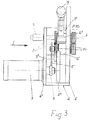
Fig. 3 eine Stirnansicht der Richtrolleneinheit nach dem Pfeil III inFig. 1 ; -
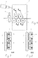
Fig. 4 eine schematische Seitenansicht der Richtrolleneinheit mit an das Richtgut angestellten Richtrollen; -
Fig. 5 eine gesprengte Teil-Detailansicht der Lagerung der Richtrollen und Antriebselemente in der Gehäusehauptplatte; -
Fig. 6 eine schematische Seitenansicht mit an das Richtgut angestellten Richtrollen; und
dieFig. 7 und 8 Details im Schnitt nach den Linien A-A und B-B inFig. 6 . - Die dargestellte Richtrolleneinheit ist zum Geradrichten von langgestrecktem Richtgut 1 bestimmt, wie Drähte, Stäbe, Profile, Bänder usw. Das Richtgut 1 kann eckigen oder runden Querschnitt haben und abgelängt bzw. in Stabform oder Wickelform vorliegen. Ein aus im wesentlichen drei miteinander verbundenen Platten 2', 2", 2"' bestehendes Gehäuse 2 (
Fig. 3 ) nimmt ein oder mehrere in Vorschubrichtung P hintereinander geschaltete Paare von oberen und unteren Richtrollen 6 auf, die zu beiden Seiten einer Richtgutvorschubebene angeordnet sind. Eine an der Außenseite der einen Gehäuseplatte 2" montierte, z.B. elektrische Antriebsvorrichtung 3 dient zum Antrieb einer nachfolgend erläuterten Getriebevorrichtung 4 zum Verteilen der von der Antriebsvorrichtung 3 aufgebrachten Vorschubkraft auf die einzelnen Richtrollen 6. - Ferner sind im Gehäuse 2 eine von Hand oder motorisch betätigte Einzelverstelleinrichtung 7 und eine von Hand oder motorisch betätigte Zentralverstelleinrichtung 8 für die Richtrollen 6 angeordnet. Die Motorbetätigung wird über eine nicht gezeigte Programmsteuereinrichtung angesteuert. Das Gehäuse 2 dient zugleich zum Schutz gegen Schmutz und der mechanischen Beschädigungen, z.B. durch das Richtgut 1.
- Die von der nicht gezeigten Programmsteuereinrichtung angesteuerte Antriebsvorrichtung 3 weist ein Antriebszahnritzel 5 für die Verteil-Getriebevorrichtung 4 auf, welche ausgehend von einem Verteilzahnrad 5' und einer in einer mittleren Gehäuseplatte 2'" gelagerten Zwischenzahnwelle 5" die Antriebsleistung des Antriebszahnrades 5 über eine Reihe von miteinander kämmenden Zahnrädern 4' auf die zugeordneten Richtrollen 6 verteilt. Beim gezeigten Beispiel sind alle Richtrollen 6 angetrieben. Bei einer nicht gezeigten Ausführungsform können die Zahnräder 4' einzeln angetrieben werden. Anstelle der Zahnräder 4' können z.B. auch Riemen vorgesehen sein.
- Die Geometrie dieser Verteil-Getriebevorrichtung 4 ist so gewählt, daß die abtriebsseitig angeordneten oberen Richtrollen 6 den Erfordernissen der Richtgeometrie und der Richtqualität sowie der Vorschubkraft entsprechend unabhängig voneinander oder gemeinsam an das Richtgut 1 angestellt werden können, ohne dabei den Vorschubkraftschluß zu verlieren bzw. zu unterbrechen.
- Die Richtrollen 6 sind als Doppelspur-Richtlinien ausgebildet, wobei die unteren Richtrollen 6 in einem in der Gehäuseplatte 2' drehbar gelagerten Lagergehäuse 6' gelagert sind, wogegen das obere Lagergehäuse 6" mit den darin gelagerten oberen Richtrollen 6 über die beiden Schwingen 14 mit dem unteren Lagergehäuse 6' fest verbunden ist, wie die
Fig. 2 und5 illustrieren. - Die oberhalb des Richtgutes 1 angeordneten Richtrollen 6 und Antriebszahnräder 4' sind über die Einzelverstelleinrichtung 8' und über die Lagergehäuse 6" mit den Verstelleinrichtungen 7, 8 verbunden. Der Drehmittelpunkt 4" der Einzelverstelleinrichtung 8' ist so positioniert, daß bei Zustellung der Richtrollen 6 an das Richtgut 1 die Zahnräder 4' immer im Eingriff sind.
- Diese Konstruktion ermöglicht es, das gesamte Verteilgetriebe 4 im Sinne der Pfeile P2, P3 (
Fig. 1 ) um Lagerpunkte zu verschwenken, die gemäßFig. 5 durch die Achsen 4" der in der Gehäusehauptplatte 2' gelagerten oberen Richtrollen 6 definiert sind. - Die zugleich als Vorschubelemente für das Richtgut 1 dienenden Richtrollen 6 können mit glatter, aber auch zur Erhöhung der Reibung mit profilierter Oberfläche ausgeführt werden. Insbesondere kann das Profil der Richtrollen 6 V-Form, wie beim gezeigten Ausführungsbeispiel, Kreisform, Ellipsenform oder eine beliebige andere Form haben.
- Die Verstellung bzw. Anstellung der Richtrollen 6 an das Richtgut 1 erfolgt quer zur Vorschubrichtung (Pfeil P4 in
Fig. 4 ), beim dargestellten Beispiel über die Zentralverstelleinrichtung 8 und die Einzelverstelleinrichtung 8'. Alternativ dazu ist auch eine lineare Zustellung möglich. - Die oberen Richtrollen 6 können auch einzeln von Hand oder motorisch im Sinne des Pfeiles P1 in
Fig. 1 über die Verstellspindel 7 an das Richtgut 1 angestellt werden. - Wenn alle Richtrollen 6 über das in der Gehäusehauptplatte 2' bei 9' gelagerte zentrale Stellglied 9 der Zentralverstelleinrichtung 8 motorisch gemeinsam im Sinne des Pfeiles P3 in
Fig. 1 angestellt werden, wird beispielsweise der Einfädelvorgang des Richtgutes 1 erleichtert. Das Stellglied 9 kann als Hydraulikzylinder oder Elektromotor usw. ausgebildet werden. Die Einstellwerte für die verschiedenen Richtgüter der Verstelleinrichtungen 7, 8, die über die nicht gezeigte Programmsteuereinrichtung angesteuert werden, können im Teil- oder Vollautomatikbetrieb in der Steuereinrichtung gespeichert werden, so daß sie bei oftmaligem Wechsel des Richtgutes 1 rasch wiederhergestellt werden können. - Das Stellglied 9 der Zentralverstelleinrichtung 8 kann auch je nach den Erfordernissen von Hand, z.B. mittels einer Handkurbel oder motorisch über Handtaster sowie mittels der übergeordneten Programmsteuereinrichtung betätigt werden.
- Ein weiteres am Gehäuse 2 abgestütztes hydraulisches Stellglied 10 (
Fig. 3 ) dient zum Verstellen der Richtrollen 6 quer zur Richtebene im Sinne des Pfeiles P10 inFig. 3 . Auch dieses Stellglied 10 kann statt hydraulisch betätigbar für manuellen oder elektromotorischen Betrieb ausgeführt werden, wobei auch seine Funktionsweise mittels der Programmsteuereinrichtung geregelt werden kann. Es dient zugleich zum Kompensieren eventuell auftretender Torsionsspannungen im Richtgut 1. Schließlich ist einlaufseitig auch eine Rückzugklemmeinrichtung 13 für das Richtgut 1 vorgesehen. - Die
Fig. 6 bis 8 illustrieren den Betrieb der Richteinheit zum Richten zweier parallel in Doppelspur-Richtrollen 6 geführten Drähten 11, 12. Dabei ist es zur Speisung einer nachgeordneten Drahtbiegemaschine häufig erforderlich, eine ungerade Anzahl von Drähten zu richten. Hiezu kann erfindungsgemäß abwechselnd der Antrieb eines Paares von Richtrollen 6 stillgesetzt werden. GemäßFig. 7 wird der Draht 11 gerichtet, wogegen der Draht 12 stillsteht und die zugeordneten Richtrollen 6 in Lagern 15 leer mitlaufen. InFig. 8 ist die Situation umgekehrt. - Die erfindungsgemäße Richteinheit ist imstande, das Richtgut 1 exakt in Position zu halten, unabhängig von der Anzahl der Richtspuren, und ermöglicht es ferner, die Vorschubrichtung umzukehren. Zum Einfädeln des Richtgutes 1 kann vor und/ oder hinter der Richteinheit eine nicht gezeigte Treibvorrichtung vorgesehen werden.
- Im Rahmen der Erfindung kann die Bahn des Richtgutes 1 eine beliebige Bahnkurve sein, welcher die zum Richten erforderlichen Zustellungen überlagert werden.
- Es versteht sich, daß die Erfindung im Rahmen des Erfindungsgedankens verschiedentlich abgewandelt werden kann, insbesondere, was die Ausbildung der Antriebe und die Richtrollengeometrie betrifft.
- Beispielsweise kann die Richtrolleneinheit beim Richten von Drähten einen gängigen Richtgutdurchmesserbereich von 3 - 20 mm abdecken. Bei Richtvorrichtungen liegt der Durchmesserbereich der Richtrollen 6 üblicherweise zwischen 50 und 150 mm.
- Die Erfindung ist derart modular aufgebaut, daß eingangsseitig, je nach den Erfordernissen, Elektro-, Hydraulik-, Pneumatikmotoren und Klinkenantriebe direkt oder über Getriebe mit fixer oder auch variabler Übersetzung, z.B. ein Schaltgetriebe, vorgesehen werden können.
Claims (12)
- Richtrolleneinheit für draht-, stab- oder bandförmiges Richtgut (1) aus Stahl, insbesondere Drähte, Stäbe, Profile, Bänder, mit paarweise zusammenwirkenden Richtrollen (6), die gegen das Richtgut anstellbar und von diesem lüftbar sind, wobei die Richtrollen (6) angetrieben sind und die für den Richtvorgang erforderliche Vorschubkraft durch Reibung der Richtrollen (6) in das Richtgut (1) eingebracht wird, und wobei die Richtrollen (6) mit zugeordneten Antriebselementen (4') gekuppelt sind, die von einer Antriebsvorrichtung (3) über ein Antriebskraft-Verteilgetriebe (4) antreibbar sind, dadurch gekennzeichnet, daß das Antriebskraft-Verteilgetriebe (4) den Richtrollen (6) zugeordnete Paare von oberen und unteren Zahnrädern (4') aufweist, deren Achsen ebenso wie die Achsen der Richtrollen (6) über Schwingen (14) gekuppelt sind, wobei die unteren Zahnräder (4') in einer Gehäusehauptplatte (2') über Doppellager (6') gelagert sind, wogegen die oberen Zahnräder (4') über die Schwingen (14) und ein drehbar gelagertes Lagergehäuse (6") in derselben Gehäusehauptplatte (2') gelagert und mit der Verstelleinrichtung (8) und (8') gekuppelt sind.
- Richtrolleneinheit nach Anspruch 1, dadurch gekennzeichnet, daß die Richtrollen (6) einzeln oder gemeinsam antreibbar sind.
- Richtrolleneinheit nach einem der Ansprüche 1 oder 2, dadurch gekennzeichnet, daß die Anstellung der Richtrollen (6) an das Richtgut (1) ohne Unterbrechung des Vorschubkraftschlusses ausführbar ist.
- Richtrolleneinheit nach einem der Ansprüche 1 bis 3, dadurch gekennzeichnet, daß die Richtrollen (6) einzeln von Hand oder motorgetrieben an das Richtgut (1) anstellbar und von diesem lüftbar sind.
- Richtrolleneinheit nach einem der Ansprüche 1 bis 3, dadurch gekennzeichnet, daß alle Richtrollen (6) von Hand oder über eine motorgetriebene Zentralverstelleinrichtung (8) gemeinsam an das Richtgut (1) anstellbar und von diesem lüftbar sind.
- Richtrolleneinheit nach einem der Ansprüche 1 bis 5, dadurch gekennzeichnet, daß die Richtrollen (6) glatt oder profiliert ausgeführt sind.
- Richtrolleneinheit nach Anspruch 6, dadurch gekennzeichnet, daß das Profil der Richtrollen (6) V-Form, Kreisform Ellipsenform oder eine beliebige andere Form hat.
- Richtrolleneinheit nach einem der Ansprüche 1 bis 7, dadurch gekennzeichnet, daß die Richtrollen (6) als Doppelspur-Richtrollen zum gleichzeitigen oder abwechselnden Richten zweier parallel geführter Richtgüter (1) ausgebildet sind.
- Richtrolleneinheit einem der Ansprüche 1 bis 8, dadurch gekennzeichnet, daß sowohl die Einzelverstelleinrichtung (8') als auch die Zentralverstelleinrichtung (8) durch ein motorgetriebenes Stellglied (9) beaufschlagbar sind.
- Richtrolleneinheit nach einem der Ansprüche 1 bis 9, dadurch gekennzeichnet, daß die Einzelverstelleinrichtung (8') eine Einstellspindel (7) aufweist, welche die Einzelverstelleinrichtung (8') mit der Zentralverstelleinrichtung (8) verbindet.
- Richtrolleneinheit nach einem der Ansprüche 1 bis 10, dadurch gekennzeichnet, daß zumindest eine der Richtrollen (6) durch ein Stellglied (10) quer zur Richtebene verstellbar ist.
- Richtrolleneinheit nach Anspruch 11, dadurch gekennzeichnet, daß das Stellglied (10) manuell, motorisch oder programmgesteuert betätigbar ist.
Applications Claiming Priority (2)
| Application Number | Priority Date | Filing Date | Title |
|---|---|---|---|
| ATA865/2012A AT512898B1 (de) | 2012-08-03 | 2012-08-03 | Richtrolleneinheit |
| PCT/AT2013/000023 WO2014019000A1 (de) | 2012-08-03 | 2013-02-11 | Richtrolleneinheit |
Publications (2)
| Publication Number | Publication Date |
|---|---|
| EP2879815A1 EP2879815A1 (de) | 2015-06-10 |
| EP2879815B1 true EP2879815B1 (de) | 2017-05-31 |
Family
ID=47832830
Family Applications (1)
| Application Number | Title | Priority Date | Filing Date |
|---|---|---|---|
| EP13707799.6A Active EP2879815B1 (de) | 2012-08-03 | 2013-02-11 | Richtrolleneinheit |
Country Status (7)
| Country | Link |
|---|---|
| US (1) | US20150209850A1 (de) |
| EP (1) | EP2879815B1 (de) |
| AT (1) | AT512898B1 (de) |
| ES (1) | ES2633603T3 (de) |
| TW (1) | TW201406482A (de) |
| WO (1) | WO2014019000A1 (de) |
| ZA (1) | ZA201500678B (de) |
Cited By (1)
| Publication number | Priority date | Publication date | Assignee | Title |
|---|---|---|---|---|
| KR102934325B1 (ko) | 2025-12-01 | 2026-03-09 | (주)에이텍 | 링크형 동력전달 구조를 갖는 상하부 이송롤러형 선재 공급장치 |
Families Citing this family (14)
| Publication number | Priority date | Publication date | Assignee | Title |
|---|---|---|---|---|
| AT515282B1 (de) * | 2014-03-31 | 2015-08-15 | Evg Entwicklung Verwert Ges | Dressurvorrichtung |
| CN107824638B (zh) * | 2017-11-20 | 2023-09-12 | 无锡华联科技集团有限公司 | 钢管束矫直机 |
| CN108906919B (zh) * | 2018-07-17 | 2024-03-22 | 宣化钢铁集团有限责任公司 | 一种带有滑板导向垂直压下的连续矫直机 |
| CN108598010B (zh) * | 2018-07-18 | 2024-02-20 | 连云港瑞而盛电子科技有限公司 | 引直机 |
| CN109175153A (zh) * | 2018-10-02 | 2019-01-11 | 河北骄阳丝网设备有限责任公司 | 金属丝应力消除调直机及调直金属丝的方法 |
| CN110893424A (zh) * | 2019-12-20 | 2020-03-20 | 浙江康士达科技股份有限公司 | 一种钢带压直装置 |
| CN112872081A (zh) * | 2020-12-30 | 2021-06-01 | 江苏轩辕特种材料科技有限公司 | 一种高强度镁合金板带连续挤压生产系统及其工作方法 |
| DE102021210458A1 (de) * | 2021-09-21 | 2023-03-23 | Sms Group Gmbh | Richtmaschine sowie Verfahren zum Richten |
| CN113909335B (zh) * | 2021-11-29 | 2022-07-19 | 深圳市华明博机电设备工程有限公司 | 一种应力消除高铁车组制造车身整平装置 |
| CN114733931B (zh) * | 2022-01-17 | 2023-09-15 | 肇庆新亚铝铝业有限公司 | 一种铝型材智能矫直机及铝型材矫直工艺 |
| CN114951500A (zh) * | 2022-06-10 | 2022-08-30 | 梁刚 | 一种电线生产用自动矫直机 |
| AT18332U1 (de) * | 2023-03-16 | 2024-10-15 | Evg Entwicklungs U Verwertungs Ges M B H | Vorrichtung zum automatischen Richten von längserstrecktem Richtgut und Verfahren hierzu |
| CN117920799B (zh) * | 2024-03-22 | 2024-06-04 | 潍坊恒睿达铝业有限公司 | 铝合金管矫直扩孔一体机 |
| EP4650075A1 (de) * | 2024-05-15 | 2025-11-19 | Big Jurij GmbH | Vorrichtung zum richten von metallprofilen |
Family Cites Families (9)
| Publication number | Priority date | Publication date | Assignee | Title |
|---|---|---|---|---|
| DE638042C (de) * | 1935-09-11 | 1936-11-09 | Wagner & Co Werkzeugmaschinenf | Vorrichtung zum Richten von Metallstaeben, insbesondere von solchen mit Winkelprofil |
| DE1812588A1 (de) * | 1968-12-04 | 1970-06-18 | Schmitz Soehne Gmbh J H | Rollenrichtmaschine mit angetriebenen Richtrollenpaaren |
| DE2824217A1 (de) * | 1978-06-02 | 1979-12-06 | Schloemann Siemag Ag | Richtmaschine fuer bleche und baender |
| US4571821A (en) * | 1983-08-26 | 1986-02-25 | Westinghouse Electric Corp. | Sleeve insertion |
| DE4200922A1 (de) * | 1992-01-16 | 1993-07-22 | Schloemann Siemag Ag | Verfahren und vorrichtung zum richten von blech |
| DE4415048A1 (de) * | 1994-04-29 | 1995-11-02 | Schloemann Siemag Ag | Richtmaschine zum Richten von Blechen und Bändern |
| DE4422878A1 (de) * | 1994-06-30 | 1996-01-11 | Schloemann Siemag Ag | Rollenrichtmaschine zum Richten von profiliertem Walzgut |
| IT1291259B1 (it) * | 1997-03-13 | 1998-12-30 | Schnell Spa | Gruppo raddrizzante bifilare per materiali metallici in filo e simili. |
| EP1038602B1 (de) * | 1999-03-26 | 2002-05-22 | SMS Demag AG | Verfahren und maschinelle Einrichtung zum Richten von Profilen |
-
2012
- 2012-08-03 AT ATA865/2012A patent/AT512898B1/de active
-
2013
- 2013-02-11 WO PCT/AT2013/000023 patent/WO2014019000A1/de not_active Ceased
- 2013-02-11 EP EP13707799.6A patent/EP2879815B1/de active Active
- 2013-02-11 ES ES13707799.6T patent/ES2633603T3/es active Active
- 2013-02-11 US US14/419,421 patent/US20150209850A1/en not_active Abandoned
- 2013-05-15 TW TW102117150A patent/TW201406482A/zh unknown
-
2015
- 2015-01-29 ZA ZA2015/00678A patent/ZA201500678B/en unknown
Non-Patent Citations (1)
| Title |
|---|
| None * |
Cited By (1)
| Publication number | Priority date | Publication date | Assignee | Title |
|---|---|---|---|---|
| KR102934325B1 (ko) | 2025-12-01 | 2026-03-09 | (주)에이텍 | 링크형 동력전달 구조를 갖는 상하부 이송롤러형 선재 공급장치 |
Also Published As
| Publication number | Publication date |
|---|---|
| AT512898B1 (de) | 2013-12-15 |
| WO2014019000A1 (de) | 2014-02-06 |
| TW201406482A (zh) | 2014-02-16 |
| AT512898A4 (de) | 2013-12-15 |
| US20150209850A1 (en) | 2015-07-30 |
| ZA201500678B (en) | 2016-01-27 |
| ES2633603T3 (es) | 2017-09-22 |
| EP2879815A1 (de) | 2015-06-10 |
Similar Documents
| Publication | Publication Date | Title |
|---|---|---|
| AT512898B1 (de) | Richtrolleneinheit | |
| DE102006014454B3 (de) | Stanzvorrichtung mit Zuführeinrichtung | |
| DE102010004781B4 (de) | Trenn- und Abisoliereinrichtung für eine Kabelverarbeitungsmaschine | |
| EP0473036B1 (de) | Drahtbiegemaschine für mit Isolierung versehenen Draht | |
| EP0927444A1 (de) | Endloskabelbearbeitungsvorrichtung | |
| DE3889286T2 (de) | Überwachungseinheit zum Positionieren der Messer in einer Längsschneidvorrichtung. | |
| DE10341992A1 (de) | Stapelbildungsvorrichtung | |
| EP0622136A1 (de) | Vorrichtung zur Herstellung von Bewehrungsgittern für Betonplatten | |
| DE2044641A1 (de) | Verfahren und Vorrichtung zum automati sehen Zertrennen eines kontinuierlich be wegten Glasbandes | |
| EP2896490B1 (de) | Kreismesserantrieb, insbesondere für brotschneidemaschinen | |
| EP3419776A1 (de) | Bearbeitungsanlage zum bearbeiten von rundmaterial umfassend eine zufördereinrichtung mit dauermagneten | |
| DE102010054111B4 (de) | Richtwerk zum rotierenden Richten von Draht | |
| EP2457443B1 (de) | Verfahren zum maschinellen Verdrillen von Teigstreifen | |
| EP3600712B1 (de) | Drahtrichtanlage und verfahren zum ausrichten von drähten mittels der drahtrichtanlage | |
| DE19937691B4 (de) | Strangabzug-Maschine | |
| EP2823704A2 (de) | Vorrichtung und Verfahren zum Entfernen von Pflanzenteilen | |
| EP1183117A1 (de) | Verfahren zum herstellen eines bandförmigen vormaterials aus metall, insbesondere eines solchen vormaterials welches in regelmässig wiederkehrenden abschnitten profiliert ist, und die verwendung einer vorrichtung dafür | |
| EP0924007A2 (de) | Verfahren zum Abscheiden von Drahtstücken vorgegebener Länge von einem Draht sowie Vorrichtung zur Durchführung dieses Verfahrens | |
| DE19853869A1 (de) | Vorrichtung zur Strangführung und damit ausgerüstete Rundflechtmaschine | |
| DE2226116C3 (de) | Fördervorrichtung von dünnen Stäben zum Schneiden zu maßhaltigen Werkstücken | |
| DD156864A3 (de) | Vorrichtung zum automatischen richten und ablaengen von rohren geringen durchmessers vom bund | |
| DE2734009A1 (de) | Walzbremseinrichtung | |
| DE3031058A1 (de) | Maschine zum kaltstrecken und richten | |
| DE2226116B2 (de) | Foerdervorrichtung von duennen staeben zum schneiden zu masshaltigen werkstuecken | |
| CH508518A (de) | Einrichtung zum Binden von Stückgütern, insbesondere Stangenbündeln und Verfahren zum Betrieb dieser Einrichtung |
Legal Events
| Date | Code | Title | Description |
|---|---|---|---|
| PUAI | Public reference made under article 153(3) epc to a published international application that has entered the european phase |
Free format text: ORIGINAL CODE: 0009012 |
|
| 17P | Request for examination filed |
Effective date: 20141230 |
|
| AK | Designated contracting states |
Kind code of ref document: A1 Designated state(s): AL AT BE BG CH CY CZ DE DK EE ES FI FR GB GR HR HU IE IS IT LI LT LU LV MC MK MT NL NO PL PT RO RS SE SI SK SM TR |
|
| AX | Request for extension of the european patent |
Extension state: BA ME |
|
| RIN1 | Information on inventor provided before grant (corrected) |
Inventor name: KAINZ, PETER Inventor name: TREMMEL, ROBERT Inventor name: RESCH, WALTER |
|
| DAX | Request for extension of the european patent (deleted) | ||
| GRAP | Despatch of communication of intention to grant a patent |
Free format text: ORIGINAL CODE: EPIDOSNIGR1 |
|
| INTG | Intention to grant announced |
Effective date: 20170131 |
|
| GRAS | Grant fee paid |
Free format text: ORIGINAL CODE: EPIDOSNIGR3 |
|
| GRAA | (expected) grant |
Free format text: ORIGINAL CODE: 0009210 |
|
| AK | Designated contracting states |
Kind code of ref document: B1 Designated state(s): AL AT BE BG CH CY CZ DE DK EE ES FI FR GB GR HR HU IE IS IT LI LT LU LV MC MK MT NL NO PL PT RO RS SE SI SK SM TR |
|
| REG | Reference to a national code |
Ref country code: CH Ref legal event code: EP Ref country code: GB Ref legal event code: FG4D Free format text: NOT ENGLISH |
|
| REG | Reference to a national code |
Ref country code: AT Ref legal event code: REF Ref document number: 896976 Country of ref document: AT Kind code of ref document: T Effective date: 20170615 |
|
| REG | Reference to a national code |
Ref country code: IE Ref legal event code: FG4D Free format text: LANGUAGE OF EP DOCUMENT: GERMAN |
|
| REG | Reference to a national code |
Ref country code: CH Ref legal event code: NV Representative=s name: ISLER AND PEDRAZZINI AG, CH |
|
| REG | Reference to a national code |
Ref country code: DE Ref legal event code: R096 Ref document number: 502013007368 Country of ref document: DE |
|
| REG | Reference to a national code |
Ref country code: NL Ref legal event code: FP |
|
| REG | Reference to a national code |
Ref country code: ES Ref legal event code: FG2A Ref document number: 2633603 Country of ref document: ES Kind code of ref document: T3 Effective date: 20170922 |
|
| REG | Reference to a national code |
Ref country code: LT Ref legal event code: MG4D |
|
| PG25 | Lapsed in a contracting state [announced via postgrant information from national office to epo] |
Ref country code: FI Free format text: LAPSE BECAUSE OF FAILURE TO SUBMIT A TRANSLATION OF THE DESCRIPTION OR TO PAY THE FEE WITHIN THE PRESCRIBED TIME-LIMIT Effective date: 20170531 Ref country code: HR Free format text: LAPSE BECAUSE OF FAILURE TO SUBMIT A TRANSLATION OF THE DESCRIPTION OR TO PAY THE FEE WITHIN THE PRESCRIBED TIME-LIMIT Effective date: 20170531 Ref country code: LT Free format text: LAPSE BECAUSE OF FAILURE TO SUBMIT A TRANSLATION OF THE DESCRIPTION OR TO PAY THE FEE WITHIN THE PRESCRIBED TIME-LIMIT Effective date: 20170531 Ref country code: NO Free format text: LAPSE BECAUSE OF FAILURE TO SUBMIT A TRANSLATION OF THE DESCRIPTION OR TO PAY THE FEE WITHIN THE PRESCRIBED TIME-LIMIT Effective date: 20170831 |
|
| PG25 | Lapsed in a contracting state [announced via postgrant information from national office to epo] |
Ref country code: BG Free format text: LAPSE BECAUSE OF FAILURE TO SUBMIT A TRANSLATION OF THE DESCRIPTION OR TO PAY THE FEE WITHIN THE PRESCRIBED TIME-LIMIT Effective date: 20170831 Ref country code: IS Free format text: LAPSE BECAUSE OF FAILURE TO SUBMIT A TRANSLATION OF THE DESCRIPTION OR TO PAY THE FEE WITHIN THE PRESCRIBED TIME-LIMIT Effective date: 20170930 Ref country code: RS Free format text: LAPSE BECAUSE OF FAILURE TO SUBMIT A TRANSLATION OF THE DESCRIPTION OR TO PAY THE FEE WITHIN THE PRESCRIBED TIME-LIMIT Effective date: 20170531 Ref country code: SE Free format text: LAPSE BECAUSE OF FAILURE TO SUBMIT A TRANSLATION OF THE DESCRIPTION OR TO PAY THE FEE WITHIN THE PRESCRIBED TIME-LIMIT Effective date: 20170531 Ref country code: LV Free format text: LAPSE BECAUSE OF FAILURE TO SUBMIT A TRANSLATION OF THE DESCRIPTION OR TO PAY THE FEE WITHIN THE PRESCRIBED TIME-LIMIT Effective date: 20170531 |
|
| REG | Reference to a national code |
Ref country code: FR Ref legal event code: PLFP Year of fee payment: 6 |
|
| PG25 | Lapsed in a contracting state [announced via postgrant information from national office to epo] |
Ref country code: SK Free format text: LAPSE BECAUSE OF FAILURE TO SUBMIT A TRANSLATION OF THE DESCRIPTION OR TO PAY THE FEE WITHIN THE PRESCRIBED TIME-LIMIT Effective date: 20170531 Ref country code: DK Free format text: LAPSE BECAUSE OF FAILURE TO SUBMIT A TRANSLATION OF THE DESCRIPTION OR TO PAY THE FEE WITHIN THE PRESCRIBED TIME-LIMIT Effective date: 20170531 Ref country code: RO Free format text: LAPSE BECAUSE OF FAILURE TO SUBMIT A TRANSLATION OF THE DESCRIPTION OR TO PAY THE FEE WITHIN THE PRESCRIBED TIME-LIMIT Effective date: 20170531 Ref country code: CZ Free format text: LAPSE BECAUSE OF FAILURE TO SUBMIT A TRANSLATION OF THE DESCRIPTION OR TO PAY THE FEE WITHIN THE PRESCRIBED TIME-LIMIT Effective date: 20170531 Ref country code: EE Free format text: LAPSE BECAUSE OF FAILURE TO SUBMIT A TRANSLATION OF THE DESCRIPTION OR TO PAY THE FEE WITHIN THE PRESCRIBED TIME-LIMIT Effective date: 20170531 |
|
| REG | Reference to a national code |
Ref country code: GR Ref legal event code: EP Ref document number: 20170402124 Country of ref document: GR Effective date: 20180119 |
|
| PG25 | Lapsed in a contracting state [announced via postgrant information from national office to epo] |
Ref country code: PL Free format text: LAPSE BECAUSE OF FAILURE TO SUBMIT A TRANSLATION OF THE DESCRIPTION OR TO PAY THE FEE WITHIN THE PRESCRIBED TIME-LIMIT Effective date: 20170531 Ref country code: SM Free format text: LAPSE BECAUSE OF FAILURE TO SUBMIT A TRANSLATION OF THE DESCRIPTION OR TO PAY THE FEE WITHIN THE PRESCRIBED TIME-LIMIT Effective date: 20170531 |
|
| REG | Reference to a national code |
Ref country code: DE Ref legal event code: R097 Ref document number: 502013007368 Country of ref document: DE |
|
| PLBE | No opposition filed within time limit |
Free format text: ORIGINAL CODE: 0009261 |
|
| STAA | Information on the status of an ep patent application or granted ep patent |
Free format text: STATUS: NO OPPOSITION FILED WITHIN TIME LIMIT |
|
| 26N | No opposition filed |
Effective date: 20180301 |
|
| PG25 | Lapsed in a contracting state [announced via postgrant information from national office to epo] |
Ref country code: SI Free format text: LAPSE BECAUSE OF FAILURE TO SUBMIT A TRANSLATION OF THE DESCRIPTION OR TO PAY THE FEE WITHIN THE PRESCRIBED TIME-LIMIT Effective date: 20170531 |
|
| PGFP | Annual fee paid to national office [announced via postgrant information from national office to epo] |
Ref country code: TR Payment date: 20180208 Year of fee payment: 6 |
|
| PG25 | Lapsed in a contracting state [announced via postgrant information from national office to epo] |
Ref country code: MT Free format text: LAPSE BECAUSE OF FAILURE TO SUBMIT A TRANSLATION OF THE DESCRIPTION OR TO PAY THE FEE WITHIN THE PRESCRIBED TIME-LIMIT Effective date: 20170531 Ref country code: MC Free format text: LAPSE BECAUSE OF FAILURE TO SUBMIT A TRANSLATION OF THE DESCRIPTION OR TO PAY THE FEE WITHIN THE PRESCRIBED TIME-LIMIT Effective date: 20170531 |
|
| REG | Reference to a national code |
Ref country code: IE Ref legal event code: MM4A |
|
| REG | Reference to a national code |
Ref country code: BE Ref legal event code: MM Effective date: 20180228 |
|
| PG25 | Lapsed in a contracting state [announced via postgrant information from national office to epo] |
Ref country code: LU Free format text: LAPSE BECAUSE OF NON-PAYMENT OF DUE FEES Effective date: 20180211 |
|
| PG25 | Lapsed in a contracting state [announced via postgrant information from national office to epo] |
Ref country code: IE Free format text: LAPSE BECAUSE OF NON-PAYMENT OF DUE FEES Effective date: 20180211 |
|
| PG25 | Lapsed in a contracting state [announced via postgrant information from national office to epo] |
Ref country code: BE Free format text: LAPSE BECAUSE OF NON-PAYMENT OF DUE FEES Effective date: 20180228 |
|
| REG | Reference to a national code |
Ref country code: AT Ref legal event code: MM01 Ref document number: 896976 Country of ref document: AT Kind code of ref document: T Effective date: 20180211 |
|
| PG25 | Lapsed in a contracting state [announced via postgrant information from national office to epo] |
Ref country code: AT Free format text: LAPSE BECAUSE OF NON-PAYMENT OF DUE FEES Effective date: 20180211 |
|
| PGFP | Annual fee paid to national office [announced via postgrant information from national office to epo] |
Ref country code: ES Payment date: 20200302 Year of fee payment: 8 Ref country code: NL Payment date: 20200121 Year of fee payment: 8 |
|
| PG25 | Lapsed in a contracting state [announced via postgrant information from national office to epo] |
Ref country code: PT Free format text: LAPSE BECAUSE OF FAILURE TO SUBMIT A TRANSLATION OF THE DESCRIPTION OR TO PAY THE FEE WITHIN THE PRESCRIBED TIME-LIMIT Effective date: 20170531 |
|
| PG25 | Lapsed in a contracting state [announced via postgrant information from national office to epo] |
Ref country code: HU Free format text: LAPSE BECAUSE OF FAILURE TO SUBMIT A TRANSLATION OF THE DESCRIPTION OR TO PAY THE FEE WITHIN THE PRESCRIBED TIME-LIMIT; INVALID AB INITIO Effective date: 20130211 Ref country code: CY Free format text: LAPSE BECAUSE OF FAILURE TO SUBMIT A TRANSLATION OF THE DESCRIPTION OR TO PAY THE FEE WITHIN THE PRESCRIBED TIME-LIMIT Effective date: 20170531 Ref country code: MK Free format text: LAPSE BECAUSE OF NON-PAYMENT OF DUE FEES Effective date: 20170531 |
|
| PG25 | Lapsed in a contracting state [announced via postgrant information from national office to epo] |
Ref country code: AL Free format text: LAPSE BECAUSE OF FAILURE TO SUBMIT A TRANSLATION OF THE DESCRIPTION OR TO PAY THE FEE WITHIN THE PRESCRIBED TIME-LIMIT Effective date: 20170531 |
|
| REG | Reference to a national code |
Ref country code: NL Ref legal event code: MM Effective date: 20210301 |
|
| PG25 | Lapsed in a contracting state [announced via postgrant information from national office to epo] |
Ref country code: NL Free format text: LAPSE BECAUSE OF NON-PAYMENT OF DUE FEES Effective date: 20210301 |
|
| REG | Reference to a national code |
Ref country code: ES Ref legal event code: FD2A Effective date: 20220513 |
|
| PG25 | Lapsed in a contracting state [announced via postgrant information from national office to epo] |
Ref country code: TR Free format text: LAPSE BECAUSE OF NON-PAYMENT OF DUE FEES Effective date: 20190211 |
|
| PG25 | Lapsed in a contracting state [announced via postgrant information from national office to epo] |
Ref country code: ES Free format text: LAPSE BECAUSE OF NON-PAYMENT OF DUE FEES Effective date: 20210212 |
|
| REG | Reference to a national code |
Ref country code: CH Ref legal event code: U11 Free format text: ST27 STATUS EVENT CODE: U-0-0-U10-U11 (AS PROVIDED BY THE NATIONAL OFFICE) Effective date: 20260311 |
|
| PGFP | Annual fee paid to national office [announced via postgrant information from national office to epo] |
Ref country code: GB Payment date: 20260128 Year of fee payment: 14 |
|
| PGFP | Annual fee paid to national office [announced via postgrant information from national office to epo] |
Ref country code: DE Payment date: 20260209 Year of fee payment: 14 |
|
| PGFP | Annual fee paid to national office [announced via postgrant information from national office to epo] |
Ref country code: IT Payment date: 20260220 Year of fee payment: 14 |
|
| PGFP | Annual fee paid to national office [announced via postgrant information from national office to epo] |
Ref country code: FR Payment date: 20260218 Year of fee payment: 14 |
|
| PGFP | Annual fee paid to national office [announced via postgrant information from national office to epo] |
Ref country code: CH Payment date: 20260311 Year of fee payment: 14 |
|
| PGFP | Annual fee paid to national office [announced via postgrant information from national office to epo] |
Ref country code: GR Payment date: 20260205 Year of fee payment: 14 |