EP2876752B1 - Spark plug - Google Patents
Spark plug Download PDFInfo
- Publication number
- EP2876752B1 EP2876752B1 EP13820671.9A EP13820671A EP2876752B1 EP 2876752 B1 EP2876752 B1 EP 2876752B1 EP 13820671 A EP13820671 A EP 13820671A EP 2876752 B1 EP2876752 B1 EP 2876752B1
- Authority
- EP
- European Patent Office
- Prior art keywords
- metal shell
- insulator
- thread
- spark plug
- inner face
- Prior art date
- Legal status (The legal status is an assumption and is not a legal conclusion. Google has not performed a legal analysis and makes no representation as to the accuracy of the status listed.)
- Active
Links
Images

Classifications
-
- H—ELECTRICITY
- H01—ELECTRIC ELEMENTS
- H01T—SPARK GAPS; OVERVOLTAGE ARRESTERS USING SPARK GAPS; SPARKING PLUGS; CORONA DEVICES; GENERATING IONS TO BE INTRODUCED INTO NON-ENCLOSED GASES
- H01T13/00—Sparking plugs
- H01T13/20—Sparking plugs characterised by features of the electrodes or insulation
- H01T13/36—Sparking plugs characterised by features of the electrodes or insulation characterised by the joint between insulation and body, e.g. using cement
-
- H—ELECTRICITY
- H01—ELECTRIC ELEMENTS
- H01B—CABLES; CONDUCTORS; INSULATORS; SELECTION OF MATERIALS FOR THEIR CONDUCTIVE, INSULATING OR DIELECTRIC PROPERTIES
- H01B3/00—Insulators or insulating bodies characterised by the insulating materials; Selection of materials for their insulating or dielectric properties
- H01B3/02—Insulators or insulating bodies characterised by the insulating materials; Selection of materials for their insulating or dielectric properties mainly consisting of inorganic substances
- H01B3/12—Insulators or insulating bodies characterised by the insulating materials; Selection of materials for their insulating or dielectric properties mainly consisting of inorganic substances ceramics
Definitions
- the present invention relates to a spark plug used for ignition in an internal combustion engine and the like.
- Size reduction of a spark plug is desired for purposes such as increasing the degree of freedom in designing an internal combustion engine.
- a spark plug with a nominal diameter of the thread of the metal shell of not more than 10 mm has been developed.
- An object of the present invention is to provide a technique to create a balance between airtight property and dielectric strength property of the spark plug can be achieved.
- a spark plug includes: a tubular insulator having an axial hole extending in a direction of an axis thereof (hereinafter, also referred to as an "axial direction"), the tubular insulator having an outer periphery with a tapered outer face where an outer diameter thereof decreases from a rear end to a front end thereof; a tubular metal shell having a through-hole extending in the axial direction through which the insulator is inserted, the tubular metal shell having a thread portion including an installation thread ridge on an outer periphery of the thread portion and a tapered inner face where an inner diameter thereof decreases from the rear end to the front end on an inner periphery of the thread portion; and a circular packing.
- the circular packing is sandwiched between the tapered outer face of the insulator and the tapered inner face of the metal shell for sealing the gap.
- the thread portion has a nominal diameter of not more than 10 mm; and at least one cross section including the axis satisfies expressions of: (A/B) ⁇ 3.1, B ⁇ 0.25, and (A + B) ⁇ 2.0.
- A represents a length (mm) of (a difference between an effective diameter of the thread portion and an inner diameter at a rear end of the tapered inner face)/2
- B represents a length (mm) of (a difference between the inner diameter at the rear end of the tapered inner face and an inner diameter at a front end of the tapered inner face)/2.
- the gap between the tapered outer face of the insulator and the tapered inner face of the metal shell cannot be properly sealed, resulting in a decrease in airtightness.
- B ⁇ 0.25 mm is satisfied, so that the area of the tapered inner face of the metal shell can be ensured, and the insulator can be properly supported.
- both airtight and dielectric strength properties of the spark plug can be achieved.
- the airtight and dielectric strength properties of the spark plug including the thread portion with the nominal diameter of not more than 10 mm can be achieved.
- the acute angle (which may be referred to as the first acute angle) formed by the tapered inner face of the metal shell and the plane perpendicular to the axis
- the sealing load in the axial direction tends to become large, whereby a part of the metal shell around the radially inner side of the tapered inner face tends to be deformed.
- the first acute angle is not more than the acute angle (which may be referred to as the second acute angle) formed by the tapered outer face of the insulator and the plane perpendicular to the axis
- a large load tends to be applied onto the radially inner part of the tapered inner face of the metal shell, so that similarly the metal shell tends to be deformed in the radially inner part of the tapered inner face.
- the radially inner part of the tapered inner face of the metal shell is deformed, the part and the insulator may contact each other, possibly resulting in the problem of insulator breakage.
- the first acute angle is excessively large, the sealing load tends to be increased toward the radially outer side, and deformation of the thread portion may be caused.
- the first acute angle is not less than 35 degrees and not more than 50 degrees and greater than the second acute angle.
- the difference between the hardness E and the hardness F (E - F) satisfies 15 Hv ⁇ (E - F) ⁇ 46 Hv, whereby insulator breakage or deformation of the thread portion can be suppressed.
- the present invention can be realized in various modes, such as in the form of a spark plug, or an internal combustion engine fitted with the spark plug.
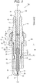
- FIG. 1 is a cross sectional view of a spark plug 100 according to the embodiment.
- the dash-dot line indicates an axis CO (which may also be referred to as an axis CO) of the spark plug 100.
- a direction parallel with the axis CO (upper-lower direction in FIG. 1 ) may also be referred to as the axial direction.
- a radial direction of a circle about the axis CO may be simply referred to as the radial direction, and a circumferential direction of the circle about the axis CO may simply be referred to as the circumferential direction.
- FIG. 1 is a cross sectional view of a spark plug 100 according to the embodiment.
- the dash-dot line indicates an axis CO (which may also be referred to as an axis CO) of the spark plug 100.
- a direction parallel with the axis CO (upper-lower direction in FIG. 1 ) may also be referred to as the axial direction.
- a lower direction may be referred to as a front end direction D1, while an upper direction may be referred to as a rear end direction D2.
- the lower side of FIG. 1 will be referred to as the front end of the spark plug 100, and the upper side of FIG. 1 will be referred to as the rear end of the spark plug 100.
- the spark plug 100 includes a ceramic insulator 10 as an insulator, a center electrode 20, a ground electrode 30, a terminal metal fitting 40, and a metal shell 50.
- the ceramic insulator 10 is formed by sintering alumina and the like.
- the ceramic insulator 10 is a substantially cylindrical member (tubular member) extending along the axial direction and including a through-hole 12 (axial hole) penetrating the ceramic insulator 10.
- the ceramic insulator 10 includes a flange portion 19, a rear end body portion 18, a front end body portion 17, a step portion 15, and an insulator nose portion 13.
- the rear end body portion 18 is located backward from the flange portion 19, and has an outer diameter smaller than an outer diameter of the flange portion 19.
- the front end body portion 17 is located forward of the flange portion 19, and has an outer diameter smaller than the outer diameter of the rear end body portion 18.
- the insulator nose portion 13 is located forward of the front end body portion 17, and has an outer diameter smaller than the outer diameter of the front end body portion 17.
- the insulator nose portion 13 has an increasingly smaller diameter toward the front end, and is exposed in the combustion chamber of an internal combustion engine (not shown) when the spark plug 100 is installed thereon.
- the step portion 15 is formed between the insulator nose portion 13 and the front end body portion 17.
- the step portion 15 includes a tapered outer face (15a in FIG. 2 ) on an outer periphery thereof, with an increasingly smaller outer diameter from the rear end to the front end (as will be described in detail below).
- the metal shell 50 is a substantially cylindrical member (tubular member) formed of an electrically conductive metal material (such as low carbon steel material) for fixing the spark plug 100 on the engine head (not shown) of the internal combustion engine.
- the metal shell 50 has a through-hole 59 penetrating the metal shell 50 along the axis CO.
- the metal shell 50 is disposed on the outer periphery of the ceramic insulator 10. Namely, the insulator 10 is inserted and held within the through-hole 59 of the metal shell 50.
- the front end of the ceramic insulator 10 is exposed on the front end of the metal shell 50.
- the rear end of the ceramic insulator 10 is exposed on the rear end of the metal shell 50.
- the metal shell 50 includes a hexagonal-columnar tool engaging portion 51 for engaging a spark plug wrench, an installation thread portion 52 for installing on the internal combustion engine, and a flange-shaped seating portion 54 formed between the tool engaging portion 51 and the installation thread portion 52.
- the installation thread portion 52 has a nominal diameter of not more than M10 (10 mm (millimeters)).
- the nominal diameter of the installation thread portion 52 is preferably M10 or M8, and is more preferably M10.
- a circular gasket 5 formed of a bent metal sheet is fitted between the installation thread portion 52 and the seating portion 54 of the metal shell 50.
- the gasket 5 seals a gap between the spark plug 100 and the internal combustion engine (engine head) when the spark plug 100 is installed on the internal combustion engine.
- the metal shell 50 further includes a thin-walled crimping portion 53 disposed on the rear end of the tool engaging portion 51, and a thin-walled compressive deformation portion 58 disposed between the seating portion 54 and the tool engaging portion 51.
- a ringed area formed between the inner periphery of a portion of the metal shell 50 extending from the tool engaging portion 51 to the crimping portion 53 and the outer periphery of the rear end body portion 18 of the ceramic insulator 10 are disposed. Between the two ring members 6 and 7 in this area, talc powder 9 is filled.
- the installation thread portion 52 of the metal shell 50 includes a shelf portion 523 protruding inwardly of the installation thread portion 52.
- the shelf portion 523 includes a tapered inner face (523a in FIG. 2 ) on the inner periphery thereof, with an increasingly smaller outer diameter from the rear end to the front end (as will be described in detail below).
- the rear end of the crimping portion 53 is bent radially inwardly and fixed onto the outer periphery of the ceramic insulator 10.
- the compressive deformation portion 58 of the metal shell 50 is compressively deformed as the crimping portion 53 fixed onto the outer periphery of the ceramic insulator 10 is pressed toward the front end.
- the weight with which the crimping portion 53 is pressed toward the front end during manufacturing is referred to as a crimping load.
- the step portion 15 of the ceramic insulator 10 is pressed onto the shelf portion 523 of the metal shell 50 via the circular plate packing 8. Namely, as will be described in detail below, a gap between the tapered outer face of the step portion 15 and the tapered inner face the shelf portion 523 is sealed via the plate packing 8. As a result, the gas in the combustion chamber of the internal combustion engine is prevented from leaking outside via the gap between the metal shell 50 and the ceramic insulator 10 by the plate packing 8.
- a length H1 of not less than 14.3 mm is ensured between the front end face (which may be referred to as a seating face) of the seating portion 54 and the rear end of the shelf portion 523.
- the plate packing 8 is formed of a high thermal conductivity material, such as copper or aluminum.
- the heat of the ceramic insulator 10 can be efficiently transmitted to the shelf portion 523 of the metal shell 50, so that the heat conduction of the spark plug 100 is improved and thermal resistance can be increased.
- the center electrode 20 is a bar-like member extending along the axis CO and inserted in the through-hole 12 of the insulator 10.
- the center electrode 20 has a structure including an electrode base material 21 and a core material 22 embedded inside the electrode base material 21.
- the electrode base material 21 is formed of nickel or an alloy with nickel as a principal component (such as INCONEL (registered trademark) 600).
- the core material 22 is formed of a material with better thermal conductivity than the alloy of the electrode base material 21, such as copper or an alloy with copper as a principal component.
- the front end of the center electrode 20 is exposed on the front end of the ceramic insulator 10.
- the center electrode 20 also includes a flange portion 24 (which may be referred to as an electrode flange portion or a flanged portion) disposed at a predetermined position in the axial direction, a head portion 23 (electrode head portion) disposed on the rear end with respect to the flange portion 24, and a nose portion 25 (electrode nose portion) disposed on the front end with respect to the flange portion 24.
- the flange portion 24 is supported by a step portion 16 of the ceramic insulator 10.
- an electrode tip 29 is joined by laser welding, for example. The configuration of the front end portion of the nose portion 25 of the center electrode 20 will be described below with reference to FIGS. 2 and 3 .
- the electrode tip 29 is formed of a material with a high melting point noble metal as a principal component.
- the material of the electrode tip 29 may include iridium (Ir) or an alloy with Ir as a principal component. Specifically, Ir-5Pt alloy (an iridium alloy containing 5% by mass of platinum) and the like is often used.
- the ground electrode 30 is joined to the front end of the metal shell 50.
- the electrode base material of the ground electrode 30 is formed of a highly corrosion resistant metal, such as the INCONEL 600 nickel alloy.
- the ground electrode 30 includes a base material proximal end portion 32 that is joined to the front end face of the metal shell 50 by welding, for example. As a result, the ground electrode 30 is electrically connected to the metal shell 50.
- the base material front end portion 31 of the ground electrode 30 is bent such that one side face of the base material front end portion 31 is disposed axially opposite the electrode tip 29 of the center electrode 20 on the axis CO. On the one side face of the base material front end portion 31, an electrode tip 33 is welded at a position opposite the electrode tip 29 of the center electrode 20.
- Pt platinum
- Pt-20Ir alloy a platinum alloy containing 20% by mass of iridium
- the terminal metal fitting 40 is a bar-like member extending along the axis CO.
- the terminal metal fitting 40 is formed of an electrically conductive metal material (such as low carbon steel), with a metal layer (such as a Ni layer) formed on the surface thereof by plating, for example, for corrosion prevention.
- the terminal metal fitting 40 includes a flange portion 42 (terminal chin portion) disposed at a predetermined position in the axial direction, a cap installing portion 41 located backward from the flange portion 42, and a nose portion 43 (terminal nose portion) disposed on the front end with respect to the flange portion 42.
- the cap installing portion 41 including the rear end of the terminal metal fitting 40 is exposed on the rear end of the ceramic insulator 10.
- the nose portion 43 including the front end of the terminal metal fitting 40 is inserted (press-fitted) into the through-hole 12 of the ceramic insulator 10.
- the cap installing portion 41 is configured to be fitted with a plug cap connected to a high-voltage cable (not shown) to apply a high voltage for producing a spark.
- a resistor element 70 for reducing radio interference noise at the time of spark generation is disposed in an area between the front end of the terminal metal fitting 40 and the rear end of the center electrode 20 in an area between the front end of the terminal metal fitting 40 and the rear end of the center electrode 20, a resistor element 70 for reducing radio interference noise at the time of spark generation is disposed.
- the resistor is formed of a composition including, for example, glass particles as a principal component, ceramic particles other than glass, and an electrically conductive material.
- a gap between the resistor element 70 and the center electrode 20 in the through-hole 12 is filled with an electrically conductive seal 60.
- a gap between the resistor element 70 and the terminal metal fitting 40 is filled with an electrically conductive seal 80 of glass and metal.
- FIG. 2 is an enlarged cross sectional view of a portion including the shelf portion 523 of the installation thread portion 52 of the metal shell 50 and the step portion 15 of the ceramic insulator 10. This view is that of a cross section of the spark plug 100 taken along a plane including the axis CO. On the outer periphery of the installation thread portion 52, mounting thread ridges 521 are formed.
- a dashed line BL in FIG. 2 indicates a virtual outer periphery (which may also be referred to as an effective diameter defining plane BL) defining an effective diameter R1 of the installation thread portion 52.
- the effective diameter defining plane BL is a virtual outer periphery such that a root depth DPa from the root of the thread ridges 521 to the effective diameter defining plane BL is equal to a crest height DPb from the crest of the thread ridges 521 to the effective diameter defining plane BL.
- the effective diameter R1 is approximately 9.3 mm.
- the shelf portion 523 of the installation thread portion 52 includes the tapered inner face 523a described above, an inner side face 523b, and an inversely tapered inner face 523c.
- the tapered inner face 523a is an inner periphery of a rear end portion of the shelf portion 523 where the inner diameter thereof gradually decreases from the rear end to the front end thereof.
- the inversely tapered inner face 523c is an inner periphery of a front end portion of the shelf portion 523 where the inner diameter thereof gradually increases from the rear end to the front end thereof.
- the inner side face 523b is an inner periphery extending from the front end of the tapered inner face 523a to the rear end of the inversely tapered inner face 523c, and is parallel with the axial direction.
- the terms "inner diameter” and “outer diameter” as used herein each refer to a straight line segment passing through the center.
- the tapered inner face 523a has an inner diameter R2 at a rear end P1.
- the inner diameter R2 may be the inner diameter of the installation thread portion 52 at a portion backward from the rear end P1 of the shelf portion 523.
- the tapered inner face 523a has an inner diameter R3 at a front end P2.
- the inner diameter R3 may be the inner diameter of the inner side face 523b.
- the length A may also be referred to as a thread portion thickness A.
- the length B may also be referred to as a shelf thickness B.
- an acute angle formed by the tapered inner face 523a of the shelf portion 523 and a virtual plane TF perpendicular to the axis CO is referred to as a first acute angle ⁇ 1.
- An inner diameter R6 at an inner periphery 13a of the through-hole 12 in the front end body portion 17 and the insulator nose portion 13 is determined in accordance with the outer diameter of the nose portion 25 (not shown in FIG. 2 ) of the center electrode 20 inserted into the through-hole 12.
- the inner diameter R6 is in a range of 1.5 mm to 1.8 mm, for example.
- a length D in the radial direction of a part of the insulator nose portion 13 opposite the shelf portion 523 of the metal shell 50 (the thickness of the part of the ceramic insulator 10) can be expressed as one half of the difference between the outer diameter R5 and the inner diameter R6. Namely, the length D ( FIG.
- the lengths C and D may also be referred to as insulation thicknesses C and D, respectively. The greater the insulation thicknesses C and D, the more the dielectric strength properties of the spark plug 100 is improved.
- the step portion 15 of the ceramic insulator 10 includes the tapered outer face 15a on the outer periphery thereof, with an increasingly smaller outer diameter from the rear end to the front end.
- a second acute angle ⁇ 2 an acute angle formed by the tapered outer face 15a of the step portion 15 and the virtual plane TF perpendicular to the axis CO ( FIG. 1 ) is referred to as a second acute angle ⁇ 2.
- the central portion between the curves at the front and rear ends is linear.
- the second acute angle ⁇ 2 is determined based on the linear part of the central portion.
- a width PW in a direction along the tapered inner face 523a is approximately 100% of the linear length of the tapered inner face 523a in the cross section of FIG. 2 , for example, and may preferably be in a range of 0.38 mm to 0.86 mm.
- A-3 First evaluation test:
- a crimping test and a dielectric strength test were conducted.
- the metal shell 50 was crimped by using 34 kN (kilo newton) of crimping load, and the presence or absence of the problem of the step portion 15 of the ceramic insulator 10 slipping from the shelf portion 523 of the metal shell 50 toward the front end (which may be hereafter referred to as slipping), and the presence or absence of the problem of the thread ridges 521 of the installation thread portion 52 of the metal shell 50 being deformed (which may hereafter be referred to as thread elongation) were tested.
- the presence or absence of slipping can be visually confirmed, while the presence or absence of thread elongation can be confirmed by using a thread gauge.
- the sample was evaluated as "Good”.
- the sample was evaluated as "Poor”.
- the samples in which the ground electrode 30 was not bent toward the front end of the center electrode 20 were used so that no discharge was produced between the electrode tip 33 of the ground electrode 30 and the electrode tip 29 of the center electrode 20. Further, in these samples, a space GV between the metal shell 50 and the ceramic insulator 10 on the front end with respect to the plate packing 8 was filled with an insulating fluid so that no discharge was produced between the center electrode 20 and the ground electrode 30. A voltage was applied between the terminal metal fitting 40 and the metal shell 50 of the samples, and the applied voltage was increased until insulator penetration (dielectric breakdown) was caused.
- a B A/B A+B Crimping test Dielectric strength test 1-1 1.30 0.20 6.5 1.50 Poor (Slipping) Good 1-2 1.23 0.25 4.9 1.48 Good Good 1-3 1.38 0.40 3.5 1.78 Good Good 1-4 1.53 0.25 6.1 1.78 Good Good 1-5 1.38 0.45 3.1 1.83 Good Good 1-6 1.13 0.50 2.3 1.63 Poor (Thread extension) Good 1-7 1.28 0.30 4.3 1.58 Good Good 1-8 1.28 0.45 2.9 1.73 Poor (Thread extension) Good 1-9 1.54 0.45 3.4 1.99 Good Good 1-10 1.60 0.40 4.0 2.00 Good Good 1-11 1.70 0.40 4.1 2.10 Good Poor
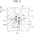
- FIG. 3 is a diagram explaining the stress loaded onto a portion including the shelf portion 523 of the installation thread portion 52 and the step portion 15 of the ceramic insulator 10.
- the shelf portion 523 is subjected to stress toward the front end, as indicated by white arrows AR1 and AR2 in FIG. 3 .
- the greater the shelf thickness B the greater the bending moment that would bend the installation thread portion 52 in the radial direction based on the stress.
- the greater the thread portion thickness A the greater the strength of the installation thread portion 52 with respect to the bending moment.
- the ratio (A/B) is preferably not less than 3.1.
- the nominal diameter of the installation thread portion 52 is a fixed value (such as 10 mm)
- the greater A or (A + B) the smaller the inner diameter R3 of the shelf portion 523 of the metal shell 50 becomes.
- the insulation thicknesses C and D ( FIG. 2 ) of the ceramic insulator 10 are decreased.
- the insulation thicknesses C and D of the ceramic insulator 10 cannot be ensured, and the dielectric strength properties may be decreased.
- (A + B) is greater than 2.0 mm, therefore, A or (A + B) is excessively large and therefore the insulation thickness C or D is excessively small, resulting in a decrease in dielectric strength properties.
- (A + B) is preferably less than 2.0 mm.
- the shelf thickness B may become large even when the ratio (A/B) is not less than 3.1, resulting in an increase in the area of the tapered inner face 523a.
- the area of the tapered inner face 523a may become so large that, in order to ensure the required sealing pressure (the load per unit area) between the tapered inner face 523a and the plate packing 8, the crimping load may need to be increased. From this viewpoint too, a relatively small (A + B) is preferable.
- the thread portion thickness A and the shelf thickness B preferably satisfy (A/B) ⁇ 3.1, B ⁇ 0.25, and (A + B) ⁇ 2.0. In this way, both dielectric strength property and airtightness can be achieved in the spark plug 100.
- the differences between the samples in the test results of the evaluation test are presumably due mainly to the differences in the thread portion thickness A and the shelf thickness B.
- the above preferable ranges of the thread portion thickness A and the shelf thickness B are presumed to be applicable regardless of the configuration other than the thread portion thickness A and the shelf thickness B.
- a second evaluation test six kinds of samples satisfying the preferable ranges clarified by the first evaluation test were prepared, and the crimping test and the dielectric strength test were conducted under even more strict conditions than in the first evaluation test. Namely, in the second evaluation test, six kinds of samples of the spark plug 100 with the nominal diameter of the installation thread portion 52 of 10 mm were used. In these six kinds of samples, the metal shell 50 had various thread portion thicknesses A and shelf thicknesses B.
- the metal shell 50 of each sample was crimped by using 36 kN of crimping load.
- the evaluation method was the same as for the crimping test according to the first evaluation test.
- the dielectric strength test evaluation was "Good”
- the dielectric strength test evaluation was "Poor”. This is presumably due to the fact that, when the thread portion thickness A exceeds 1.54 mm, the insulation thicknesses C and D ( FIG. 2 ) cannot be ensured, resulting in a decrease in dielectric strength property.
- the thread portion thickness A is not more than 1.54 mm.
- the shelf thickness B may have any value between 0.30 or more and 0.45 mm or less.
- the shelf thickness B may preferably be in a range of at least 0.25 ⁇ B ⁇ 0.45.
- the thread portion thickness A and the shelf thickness B satisfy 1.23 mm ⁇ A ⁇ 1.54 mm and 0.25 ⁇ B ⁇ 0.45, respectively.
- both dielectric strength property and airtightness can be satisfied at higher level. Namely, by further making the length A and the length B appropriate, the airtight and dielectric strength properties of the spark plug can be even more improved without causing insulator penetration or thread portion deformation.
- the outer diameter R4 of the front end body portion 17 of the ceramic insulator 10 ( FIG. 2 ) is 6.25 mm
- the inner diameter R3 at the front end P2 of the tapered inner face 523a (inner diameter of the inner side face 523b of the shelf portion 523) ( FIG. 2 ) is 5.6 mm.
- the first acute angle ⁇ 1 was set to be greater than the second acute angle ⁇ 2 ( ⁇ 1 > ⁇ 2). It is obvious, without even performing a test, that ⁇ 1 > ⁇ 2 is more preferable than ⁇ 1 ⁇ ⁇ 2, as described below.
- the interval between the tapered inner face 523a of the shelf portion 523 and the tapered outer face 15a of the ceramic insulator 10 becomes narrower toward the radially inner side.
- the compressive force at the radially inner side portion of the plate packing 8 becomes greater than the compressive force at the radially outer side portion of the plate packing 8 (see arrows AR3 and AR5 in FIG. 3 ).
- the plate packing 8 may be deformed and protrude into the radially inner side (see a dashed line TP in FIG. 3 ), possibly damaging the ceramic insulator 10.
- the stress applied to the tapered inner face 523a (see arrows AR1 and AR2 in FIG. 3 ). Namely, the stress applied to the radially inner side portion of the tapered inner face 523a (arrow AR2 in FIG. 3 ) becomes greater than the stress applied to the radially outer side portion of the tapered inner face 523a (arrow AR1 in FIG. 3 ). As a result, the shelf portion 523 is deformed in such a manner as to protrude into the radially inner side (see a dashed line BP in FIG. 3 ), possibly damaging the ceramic insulator 10.
- the first acute angle ⁇ 1 is preferably set to be greater than the second acute angle ⁇ 2 ( ⁇ 1 > ⁇ 2).
- the stress applied to the shelf portion 523 based on the crimping load can be resolved into a component parallel to the axial direction (arrows AR1 and AR2 in FIG. 3 ), and a component perpendicular to the axis (arrow AR7 in FIG. 3 ).
- the shelf portion 523 may be deformed in such a manner as to protrude toward the radially inner side (see the dashed line BP in FIG. 3 ), damaging the ceramic insulator 10.
- the breakage was caused in the insulator 10.
- the first acute angle ⁇ 1 exceeds 50 degrees, the component perpendicular to the axis (arrow AR7 in FIG. 3 ) becomes too large. As a result, the force that would bend the installation thread portion 52 is increased, causing deformation of the installation thread portion 52. Thus, the first acute angle ⁇ 1 of over 50 degrees could probably lead to deform the installation thread portion 52, thereby causing thread elongation.
- the first acute angle ⁇ 1 is preferably greater than the second acute angle ⁇ 2 and in a range of not less than 35 degrees and not more than 50 degrees.
- airtight and dielectric strength properties can be achieved at higher level. Namely, by making the first acute angle ⁇ 1 more appropriate, the airtight and dielectric strength properties of the spark plug can be even more improved without causing insulator penetration or thread portion deformation.
- the material of the metal shell 50 was low carbon steel, of which the hardness can be modified by varying the amount of carbon or heat treatment conditions.
- the material of the plate packing 8 was an alloy with copper or aluminum as a principal component, of which the hardness can be modified by varying the amount of added element or heat treatment conditions.
Landscapes
- Chemical & Material Sciences (AREA)
- Engineering & Computer Science (AREA)
- Ceramic Engineering (AREA)
- Inorganic Chemistry (AREA)
- Spark Plugs (AREA)
Applications Claiming Priority (4)
| Application Number | Priority Date | Filing Date | Title |
|---|---|---|---|
| JP2012158280 | 2012-07-17 | ||
| JP2012241478A JP5346404B1 (ja) | 2012-11-01 | 2012-11-01 | 点火プラグ |
| JP2013147158A JP5595563B1 (ja) | 2013-07-15 | 2013-07-15 | スパークプラグ |
| PCT/JP2013/004344 WO2014013723A1 (ja) | 2012-07-17 | 2013-07-16 | スパークプラグ |
Publications (3)
| Publication Number | Publication Date |
|---|---|
| EP2876752A1 EP2876752A1 (en) | 2015-05-27 |
| EP2876752A4 EP2876752A4 (en) | 2016-03-30 |
| EP2876752B1 true EP2876752B1 (en) | 2020-08-19 |
Family
ID=49948565
Family Applications (1)
| Application Number | Title | Priority Date | Filing Date |
|---|---|---|---|
| EP13820671.9A Active EP2876752B1 (en) | 2012-07-17 | 2013-07-16 | Spark plug |
Country Status (5)
| Country | Link |
|---|---|
| US (1) | US9225150B2 (ko) |
| EP (1) | EP2876752B1 (ko) |
| KR (1) | KR101603480B1 (ko) |
| CN (1) | CN104488150B (ko) |
| WO (1) | WO2014013723A1 (ko) |
Families Citing this family (15)
| Publication number | Priority date | Publication date | Assignee | Title |
|---|---|---|---|---|
| JP5346404B1 (ja) * | 2012-11-01 | 2013-11-20 | 日本特殊陶業株式会社 | 点火プラグ |
| US9620935B2 (en) * | 2013-10-11 | 2017-04-11 | Ngk Spark Plug Co., Ltd. | Spark plug |
| JP5778820B1 (ja) * | 2014-04-09 | 2015-09-16 | 日本特殊陶業株式会社 | スパークプラグ |
| DE102014217084B4 (de) | 2014-08-27 | 2024-02-01 | Robert Bosch Gmbh | Zündkerze mit Dichtung aus einer mindestens ternären Legierung |
| JP5963908B1 (ja) | 2015-04-28 | 2016-08-03 | 日本特殊陶業株式会社 | スパークプラグ |
| JP6427142B2 (ja) * | 2016-06-14 | 2018-11-21 | 日本特殊陶業株式会社 | スパークプラグ |
| JP6425698B2 (ja) * | 2016-09-22 | 2018-11-21 | 日本特殊陶業株式会社 | スパークプラグ |
| JP6566988B2 (ja) * | 2017-05-11 | 2019-08-28 | 日本特殊陶業株式会社 | 点火プラグ |
| JP6291110B1 (ja) | 2017-05-16 | 2018-03-14 | 日本特殊陶業株式会社 | スパークプラグ |
| JP6817252B2 (ja) * | 2018-06-22 | 2021-01-20 | 日本特殊陶業株式会社 | スパークプラグ |
| JP7202222B2 (ja) * | 2019-03-07 | 2023-01-11 | 日本特殊陶業株式会社 | 点火プラグ |
| JP2021082538A (ja) * | 2019-11-21 | 2021-05-27 | 株式会社デンソー | スパークプラグ |
| JP6970779B2 (ja) * | 2020-04-20 | 2021-11-24 | 日本特殊陶業株式会社 | スパークプラグ |
| JP7236513B1 (ja) * | 2021-09-02 | 2023-03-09 | 日本特殊陶業株式会社 | スパークプラグ |
| US11870221B2 (en) * | 2021-09-30 | 2024-01-09 | Federal-Mogul Ignition Llc | Spark plug and methods of manufacturing same |
Family Cites Families (22)
| Publication number | Priority date | Publication date | Assignee | Title |
|---|---|---|---|---|
| JP3432102B2 (ja) * | 1996-02-15 | 2003-08-04 | 日本特殊陶業株式会社 | スパークプラグ |
| US6111345A (en) * | 1996-08-29 | 2000-08-29 | Denso Corporation | Spark plug for apparatus for detecting ion current without generating spike-like noise on the ion current |
| JP3340349B2 (ja) * | 1997-04-15 | 2002-11-05 | 日本特殊陶業株式会社 | スパークプラグ |
| JP3502936B2 (ja) | 1999-01-21 | 2004-03-02 | 日本特殊陶業株式会社 | スパークプラグ及びその製造方法 |
| JP2000215963A (ja) * | 1999-01-25 | 2000-08-04 | Ngk Spark Plug Co Ltd | スパ―クプラグの製造設備及びスパ―クプラグの製造方法 |
| JP4268771B2 (ja) | 2000-06-23 | 2009-05-27 | 日本特殊陶業株式会社 | スパークプラグ及びその製造方法 |
| US6653768B2 (en) * | 2000-12-27 | 2003-11-25 | Ngk Spark Plug Co., Ltd. | Spark plug |
| JP4267855B2 (ja) * | 2002-02-27 | 2009-05-27 | 日本特殊陶業株式会社 | スパークプラグの製造方法及びスパークプラグ |
| JP4548818B2 (ja) | 2003-06-18 | 2010-09-22 | 日本特殊陶業株式会社 | スパークプラグ及びその製造方法 |
| JP2005183177A (ja) * | 2003-12-19 | 2005-07-07 | Ngk Spark Plug Co Ltd | スパークプラグ |
| JP4534870B2 (ja) | 2004-07-27 | 2010-09-01 | 株式会社デンソー | スパークプラグ |
| JP2006100250A (ja) * | 2004-08-31 | 2006-04-13 | Denso Corp | 内燃機関用のスパークプラグ及びこれを用いた点火装置 |
| US7443089B2 (en) * | 2006-06-16 | 2008-10-28 | Federal Mogul World Wide, Inc. | Spark plug with tapered fired-in suppressor seal |
| JP2008123989A (ja) * | 2006-10-18 | 2008-05-29 | Denso Corp | 内燃機関用スパークプラグ |
| CN101772869B (zh) * | 2007-08-02 | 2012-09-19 | 日本特殊陶业株式会社 | 内燃机用火花塞 |
| JP4965471B2 (ja) | 2008-01-23 | 2012-07-04 | 日本特殊陶業株式会社 | スパークプラグ |
| US8633640B2 (en) * | 2008-12-25 | 2014-01-21 | Ngk Spark Plug Co., Ltd. | Spark plug |
| WO2010128592A1 (ja) * | 2009-05-07 | 2010-11-11 | 日本特殊陶業株式会社 | スパークプラグ |
| JP5305201B2 (ja) | 2009-07-23 | 2013-10-02 | シャープ株式会社 | 位置測定装置及び位置情報サービスシステム |
| KR101397776B1 (ko) | 2010-04-02 | 2014-05-20 | 니혼도꾸슈도교 가부시키가이샤 | 스파크 플러그 |
| JP4928626B2 (ja) * | 2010-09-21 | 2012-05-09 | 日本特殊陶業株式会社 | スパークプラグ |
| US8643263B2 (en) * | 2011-12-09 | 2014-02-04 | Federal-Mogul Corporation | Insulator strength by seat geometry |
-
2013
- 2013-07-16 CN CN201380038227.9A patent/CN104488150B/zh active Active
- 2013-07-16 KR KR1020157003488A patent/KR101603480B1/ko not_active Expired - Fee Related
- 2013-07-16 WO PCT/JP2013/004344 patent/WO2014013723A1/ja not_active Ceased
- 2013-07-16 EP EP13820671.9A patent/EP2876752B1/en active Active
- 2013-07-16 US US14/412,118 patent/US9225150B2/en active Active
Non-Patent Citations (1)
| Title |
|---|
| None * |
Also Published As
| Publication number | Publication date |
|---|---|
| US20150188294A1 (en) | 2015-07-02 |
| CN104488150B (zh) | 2016-09-07 |
| EP2876752A4 (en) | 2016-03-30 |
| CN104488150A (zh) | 2015-04-01 |
| EP2876752A1 (en) | 2015-05-27 |
| KR101603480B1 (ko) | 2016-03-14 |
| WO2014013723A1 (ja) | 2014-01-23 |
| KR20150036498A (ko) | 2015-04-07 |
| US9225150B2 (en) | 2015-12-29 |
Similar Documents
| Publication | Publication Date | Title |
|---|---|---|
| EP2876752B1 (en) | Spark plug | |
| JP4928626B2 (ja) | スパークプラグ | |
| US8987981B2 (en) | Spark plug | |
| KR101508452B1 (ko) | 스파크 플러그 | |
| KR101747567B1 (ko) | 스파크 플러그 | |
| EP3273553B1 (en) | Spark plug | |
| KR101665900B1 (ko) | 점화 플러그 | |
| EP2741382B1 (en) | Ignition plug | |
| EP2933888A1 (en) | Ignition plug | |
| JP5595563B1 (ja) | スパークプラグ | |
| JP5001963B2 (ja) | 内燃機関用スパークプラグ。 | |
| JP5564123B2 (ja) | 点火プラグ及びその製造方法 | |
| US7847473B2 (en) | Spark plug | |
| KR101918366B1 (ko) | 스파크 플러그 | |
| EP2226912A1 (en) | Spark plug | |
| US10270227B2 (en) | Ignition plug | |
| EP3065238B1 (en) | Spark plug | |
| KR101833596B1 (ko) | 스파크 플러그 | |
| CN112217098B (zh) | 火花塞 | |
| EP2395614B1 (en) | Spark plug and manufacturing method thereof | |
| KR101409518B1 (ko) | 스파크 플러그 | |
| EP3220496B1 (en) | Ignition plug | |
| EP3419124B1 (en) | Spark plug | |
| CN117882257A (zh) | 火花塞 |
Legal Events
| Date | Code | Title | Description |
|---|---|---|---|
| PUAI | Public reference made under article 153(3) epc to a published international application that has entered the european phase |
Free format text: ORIGINAL CODE: 0009012 |
|
| 17P | Request for examination filed |
Effective date: 20150213 |
|
| AK | Designated contracting states |
Kind code of ref document: A1 Designated state(s): AL AT BE BG CH CY CZ DE DK EE ES FI FR GB GR HR HU IE IS IT LI LT LU LV MC MK MT NL NO PL PT RO RS SE SI SK SM TR |
|
| AX | Request for extension of the european patent |
Extension state: BA ME |
|
| DAX | Request for extension of the european patent (deleted) | ||
| RA4 | Supplementary search report drawn up and despatched (corrected) |
Effective date: 20160226 |
|
| RIC1 | Information provided on ipc code assigned before grant |
Ipc: H01T 13/36 20060101AFI20160222BHEP |
|
| RAP1 | Party data changed (applicant data changed or rights of an application transferred) |
Owner name: NGK SPARK PLUG CO., LTD. |
|
| STAA | Information on the status of an ep patent application or granted ep patent |
Free format text: STATUS: EXAMINATION IS IN PROGRESS |
|
| 17Q | First examination report despatched |
Effective date: 20190315 |
|
| GRAP | Despatch of communication of intention to grant a patent |
Free format text: ORIGINAL CODE: EPIDOSNIGR1 |
|
| STAA | Information on the status of an ep patent application or granted ep patent |
Free format text: STATUS: GRANT OF PATENT IS INTENDED |
|
| INTG | Intention to grant announced |
Effective date: 20200130 |
|
| GRAS | Grant fee paid |
Free format text: ORIGINAL CODE: EPIDOSNIGR3 |
|
| GRAA | (expected) grant |
Free format text: ORIGINAL CODE: 0009210 |
|
| STAA | Information on the status of an ep patent application or granted ep patent |
Free format text: STATUS: THE PATENT HAS BEEN GRANTED |
|
| AK | Designated contracting states |
Kind code of ref document: B1 Designated state(s): AL AT BE BG CH CY CZ DE DK EE ES FI FR GB GR HR HU IE IS IT LI LT LU LV MC MK MT NL NO PL PT RO RS SE SI SK SM TR |
|
| REG | Reference to a national code |
Ref country code: GB Ref legal event code: FG4D |
|
| REG | Reference to a national code |
Ref country code: CH Ref legal event code: EP |
|
| REG | Reference to a national code |
Ref country code: DE Ref legal event code: R096 Ref document number: 602013071821 Country of ref document: DE |
|
| REG | Reference to a national code |
Ref country code: AT Ref legal event code: REF Ref document number: 1305036 Country of ref document: AT Kind code of ref document: T Effective date: 20200915 |
|
| REG | Reference to a national code |
Ref country code: IE Ref legal event code: FG4D |
|
| REG | Reference to a national code |
Ref country code: LT Ref legal event code: MG4D |
|
| REG | Reference to a national code |
Ref country code: NL Ref legal event code: MP Effective date: 20200819 |
|
| PG25 | Lapsed in a contracting state [announced via postgrant information from national office to epo] |
Ref country code: FI Free format text: LAPSE BECAUSE OF FAILURE TO SUBMIT A TRANSLATION OF THE DESCRIPTION OR TO PAY THE FEE WITHIN THE PRESCRIBED TIME-LIMIT Effective date: 20200819 Ref country code: LT Free format text: LAPSE BECAUSE OF FAILURE TO SUBMIT A TRANSLATION OF THE DESCRIPTION OR TO PAY THE FEE WITHIN THE PRESCRIBED TIME-LIMIT Effective date: 20200819 Ref country code: GR Free format text: LAPSE BECAUSE OF FAILURE TO SUBMIT A TRANSLATION OF THE DESCRIPTION OR TO PAY THE FEE WITHIN THE PRESCRIBED TIME-LIMIT Effective date: 20201120 Ref country code: PT Free format text: LAPSE BECAUSE OF FAILURE TO SUBMIT A TRANSLATION OF THE DESCRIPTION OR TO PAY THE FEE WITHIN THE PRESCRIBED TIME-LIMIT Effective date: 20201221 Ref country code: NO Free format text: LAPSE BECAUSE OF FAILURE TO SUBMIT A TRANSLATION OF THE DESCRIPTION OR TO PAY THE FEE WITHIN THE PRESCRIBED TIME-LIMIT Effective date: 20201119 Ref country code: BG Free format text: LAPSE BECAUSE OF FAILURE TO SUBMIT A TRANSLATION OF THE DESCRIPTION OR TO PAY THE FEE WITHIN THE PRESCRIBED TIME-LIMIT Effective date: 20201119 Ref country code: HR Free format text: LAPSE BECAUSE OF FAILURE TO SUBMIT A TRANSLATION OF THE DESCRIPTION OR TO PAY THE FEE WITHIN THE PRESCRIBED TIME-LIMIT Effective date: 20200819 Ref country code: SE Free format text: LAPSE BECAUSE OF FAILURE TO SUBMIT A TRANSLATION OF THE DESCRIPTION OR TO PAY THE FEE WITHIN THE PRESCRIBED TIME-LIMIT Effective date: 20200819 |
|
| REG | Reference to a national code |
Ref country code: AT Ref legal event code: MK05 Ref document number: 1305036 Country of ref document: AT Kind code of ref document: T Effective date: 20200819 |
|
| PG25 | Lapsed in a contracting state [announced via postgrant information from national office to epo] |
Ref country code: PL Free format text: LAPSE BECAUSE OF FAILURE TO SUBMIT A TRANSLATION OF THE DESCRIPTION OR TO PAY THE FEE WITHIN THE PRESCRIBED TIME-LIMIT Effective date: 20200819 Ref country code: RS Free format text: LAPSE BECAUSE OF FAILURE TO SUBMIT A TRANSLATION OF THE DESCRIPTION OR TO PAY THE FEE WITHIN THE PRESCRIBED TIME-LIMIT Effective date: 20200819 Ref country code: LV Free format text: LAPSE BECAUSE OF FAILURE TO SUBMIT A TRANSLATION OF THE DESCRIPTION OR TO PAY THE FEE WITHIN THE PRESCRIBED TIME-LIMIT Effective date: 20200819 Ref country code: NL Free format text: LAPSE BECAUSE OF FAILURE TO SUBMIT A TRANSLATION OF THE DESCRIPTION OR TO PAY THE FEE WITHIN THE PRESCRIBED TIME-LIMIT Effective date: 20200819 Ref country code: IS Free format text: LAPSE BECAUSE OF FAILURE TO SUBMIT A TRANSLATION OF THE DESCRIPTION OR TO PAY THE FEE WITHIN THE PRESCRIBED TIME-LIMIT Effective date: 20201219 |
|
| PG25 | Lapsed in a contracting state [announced via postgrant information from national office to epo] |
Ref country code: DK Free format text: LAPSE BECAUSE OF FAILURE TO SUBMIT A TRANSLATION OF THE DESCRIPTION OR TO PAY THE FEE WITHIN THE PRESCRIBED TIME-LIMIT Effective date: 20200819 Ref country code: EE Free format text: LAPSE BECAUSE OF FAILURE TO SUBMIT A TRANSLATION OF THE DESCRIPTION OR TO PAY THE FEE WITHIN THE PRESCRIBED TIME-LIMIT Effective date: 20200819 Ref country code: CZ Free format text: LAPSE BECAUSE OF FAILURE TO SUBMIT A TRANSLATION OF THE DESCRIPTION OR TO PAY THE FEE WITHIN THE PRESCRIBED TIME-LIMIT Effective date: 20200819 Ref country code: RO Free format text: LAPSE BECAUSE OF FAILURE TO SUBMIT A TRANSLATION OF THE DESCRIPTION OR TO PAY THE FEE WITHIN THE PRESCRIBED TIME-LIMIT Effective date: 20200819 Ref country code: SM Free format text: LAPSE BECAUSE OF FAILURE TO SUBMIT A TRANSLATION OF THE DESCRIPTION OR TO PAY THE FEE WITHIN THE PRESCRIBED TIME-LIMIT Effective date: 20200819 |
|
| REG | Reference to a national code |
Ref country code: DE Ref legal event code: R097 Ref document number: 602013071821 Country of ref document: DE |
|
| PG25 | Lapsed in a contracting state [announced via postgrant information from national office to epo] |
Ref country code: AL Free format text: LAPSE BECAUSE OF FAILURE TO SUBMIT A TRANSLATION OF THE DESCRIPTION OR TO PAY THE FEE WITHIN THE PRESCRIBED TIME-LIMIT Effective date: 20200819 Ref country code: AT Free format text: LAPSE BECAUSE OF FAILURE TO SUBMIT A TRANSLATION OF THE DESCRIPTION OR TO PAY THE FEE WITHIN THE PRESCRIBED TIME-LIMIT Effective date: 20200819 Ref country code: ES Free format text: LAPSE BECAUSE OF FAILURE TO SUBMIT A TRANSLATION OF THE DESCRIPTION OR TO PAY THE FEE WITHIN THE PRESCRIBED TIME-LIMIT Effective date: 20200819 |
|
| PLBE | No opposition filed within time limit |
Free format text: ORIGINAL CODE: 0009261 |
|
| STAA | Information on the status of an ep patent application or granted ep patent |
Free format text: STATUS: NO OPPOSITION FILED WITHIN TIME LIMIT |
|
| PG25 | Lapsed in a contracting state [announced via postgrant information from national office to epo] |
Ref country code: SK Free format text: LAPSE BECAUSE OF FAILURE TO SUBMIT A TRANSLATION OF THE DESCRIPTION OR TO PAY THE FEE WITHIN THE PRESCRIBED TIME-LIMIT Effective date: 20200819 |
|
| 26N | No opposition filed |
Effective date: 20210520 |
|
| PG25 | Lapsed in a contracting state [announced via postgrant information from national office to epo] |
Ref country code: IT Free format text: LAPSE BECAUSE OF FAILURE TO SUBMIT A TRANSLATION OF THE DESCRIPTION OR TO PAY THE FEE WITHIN THE PRESCRIBED TIME-LIMIT Effective date: 20200819 |
|
| PG25 | Lapsed in a contracting state [announced via postgrant information from national office to epo] |
Ref country code: SI Free format text: LAPSE BECAUSE OF FAILURE TO SUBMIT A TRANSLATION OF THE DESCRIPTION OR TO PAY THE FEE WITHIN THE PRESCRIBED TIME-LIMIT Effective date: 20200819 |
|
| REG | Reference to a national code |
Ref country code: CH Ref legal event code: PL |
|
| GBPC | Gb: european patent ceased through non-payment of renewal fee |
Effective date: 20210716 |
|
| PG25 | Lapsed in a contracting state [announced via postgrant information from national office to epo] |
Ref country code: MC Free format text: LAPSE BECAUSE OF FAILURE TO SUBMIT A TRANSLATION OF THE DESCRIPTION OR TO PAY THE FEE WITHIN THE PRESCRIBED TIME-LIMIT Effective date: 20200819 |
|
| REG | Reference to a national code |
Ref country code: BE Ref legal event code: MM Effective date: 20210731 |
|
| PG25 | Lapsed in a contracting state [announced via postgrant information from national office to epo] |
Ref country code: LI Free format text: LAPSE BECAUSE OF NON-PAYMENT OF DUE FEES Effective date: 20210731 Ref country code: GB Free format text: LAPSE BECAUSE OF NON-PAYMENT OF DUE FEES Effective date: 20210716 Ref country code: CH Free format text: LAPSE BECAUSE OF NON-PAYMENT OF DUE FEES Effective date: 20210731 |
|
| PG25 | Lapsed in a contracting state [announced via postgrant information from national office to epo] |
Ref country code: LU Free format text: LAPSE BECAUSE OF NON-PAYMENT OF DUE FEES Effective date: 20210716 Ref country code: FR Free format text: LAPSE BECAUSE OF NON-PAYMENT OF DUE FEES Effective date: 20210731 |
|
| PG25 | Lapsed in a contracting state [announced via postgrant information from national office to epo] |
Ref country code: IE Free format text: LAPSE BECAUSE OF NON-PAYMENT OF DUE FEES Effective date: 20210716 Ref country code: BE Free format text: LAPSE BECAUSE OF NON-PAYMENT OF DUE FEES Effective date: 20210731 |
|
| PG25 | Lapsed in a contracting state [announced via postgrant information from national office to epo] |
Ref country code: HU Free format text: LAPSE BECAUSE OF FAILURE TO SUBMIT A TRANSLATION OF THE DESCRIPTION OR TO PAY THE FEE WITHIN THE PRESCRIBED TIME-LIMIT; INVALID AB INITIO Effective date: 20130716 |
|
| P01 | Opt-out of the competence of the unified patent court (upc) registered |
Effective date: 20230512 |
|
| PG25 | Lapsed in a contracting state [announced via postgrant information from national office to epo] |
Ref country code: CY Free format text: LAPSE BECAUSE OF FAILURE TO SUBMIT A TRANSLATION OF THE DESCRIPTION OR TO PAY THE FEE WITHIN THE PRESCRIBED TIME-LIMIT Effective date: 20200819 |
|
| REG | Reference to a national code |
Ref country code: DE Ref legal event code: R081 Ref document number: 602013071821 Country of ref document: DE Owner name: NITERRA CO., LTD., NAGOYA-SHI, JP Free format text: FORMER OWNER: NGK SPARK PLUG CO., LTD., NAGOYA-SHI, AICHI, JP |
|
| PG25 | Lapsed in a contracting state [announced via postgrant information from national office to epo] |
Ref country code: MK Free format text: LAPSE BECAUSE OF FAILURE TO SUBMIT A TRANSLATION OF THE DESCRIPTION OR TO PAY THE FEE WITHIN THE PRESCRIBED TIME-LIMIT Effective date: 20200819 |
|
| PG25 | Lapsed in a contracting state [announced via postgrant information from national office to epo] |
Ref country code: MT Free format text: LAPSE BECAUSE OF FAILURE TO SUBMIT A TRANSLATION OF THE DESCRIPTION OR TO PAY THE FEE WITHIN THE PRESCRIBED TIME-LIMIT Effective date: 20200819 |
|
| PGFP | Annual fee paid to national office [announced via postgrant information from national office to epo] |
Ref country code: DE Payment date: 20250528 Year of fee payment: 13 |
|
| PG25 | Lapsed in a contracting state [announced via postgrant information from national office to epo] |
Ref country code: TR Free format text: LAPSE BECAUSE OF FAILURE TO SUBMIT A TRANSLATION OF THE DESCRIPTION OR TO PAY THE FEE WITHIN THE PRESCRIBED TIME-LIMIT Effective date: 20200819 |