EP2874866B1 - Motorisiertes fahrzeug - Google Patents
Motorisiertes fahrzeug Download PDFInfo
- Publication number
- EP2874866B1 EP2874866B1 EP13752939.2A EP13752939A EP2874866B1 EP 2874866 B1 EP2874866 B1 EP 2874866B1 EP 13752939 A EP13752939 A EP 13752939A EP 2874866 B1 EP2874866 B1 EP 2874866B1
- Authority
- EP
- European Patent Office
- Prior art keywords
- lower chassis
- chassis
- motorized vehicle
- wheel
- retraction
- Prior art date
- Legal status (The legal status is an assumption and is not a legal conclusion. Google has not performed a legal analysis and makes no representation as to the accuracy of the status listed.)
- Active
Links
- 230000033001 locomotion Effects 0.000 claims description 77
- 230000007246 mechanism Effects 0.000 description 82
- 210000002414 leg Anatomy 0.000 description 33
- 238000000034 method Methods 0.000 description 19
- 241000020091 Dicranocarpus parviflorus Species 0.000 description 16
- 101001093690 Homo sapiens Protein pitchfork Proteins 0.000 description 16
- 102100036065 Protein pitchfork Human genes 0.000 description 16
- 238000000605 extraction Methods 0.000 description 16
- 230000001052 transient effect Effects 0.000 description 14
- 230000008569 process Effects 0.000 description 12
- 230000000087 stabilizing effect Effects 0.000 description 11
- 238000004904 shortening Methods 0.000 description 9
- 238000012546 transfer Methods 0.000 description 8
- 230000008859 change Effects 0.000 description 6
- 230000000712 assembly Effects 0.000 description 5
- 238000000429 assembly Methods 0.000 description 5
- 230000033228 biological regulation Effects 0.000 description 4
- 239000000463 material Substances 0.000 description 4
- 230000001360 synchronised effect Effects 0.000 description 4
- 150000001875 compounds Chemical class 0.000 description 3
- 238000001125 extrusion Methods 0.000 description 3
- 239000000203 mixture Substances 0.000 description 3
- 230000006641 stabilisation Effects 0.000 description 3
- 238000011105 stabilization Methods 0.000 description 3
- 238000003860 storage Methods 0.000 description 3
- 230000007704 transition Effects 0.000 description 3
- 230000009471 action Effects 0.000 description 2
- 239000004615 ingredient Substances 0.000 description 2
- 230000001131 transforming effect Effects 0.000 description 2
- 241001669573 Galeorhinus galeus Species 0.000 description 1
- 238000004891 communication Methods 0.000 description 1
- 238000010276 construction Methods 0.000 description 1
- 230000008602 contraction Effects 0.000 description 1
- 230000008878 coupling Effects 0.000 description 1
- 238000010168 coupling process Methods 0.000 description 1
- 238000005859 coupling reaction Methods 0.000 description 1
- 230000007423 decrease Effects 0.000 description 1
- 239000000428 dust Substances 0.000 description 1
- 238000010348 incorporation Methods 0.000 description 1
- 238000004519 manufacturing process Methods 0.000 description 1
- 230000000399 orthopedic effect Effects 0.000 description 1
- 238000003825 pressing Methods 0.000 description 1
- 238000009877 rendering Methods 0.000 description 1
- 230000000284 resting effect Effects 0.000 description 1
- 238000005096 rolling process Methods 0.000 description 1
- 230000003068 static effect Effects 0.000 description 1
- 238000012360 testing method Methods 0.000 description 1
- 210000000689 upper leg Anatomy 0.000 description 1
Images


Classifications
-
- A—HUMAN NECESSITIES
- A61—MEDICAL OR VETERINARY SCIENCE; HYGIENE
- A61G—TRANSPORT, PERSONAL CONVEYANCES, OR ACCOMMODATION SPECIALLY ADAPTED FOR PATIENTS OR DISABLED PERSONS; OPERATING TABLES OR CHAIRS; CHAIRS FOR DENTISTRY; FUNERAL DEVICES
- A61G5/00—Chairs or personal conveyances specially adapted for patients or disabled persons, e.g. wheelchairs
- A61G5/08—Chairs or personal conveyances specially adapted for patients or disabled persons, e.g. wheelchairs foldable
-
- B—PERFORMING OPERATIONS; TRANSPORTING
- B62—LAND VEHICLES FOR TRAVELLING OTHERWISE THAN ON RAILS
- B62K—CYCLES; CYCLE FRAMES; CYCLE STEERING DEVICES; RIDER-OPERATED TERMINAL CONTROLS SPECIALLY ADAPTED FOR CYCLES; CYCLE AXLE SUSPENSIONS; CYCLE SIDE-CARS, FORECARS, OR THE LIKE
- B62K5/00—Cycles with handlebars, equipped with three or more main road wheels
- B62K5/02—Tricycles
-
- A—HUMAN NECESSITIES
- A61—MEDICAL OR VETERINARY SCIENCE; HYGIENE
- A61G—TRANSPORT, PERSONAL CONVEYANCES, OR ACCOMMODATION SPECIALLY ADAPTED FOR PATIENTS OR DISABLED PERSONS; OPERATING TABLES OR CHAIRS; CHAIRS FOR DENTISTRY; FUNERAL DEVICES
- A61G5/00—Chairs or personal conveyances specially adapted for patients or disabled persons, e.g. wheelchairs
- A61G5/08—Chairs or personal conveyances specially adapted for patients or disabled persons, e.g. wheelchairs foldable
- A61G5/0808—Chairs or personal conveyances specially adapted for patients or disabled persons, e.g. wheelchairs foldable characterised by a particular folding direction
- A61G5/0816—Chairs or personal conveyances specially adapted for patients or disabled persons, e.g. wheelchairs foldable characterised by a particular folding direction folding side to side, e.g. reducing or expanding the overall width of the wheelchair
- A61G5/0825—Chairs or personal conveyances specially adapted for patients or disabled persons, e.g. wheelchairs foldable characterised by a particular folding direction folding side to side, e.g. reducing or expanding the overall width of the wheelchair comprising a scissor-type frame, e.g. having pivoting cross bars for enabling folding
-
- A—HUMAN NECESSITIES
- A61—MEDICAL OR VETERINARY SCIENCE; HYGIENE
- A61G—TRANSPORT, PERSONAL CONVEYANCES, OR ACCOMMODATION SPECIALLY ADAPTED FOR PATIENTS OR DISABLED PERSONS; OPERATING TABLES OR CHAIRS; CHAIRS FOR DENTISTRY; FUNERAL DEVICES
- A61G5/00—Chairs or personal conveyances specially adapted for patients or disabled persons, e.g. wheelchairs
- A61G5/08—Chairs or personal conveyances specially adapted for patients or disabled persons, e.g. wheelchairs foldable
- A61G5/0866—Chairs or personal conveyances specially adapted for patients or disabled persons, e.g. wheelchairs foldable folding down backrest, e.g. where the backrest folds down onto the seat support
-
- A—HUMAN NECESSITIES
- A61—MEDICAL OR VETERINARY SCIENCE; HYGIENE
- A61G—TRANSPORT, PERSONAL CONVEYANCES, OR ACCOMMODATION SPECIALLY ADAPTED FOR PATIENTS OR DISABLED PERSONS; OPERATING TABLES OR CHAIRS; CHAIRS FOR DENTISTRY; FUNERAL DEVICES
- A61G5/00—Chairs or personal conveyances specially adapted for patients or disabled persons, e.g. wheelchairs
- A61G5/08—Chairs or personal conveyances specially adapted for patients or disabled persons, e.g. wheelchairs foldable
- A61G5/0883—Chairs or personal conveyances specially adapted for patients or disabled persons, e.g. wheelchairs foldable having locking means for maintaining a folded or unfolded condition
-
- B—PERFORMING OPERATIONS; TRANSPORTING
- B62—LAND VEHICLES FOR TRAVELLING OTHERWISE THAN ON RAILS
- B62K—CYCLES; CYCLE FRAMES; CYCLE STEERING DEVICES; RIDER-OPERATED TERMINAL CONTROLS SPECIALLY ADAPTED FOR CYCLES; CYCLE AXLE SUSPENSIONS; CYCLE SIDE-CARS, FORECARS, OR THE LIKE
- B62K15/00—Collapsible or foldable cycles
- B62K15/006—Collapsible or foldable cycles the frame being foldable
- B62K15/008—Collapsible or foldable cycles the frame being foldable foldable about 2 or more axes
-
- B—PERFORMING OPERATIONS; TRANSPORTING
- B62—LAND VEHICLES FOR TRAVELLING OTHERWISE THAN ON RAILS
- B62K—CYCLES; CYCLE FRAMES; CYCLE STEERING DEVICES; RIDER-OPERATED TERMINAL CONTROLS SPECIALLY ADAPTED FOR CYCLES; CYCLE AXLE SUSPENSIONS; CYCLE SIDE-CARS, FORECARS, OR THE LIKE
- B62K5/00—Cycles with handlebars, equipped with three or more main road wheels
- B62K5/02—Tricycles
- B62K5/023—Tricycles specially adapted for disabled riders, e.g. personal mobility type vehicles with three wheels
- B62K5/025—Tricycles specially adapted for disabled riders, e.g. personal mobility type vehicles with three wheels power-driven
Definitions
- the present invention in some embodiments thereof, relates to motorized vehicles and, more particularly, but not exclusively, to a foldable motorized vehicle.
- known personal mobility vehicles provide the desired mobility to the user, the known personal mobility vehicles suffered from certain disadvantages.
- the known personal mobility vehicles are difficult to store during nonuse of the personal mobility vehicle.
- the size of the known personal mobility vehicles prohibited the storage of the personal mobility vehicle within a closet or a small room.
- the known personal mobility vehicles are difficult to transport in a conventional automobile.
- the personal mobility vehicle had to be dissembled prior to being placed into the luggage compartment of the conventional automobile.
- the known personal mobility vehicles are difficult to lift in an assembled condition.
- Known personal mobility vehicles art could be transported in a small truck, small van or a sports utility vehicle in an assembled form. Unfortunately, because of the overall size of the assembled known personal mobility vehicles, a lift, hoist or two individuals were required in order to lift the personal mobility vehicle from the ground to the luggage compartment of the small truck, small van or the sports utility vehicle.
- U.S. Pat. No. 6,183,002 B1 to Choi et al. discloses a wheelchair having a seat and a plurality of wheels for rolling the wheelchair along a ground surface.
- the seat includes a seat bottom and a seat back pivotally coupled to the seat bottom.
- the seat back is movable between a folded position and an unfolded position.
- the seat bottom has a back end formed from a first curved shape
- the seat back has a bottom end formed from a second curved shape.
- the first curved shape of the seat bottom is sized to mate with the second curved shape of the seat back when the seat back is in the unfolded position.
- a motor coupled to each rear wheel and a control stick is in communication with each motor for independently operating each of the motors to drive and steer the wheel chair.
- U.S. Pat. No. 6,186,252 B1 to Schaffner et al. discloses a power chair comprising a frame transversely foldable between operating and transport positions.
- a seat is connected to the frame, with a pair of drive wheels also connected to the frame.
- the drive wheels are rotatable about a transverse axis below a portion of the seat supporting an occupant's thighs.
- the power chair further includes motors for driving respective drive wheels.
- Perspective motor drive wheel combinations are pivotally connected to the frame.
- At least one ground-engaging idler wheel is connected to the frame, located rearward of the drive wheels.
- At least one anti-tip wheel is positioned above ground, forward of the drive wheels, and connected to the frame for movement relative to the frame upon encountering an obstacle.
- U.S. Pat. No. 7,451,848 discloses a foldable personal mobility vehicle comprising first and second units having first and second wheels being rotatable about first and second axles.
- a drive unit rotates the second wheel for moving the foldable personal mobility vehicle.
- a pivot disposed substantially parallel to the first and second axles pivotally connects the first unit to the second unit for folding the personal mobility vehicle.
- the foldable personal mobility vehicle may include a folding unit for automatically folding the foldable personal mobility vehicle.
- U.S. Pat. No. 7,967,095 discloses a powered vehicle has a rear frame assembly and a front frame assembly that is pivotally attached to one another, and can be pivoted from a normal fully-extended operating position to a folded position in which the frame assemblies are positioned substantially adjacent to one another, effectively reducing overall vehicle length to about half.
- One or more latch members lock the front and rear frame assemblies in the fully-extended, normal operating position, and they may be used to lock the frame assemblies in the folded position.
- the seat support structure may be integrated with the front and rear frame assemblies such that pivoting the frame assemblies toward the folded position collapses the seat support.
- the steering tiller may also be collapsible toward the front frame assembly.
- the rear wheels may be mounted on a transaxle that is pivotally mounted on the rear frame assembly.
- An extendable handle may be provided to assist in the folding operation and to tow the collapsed vehicle on its anti-tip rollers.
- a motorized vehicle having a wheel retraction apparatus.
- the motorized vehicle comprises a plurality of rear wheels and at least one front wheel, a lower chassis having a foot surface mounted thereon, and a wheel retraction apparatus mechanically connected to the lower chassis and set to extract and retract the plurality of rear wheels from and towards the lower chassis and to fixate the plurality of rear wheels in a plurality of different widths from one another.
- a distance between an axis passing through the centers of the plurality of rear wheels and the at least one front wheel does not increase when the plurality of rear wheels are retracted towards the lower chassis.
- the motorized vehicle further comprises an upper chassis, wherein the upper chassis is connected to the lower chassis.
- the lower chassis has a longitudinal axis and a distance between each rear wheel and the longitudinal axis is reduced by the retraction.
- the lower chassis has a latitudinal axis, a distance between each rear wheel and the latitudinal axis and between each rear wheel and the longitudinal axis is simultaneously reduced by the retraction.
- the plurality of rear wheels are retracted along a plurality of different diagonals which converge towards a point on the longitudinal axis.
- the wheel retraction apparatus comprises: a plurality of wheel arms each connected to another of the plurality of rear wheels, and at least one actuator, each having at least one retraction link which are connected to the plurality of wheel arms.
- the lower chassis has a longitudinal axis a linear pulling of the at least one retraction links induces a simultaneous diagonal movement of the plurality of rear wheels in relation to the longitudinal axis.
- the at least one of retraction links are spread in at least one of a V shaped arrangement and a Y shaped arrangement.
- the movement of the at least one of retraction links is limited by a Y shaped track.
- the at least one of retraction links position is at least one of exterior to the lower chassis, interior to the lower chassis and integral within the lower chassis.
- the plurality of rear wheels remain essentially parallel to one another during the retraction.
- the motorized vehicle further comprises an upper chassis for supporting a seat, at least one of lever, and a bearing which mechanically connects between the upper chassis and the lower chassis and at least one lever.
- Each at least one lever mechanically connect between the upper chassis and the wheel retraction apparatus and the bringing of the upper chassis towards the lower chassis pulls the lever and induces a retraction of the plurality of rear wheels by the wheel retraction apparatus.
- the seat comprises: a seat base, a backrest and a seat bearing connecting between the seat base and the backrest.
- the lever is a non linear lever having an angle between 100 degrees and 170 degrees.
- the motorized vehicle further comprises an arm which mechanically connects between the backrest and the lever.
- a mechanical connection of the arm comprises a multiplicity of arms connected by a multiplicity of hinges.
- the wheel retraction apparatus comprises an actuator having a tunnel and upon folding of the seat the lever moves along the tunnel and the actuator moves along the lower chassis thereby lowering the seat.
- the motorized vehicle further comprises a backrest, wherein the upper chassis has at least one upper chassis road and the backrest has at least one backrest channel which encircles the at least one upper chassis road and a folding action pulls the back rest to glide on the upper chassis road to essentially cover the upper chassis road.
- the motorized vehicle further comprises an upper chassis lock between the upper chassis and the lower chassis; wherein a position of the upper chassis relative to the position of the lower chassis is statically maintained when the upper chassis lock is locked.
- the lock further comprises an actuator and a thread which connects between the seat and the actuator, wherein moving the thread does at least one of locking and unlocking the upper chassis lock.
- the lock further comprises an actuator, wherein the rear lower chassis further comprises a plurality of rear lower chassis apertures and the upper chassis lock comprises a disc having at least one pin and the disc is mounted on the actuator and the at least one pin fit into the plurality of rear lower chassis apertures.
- the lock further comprises a lock between the back rest and the seat base and a release button in the back rest, wherein the release button allows the seat base and the back rest to fold toward each other and the lock is re-engaged when the back rest and the seat base are parallel in a folded position.
- the lower chassis has a front lower chassis and a rear lower chassis and a lower chassis bearing connects the front lower chassis with the rear lower chassis.
- a motorized vehicle having a sitting configuration and a standing configuration.
- the vehicle comprises a steering rod, a lower chassis which is connected to the steering rod and supports at least one rear wheel and at least one front wheel and having a foot surface for supporting feet of a user while the motorized vehicle is driven by the user in a sitting position, an upper chassis having a backrest connected to a seat base by a seat bearing, and at least one bearing which connects between the lower chassis and the upper chassis and allows switching between a sitting configuration and a standing configuration of the motorized vehicle by bringing the backrest from being substantially perpendicular to the foot surface to be in a proximity with and substantially in parallel to the foot surface.
- the steering rod is substantially perpendicular to the foot surface while the motorized vehicle is driven by the user in any of the sitting configuration and the standing configuration.
- the seat base has a seat base back side and a seat base seat support side
- the backrest has a backrest back support side and a backrest back side.
- the motorized vehicle further comprises a wheel retraction apparatus which pushes the at least one rear wheel away from the rear lower chassis when the motorized vehicle is in sitting configuration and retracts the at least one rear wheel when the motorized vehicle is in standing configuration.
- the motorized vehicle further comprises a locking mechanism wherein the locking mechanism restricts the movement of the seat base when the motorized vehicle is in at least one of the sitting configuration and standing configuration and the locking mechanism allows the movement of the seat base and the backrest when the motorized vehicle is transitioned between the sitting configuration and the standing configuration.
- a central lock and release mechanism simultaneously operating two locks when folding a motorized vehicle.
- the lock comprises a lower chassis having a front lower chassis and a rear lower chassis, a steering rod, a steering rod lock connecting the steering rod and the front lower chassis, a lower chassis lock connecting the front lower chassis and the rear lower chassis, a motion transferring element connecting the steering rod lock and the lower chassis lock, a handle; and a puller mounted on the handle.
- the motorized vehicle is folded by lifting the handle and the handle pulls the puller and the puller opens a first lock of the steering rod lock and the lower chassis lock and the first lock moves the motion transferring element and the motion transferring element opens second lock of the steering rod lock and the lower chassis lock and open the steering rod lock enable folding of the steering rod towards the lower chassis and open the lower chassis lock enables folding of the lower chassis so the front lower chassis and the rear lower chassis are in close proximity.
- the handle is operated with a single hand.
- the first lock is the steering rod lock and the second lock is the lower chassis lock.
- the first lock is the lower chassis lock and the second lock is the steering rod lock.
- the motorized vehicle is unfolded by the central lock and release mechanism.
- a central lock and release mechanism of a motorized vehicle that comprises a lower chassis having a front lower chassis and a rear lower chassis, a first rear lower chassis pin mounted on the rear lower chassis, a second rear lower chassis pin mounted on the rear lower chassis, a handle, a puller mounted on the handle, an axis mounted on the front lower chassis, a rocker pivoting around the axis, having a fork hook, a first rear lower chassis hook and a second rear lower chassis hook, a rocker spring connected to the rocker, a fork mounted on the front lower chassis, having a pin fitting the fork hook, a flange mechanically connected to the rear lower chassis, and a flange spring connected to the flange.
- the central lock and release mechanism is released from locking an operational configuration of a motorized vehicle by lifting the handle and pulling the puller and the puller pivots the rocker against the rocker spring thereby releases the first rear lower chassis hook and the fork hook so that the front lower chassis and the rear lower chassis are free to move from an operative configuration to a folded configuration and the central lock and release mechanism locks a folded configuration of a motorized vehicle by the second rear lower chassis hook hooking to the rear lower chassis and the rocker and the fork geometrically limit the steering rod thereby restricting the steering rod tilting.
- the central lock and release mechanism is released from locking a folded configuration of a motorized vehicle by lifting the handle and pulling the puller and the puller moves the flange against the flange spring and the flange pulls against the second rear lower chassis hook and pivots the rocker against the rocker spring and releases the first rear lower chassis hook and the geometrical limitation of the steering rod by the fork so that the front lower chassis and the rear lower chassis are free to move from a folded configuration to an operative configuration and the central lock and release mechanism locks an operative configuration of a motorized vehicle by the first rear lower chassis hook hooking to the rear lower chassis and the rocker and the fork hook hooking to the fork.
- a motorized vehicle in a folded configuration carried as a trolley.
- the motorized vehicle comprises an upper chassis, a lower chassis having front lower chassis and rear lower chassis connected by a bearing, a steering rod having a steering rod bottom side and a steering rod top side, a front wheel connected to the steering rod bottom side, and two rear wheels mounted on the rear lower chassis.
- the front wheel is in a close proximity to the two rear wheels and the trolley carried folded motorized vehicle is wheeled by at least one of the front wheel and the two rear wheels.
- At least one of the front wheel and the two rear wheels is a brushless hub motor wheel and the trolley carried folded motorized vehicle is mobilized by the brushless hub motor wheel in the folded configuration.
- the front wheel has a front wheel bottom side and a front wheel top side and the two rear wheels each have a rear wheel bottom side and a rear wheel top side and the front wheel bottom side and the rear wheel bottom side are essentially along the same plane.
- the present invention in some embodiments thereof, relates to motorized vehicles and, more particularly, but not exclusively, to a foldable motorized vehicle.
- the present invention in some embodiments thereof, relates to a motorized vehicle having a folded trolley shaped configuration wherein the width of the folding mobility scooter is no more than a width of an aircraft trolley and a sitting configuration wherein the distance between the rear wheels provides stability, for example under mobility scooter regulations.
- the motorized vehicle folds in a fanfold bringing the front wheel and the rear wheels close to one another.
- the motorized vehicle has a standing configuration having the same distance between its rear wheels as the folded configuration.
- the present invention in some embodiments thereof, relates to a mechanism for retracting rear wheels.
- the rear wheels move diagonally with respect to the chassis.
- the distance between the rear wheels is and optionally between the rear wheels and the front wheel(s) is maximized when in a sitting configuration, and minimized when in a standing configuration and a folded configuration.
- the wheel retraction and extraction mechanism allows the user to switch between sitting and standing configurations using a single hand, for example by combining the action of adapting wheel distance to mobility scooter stability requirements with folding the seat and/or the upper chassis.
- the wheel retraction and extraction mechanism is coupled to the upper chassis folding mechanism that mechanically triggers the wheels retraction, allowing control of the mobility scooter folding from a single handle. The coupling may reduce the number and/or difficulty of human operations required to fold the mobility scooter.
- the present invention in some embodiments thereof, relates to a seat folding mechanism based on a curved lever with a curved channel which allow for the seat to change its position in accordance with the overall sitting and/or standing configuration of the mobility scooter.
- the curved lever connects on one end to an upper chassis through an arm and/or a set of arms and hinges, and to an actuator on the other end.
- the seat folding mechanism may enable changing the seat elevation. The back rest of the seat folds on top of the seat base, thereby creating a standing platform.
- the present invention in some embodiments thereof, relates to a central lock and release mechanism for simultaneous operation of two locks.
- a central handle is used to manually release a central lock.
- the lock triggers the release of a front lock and a rear lock enabling locking and releasing the front and rear parts of the lower chassis.
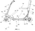
- FIG. 1 illustrates a side view of a motorized vehicle 101 in an operational configuration, according to some embodiments of the present invention.
- the term operational configuration is used herein to comprise a sitting configuration and/or a standing configuration, when the motorized vehicle is open rather folded, and can be used for transportation.
- the motorized vehicle 101 is composed of a steering rod 105, a front lower chassis 125, a rear lower chassis 145, and an upper chassis 170 which are connected using bearings.
- bearings For example, three bearings, a front bearing 140, a middle bearing 165 and a rear bearing 175, connect these parts, allowing a compact folding configuration, for instance as described below.
- a foot surface 198 may be mounted on the lower chassis 125, 145.
- the motorized vehicle 101 has a steering rod 105.
- the steering rod 105 has a bottom side 110 and a top side 115.
- One or more front wheel(s) 120 is connected to the bottom side 110.
- the front wheel may include a brushless wheel hub motor.
- the brushless wheel hub motor may be electrically motorized by one or more batteries mounted on the front and/or rear lower chassis.
- the batteries are mounted on two sides of the front lower chassis 125.
- the batteries are mounted on two sides of the back lower chassis.
- a front lower chassis 125 is hinged to the bottom side 110.
- the front lower chassis 125 has a front lower chassis upper side 127 and a front lower chassis lower side 129.
- a front bearing 140 connects the front lower chassis 125 and the bottom side 110 to each other.
- a rear lower chassis 145 is hinged to the front lower chassis 125.
- the rear lower chassis 145 has a rear lower chassis lower side 150 and rear lower chassis upper side 155.
- At least two rear wheels 160 are connected to the rear lower chassis 145.
- the rear wheels 160 may be dynamically connected to the rear lower chassis 145 by retraction links 196 and wheel arms 190.
- the rear wheels 160 may be motorized by a brushless wheel hub motors.
- the brushless wheel hub motors may be electrically motorized, for example as the front wheel.
- the wheel arms 190 may enable a diagonal movement of the rear wheels 160 with respect to the rear lower chassis 145. This movement creates a bigger distance between the rear wheels 160.
- the distance between an axis passing through the centers of the rear wheels 160 and the front wheel 120 is reduced when the rear wheels 160 are retracted towards said lower chassis 125 in this diagonal movement.
- the distance between the rear wheel(s) 160 and the front wheel(s) 120 may not be reduced when said rear wheel(s) 160 are retracted towards the lower chassis 145.
- the bigger rear wheels distance may enable supporting higher weight individuals, by increasing stability.
- the rear wheels' 160 movement may enable compliance with mobility scooter regulations by having a larger distance between the rear wheels 160.
- Exemplary motorized vehicle regulations are: EN12184, ANSI/RESNA WC-1 and/or ANSI/RESNA WC-2.
- a middle bearing 165 connects the front lower chassis 125 and said rear lower chassis 145 to each other.
- the middle bearing 165 may automatically trigger folding of the front bearing 140 and/or the rear bearing 175.
- the automatic trigger may enable folding the motorized vehicle 101 with one hand by a human operator.
- An upper chassis 170 is hinged to the rear lower chassis 145.
- a rear bearing 175 connects the upper chassis 170 and the rear lower chassis 145 to each other.
- the motorized vehicle 101 is taken from an operational configuration to a folded configuration by maneuvering the top side 115 of the steering rod 105 towards the front lower chassis upper side 127, the front lower chassis lower side 129 towards the rear lower chassis lower side 150 and the upper chassis 170 towards the rear lower chassis upper side 155.
- the folding outcome is depicted in FIG. 3 and further described below.
- the motorized vehicle 101 may have a back rest 185 and a seat base 187. Close proximity of the back rest 185 and the seat base 187 is achieved by folding the back rest 185 towards the seat base 187 and/or by folding the seat base 187 towards the back rest 185.
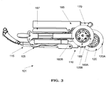
- FIG. 3 illustrates a side view of a motorized vehicle in a folded configuration, according to some embodiments of the present invention.
- the motorized vehicle 101 is as depicted in FIG. 1 .
- the elements numbering scheme corresponds to the elements numbering scheme of FIG. 1 .
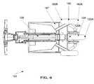
- the front wheel 120 may be in close proximity to at least two rear wheels 160 when the motorized vehicle 101 is in folded configuration.
- the front wheel 120 has a front wheel bottom 120A and a front wheel top 120B.
- the rear wheel 160 has a rear wheel bottom 160A and a rear wheel top 160B.
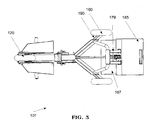
- FIG. 4 illustrates a bottom view of a motorized vehicle in an operational configuration, according to some embodiments of the present invention.
- the motorized vehicle 101 is as depicted in FIG. 1 .
- the elements numbering scheme corresponds to the elements numbering scheme of FIG 1 .
- the lower chassis 124 has a latitudinal axis 188. The distance between each rear wheel and the latitudinal axis is reduced by the wheel retraction.
- the retraction of the rear wheels 160 may be performed simultaneously.
- the retraction of the rear wheels 160 may be performed symmetrically with respect to the latitudinal axis 188.
- the rear wheels 160 are retracted along a plurality of different diagonals which converge towards a point on the longitudinal axis.
- the rear wheels 160 remain essentially parallel to one another during the retraction.
- FIG. 5 illustrates a bottom view of a motorized vehicle in an intermediate configuration between an operational configuration and a folded configuration, according to some embodiments of the present invention.
- the motorized vehicle 101 is as depicted in FIG. 1 .
- the elements numbering scheme corresponds to the elements numbering scheme of FIG 1 .
- FIG. 6 illustrates a bottom view of a motorized vehicle in a folded configuration, according to some embodiments of the present invention.
- the motorized vehicle 101 is as depicted in FIG. 1 .
- the elements numbering scheme corresponds to the elements numbering scheme of FIG 1 .
- FIG. 7 is a top view illustration of a folding chassis coupled to a wheel retraction and extraction mechanism, according to some embodiments of the present invention.
- FIGs. 7-10 illustrate a process of folding a motorized vehicle. The process begins by folding the seat and retracting the rear wheels. Then the handle 732 is lifted and the puller 1333 is pulled. The handle 732 is connected to a middle bearing 765. The middle bearing 765 connects between a front lower chassis 725 which is mechanically connected to the front wheel 720 and a rear lower chassis 745A, 745B that is mechanically connected to the rear wheels 760. The pulling approximates between the front lower chassis 725 and the rear lower chassis 745A, 745B.
- the curved lever 730 is connected to an actuator 795 which is connected to retraction links 796.
- the actuator 795 and retraction links 796 in this example are inside the lower chassis.
- the retraction links 796 are connected to wheel arms 790.
- the wheel arms 790 are connected to the rear wheels 760.
- the pushing of the lever 730 pulls the wheel arms 790, optionally diagonally, shortening the distance between one rear wheel 760 to another and between the rear wheel 760 and the rear lower chassis 745A, 745B. As the pulling simultaneously approximates between the front lower chassis 725 and the rear lower chassis 745A, 745B, the rear 760 and the front wheels 720 are maneuvered toward one another.
- the wheel retraction and extraction mechanism 796 has an actuator 795, internal retraction links 796 and wheel arms 790 that pull the rear wheels 760 towards lower chassis 724.
- the motorized vehicle 701 has a chassis.
- the chassis is made of an upper chassis 770 and a lower chassis 724.
- the lower chassis 724 is made of a front lower chassis and a rear lower chassis. The two lower chassis parts are connected by a bearing 765.
- the folding of the upper chassis 770 towards the lower chassis 724 drives the movement of the wheel retraction and extraction mechanism.
- the lever 730 drives the actuator 795 along the straight section of the rear lower chassis 745B.
- the moving actuator 795 pulls the retraction links 796 which pull the wheel arms 790.
- the retraction links 796 moves from the angled part of the rear lower chassis 745A to the straight part of the rear lower chassis 745B.
- the movement of the wheel arms enables change(s) in width, length, diagonal movement, V-shaped movement, Y-shaped movement and/or a combination thereof between the rear wheels 760 and the rear lower chassis 745.
- the upper chassis 770 folds towards the actuator 795.
- the wheel retraction of a motorized vehicle of 580 mm width, 1138 mm length, 868 mm height, 203 mm wheel diameter is between about 60 mm and about 120 mm width, and between about 60 mm and 200 mm in length.
- the actuator 795 and the lever 730 move the rear wheel 760 diagonally towards the lower chassis 724.
- the diagonal movement may be at an angle of about 25 to 65 degrees with respect to the rear lower chassis 745.
- the motorized vehicle 701 has at least one front wheel 720.
- the folded motorized vehicle 701 has a foot rest 722.
- the motorized vehicle 701 further comprises a folding seat 786.
- the folding seat 786 may be mounted on the upper chassis 770. Folding of the folding seat 786 may drive the contraction of the upper chassis 770.
- the lower chassis 724 has a front lower chassis 725 and a rear lower chassis 745A, 745B and a bearing connects the front lower chassis with the rear lower chassis.
- FIG. 8 is a bottom view illustration of a folding chassis back part coupled to a wheel retraction and extraction mechanism in an operational configuration, according to some embodiments of the present invention.
- the seat folding and the wheel retraction and extraction mechanisms are as depicted in FIG. 7 .
- the curved lever 830 and the seat base 887 are viewed from below.
- the rear wheels 860 are depicted in an operational configuration.
- the wheel arms 890 are in furthest position with respect to the lower chassis 824.
- FIG. 9 is a bottom view illustration of a folding chassis back part coupled to a wheel retraction and extraction mechanism in an intermediate configuration, according to some embodiments of the present invention.
- the seat folding and the wheel retraction and extraction mechanisms are as depicted in FIG. 7 .
- the rear wheels 960 are depicted in an intermediate position between an operational configuration and a folded configuration.
- the wheel arms 990 are closer to the lower chassis 924 with respect to their position as depicted in FIG 8 .
- FIG. 10 is a bottom view illustration of a folding chassis back part coupled to a wheel retraction and extraction mechanism in a folded configuration, according to some embodiments of the present invention.
- the seat folding and the wheel retraction and extraction mechanism are as depicted in FIG. 7 .
- the rear wheels 1060 are depicted in a folded configuration.
- the front wheel 1020 has a front wheel bottom 1020A and a front wheel top 1020B.
- the rear wheel 1060 has a rear wheel bottom 1060A and a rear wheel top 1060B.
- the wheel arms 1090 are in the closest position to the lower chassis 1024.
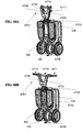
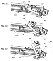
- FIGs. 11A-11L are images illustrating the back part of the motorized vehicle in operational, intermediate and folded configurations from four different view points, according to some embodiments of the present invention.
- FIGs. 11A, 11B and 11C illustrate the back part of the motorized vehicle from a side view in operational, intermediate and folded configurations respectively.
- FIGs. 11D, 11E and 11F illustrates a side section of the back part of the motorized vehicle in an operational, intermediate and folded configurations respectively configuration.
- FIGs. 11G, 11H and 11I illustrate the back part of the motorized vehicle from a bottom view in operational, intermediate and folded configurations respectively.
- FIGs. 11J, 11K and 11L illustrate the back part of the motorized vehicle from a rear view in operational, intermediate and folded configurations respectively.
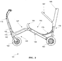
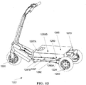
- FIG. 12 illustrates a motorized vehicle 1201 in a standing configuration, according to some embodiments of the present invention.
- the motorized vehicle 1201 has at least two configurations, namely a sitting configuration and a standing configuration, and optionally a third configuration, the folded configuration.
- the transition of the motorized vehicle 1201 from the sitting configuration to the standing configuration or vice versa may be accomplished by folding the seat base 1287 and the upper chassis 1270.
- the folded back rest 1285 is used as a standing platform in the standing configuration.
- the rear wheels 1260 may be retracted using a wheel retraction and extraction mechanism as described in FIGs. 7-10 .
- the motorized vehicle 1201 has a chassis 1224, one or more rear wheel(s) 1260 and at least one front wheel 1220.
- the seat base 1287 is hinged to the backrest 1285 by a bearing 1289.
- the seat base 1287 is essentially perpendicularly positioned with respect to the backrest 1285 when the motorized vehicle 1201 is in a sitting configuration.
- the seat base 1287 is essentially parallel to the backrest 1285 when the motorized vehicle 1201 is in standing configuration.
- the seat base 1287 is in close proximity to the chassis when the motorized vehicle 1201 is in standing configuration.
- the seat base 1287 position change may be achieved by the upper chassis folding device depicted in FIG. 16 .
- the seat base 1287 may have a seat base back side 1287B and a seat base seat support side 1287A.
- the seat base back side 1287B may fit in size and/or shape to the lower chassis.
- the backrest 1285 may have a backrest back support side 1285A and a backrest back side1285B.
- the seat base seat support side 1287A and/or the backrest back support side 1285A may fit a sitting position of a human operator.
- the backrest back side 1285B size and/or shape may fit a standing mode of a human operator.
- the backrest back side 1285B may be flat and/or may have a rough gripping surface for preventing sliding and increasing traction.
- the motorized vehicle 1201 may have a wheel moving mechanism 1292 which pushes at least one rear wheel 1260 away from the chassis 1224 when the motorized vehicle 1201 is in sitting configuration and retracts at least one rear wheel 1260 when the motorized vehicle 1201 is in standing configuration.
- the motorized vehicle may comprise a seat locking mechanism, which restricts the movement of the seat base 1287 when the motorized vehicle is in at least one of the sitting configuration and standing configuration.
- the seat locking mechanism allows the movement of the seat base and the backrest when the scooter transitions between the sitting configuration and the standing configuration.
- the seat locking mechanism may be mounted on the backrest 1285.
- the motorized vehicle may comprise a chassis locking mechanism, which restricts the movement of the upper chassis with respect to the lower chassis when the motorized vehicle is in at least one of the sitting configuration, folded configuration and standing configuration.
- the chassis locking mechanism allows the movement of the upper chassis 1270 and the lower chassis when the scooter transitions between the sitting configuration, folded configuration and the standing configuration.
- the chassis locking mechanism may be mounted on the backrest 1285.
- FIG. 13 illustrates a locked state of a central lock and release mechanism for a motorized vehicle 1301 in a folded configuration, according to some embodiments of the present invention.
- the rocker 1335 has a fork hook 1336, a first rear lower chassis hook 1337 and a second rear lower chassis hook 1338.
- the first 1337 and second 1338 rear lower chassis pins are mounted on said rear lower chassis 1345.
- the first 1337 rear chassis hook 1337 is hooked to a pin 1331.
- the first 1337 and second 1338 rear lower chassis hooks hook onto the first 1537A and second 1538A rear lower chassis pins, respectively.
- the steering rod 1305 is hinged to the front lower chassis 1325.
- the front lower chassis 1325 is hinged to the rear lower chassis 1345.
- a rocker 1335 that pivots around an axis 1334.
- the rocker 1335 hooks onto the fork 1339 on one end and the rear lower chassis 1345 on the other end as further described in FIG. 15 .
- the rocker 1335 is pivoted in the locking direction using a spring which is not shown in this illustration. Lifting the puller 1333, which is located on the handle 1332, pulls at pin 1338B and releases the two hooks 1336, 1337 simultaneously and allows the front lower chassis 1325 and the rear lower chassis 1345 to fold.
- the front lower chassis 1325 and the rear lower chassis 1345 are free to move from an operative configuration to a folded configuration.
- the puller 1333 moves the flange 1395, via a mechanical connection, against a flange spring.
- the flange spring is connected to the flange and rear lower chassis, and the flange 1395 is mechanically connected to the rear lower chassis 1345.
- the flange 1395 pulls against the first rear lower chassis hook 1337.
- the first rear lower chassis hook 1337 pivots the rocker 1335 for releasing.
- the front lower chassis 1325 and the rear lower chassis 1345 are parallel to each other.
- a the first rear lower chassis hook 1337, in the rocker 1335 latches over the first rear lower chassis pin 1337A in the rear lower chassis 1345 and prevents the front lower chassis 1325 and the rear lower chassis 1345 from separating.
- a geometric lock 1340 between the rocker 1335 and fork 1339 prevents the steering rod 1305 from tilting.
- lifting the puller 1333 moves the flange 1395 against a spring which is not shown.
- the flange 1395 pulls at the first rear lower chassis hook 1337 which pivots the rocker 1335 and releases the front lower chassis 1325 and the rear lower chassis 1345.
- the released rocker 1335 releases two locks: the spring pivots the rocker 1335 so that the rocker 1335 pushes against the fork 1339 and prevents it from rotating about its axis 1399.
- a rear lower chassis 1345 is locked by the rocker 1335.
- the rocker 1335 pivoting releases the chassis and steering rod 1305 thereby allowing the front lower chassis 1325 and the rear lower chassis 1345 to align at an approximately horizontal position.
- two rockers1335 are positioned on both sides of the front lower chassis 1325.
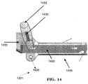
- FIG. 14 illustrates a central lock and release mechanism for simultaneous operation of two locks in an operational motorized vehicle, in a locked state, according to some embodiments of the present invention.
- the central lock and release mechanism 1301 is as depicted in FIG. 13 .
- the elements numbering scheme corresponds to the elements numbering scheme of FIG. 13 .
- the handle 1432 is moved by a human operator for folding the mobility scooter.
- the handle 1432 moves towards the rocker 1435 which in turn moves the puller 1433.
- the rocker moves around the axis 1334 and the front lower chassis moves around the chassis hinge 1426. When the front lower chassis moves around the chassis hinge 1426 it is folded towards the rear lower chassis lower side 1455.
- FIG. 15 illustrates a central lock and release mechanism for simultaneous operation of two or more locks as part of a motorized vehicle front in an operational configuration, according to some embodiments of the present invention.
- the central lock and release mechanism is as depicted in FIG. 13 .
- the elements numbering scheme corresponds to the elements numbering scheme of FIG 13 .
- the release is made by the release of the pin 1536A.
- the released fork 1539 along with the steering rod 1505 and the front wheel 1520 can move towards the lower side of the rear lower chassis 1555 to their folded position when the handle 1532 is pulled up.
- a spring operated on said rocker 1535 to lock said rear lower chassis 1555 and said steering rod 1505.
- FIG. 16 illustrates a side view of an upper chassis folding device 1601, according to some embodiments of the present invention.
- An arm 1671 is mechanically connected to the upper chassis 1670.
- a curved lever 1672 having a curved channel 1673 is mechanically connected to a rear lower chassis 1645.
- the mechanical connection between the chassis and the curved lever 1672 may comprise an actuator 1695.
- the actuator 1695 is pushed inside along the chassis upon folding of the upper chassis folding device 1601.
- the arm 1671 is engaged in the curved channel 1673.
- the arm is essentially continuing the curved lever 1672.
- the arm 1671 is mechanically connected to the upper chassis 1670.
- the mechanical connection between the arm 1671 and the upper chassis 1670 may comprise a multiplicity of arms connected by a multiplicity of hinges.
- An arm 1671 and/or a set of arms and hinges 1671 is mechanically connected to the back rest 1685.
- the arm 1671 and the curved lever 1672 elevate the seat base 1687 indirectly in a sitting configuration compared to a standing configuration.
- the back rest 1685 has channels and the upper chassis has roads 1670A.
- the back rest 1685 glides over the upper chassis 1670 by the movement of the backrest 1685 channels over the upper chassis roads 1670A.
- the back rest 1685 channels encircle the upper chassis roads 1670A.
- the gliding of the back rest 1685 may be enabled by the movement of the arm 1671 in the curved lever 1672.
- the upper chassis folding device comprises a back rest 1685 mounted on the upper chassis 1670 and a seat base 1687 hinged to the back rest 1685.
- the seat base 1687 hangs over the rear lower chassis 1645.
- the seat base 1687 may have an orthopedic shape capable of supporting a heavy weight person for about 12 hours in a row without causing discomfort.
- the upper chassis folding device 1601 comprises a lock between the back rest 1685 and the seat base 1687.
- the back rest 1685 has a release button 1686.
- the release button 1686 allows the seat base 1687 and the back rest 1685 to fold towards each other and towards the rear lower chassis 1645.
- the lock is re-engaged when the back rest 1685 and the seat base 1687 and the rear lower chassis 1645 are parallel in a folded position.
- an additional hinged arm is connected to the seat base 1687.
- the additional hinged arm keeps the seat base 1687 parallel to the ground as the seat base 1687 is hanged over the rear lower chassis 1645 in an open position when the motorized vehicle is in an operational configuration and while the mobility scooter is transitioned from sitting configuration to standing configuration.
- the upper chassis folding device 1601 is locked and released by a locking mechanism comprising a disc, which is mounted on the actuator 1695, with one or more pins.
- the disc's pins fit into apertures of the rear lower chassis 1645.
- the actuator 1695 moves the upper chassis folds and the disc moves along with the actuator 1695.
- the pins on the disc fit into a different set of apertures in the rear lower chassis 1645.
- a wire connecting the release button 1686 to the actuator may be used to control the lock.
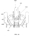
- FIG. 17 illustrates an angled rear view of an upper chassis folding device during folding, according to some embodiments of the present invention.
- the upper chassis folding device is as depicted in FIG. 16 .
- the upper chassis folding device is depicted here during the folding process.
- the arm 1771 is posited further down the curved channel 1773 with respect to its position 1671 in FIG. 16 .
- the arm's 1771 position enables the back rest 1785 gliding over the upper chassis 1770.
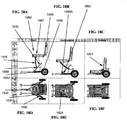
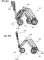
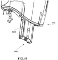
- FIGs. 18A-18F are images illustrating rear parts of a motorized vehicle 1801 with a bearing and a wheel retraction apparatus, according to some embodiments of the present invention.
- FIGs. 18A, 18B and 18C illustrate a side view of a sitting, intermediate and folded configurations respectively.
- FIGs. 18D, 18E and 18F illustrates a bottom view of the sitting, intermediate and folded configurations respectively.
- the motorized vehicle 1801 seat 1886 and upper chassis 1845 folding triggers the rear wheels 1860 retraction.
- the motorized vehicle 1801 is as described in FIG. 20 .
- the motorized vehicle 1801 folding begins with lowering the chair 1886.
- the chair 1886 may be in a folded configuration or in an open configuration when lowered.
- the chair 1886 has a base 1887 and a back rest 1885.
- the chair 1886 is lowered by the movement of the upper chassis 1845 towards the lower chassis. This movement is possible by multiple bearings 1889 connecting the upper 1845 and lower 1824 chassis. In this example, the movement is enabled by four bearings constituting a parallelogram.
- the lever 1830 moves along with the upper chassis.
- the lever's 1830 movement triggers the rear wheels 1860 retraction by the wheel retraction apparatus 1892.
- the wheel retraction apparatus 1892 has an actuator 1895, two retraction links 1896 and wheel arms 1890.
- the wheel retraction apparatus 1892 has at least one actuator 1895, at least one retraction link 1896 and at least one wheel arm 1890.
- the retraction links 1896 are external to the lower chassis 1824.
- the retraction links 1896 are optionally spread in a V shaped arrangement and/or a Y shaped arrangement.
- the movement of the retraction links 1896 may be limited by a Y shaped track.
- the retraction links position is interior to the lower chassis 1824 and/or integral within the lower chassis.
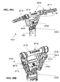
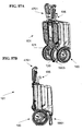
- FIGs. 19A-19F are images illustrating a motorized vehicle 1901 with a bearing and a wheel retraction apparatus, according to some embodiments of the present invention.
- FIGs. 19A, 19B and 19C illustrate a side view of a sitting, intermediate and folded configurations respectively.
- FIGs. 19D, 19E and 19F illustrates a bottom view of the sitting, intermediate and folded configurations respectively.
- the motorized vehicle 1901 seat 1986 and upper chassis 1945 folding triggers the rear wheels 1960 retraction.
- the motorized vehicle 1901 is as described in FIG. 21 .
- the motorized vehicle 1901 folding begins with folding the chair 1986.
- the base which is not depicted in the illustration, is folded towards the back rest 1985.
- the upper chassis is folded towards the lower chassis 1924 by the bearing 1989.
- the lever 1930 triggers the rear wheels 1960 retraction by the wheel retraction apparatus 1992.
- the wheel retraction apparatus 1992 has an actuator 1995, two retraction links 1996 and two wheel arms 1990.
- the retraction links 1996 located internally to the V shaped lower chassis 1924.
- the lever 1930 rotates the actuator 1995.
- the rotating actuator 1995 pulls with it the retraction link 1996.
- the retraction link 1996 then pulls the rear wheels 1960.
- the rear wheels 1960 move diagonally towards the folded lower chassis 1945.
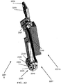
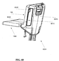
- FIG. 20 illustrates a back part of a motorized vehicle 1801 with a tunneled 1895A actuator 1895 and a linear lever 1830, according to some embodiments of the present invention.
- the seat 1886 has a base 1887 and a backrest 1885.
- An upper chassis 1845 is connected to the base 1887 by a system of bearings 1889.
- An essentially linear lever 1830 is connected to the upper chassis 1845 on one side and to the actuator 1895 on the other side.
- the actuator 1895 has a tunnel 1895A.
- the rear wheels 1860 connect to retraction links 1896.
- the rear wheels 1860, wheel arms 1890, retraction links 1896 and actuators 1895 move symmetrically on both sides of the lower chassis 1824.
- the folding movement and folding sequence of the motorized vehicle 1801 are as described in FIG. 18 .
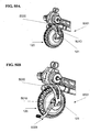
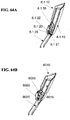
- FIG. 21 illustrates a back part of motorized vehicle 2101 having an angled lever 2130, according to some embodiments of the present invention.
- the angled lever 2130 connects the upper chassis 2145 to the actuator 2195.
- the actuator 2195 may be V-shaped.
- the angle of the angled lever 2130 is between 100 degrees and 170 degrees.
- FIG. 22 illustrates a central lock and release mechanism 2201 mounted on a motorized vehicle's lower chassis, according to some embodiments of the present invention.
- Each lock 2301, 2202 may be positioned on both right 2201A and left 2201B sides of the vehicle.
- the locks 2301, 2202 are connected by an angular rod 2349 which is a motion transferring element.
- the locks 2301, 2202 are mounted, in this example, on the lower chassis.
- the steering rod lock 2202 connects the steering rod to the front lower chassis.
- the lower chassis lock 2301 connects the front lower chassis to the rear lower chassis.
- the motorized vehicle is folded by lifting the handle 2232.
- the handle 2232 lifts the puller 2233 and the puller 2233 opens the lower chassis lock 2301.
- the lower chassis lock 2301 moves the angled rod 2349.
- the angled rod 2349 transfers the motion and opens the steering rod lock 2202.
- the angles of the rod 2349 may be designed to simultaneously open the two locks 2301, 2202.
- the steering rod lock 2202 has two knobs 2305 and the lower chassis lock 2301 has one knob 2305.
- a higher number of knobs 2305 may contribute to the strength of the lock and its ability to maintain a configuration under physical pressure.
- Multiple knobs may restrict the freedom of movement for the concentric elements 2310, 2320 and/or 2330.
- the number of knobs is half the number of apertures on a single concentric element 2310, 2320 and/or 2330.
- the number ratio between knobs and recesses can be chosen to change the number of locking positions, the angles of locking positions and/or the freedom of movement the lock allows.
- the two locks 2301, 2202 are as described in FIG. 23 .
- rod's 2349 shape may serve to transfer motion from one lock to the other.
- the rod may be: a linear rod, a non-linear rod having at least one curve, a non-linear rod having a plurality of angles and a plurality of curves and/or a plurality of segments mechanically connected to one another. Each segment can be as described above.
- the order of locks operated by the central lock and release mechanism 2201 may be reversed: the puller opens the steering rod lock 2202 first.
- the rod 2349 transfers the motion to the lower chassis lock 2301.
- the locks are simultaneously opened by the puller movement.
- FIG. 23 illustrates a lower chassis lock, according to some embodiments of the present invention.
- This lock 2301 may be also used to lock the steering rod.
- the lock mechanism is based on one or more knobs 2305 which transfer between apertures 2311, 2321, 2331 of at least three concentric elements: the fold axis 2310, the collar 2320 and the flange 2330.
- the collar 2320 scoops up one or more knobs 2305 from an aperture 2311, 2321 and/or 2331. When the collar 2320 moves the knob 2305 moves along with it until the knob 2305 is deposited at the another aperture 2311, 2321 and/or 2331.
- each of the three concentric elements 2310, 2320, 2330 may be on a shared plane.
- the apertures 2311, 2321 and/or 2331 are aligned the knob can transfer easily from one element to the other and the parts statically attached to the fold axis 2310 and the flange 2330 can change position.
- the statically attached parts may be the front lower chassis 125 and the rear lower chassis 145.
- the aligned apertures 2311, 2321 and/or 2331 may allow the folding and/or unfolding of a motorized vehicle 101.
- the knob 2305 cannot move through aperture 2331, thereby locking the entire mechanism 2301 and the parts statically attached to them 2325, 2345.
- the collar 2320 may prevent the knob(s) 2305 from moving out of the fold axis 2310.
- the fold axis 2310 has a plurality of fold axis apertures 2311.
- the fold axis 2310 may be mounted on the lower chassis 2325.
- the mounting of the fold axis 2310 on the lower chassis 2325 may be fixed, thereby creating a single rigid body that moves as one unit.
- the fold axis 2310 may be mounted on said rear lower chassis 2345 and said flange 2330 may be mounted on said front lower chassis.
- a flange 2330 has a flange disc 2333 and a flange sleeve 2332.
- the flange has a plurality of flange apertures 2331.
- the collar 2320 encircles the flange sleeve.
- the collar 2320 has a plurality of collar apertures 2321.
- One or more knobs 2305 occupy the apertures 2311, 2321, 2331.
- a single knob 2305 occupies each aperture set: a fold axis aperture 2311a collar aperture 2321, and a flange aperture 2331.
- the top of the flange aperture 2331 is partially visible in this FIG.
- some of the apertures 2311, 2321, 2331 are not occupied by a knob.
- the diameter of each knob 2305 is smaller than the diameter of each flange aperture 2331.
- the fold axis 2310 and collar 2320 may rotate around a common axis 2348.
- the knob 2305 moves from fold axis apertures 2311 to the collar apertures 2321.
- the rotation of the collar 2320 may be transferred to another lock mechanism such as 2202.
- the movement may be transferred by an angled non-linear rod 2349.
- the rod may be a linear rod, a non-linear rod with a single and/or multiple curves, and/or non-linear rod with a combination of angles and curves.
- the angular rod 2349 may be connected to the fold axis 2310 and/or to the collar 2320.
- the locations of the fold axis 2310 and the collar 2320 are switched, for example, the collar 2320 is essentially centrally located with respect to the flange sleeve 2332 and the flange sleeve 2332 essentially encircles the collar 2320.
- additional essentially concentric elements other than the fold axis 2310, the collar 2320 and the flange 2330 comprise the lower chassis lock.
- the knob harboring parts, for example the fold axis 2310, the collar 2320 and/or the flange 2330 may be arranged in a non concentric fashion.
- a fold axis 2310, a collar 2320 and a flange 2330 which have essentially the same diameter and are positioned behind one another and the apertures of the fold axis and the flange are in different positions.
- a cover is mounted on the lower chassis lock 2301. The cover may hold the collar in its position. The cover may protect the lock 2301 against dust, dirt and other mechanism blockers.
- FIGs. 24A-24C images illustrating the folding process of a rear part of a motorized vehicle 2401 having a channeled 2485A backrest 2485 which glides over an upper chassis road 2445A, according to some embodiments of the present invention.
- the motorized vehicle 2401 and the manner of its folding is as described in FIG. 25 .
- FIG. 24A illustrates a sitting configuration of the motorized vehicle 2401.
- FIG. 24B illustrated an intermediate configuration of the motorized vehicle 2401 upon folding.
- the backrest 2485 glides partially over the upper chassis 2445.
- FIG. 24C illustrates a folded configuration.
- the backrest 2485 covers the major part of the upper chassis 2445.
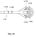
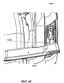
- FIG. 25 illustrates the rear part of a motorized vehicle 2501 having a channeled 2585A backrest 2585 which glides over an upper chassis road 2545A, according to some embodiments of the present invention.
- the backrest 2585 and the upper chassis 2545 are pushed forward around the seat bearing 2580.
- the movement of the upper chassis 2545 causes the lever 2530 to move forward and moves the back rest 2585.
- the backrest 2585 is pulled by the arm and hinges system 2590 and the lever 2530 toward the upper chassis 2545 and over the upper chassis 2545.
- the lever 2530 moves forward and pivot about the rear link 2590A.
- the front link 2590B moves up in relation to the rear link 2590A, pivoting the top link 2590C around the top link - rear link 2590A axis.
- the motion pulls the backrest 2585 towards the upper chassis 2545 and is completed when the backrest 2585 and the upper chassis 2545 are parallel to the lower chassis 2524.
- the motorized vehicle 2501 also has a wheel retraction apparatus 2392.
- the movement of the lever 2530 which induces the gliding of the backrest 2585 over the upper chassis 2545 also pulls the retraction links 2596 which pull the wheel arms 2590.
- the wheels arms 2590 retract the rear wheels 2560 bringing them closer to the lower chassis 2524.
- FIG. 26 is a section of half a steering rod lock 2202 with aligned apertures, according to some embodiments of the present invention.
- the lock is as depicted in FIG. 23 .
- the lock is applied to the steering rod instead of the lower chassis.
- the aligned apertures create an open lock configuration which allows the static parts, front lower chassis and steering rod, connected to the lock 2601 to change their position toward one another.
- the lock is comprised of a fold axis 2610, a collar 2620 and a flange 2630.
- the lock 2601 has two knobs 2605 which occupy the flange apertures 2631, fold axis apertures 2611 and/or the collar apertures.
- the apertures 2611, 2631 are aligned, enabling the knobs 2605 to pass between the fold axis 2611 and the collar aperture through the flange aperture 2631.
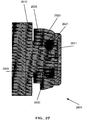
- FIG. 27 is a section of half a lower chassis lock with unaligned apertures, according to some embodiments of the present invention.
- the lock 2601 is as depicted in FIG. 26 with the fold axis apertures 2611 and the collar apertures in an unaligned position which prevent the knob from moving through the flange aperture 2631.
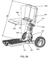
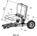
- FIG. 28 is an image illustrating an operational configuration of the rear part of the motorized vehicle 101 having a mechanical seat folding arrangement 2805, according to some embodiments of the present invention.
- the motorized vehicle 101 is as presented in FIGs. 1-22 and 24-25 .
- the mechanical seat folding arrangement 2805 moves the seat 1886 along the lower chassis 145.
- the movement of the seat 1886 along the lower chassis 145 may be retracting the seat 1886 towards the rear wheels client management module 160 and/or advancing the seat 1886 towards the front wheel 120.
- the mechanical seat folding arrangement 2805 also shortens the distance between the seat 1886 and the chassis connection 3110 as illustrated in FIG. 29 .
- shortening the distance between the seat 1886 and the chassis connection 3110 is performed independently of the mechanical seat folding arrangement's 2805 operation.
- the chassis connection 3110 connects the upper chassis to the lower chassis 145.
- the back rest 185 is positioned in proximity to other elements 187, 145.
- the back rest 185, seat base 187 and rear lower chassis 145 are proximate to each other and/or the back rest 185 and seat base 187 are proximal to each other.
- the mechanical seat folding arrangement's 2805 operations, folding, shortening and/or moving, may be performed in a single motion.
- the combined motion of shortening the distance to the chassis connection 3110 and moving the seat 1886 aligns a back rest lateral front 185A with the seat base lateral front 187A, thereby creating a boxed shape of the motorized vehicle in a folded configuration.
- the boxed shape may have large planar surfaces and/or be free of extrusions and recesses.
- the boxed shaped may resemble a carried suitcase.
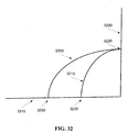
- the motion of the back rest lateral front 185A during the combined motion creates a modified arched path 3210 illustrated in FIG. 32 .
- FIG. 32 illustrates two paths 3205 and 3210 of a back rest lateral front 185A.
- two axes are shown: axis 3220 essentially parallel to the upper chassis 170 in an operational configuration and axis 3215 essentially parallel to the rear lower chassis 145 in an operational configuration.
- the paths 3205 and 3210 illustrate the movement of the back rest lateral front 185A from a position in an operational configuration 3225 to a position in the folded configuration 3230 and/or 3235.
- the path creates a curve between an axis 3220 essentially parallel to the upper chassis 170 in an operational configuration and an axis 3215 essentially parallel to the rear lower chassis 145.
- the path ends at a location 3230 according to the dimensions of the upper chassis 170, the back rest 185 and connection means between the seat 1886 and the upper chassis 170.
- the path generated by such a location 3230 is an unmodified arched path 3205.
- the unmodified arched path 3205 is a perfect radial.
- the path 3205 is modified.
- the location 3230 of the back rest lateral front 185A in a folded configuration of the motorized vehicle, when the back rest 185 is retracted is more proximate to the rear wheels compared to the location 3235 of the back rest lateral front 185A in a folded configuration of the motorized vehicle, without back rest 185 retraction.
- the retraction of the back rest 187 brings the back rest lateral front 185A closer to the rear wheels 160 along the rear lower chassis 145.
- the back rest 185 retraction created a modified arched path 3210 ending 3235 at a shorter distance from the upper chassis 170 and/or the rear wheels 160 compared to the unmodified path 3205.
- the upper chassis 170 comprises two beams: a rotating beam 3120 and a linear beam 3130.
- the linear beam 3130 is connected to the seat 1886.
- the rotating beam 3120 is connected to the lower chassis 145 through the chassis connection 3110.
- the rotating beam 3120 rotates around the chassis connection 3110.
- the linear beam 3130 may slide along the rotating beam 3120 for performing seat 1886 shortening as described above. Sliding may occur using tracks.
- the joint movement of the two beams 3120, 3130 creates the arch movement as illustrated in FIG. 32 .
- the motion created by the mechanical seat folding arrangement 2805 decreases at least one dimension of the folded configuration, rendering the folded configuration more compact for carrying, storage and/or handling.
- the distance between the back rest lateral front 185A and the rear lower chassis 145 in an operational configuration is bigger than the same distance in a folded configuration. For example, the distance changes from 764 centimeters in the operational configuration to 306 centimeters (as illustrated by FIG. 28 and FIG. 30 respectively.
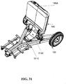
- FIG. 30 illustrates a folded configuration of the rear part of the motorized vehicle 101 having a mechanical seat folding arrangement 2805, according to some embodiments of the present invention.
- the motorized vehicle 101 is as presented in FIG. 28 .
- the folded configuration is achieved after the mechanical seat folding arrangement 2805 shifts the seat 1886 by both folding the seat 1886 and retracting the seat 1886.
- the backrest 185 retracts until the back rest lateral front 185A aligns with the seat base lateral front 187A.
- the back rest lateral front 185A and the seat base lateral front 187A form a single plane.
- the back rest lateral front 185A is distant between about 1 and about 10 centimeters from the seat base lateral front 187A.
- the back rest lateral front 185A is distant between about 5 and about 15 centimeters from the seat base lateral front 187A.
- a user pulls a seat folding trigger 3005 located in the backrest 185 and/or presses the release button 1686.
- the seat folding trigger presses a seat locking rod (not shown), positioned in an upper beam of the upper chassis 170, downwards towards the rear wheels 160.
- the seat locking rod pushes a rail knob (not shown) positioned in the upper beam, out of a rail lock socket (not shown) in a lower beam 3010 of the upper chassis 170.
- the rail lock socket Once the rail lock socket is unoccupied the upper beam is free to move on top of the lower beam using rail(s).
- the upper chassis 170 is lowered towards the rear lower chassis 145 thereby lowering the entire seat 1866 (backrest 185 and seat base 187).
- the seat 1886 moves along a bearing track 5.2 05.
- the bearing track may be positioned along the elongated dimension of the upper chassis 170.
- the lowering movement ends with the upper chassis extrusion 3015 close to the plane supporting the wheels 120, 160, for example, ground, a pavement, a floor etc.
- a mechanical seat folding arrangement 2805 translates the folding movement created by the user folding the motorized vehicle 101 into a motion of folding the seat 1886 along a modified arched path 3210. This motion combines an arched folding movement of the seat 1886 with a lateral movement of the seat 1886 and the upper chassis 170 toward the rear wheels 160. At the end of this combined motion the seat rest 185, seat base 187 and the upper chassis 170 are aligned. Optionally, the seat base 187 is folded towards the backrest 185 prior to lowering the seat 1886.
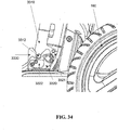
- FIG. 33 is an image illustrating a latching arrangement, according to some embodiments of the present invention.
- the mechanical seat folding arrangement 2805 which translates the folding movement of the seat into a modified arched path 3210 may be a latching arrangement 3301.
- the latching arrangement 3301 allows catching the upper chassis 170 and/or seat 1886 in a lowered position while performing the seat 1886 retraction.
- the latching arrangement comprises a latching arm 3310, a latching receiver 3330 and a catching arm 3320.
- the latching arm 3310 is connected by a latching arm hinge 3305 to the seat base 187.
- the latching arm 3320 has two bolts: a latching arm moving bolt 3311 and a latching arm caught bolt 3312.
- the latching arm caught bolt 3312 pushes against the catching arm front side 3321.
- the catching arm 3320 moves around a catching arm lower hinge bolt 3327, and the catching arm 3310 moves away from the latching socket 3335 of the latching arm receiver 3330.
- the movement of the catching arm 3320 is limited by a catching arm lower limiter bolt 3328.
- the latching arm caught bolt 3312 is latched by the latching socket 3335. Then, there is no pressure applied to the catching arm 3320 by the latching arm caught bolt 3312, and the catching arm 3320 moves back to its upright original position, thereby securing the latching arm caught bolt 3312 in the latching socket 3335.
- the latching arm catch bolt 3312 presses on the catching arm 3320.
- the catching arm 3320 tilts forward, as a result of pushing by the latching arm moving bolt 3311, along the latching arm.
- the forward tilt of the catching arm 3320 occurs around a catching arm upper hinge bolt 3325.
- the latching arm 3310 moves from the rear side of catching arm 3322 to the front side of the catching arm 3321, thereby passing the catching arm 3320 as illustrated in, as illustrated in FIG. 35 .
- the catching arm 3320 moves back to its upright position by a spring (not shown).
- the latching arm 3320 moves towards the catching arm 3310.
- the latching arm catch bolt 3312 pushes against the catching arm upper section 3323.
- a catching arm upper section 3323 moves a catching arm lower section 3324 by a set of connecting hinges 3325 -3328.
- the catching arm lower section 3324 moves away from the latching socket, thereby releasing the latching arm caught bolt 3312.
- the latching arm 3310 is free to move out of the latching socket 3335 and the seat 1886 may be lifted upwards for unfolding into an operational configuration.
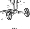
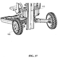
- FIGs. 36-39 illustrate a planetary gear 3901 shifting a seat 1886 of a motorized vehicle 101, according to some embodiments of the present invention.
- the motorized vehicle 101 and the mechanical seat folding arrangement 3901 are depicted in three states:
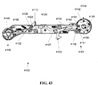
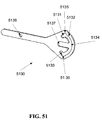
- FIG. 40 illustrates a transient locking and unlocking handle operated lock mechanism, according to some embodiments of the present invention.
- the locking mechanism 4101 enables a user to transiently operate a locking and unlocking handle.
- the transient operation may be, for example, pulling and then releasing a locking and unlocking handle 4110.
- the transient operation may be pushing and releasing or rotating and releasing.
- the brief transient nature of the operating the locking and unlocking handle 4110 enables a user to freely use his or her hands for operations other than locking and/or unlocking.
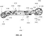
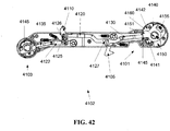
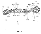
- a locking system 4102 of multiple locking mechanisms 4101, 4103 in a folding motorized vehicle ( FIGs. 41- 45 ), such as the locking mechanism described above 4101, are asynchronously locked and a synchronously released.
- the asynchronous lock and a synchronous release locking system 4102 locks each locked element once it reaches folded and/or operational positions locking points accordingly.
- the locked element may be, for example, a steering rod 105, a foot surface 198, a rear lower chassis 145 and/or a front lower chassis 125.
- a synchronizing arm 4120 coordinates and/or synchronizes the release of the locking mechanisms 4101, 4103.
- the locking mechanism 4102 is positioned along the front lower chassis 125.
- the transient locking and unlocking handle operated lock mechanism 4101 comprises: a locking wheel 4140, a bolt. 4130, a locking and unlocking handle 4110, and at least two rotating clamps 4150, 41 51.
- the locking wheel 4140 has a non unified radius.
- the non unified radius defines recesses 4145 and sections 4141, 4142 are between the recesses.
- the recesses lock a bolt 4130 which drives into and retracts from the recesses 4145.
- the rotation of the locking wheel 4140 is limited according to the different radii of the locking wheel's sections 4141, 4142.
- the non unified radius creates at least two bolt locking recesses 4145. Each section between two adjacent bolt locking recesses 4145 may have a unified radius.
- At least two sections 4141, 4142 are defined by the bolt locking recesses 4145: a small radius section 4141 and a big radius section 4142. As the name suggests, big radius section 4142 has a bigger radius than said small radius section 4141.
- a locking and unlocking handle 4110 is mechanically connected to the bolt 4130.
- the locking and unlocking handle 4110 is directly connected to the bolt 4130.
- the locking and unlocking handle 4110 is connected to the bolt 4130 via a set of connecting arms 4122 and hinges 4125, 4126.
- a synchronizing arm 4120 is part of the mechanical connection between the locking and unlocking handle 4110 and the bolt 41.
- At least two rotating clamps 4150, 4151 are mounted on a rotating clamp driving and retraction mechanism 4155. Each rotating clamp 4150, 4151 is positioned in proximity to a bolt locking recess 4145. Each rotating clamp 4150, 4151 blocks a bolt locking recess 4145 upon bolt retraction from the bolt locking recess 4145.
- the asynchronous lock and a synchronous release mechanism 411 is as illustrated in FIG. 41 .
- an operating user pulls the locking and unlocking handle 4110, as illustrated in FIG. 41 .
- the locking and unlocking handle 4110 is pulled briefly by the user and then released.
- the locking and unlocking handle 4110 pulls bolts 4130, 4135. At least one bolt 4130 is pulled for each locking wheel 4140. In this example, there are two locking wheel 4140, 4145 which are controlled by the locking and unlocking handle 4110 in opposite directions to one another.
- the locking and unlocking handle 4110 may be connected to a bolt 4130, 4135 by a set of connecting arms 4120 - 4122.
- the connecting arms may have apertures 4126, 417 allowing the movement of other connecting arms 4120-4122, of the bolts 4130, 4135 and/or of the locking and unlocking handle 4110.
- the bolt 4130 retracts from a recess 4145 in a locking wheel 4140.
- the bolt 4130 retracts so it blocks the bigger radius section of the locking wheel 4142, but not the smaller radius section 4141.
- a rotating clamp 4151 is pushed into the bolt locking recess 4145 by a clamp spring 4155 as illustrated in FIG. 42 . Occupation of the bolt locking recess 4145 in the locking wheel 4140 by the rotating clamp 4150 prevents the bolt 4130 from reentering the bolt locking recess 4145.
- the bolt 4130 slides over the locking wheel 4140 along the small radius section 4141 until another bolt locking recess is revealed as illustrated in FIGs. 43 and 44 .
- the sliding of the bolt 4130 over the locking wheel 4140 occurs even when the unlocking handle is released.
- the bolt 4130 drives into the revealed bolt locking recess and is locked in it as illustrated in FIG. 45 .
- the locking system 4102 is mounted on the front lower chassis 125.
- the locking system 4102 locks the mechanical connection between the rear lower chassis 145 and a front lower chassis 125.
- the locking system 4102 may be mounted along the front lower chassis 125.
- the locking system 4102 may have two locking wheels 4140, 4145.
- the back locking wheel 4145 may lock the connection between the rear lower chassis 145 and a front lower chassis 125, enabling a letter "N" shaped fold as illustrated in FIG. 4.7.
- more than two locking mechanisms 4101, 4103 are synchronized by the locking system 4102 (not shown).
- other lock configurations other than the transient locking and unlocking handle operated lock mechanism 4101, 4103, are coordinated by the locking system 4102.
- the folded configuration of the front lower chassis 125 and the rear lower chassis 145 is locked by a locking latch 4105.
- the locking system 4102 has multiple locking latches and/or other locking elements (not shown).
- the tope side 115 of the steering rod 105 is locked by the locking system 4102 when the motorized vehicle 101 is in a folded configuration and the steering rod is essentially parallel to the lower chassis.
- FIGs. 47-49 illustrating a steering and trolling device of a motorized vehicle with folding handles, according to some embodiments of the present invention.
- the steering and trolling device 4701 has a central arm 4710.
- the central arm 4710 is mounted on a fork 4720.
- the fork 4720 is mounted on the supporting end 4725 of the steering rod 105.
- a carrying aperture 4730 is defined between the central arm 4710 and the fork 4720.
- the carrying aperture 4730 may be 10 centimeters long, thereby enabling a user to fit in a feast closed around the central arm 4710.
- the carrying and folding handle aperture 4730 is between about 5 to about 15, between about 10 to about 20 centimeters and/or between about 8 to about 12 centimeters along at least one of its dimensions.
- the carrying and folding handle aperture 4730 is not occupied by any element of the motorized vehicle 101. Keeping the carrying and folding handle aperture 4730 element free enables a user to use this carrying and folding handle aperture 4730 for folding, carrying, steering and/or trolling the motorized vehicle 101.
- the carrying and folding handle aperture 4730 is partially occupied by an element of the motorized vehicle 101, leaving an unoccupied region of the aperture 4730 big enough to fit a user hand.
- To the sides of the central arm 4710 are: a right folding handle 4711 and a left folding handle 4712.
- the central arm 4710 may be substantially serial to the right and left folding handles 4711, 4712 in a steering configuration illustrated in FIGs. 47B and 48B .
- the central arm 4710 is elevated from a line connecting said right and left folding handles 4711, 4712.
- the central arm 4710 is extrudes forward from a line connecting said right and left folding handles 4711, 4712.
- the steering configuration enables a user to steer the motorized vehicle.
- the right and left folding handles 4711, 4712 may be mechanically connected to the fork 4720.
- the right and left folding handles 4711, 4712 are mechanically connected to the central arm 4710.
- the mechanical connection between the right and the left folding handles 4711, 4712 to the fork 4720 enables the right and the left folding handles 4711, 4712 to fold.
- the right and the left folding handles 4711, 4712 may fold to the sides of the fork 4720.
- the right and the left folding handles 4711, 4712 fit into the fork's 4720 dimensions and do not essentially protrude beyond its dimensions.
- the central arm 4710 remains unfolded during folding of the right and left folding handles 4711, 4712.
- the right and the left folding handles 4711, 4712 fit into the lateral dimensions of the fork 4720 when in folded configuration as illustrated in FIGs. 47A and 48A .
- the folding handles 4711, 4712 do not extrude out of the lateral sides of the fork 4720.
- the folding handles 4711, 4712 are hidden behind the fork 4720 in a frontal view of the motorized vehicle 101.
- the central arm 4710 has a user interface 4915 comprising button(s), clock(s), display screen(s), control element(s) etc.
- one or both of the folding handles 4711, 4712 carry a user interface elements 4915 as listed above.
- the user interface elements 4915 may be used to display and/or control the motorized vehicle's 101 speed, set the motorized vehicle's 101 upper speed limit, set a driving mode such as sport and/or regular.
- the user interface controls the motorized vehicle in an operative configuration and/or in a folded configuration.
- FIGs. 50- 57 illustrating a supporting leg 5005 of a motorized vehicle 101, according to some embodiments of the present invention.
- Transforming the motorized vehicle 101 from an operative configuration to a folded configuration by an operating user may be easier to perform and/or safer when the motorized vehicle 101 is stabilized during the folding process.
- Stabilizing the motorized vehicle 101 during the folding process (illustrated, for example, in FIG. 56 ) may prevent is from tipping over, tilting, falling over etc.
- the stabilization may refer to essentially all intermediate configurations (i.e. the configurations of the motorized vehicle between an operative configuration and a folded configuration during the process of folding and/or unfolding).
- the motorized vehicle 101 is stabilized during the folding process by three support elements.
- the supporting elements are two rear wheels 160 and a front wheel 120.
- the front wheel server 120 is folded in between the rear wheels 160 and is elevated from the line connecting the two rear wheels 160.
- the elevated front wheel 120 may not function as a supporting element.
- the stabilizing elements are two rear wheels 160 and an upper chassis extrusion 5801.
- a supporting leg 5005 is a stabilizing element, supporting the motorized vehicle 101 during the folding and/or unfolding process.
- the stabilizing elements are two rear wheels 160 and a supporting leg 5005.
- the supporting leg 5005 may be mounted on the front wheel fork 121.
- the supporting leg 5005 stabilizes the motorized vehicle 101 when in an unfolded leg configuration, as illustrated in FIG. 50B .
- Supporting leg 5005 stabilization of the motorized vehicle 101 may be desired for the intermediate configurations of the motorized vehicle 101.
- an unfolded leg configuration may not be desired. Accordingly, synchronization between the motorized vehicle configuration and the supporting leg configuration is provided.
- the same handle 166 utilized for folding and/or unfolding the motorized vehicle 101 is further utilized for unfolding and/or folding the supporting leg 5005.
- the supporting leg 5005 may be connected to a wheel fork 121 by a knuckle joint. When folded, the supporting leg 5005 may be hidden in the wheel fork 121 as illustrated in FIG. 50A .
- a synchronizing element 5030 connects between the handle and the supporting leg.
- the synchronizing element 5030 comprises a pitchfork.
- the pitchfork 5030 is connected to the supporting leg 5005 with a cable 5020.
- the cable 5020 is connected to the supporting leg 5005 through a set of folding arms 5010.
- the folding arms 5010 may be connected to a spring (not shown). The spring pulls the folding arms 5010 towards one another.
- an operating user moves the handle 166.
- the handle 166 movement is pulling the handle 166 by a user.
- the pulling may be a single continuous movement.
- the handle 166 movement is a single continuous movement in a single direction.
- the handle 166 movement is a single type of movement including pulling, pushing, rotating, pressing etc.
- the pitchfork moves from location A to location B as illustrated by the location of the end of the first segment 5135A , 5135B the end of the second segment 5136A , 5136B and the aperture 5038A, aperture 5038B respectively.
- the location of the handle axle 165 is unchanged while the pitchfork 5030 moves against the handle pivot 167.
- the pitchfork's 5030 movement against the handle axle 165 may be performed by movement along an axle aperture 5037.
- the handle pivot 167 travels along the first segment 5031 of the pitchfork aperture 5034, the mechanical connection transfers the movement of the handle 1532 to said supporting leg 5005.
- the handle reaches about 30 degrees from its resting position (i.e.
- the handle pivot 167 reaches the end 5035 of the first segment 5031 of the pitchfork aperture 5034.
- the end 5035 of the first segment 5031 is shaped to drive the handle pivot 167 into the second segment 5032 of the pitchfork aperture 5034.
- the mechanical connection may be, for example, a cable 5020 and a set of connecting arms 5010.
- the mechanical connection comprises a rod and a set of arms connected to the supporting leg 5005.
- the cable 5020 is connected to an aperture 5038 in the pitchfork 5030.
- the supporting leg 5005 is connected to the front wheel fork 121 by a knuckle joint.
- the supporting leg 5005 may be lowered to support the motorized vehicle during part of the folding process.
- the configuration of the motorized vehicle 101 at the time the supporting leg 5005 is lowered to the ground may be as illustrated in FIG. 56 .
- the supporting leg 5005 is lowered to the ground.
- the handle pivot 167 travels along the second segment 5032 of the pitchfork aperture 5034, the cable 5020 is released.
- the end of the second segment 5032 of the pitchfork aperture 5034 may be shaped to transfer handle pivot 167 into the third segment 5033.
- the handle 1532 is about between about 150 degrees and 170 degrees from its starting position when the handle pivot 167 reaches the end of the second segment 5032.
- a spring (not shown) which is connected to the connecting arms 5010 pulls the connecting arms 5010 towards one another, thereby folding the supporting leg 5005 into the front wheel fork 121.
- the configuration of the motorized vehicle 101 at the time the supporting leg 5005 unfolded and the handle pivot 167 is at the second segment 5032 may be as illustrated in FIG. 57 .
- the supporting leg is unfolded when the motorized vehicle is in a folded configuration, thereby supporting it as a trolley.
- pressure applied to the motorized vehicle 101 in a folded is absorbed by the set of connecting arms 5010 and is not transferred to the cable 5020, thereby providing longer operational period for this easily to tare element.
- the cable 5020 breaks the supporting leg 5005 is pulled by the spring and the set of connecting arms 5010, enabling driving the motorized vehicle 101 in an operational configuration.
- FIGs. 58- 59 illustrating an upper chassis beam 5801 in a motorized vehicle 101, according to some embodiments of the present invention.
- the upper chassis 170 has an upper chassis beam 5801.
- the upper chassis beam 5801 stabilizes the folded configuration of the motorized vehicle 101. The stabilization is performed by alignment of the upper chassis beam 5801 with the back wheels 160.
- a flat surface i.e. a plane
- both the rear wheels 160 and the upper chassis beam 5801 touch the flat surface, thereby providing three points of support to the folded motorized vehicle 101. Such support may prevent the folded motorized vehicle 101 from tipping over.
- the upper chassis beam 5801 bears one (or more) bearing track(s) 5905.
- the bearing track 5905 may be mounted and/or embedded along an elongated dimension of the upper chassis 170.
- the bearing track(s) 5905 may enable lowering the seat 1886 along the upper chassis beam 5801.
- the bearing track(s) 5905 have retraction track cogs (not shown) for meshing into a cogwheel.
- FIGs. 60-65 illustrating an armrest folding and unfolding mechanism 6001 hidden in a seat backrest 185, according to some embodiments of the present invention.
- an arm rest 6005 along with its arm rest carrier 6025 fold into an arm rest groove 6040 in the back rest 185.
- An ejection groove 6045 is left in the arm rest groove 6040 when it is filled with the arm rest 6005.
- a user reaches into the ejection groove 6045 and pulls the arm rest 6005, as illustrated in FIG. 61 .
- the arm rest 6005 which is mechanically connected to the arm rest carrier 6025, pulls the arm rest carrier 6025 along with it.
- the arm rest carrier 6025 is snapped out of an arm rest carrier snap 6050 in the arm rest groove 6040, as illustrated in FIG. 65 .
- the arm rest 6005 is moved to the side of the motorized vehicle 101. Then the arm rest 6005 is pulled upwards to a position supporting the arm of a user seating in the seat 1886.
- this operational configuration is supported and/or locked.
- the arm rest rod 6055 falls into a rod groove 6020, as illustrated in FIG. 64 .
- the rod groove 6020 may be positioned, for example, in the arm rest carrier 6025. Positioning the arm rest rod 6055 in a rod groove 6045 maintains the arm rest 6005 in its operational configuration.
- the arm rest rod 6055 is able to move essentially along the arm rest 6005, thereby enabling it to fold down towards its carrier 6025.
- the arm rest carrier 6025, along with the arm rest 6005, is pushed towards the arm rest groove 6049 until the arm rest carrier 6025 is snapped by the arm rest carrier snap 6050.
- the arm rest 6005 and the arm rest carrier 6025 are hidden in the arm rest groove 6040. In this folded form the arm rest 6005 and the arm rest carrier 6025 complete the back rest 185 shape and do not protrude out of the arm rest 6005 plane.
- composition or method may include additional ingredients and/or steps, but only if the additional ingredients and/or steps do not materially alter the basic and novel characteristics of the claimed composition or method.
- a compound or “at least one compound” may include a plurality of compounds, including mixtures thereof.
- range format is merely for convenience and brevity and should not be construed as an inflexible limitation on the scope of the invention. Accordingly, the description of a range should be considered to have specifically disclosed all the possible subranges as well as individual numerical values within that range. For example, description of a range such as from 1 to 6 should be considered to have specifically disclosed subranges such as from 1 to 3, from 1 to 4, from 1 to 5, from 2 to 4, from 2 to 6, from 3 to 6 etc., as well as individual numbers within that range, for example, 1, 2, 3, 4, 5, and 6. This applies regardless of the breadth of the range.
Landscapes
- Health & Medical Sciences (AREA)
- Life Sciences & Earth Sciences (AREA)
- Animal Behavior & Ethology (AREA)
- General Health & Medical Sciences (AREA)
- Public Health (AREA)
- Veterinary Medicine (AREA)
- Engineering & Computer Science (AREA)
- Mechanical Engineering (AREA)
- Motorcycle And Bicycle Frame (AREA)
- Automatic Cycles, And Cycles In General (AREA)
- Arrangement Or Mounting Of Propulsion Units For Vehicles (AREA)
- Arrangement And Driving Of Transmission Devices (AREA)
Claims (13)
- Motorisiertes Fahrzeug (101), das eine Radeinzugsvorrichtung (1892) besitzt, umfassend:eine Vielzahl von hinteren Rädern (160) und mindestens ein vorderes Rad (120);ein unteres Gestell (145), das eine Längsachse und eine Fußfläche (198) besitzt, die an demselben montiert ist; undeine Radeinzugsvorrichtung (1892), die mechanisch mit dem unteren Gestell (145) verbunden und dazu eingestellt ist, die Vielzahl von hinteren Rädern (160) aus und zu dem unteren Gestell (145) hin aus- und einzuziehen durch Bewegen der Vielzahl von hinteren Rädern (160) entlang von Diagonalen, die zu einem Punkt an der Längsachse hin konvergieren, wobei die Radeinzugsvorrichtung (1892) dazu konfiguriert ist, die Vielzahl von hinteren Rädern (160) in einer Vielzahl von verschiedenen Breiten voneinander zu fixieren;wobei ein Abstand zwischen jedem hinteren Rad (160) und der Längsachse durch das Einziehen verringert wird;wobei ein Abstand zwischen einer Achse, die durch die Mittelpunkte der Vielzahl von hinteren Rädern (160) verläuft, und dem mindestens einen vorderen Rad (120) nicht zunimmt, wenn die Vielzahl von hinteren Rädern (160) zu dem unteren Gestell (145) hin eingezogen werden;gekennzeichnet durch:ein oberes Gestell (770) zum Tragen eines Sitzes (1888) ;mindestens einen Hebel (730); undein Lager (765), das mechanisch zwischen dem oberen Gestell (770) und dem unteren Gestell (145) und mindestens einem Hebel (730) verbindet;wobei jeder mindestens eine Hebel (730) mechanisch zwischen dem oberen Gestell (770) und der Radeinzugsvorrichtung (1892) verbindet, und das Bringen des oberen Gestells (770) zu dem unteren Gestell (145) hin den Hebel (730) zieht und ein Einziehen der Vielzahl von hinteren Rädern (160) durch die Radeinzugsvorrichtung (1892) bewirkt.
- Motorisiertes Fahrzeug nach Anspruch 1, wobei das obere Gestell (770) mit dem unteren Gestell (145) verbunden ist.
- Motorisiertes Fahrzeug nach Anspruch 1, wobei das untere Gestell (145) eine Breitenachse (188) besitzt, wobei ein Abstand zwischen jedem hinteren Rad (160) und der Breitenachse (188) und zwischen jedem hinteren Rad (160) und der Längsachse gleichzeitig durch das Einziehen verringert wird.
- Motorisiertes Fahrzeug nach Anspruch 1, wobei die Radeinzugsvorrichtung (1892) umfasst:eine Vielzahl von Radarmen (790), die jeder mit einem anderen aus der Vielzahl von hinteren Rädern (160) verbunden sind; undmindestens einen Aktor (795), die jeder mindestens ein Einzugsglied (796) umfassen, die mit der Vielzahl von Radarmen (790) verbunden sind;wobei das untere Gestell (145) eine Längsachse besitzt, wobei ein lineares Ziehen der mindestens einen Verbindungsglieder (796) eine gleichzeitige diagonale Bewegung der Vielzahl von hinteren Rädern (160) in Bezug auf die Längsachse bewirkt.
- Motorisiertes Fahrzeug nach Anspruch 4, wobei das mindestens eine an Einzugsgliedern (796) in mindestens einem aus einer V-förmigen Anordnung und einer Y-förmigen Anordnung gespreizt sind.
- Motorisiertes Fahrzeug nach Anspruch 4, wobei die Bewegung des mindestens einen an Einzugsgliedern (796) durch eine Y-förmige Spur begrenzt ist.
- Motorisiertes Fahrzeug nach Anspruch 4, wobei Position des mindestens einen an Einzugsgliedern mindestens eine aus außen am unteren Gestell (145), innen am unteren Gestell (145) und innerhalb des unteren Gestells (145) integriert ist.
- Motorisiertes Fahrzeug nach Anspruch 1, wobei die Vielzahl von hinteren Rädern (160) während des Einziehens im Wesentlichen parallel zueinander bleibt.
- Motorisiertes Fahrzeug nach Anspruch 1, wobei der Sitz (1886) umfasst: eine Sitzbasis (187), eine Rückenlehne (185) und ein Sitzlager (2580), das zwischen der Sitzbasis (187) und der Rückenlehne (185) verbindet.
- Motorisiertes Fahrzeug nach Anspruch 9, weiter einen Arm umfassend, der mechanisch zwischen der Rückenlehne (185) und dem Hebel (730) verbindet.
- Motorisiertes Fahrzeug nach Anspruch 10, wobei die Radeinzugsvorrichtung (1892) einen Aktor umfasst, der einen Tunnel (1895A) besitzt, und sich der Hebel (730) beim Falten des Sitzes den Tunnel (1895A) entlang bewegt und der Aktor sich dem unteren Gestell (145) entlang bewegt, wodurch der Sitz (1886) abgesenkt wird.
- Oberes Gestell nach Anspruch 1, weiter eine obere Gestellverriegelung zwischen dem oberen Gestell und dem unteren Gestell umfassend; wobei eine Position des oberen Gestells (770) relativ zur Position des unteren Gestells statisch gehalten wird, wenn die obere Gestellverriegelung verriegelt ist.
- Motorisiertes Fahrzeug nach Anspruch 1, wobei das untere Gestell ein vorderes unteres Gestell und ein hinteres unteres Gestell besitzt, und ein unteres Gestelllager das vordere untere Gestell mit dem hinteren unteren Gestell verbindet.
Priority Applications (4)
| Application Number | Priority Date | Filing Date | Title |
|---|---|---|---|
| DK18153866.1T DK3354549T3 (da) | 2012-07-19 | 2013-07-16 | Motordrevet køretøj |
| EP22154969.4A EP4019380A1 (de) | 2012-07-19 | 2013-07-16 | Motorisiertes fahrzeug |
| PL13752939T PL2874866T3 (pl) | 2012-07-19 | 2013-07-16 | Pojazd silnikowy |
| EP18153866.1A EP3354549B1 (de) | 2012-07-19 | 2013-07-16 | Motorisiertes fahrzeug |
Applications Claiming Priority (2)
| Application Number | Priority Date | Filing Date | Title |
|---|---|---|---|
| US201261673300P | 2012-07-19 | 2012-07-19 | |
| PCT/IL2013/050603 WO2014013486A2 (en) | 2012-07-19 | 2013-07-16 | Motorized vehicle |
Related Child Applications (2)
| Application Number | Title | Priority Date | Filing Date |
|---|---|---|---|
| EP18153866.1A Division EP3354549B1 (de) | 2012-07-19 | 2013-07-16 | Motorisiertes fahrzeug |
| EP22154969.4A Division EP4019380A1 (de) | 2012-07-19 | 2013-07-16 | Motorisiertes fahrzeug |
Publications (2)
| Publication Number | Publication Date |
|---|---|
| EP2874866A2 EP2874866A2 (de) | 2015-05-27 |
| EP2874866B1 true EP2874866B1 (de) | 2018-02-28 |
Family
ID=49034132
Family Applications (3)
| Application Number | Title | Priority Date | Filing Date |
|---|---|---|---|
| EP22154969.4A Pending EP4019380A1 (de) | 2012-07-19 | 2013-07-16 | Motorisiertes fahrzeug |
| EP13752939.2A Active EP2874866B1 (de) | 2012-07-19 | 2013-07-16 | Motorisiertes fahrzeug |
| EP18153866.1A Active EP3354549B1 (de) | 2012-07-19 | 2013-07-16 | Motorisiertes fahrzeug |
Family Applications Before (1)
| Application Number | Title | Priority Date | Filing Date |
|---|---|---|---|
| EP22154969.4A Pending EP4019380A1 (de) | 2012-07-19 | 2013-07-16 | Motorisiertes fahrzeug |
Family Applications After (1)
| Application Number | Title | Priority Date | Filing Date |
|---|---|---|---|
| EP18153866.1A Active EP3354549B1 (de) | 2012-07-19 | 2013-07-16 | Motorisiertes fahrzeug |
Country Status (8)
| Country | Link |
|---|---|
| US (1) | US9265675B2 (de) |
| EP (3) | EP4019380A1 (de) |
| CN (1) | CN103387028B (de) |
| DK (2) | DK3354549T3 (de) |
| ES (1) | ES2670603T3 (de) |
| PL (1) | PL2874866T3 (de) |
| TR (1) | TR201807508T4 (de) |
| WO (1) | WO2014013486A2 (de) |
Families Citing this family (53)
| Publication number | Priority date | Publication date | Assignee | Title |
|---|---|---|---|---|
| US7967095B2 (en) | 2003-10-08 | 2011-06-28 | Pride Mobility Products Corporation | Collapsible vehicle |
| CN103387028B (zh) | 2012-07-19 | 2015-11-25 | 亚伯拉罕·尼诺·瑞森伯格 | 机动车 |
| AU2012395506B2 (en) * | 2012-11-30 | 2017-04-13 | Invacare International Sarl | Power driven vehicle having a take-apart frame |
| US9440687B2 (en) | 2013-06-11 | 2016-09-13 | Ford Global Technologies, Llc | Folding vehicle |
| NO336956B1 (no) * | 2013-11-04 | 2015-11-30 | Opsvik Peter As | Sparkesykkel |
| CN103693148B (zh) * | 2013-11-25 | 2016-02-17 | 东莞威信运动用品有限公司 | 马达驱动装置及手自一体的电动车折叠装置 |
| NL2012245C2 (en) | 2014-02-12 | 2015-08-17 | Royalty Bugaboo Gmbh | A foldable vehicle. |
| WO2016000317A1 (zh) * | 2014-07-01 | 2016-01-07 | 于永飞 | 一种电动折叠车的折叠轮架 |
| US10093380B2 (en) * | 2014-10-05 | 2018-10-09 | Skyer Motors Technologies LTD | Method and system for folding a personal vehicle |
| JP6510240B2 (ja) * | 2015-01-13 | 2019-05-08 | 豊田鉄工株式会社 | 折畳式車両 |
| US9457864B2 (en) * | 2015-02-18 | 2016-10-04 | GM Global Technology Operations LLC | Integrated folding bike system |
| US9457865B2 (en) * | 2015-02-25 | 2016-10-04 | GM Global Technology Operations LLC | Bicycle with motor assisted folding |
| US9493206B1 (en) * | 2015-04-28 | 2016-11-15 | Steve Oh | Transformable folding electric scooter |
| US9914500B2 (en) * | 2015-07-01 | 2018-03-13 | GM Global Technology Operations LLC | Kickscooter with detachable electric drive module with hub-center steering and vibration dampening wheel |
| CN105644670B (zh) * | 2015-12-23 | 2018-09-04 | 小米科技有限责任公司 | 滑板车的模式切换方法及装置 |
| RU2709729C1 (ru) * | 2016-03-22 | 2019-12-19 | Форд Глоубл Текнолоджиз, Ллк | Моторный транспортный скутер |
| US9533729B1 (en) * | 2016-04-20 | 2017-01-03 | Perfect Union Co., Ltd. | Foldable electrically powered vehicle |
| CN107539401B (zh) * | 2016-06-29 | 2023-11-03 | 广州道动新能源有限公司 | 交通工具 |
| EP3487753A1 (de) | 2016-07-20 | 2019-05-29 | Urban626, LLC | Umwandelbarer motorroller |
| CN106114729B (zh) * | 2016-07-21 | 2018-11-23 | 东莞威信运动用品有限公司 | 折叠车的折叠驱动机构 |
| CN106043564B (zh) * | 2016-07-22 | 2018-07-03 | 贺海兵 | 一种用于折叠电动三轮车上的保险卡位装置 |
| CN105947073B (zh) * | 2016-07-22 | 2018-06-05 | 贺海兵 | 一种用于折叠电动三轮车上的后轮伸缩装置 |
| CN106184552B (zh) * | 2016-08-10 | 2019-02-12 | 深圳市随行科技有限公司 | 一种折叠车 |
| US10647377B2 (en) | 2016-08-10 | 2020-05-12 | Shenzhen Relync Tech Ltd. | Foldable vehicle |
| US10363829B2 (en) | 2016-09-21 | 2019-07-30 | Urban626, Llc | Portable and convertible rechargeable battery power supply |
| JP6717155B2 (ja) * | 2016-10-07 | 2020-07-01 | アイシン精機株式会社 | 電動車 |
| CN206766244U (zh) * | 2017-03-27 | 2017-12-19 | 东莞威信运动用品有限公司 | 感应式自动折叠车架 |
| KR102299340B1 (ko) * | 2017-06-09 | 2021-09-08 | 현대자동차주식회사 | 주행 모드 변경이 가능한 소형 모빌리티 |
| KR102398870B1 (ko) * | 2017-07-04 | 2022-05-17 | 현대자동차주식회사 | 주행 모드 변경이 가능한 소형 모빌리티 |
| WO2019032545A1 (en) | 2017-08-07 | 2019-02-14 | Urban626, Llc | FOLDING TROTTINETTE WITH TENSILE BODY |
| WO2019033015A1 (en) * | 2017-08-11 | 2019-02-14 | Urban626, Llc | FOLDING TROTTINETTE |
| CN107600275B (zh) * | 2017-10-16 | 2023-08-04 | 张晓铮 | 一种变速驱动机构 |
| CN107600232A (zh) * | 2017-10-31 | 2018-01-19 | 开平陆域机电科技有限公司 | 一种折叠座椅及应用该折叠座椅的滑板车 |
| CN110395343A (zh) * | 2018-04-24 | 2019-11-01 | 南京金百合医疗器械有限公司 | 手动电动折叠代步车 |
| CN108725665A (zh) * | 2018-07-17 | 2018-11-02 | 爱步科技(深圳)有限公司 | 一种折叠电动车 |
| CN108706072A (zh) * | 2018-08-31 | 2018-10-26 | 宁波拓康机电有限公司 | 电动折叠机构及应用有该电动折叠机构的助动车 |
| US10562583B1 (en) * | 2018-09-11 | 2020-02-18 | Puc Perfect Union Co., Ltd. | Folding electrically powered vehicle |
| CN109278916A (zh) * | 2018-10-15 | 2019-01-29 | 王建民 | 拉杆箱式快速折叠微型电动车 |
| JP7209212B2 (ja) * | 2018-11-01 | 2023-01-20 | スズキ株式会社 | 電動車両 |
| US10765584B2 (en) * | 2019-01-03 | 2020-09-08 | Shanq-Ching Shieh | Foldable frame construction for mobility aids |
| JP7211219B2 (ja) * | 2019-04-05 | 2023-01-24 | スズキ株式会社 | 移動体 |
| JP7269551B2 (ja) * | 2019-08-27 | 2023-05-09 | スズキ株式会社 | 電動車両 |
| TWI689438B (zh) * | 2019-08-28 | 2020-04-01 | 三陽工業股份有限公司 | 摺疊車輛之連動控制機構 |
| TWI699302B (zh) * | 2019-09-06 | 2020-07-21 | 竺宸有限公司 | 電動手推兩用車 |
| US11485444B2 (en) | 2020-04-30 | 2022-11-01 | Dennis Li | Luggage scooter |
| CN111661215B (zh) * | 2020-06-19 | 2021-10-12 | 金华市维熙进出口贸易有限公司 | 具有折叠机构的滑板车 |
| US11370504B2 (en) | 2020-09-03 | 2022-06-28 | Barbara Evans | Mobility scooter with folding feature and related methods |
| USD980134S1 (en) * | 2020-10-30 | 2023-03-07 | Hartmut Huber | Scooter |
| JP2022114835A (ja) * | 2021-01-27 | 2022-08-08 | マツダ株式会社 | 車椅子 |
| JP2022114831A (ja) * | 2021-01-27 | 2022-08-08 | マツダ株式会社 | 車椅子 |
| JP2022114833A (ja) * | 2021-01-27 | 2022-08-08 | マツダ株式会社 | 車椅子 |
| IL280667B (en) | 2021-02-04 | 2022-08-01 | Moving Life Ltd | A scooter with an integrated remote control for Shabbat command |
| CN112977701A (zh) * | 2021-03-31 | 2021-06-18 | 浙江德清久胜车业有限公司 | 一种线控纵向折叠盒及自行车 |
Citations (1)
| Publication number | Priority date | Publication date | Assignee | Title |
|---|---|---|---|---|
| US4834409A (en) * | 1987-10-13 | 1989-05-30 | Kramer Duwayne E | Personal mobility vehicle with expansible wheel base and wheel track |
Family Cites Families (26)
| Publication number | Priority date | Publication date | Assignee | Title |
|---|---|---|---|---|
| JPH0853091A (ja) * | 1994-08-11 | 1996-02-27 | Araya Kogyo Kk | 折り畳み三輪車 |
| US6186252B1 (en) | 1996-07-03 | 2001-02-13 | Pride Mobility Products, Corporation | Foldable midwheel drive power chair |
| AU4814597A (en) | 1996-10-11 | 1998-05-11 | Roamer Technologies, Inc. | Lightweight motorized wheelchair |
| US6530445B1 (en) * | 2000-05-12 | 2003-03-11 | Electric Mobility Corporation | Variable wheelbase personal mobility vehicle |
| US6854551B2 (en) * | 2000-09-25 | 2005-02-15 | Warren R. Wisecarver | Collapsible vehicle |
| JP2005507811A (ja) | 2001-10-26 | 2005-03-24 | エレクトリック モビリティ コーポレイション | 折り畳み可能な個人用の機動性の良い乗物 |
| US7125080B1 (en) * | 2002-10-23 | 2006-10-24 | Electric Mobility Corporation | Foldable armrest for chair |
| TW573658U (en) * | 2003-04-08 | 2004-01-21 | J & X Pros & Orth Co Ltd | Foldable walking assisted scooter |
| US20050077097A1 (en) * | 2003-10-08 | 2005-04-14 | Kosco James M. | Collapsible vehicle |
| US7967095B2 (en) | 2003-10-08 | 2011-06-28 | Pride Mobility Products Corporation | Collapsible vehicle |
| NZ539543A (en) * | 2005-04-20 | 2008-02-29 | Graham John Mahy | Vehicle with adjustable track width and wheelbase |
| US7207407B2 (en) * | 2005-04-29 | 2007-04-24 | Hartmut Huber | Quick disconnect support bracket for a wheeled vehicle |
| JP2007209731A (ja) * | 2006-02-09 | 2007-08-23 | Shuki Kawahata | 介護自転車 |
| CA2660142A1 (en) * | 2006-08-08 | 2008-02-21 | Charles E. Johnson | Stabilized mobile unit or wheelchair |
| GB2444487B (en) * | 2006-12-04 | 2010-02-17 | Green Island Holding Co Ltd | Personal Vehicles |
| TW200842055A (en) * | 2007-04-30 | 2008-11-01 | Cong-Yi Lin | Foldable electric wheelchair |
| US7654356B2 (en) * | 2007-07-17 | 2010-02-02 | Pihsiang Machinery Manufacturing Co., Ltd. | Folding electric scooter |
| US7950686B2 (en) * | 2008-12-16 | 2011-05-31 | Freerider Corp. | Reducible chassis of a man-carrying vehicle |
| DE202009000090U1 (de) * | 2009-02-05 | 2009-04-30 | Wang, Arthur, Kang Shan | Klappanordnung für den Sitz eines motorisierten Personentransportmittels |
| CN201577689U (zh) * | 2009-06-23 | 2010-09-15 | 张勇 | 折叠式可载人电动行李箱 |
| CN201756156U (zh) * | 2010-02-22 | 2011-03-09 | 胡静宇 | 箱式折叠车 |
| CN102211642A (zh) * | 2010-04-06 | 2011-10-12 | 范圣甫 | 便携式折叠电动车 |
| CN201907613U (zh) * | 2011-01-06 | 2011-07-27 | 徐冬明 | 一种折叠电动三轮车 |
| US8388014B2 (en) * | 2011-01-28 | 2013-03-05 | Chichun Wu | Foldable motorized vehicle with frame connecting and frame locking mechanisms |
| CN202243866U (zh) * | 2011-07-04 | 2012-05-30 | 朱旭东 | 一种折叠电动三轮车 |
| CN103387028B (zh) | 2012-07-19 | 2015-11-25 | 亚伯拉罕·尼诺·瑞森伯格 | 机动车 |
-
2013
- 2013-04-02 CN CN201310113606.1A patent/CN103387028B/zh active Active
- 2013-07-16 EP EP22154969.4A patent/EP4019380A1/de active Pending
- 2013-07-16 US US14/415,741 patent/US9265675B2/en active Active
- 2013-07-16 EP EP13752939.2A patent/EP2874866B1/de active Active
- 2013-07-16 EP EP18153866.1A patent/EP3354549B1/de active Active
- 2013-07-16 DK DK18153866.1T patent/DK3354549T3/da active
- 2013-07-16 TR TR2018/07508T patent/TR201807508T4/tr unknown
- 2013-07-16 WO PCT/IL2013/050603 patent/WO2014013486A2/en active Application Filing
- 2013-07-16 PL PL13752939T patent/PL2874866T3/pl unknown
- 2013-07-16 DK DK13752939.2T patent/DK2874866T3/en active
- 2013-07-16 ES ES13752939.2T patent/ES2670603T3/es active Active
Patent Citations (1)
| Publication number | Priority date | Publication date | Assignee | Title |
|---|---|---|---|---|
| US4834409A (en) * | 1987-10-13 | 1989-05-30 | Kramer Duwayne E | Personal mobility vehicle with expansible wheel base and wheel track |
Also Published As
| Publication number | Publication date |
|---|---|
| EP2874866A2 (de) | 2015-05-27 |
| EP4019380A1 (de) | 2022-06-29 |
| EP3354549A1 (de) | 2018-08-01 |
| DK2874866T3 (en) | 2018-06-06 |
| US20150209205A1 (en) | 2015-07-30 |
| WO2014013486A3 (en) | 2014-05-22 |
| CN103387028B (zh) | 2015-11-25 |
| TR201807508T4 (tr) | 2018-06-21 |
| WO2014013486A2 (en) | 2014-01-23 |
| CN103387028A (zh) | 2013-11-13 |
| PL2874866T3 (pl) | 2018-08-31 |
| US9265675B2 (en) | 2016-02-23 |
| DK3354549T3 (da) | 2022-04-25 |
| EP3354549B1 (de) | 2022-03-02 |
| ES2670603T3 (es) | 2018-05-31 |
Similar Documents
| Publication | Publication Date | Title |
|---|---|---|
| EP2874866B1 (de) | Motorisiertes fahrzeug | |
| US8087689B2 (en) | Compact collapsible stroller | |
| CN101903232B (zh) | 改进的折叠式婴儿车车架 | |
| CA2752540C (en) | Foldable stroller | |
| CN104470788B (zh) | 等边梯形折叠结构、婴儿推车、椅子、婴儿车、桌子、手推车 | |
| EP2001724B1 (de) | Fahrzeug für kindertransport | |
| US9764752B2 (en) | Compact wheeled carrier device with movable, stowable rear wheels and frame | |
| EP3095431A1 (de) | Zweifach klappbarer rollator | |
| US7125080B1 (en) | Foldable armrest for chair | |
| AU2009328630A1 (en) | Folding stroller improvements | |
| GB2069969A (en) | Wheelchairs | |
| US7114731B2 (en) | Portable collapsible rickshaw | |
| JP2023550556A (ja) | 脚折り畳み機構及びプッシュチェア | |
| EP3552922B1 (de) | Zwei-personen-kinderwagen | |
| CN110481621A (zh) | 儿童推车 | |
| GB2136742A (en) | Wheelchairs | |
| CN110464556B (zh) | 可自动上下车的救护车担架组合 | |
| EP2676861A2 (de) | Kinderwagen | |
| JP6822336B2 (ja) | 車椅子 | |
| CN212637615U (zh) | 一种儿童推车 | |
| JP6915420B2 (ja) | 車椅子 | |
| CN107921984A (zh) | 儿童推车的折叠框架以及相应的推车 | |
| GB2605862A (en) | Foldable bicycle | |
| CN109849997A (zh) | 儿童推车 |
Legal Events
| Date | Code | Title | Description |
|---|---|---|---|
| PUAI | Public reference made under article 153(3) epc to a published international application that has entered the european phase |
Free format text: ORIGINAL CODE: 0009012 |
|
| 17P | Request for examination filed |
Effective date: 20150211 |
|
| AK | Designated contracting states |
Kind code of ref document: A2 Designated state(s): AL AT BE BG CH CY CZ DE DK EE ES FI FR GB GR HR HU IE IS IT LI LT LU LV MC MK MT NL NO PL PT RO RS SE SI SK SM TR |
|
| AX | Request for extension of the european patent |
Extension state: BA ME |
|
| DAX | Request for extension of the european patent (deleted) | ||
| 17Q | First examination report despatched |
Effective date: 20160308 |
|
| GRAP | Despatch of communication of intention to grant a patent |
Free format text: ORIGINAL CODE: EPIDOSNIGR1 |
|
| STAA | Information on the status of an ep patent application or granted ep patent |
Free format text: STATUS: GRANT OF PATENT IS INTENDED |
|
| INTG | Intention to grant announced |
Effective date: 20170904 |
|
| GRAS | Grant fee paid |
Free format text: ORIGINAL CODE: EPIDOSNIGR3 |
|
| GRAA | (expected) grant |
Free format text: ORIGINAL CODE: 0009210 |
|
| STAA | Information on the status of an ep patent application or granted ep patent |
Free format text: STATUS: THE PATENT HAS BEEN GRANTED |
|
| AK | Designated contracting states |
Kind code of ref document: B1 Designated state(s): AL AT BE BG CH CY CZ DE DK EE ES FI FR GB GR HR HU IE IS IT LI LT LU LV MC MK MT NL NO PL PT RO RS SE SI SK SM TR |
|
| REG | Reference to a national code |
Ref country code: GB Ref legal event code: FG4D Ref country code: CH Ref legal event code: EP |
|
| REG | Reference to a national code |
Ref country code: AT Ref legal event code: REF Ref document number: 973793 Country of ref document: AT Kind code of ref document: T Effective date: 20180315 |
|
| REG | Reference to a national code |
Ref country code: IE Ref legal event code: FG4D |
|
| REG | Reference to a national code |
Ref country code: DE Ref legal event code: R096 Ref document number: 602013033719 Country of ref document: DE |
|
| REG | Reference to a national code |
Ref country code: ES Ref legal event code: FG2A Ref document number: 2670603 Country of ref document: ES Kind code of ref document: T3 Effective date: 20180531 |
|
| REG | Reference to a national code |
Ref country code: DK Ref legal event code: T3 Effective date: 20180601 |
|
| REG | Reference to a national code |
Ref country code: SE Ref legal event code: TRGR |
|
| REG | Reference to a national code |
Ref country code: NL Ref legal event code: FP |
|
| REG | Reference to a national code |
Ref country code: LT Ref legal event code: MG4D |
|
| REG | Reference to a national code |
Ref country code: FR Ref legal event code: PLFP Year of fee payment: 6 |
|
| PG25 | Lapsed in a contracting state [announced via postgrant information from national office to epo] |
Ref country code: CY Free format text: LAPSE BECAUSE OF FAILURE TO SUBMIT A TRANSLATION OF THE DESCRIPTION OR TO PAY THE FEE WITHIN THE PRESCRIBED TIME-LIMIT Effective date: 20180228 Ref country code: LT Free format text: LAPSE BECAUSE OF FAILURE TO SUBMIT A TRANSLATION OF THE DESCRIPTION OR TO PAY THE FEE WITHIN THE PRESCRIBED TIME-LIMIT Effective date: 20180228 Ref country code: HR Free format text: LAPSE BECAUSE OF FAILURE TO SUBMIT A TRANSLATION OF THE DESCRIPTION OR TO PAY THE FEE WITHIN THE PRESCRIBED TIME-LIMIT Effective date: 20180228 Ref country code: NO Free format text: LAPSE BECAUSE OF FAILURE TO SUBMIT A TRANSLATION OF THE DESCRIPTION OR TO PAY THE FEE WITHIN THE PRESCRIBED TIME-LIMIT Effective date: 20180528 |
|
| PG25 | Lapsed in a contracting state [announced via postgrant information from national office to epo] |
Ref country code: BG Free format text: LAPSE BECAUSE OF FAILURE TO SUBMIT A TRANSLATION OF THE DESCRIPTION OR TO PAY THE FEE WITHIN THE PRESCRIBED TIME-LIMIT Effective date: 20180528 Ref country code: RS Free format text: LAPSE BECAUSE OF FAILURE TO SUBMIT A TRANSLATION OF THE DESCRIPTION OR TO PAY THE FEE WITHIN THE PRESCRIBED TIME-LIMIT Effective date: 20180228 Ref country code: LV Free format text: LAPSE BECAUSE OF FAILURE TO SUBMIT A TRANSLATION OF THE DESCRIPTION OR TO PAY THE FEE WITHIN THE PRESCRIBED TIME-LIMIT Effective date: 20180228 Ref country code: GR Free format text: LAPSE BECAUSE OF FAILURE TO SUBMIT A TRANSLATION OF THE DESCRIPTION OR TO PAY THE FEE WITHIN THE PRESCRIBED TIME-LIMIT Effective date: 20180529 |
|
| PG25 | Lapsed in a contracting state [announced via postgrant information from national office to epo] |
Ref country code: RO Free format text: LAPSE BECAUSE OF FAILURE TO SUBMIT A TRANSLATION OF THE DESCRIPTION OR TO PAY THE FEE WITHIN THE PRESCRIBED TIME-LIMIT Effective date: 20180228 Ref country code: AL Free format text: LAPSE BECAUSE OF FAILURE TO SUBMIT A TRANSLATION OF THE DESCRIPTION OR TO PAY THE FEE WITHIN THE PRESCRIBED TIME-LIMIT Effective date: 20180228 Ref country code: EE Free format text: LAPSE BECAUSE OF FAILURE TO SUBMIT A TRANSLATION OF THE DESCRIPTION OR TO PAY THE FEE WITHIN THE PRESCRIBED TIME-LIMIT Effective date: 20180228 |
|
| REG | Reference to a national code |
Ref country code: DE Ref legal event code: R097 Ref document number: 602013033719 Country of ref document: DE |
|
| PG25 | Lapsed in a contracting state [announced via postgrant information from national office to epo] |
Ref country code: SK Free format text: LAPSE BECAUSE OF FAILURE TO SUBMIT A TRANSLATION OF THE DESCRIPTION OR TO PAY THE FEE WITHIN THE PRESCRIBED TIME-LIMIT Effective date: 20180228 Ref country code: SM Free format text: LAPSE BECAUSE OF FAILURE TO SUBMIT A TRANSLATION OF THE DESCRIPTION OR TO PAY THE FEE WITHIN THE PRESCRIBED TIME-LIMIT Effective date: 20180228 Ref country code: CZ Free format text: LAPSE BECAUSE OF FAILURE TO SUBMIT A TRANSLATION OF THE DESCRIPTION OR TO PAY THE FEE WITHIN THE PRESCRIBED TIME-LIMIT Effective date: 20180228 |
|
| PLBE | No opposition filed within time limit |
Free format text: ORIGINAL CODE: 0009261 |
|
| STAA | Information on the status of an ep patent application or granted ep patent |
Free format text: STATUS: NO OPPOSITION FILED WITHIN TIME LIMIT |
|
| 26N | No opposition filed |
Effective date: 20181129 |
|
| PG25 | Lapsed in a contracting state [announced via postgrant information from national office to epo] |
Ref country code: SI Free format text: LAPSE BECAUSE OF FAILURE TO SUBMIT A TRANSLATION OF THE DESCRIPTION OR TO PAY THE FEE WITHIN THE PRESCRIBED TIME-LIMIT Effective date: 20180228 |
|
| PG25 | Lapsed in a contracting state [announced via postgrant information from national office to epo] |
Ref country code: MC Free format text: LAPSE BECAUSE OF FAILURE TO SUBMIT A TRANSLATION OF THE DESCRIPTION OR TO PAY THE FEE WITHIN THE PRESCRIBED TIME-LIMIT Effective date: 20180228 |
|
| PG25 | Lapsed in a contracting state [announced via postgrant information from national office to epo] |
Ref country code: MT Free format text: LAPSE BECAUSE OF NON-PAYMENT OF DUE FEES Effective date: 20180716 |
|
| PG25 | Lapsed in a contracting state [announced via postgrant information from national office to epo] |
Ref country code: HU Free format text: LAPSE BECAUSE OF FAILURE TO SUBMIT A TRANSLATION OF THE DESCRIPTION OR TO PAY THE FEE WITHIN THE PRESCRIBED TIME-LIMIT; INVALID AB INITIO Effective date: 20130716 Ref country code: PT Free format text: LAPSE BECAUSE OF FAILURE TO SUBMIT A TRANSLATION OF THE DESCRIPTION OR TO PAY THE FEE WITHIN THE PRESCRIBED TIME-LIMIT Effective date: 20180228 |
|
| PG25 | Lapsed in a contracting state [announced via postgrant information from national office to epo] |
Ref country code: MK Free format text: LAPSE BECAUSE OF NON-PAYMENT OF DUE FEES Effective date: 20180228 |
|
| PG25 | Lapsed in a contracting state [announced via postgrant information from national office to epo] |
Ref country code: IS Free format text: LAPSE BECAUSE OF FAILURE TO SUBMIT A TRANSLATION OF THE DESCRIPTION OR TO PAY THE FEE WITHIN THE PRESCRIBED TIME-LIMIT Effective date: 20180628 |
|
| REG | Reference to a national code |
Ref country code: AT Ref legal event code: UEP Ref document number: 973793 Country of ref document: AT Kind code of ref document: T Effective date: 20180228 |
|
| PGFP | Annual fee paid to national office [announced via postgrant information from national office to epo] |
Ref country code: PL Payment date: 20230623 Year of fee payment: 11 Ref country code: NL Payment date: 20230719 Year of fee payment: 11 Ref country code: LU Payment date: 20230719 Year of fee payment: 11 |
|
| PGFP | Annual fee paid to national office [announced via postgrant information from national office to epo] |
Ref country code: TR Payment date: 20230714 Year of fee payment: 11 Ref country code: IT Payment date: 20230724 Year of fee payment: 11 Ref country code: IE Payment date: 20230719 Year of fee payment: 11 Ref country code: GB Payment date: 20230720 Year of fee payment: 11 Ref country code: FI Payment date: 20230719 Year of fee payment: 11 Ref country code: ES Payment date: 20230926 Year of fee payment: 11 Ref country code: CH Payment date: 20230801 Year of fee payment: 11 Ref country code: AT Payment date: 20230720 Year of fee payment: 11 |
|
| PGFP | Annual fee paid to national office [announced via postgrant information from national office to epo] |
Ref country code: SE Payment date: 20230719 Year of fee payment: 11 Ref country code: FR Payment date: 20230725 Year of fee payment: 11 Ref country code: DK Payment date: 20230721 Year of fee payment: 11 Ref country code: DE Payment date: 20230719 Year of fee payment: 11 Ref country code: BE Payment date: 20230719 Year of fee payment: 11 |