EP3552922B1 - Zwei-personen-kinderwagen - Google Patents
Zwei-personen-kinderwagen Download PDFInfo
- Publication number
- EP3552922B1 EP3552922B1 EP16923568.6A EP16923568A EP3552922B1 EP 3552922 B1 EP3552922 B1 EP 3552922B1 EP 16923568 A EP16923568 A EP 16923568A EP 3552922 B1 EP3552922 B1 EP 3552922B1
- Authority
- EP
- European Patent Office
- Prior art keywords
- rod
- sides
- seat
- frame
- rods
- Prior art date
- Legal status (The legal status is an assumption and is not a legal conclusion. Google has not performed a legal analysis and makes no representation as to the accuracy of the status listed.)
- Not-in-force
Links
Images


Classifications
-
- B—PERFORMING OPERATIONS; TRANSPORTING
- B62—LAND VEHICLES FOR TRAVELLING OTHERWISE THAN ON RAILS
- B62B—HAND-PROPELLED VEHICLES, e.g. HAND CARTS OR PERAMBULATORS; SLEDGES
- B62B7/00—Carriages for children; Perambulators, e.g. dolls' perambulators
- B62B7/04—Carriages for children; Perambulators, e.g. dolls' perambulators having more than one wheel axis; Steering devices therefor
- B62B7/06—Carriages for children; Perambulators, e.g. dolls' perambulators having more than one wheel axis; Steering devices therefor collapsible or foldable
- B62B7/068—Carriages for children; Perambulators, e.g. dolls' perambulators having more than one wheel axis; Steering devices therefor collapsible or foldable by sliding a bushing along a rod, e.g. like folding means of an umbrella
-
- B—PERFORMING OPERATIONS; TRANSPORTING
- B62—LAND VEHICLES FOR TRAVELLING OTHERWISE THAN ON RAILS
- B62B—HAND-PROPELLED VEHICLES, e.g. HAND CARTS OR PERAMBULATORS; SLEDGES
- B62B7/00—Carriages for children; Perambulators, e.g. dolls' perambulators
- B62B7/04—Carriages for children; Perambulators, e.g. dolls' perambulators having more than one wheel axis; Steering devices therefor
- B62B7/06—Carriages for children; Perambulators, e.g. dolls' perambulators having more than one wheel axis; Steering devices therefor collapsible or foldable
- B62B7/08—Carriages for children; Perambulators, e.g. dolls' perambulators having more than one wheel axis; Steering devices therefor collapsible or foldable in the direction of, or at right angles to, the wheel axis
- B62B7/083—Carriages for children; Perambulators, e.g. dolls' perambulators having more than one wheel axis; Steering devices therefor collapsible or foldable in the direction of, or at right angles to, the wheel axis the wheel axes being moved from each other during folding
-
- B—PERFORMING OPERATIONS; TRANSPORTING
- B62—LAND VEHICLES FOR TRAVELLING OTHERWISE THAN ON RAILS
- B62B—HAND-PROPELLED VEHICLES, e.g. HAND CARTS OR PERAMBULATORS; SLEDGES
- B62B7/00—Carriages for children; Perambulators, e.g. dolls' perambulators
- B62B7/008—Carriages for children; Perambulators, e.g. dolls' perambulators for two or more children
-
- B—PERFORMING OPERATIONS; TRANSPORTING
- B62—LAND VEHICLES FOR TRAVELLING OTHERWISE THAN ON RAILS
- B62B—HAND-PROPELLED VEHICLES, e.g. HAND CARTS OR PERAMBULATORS; SLEDGES
- B62B7/00—Carriages for children; Perambulators, e.g. dolls' perambulators
- B62B7/04—Carriages for children; Perambulators, e.g. dolls' perambulators having more than one wheel axis; Steering devices therefor
- B62B7/06—Carriages for children; Perambulators, e.g. dolls' perambulators having more than one wheel axis; Steering devices therefor collapsible or foldable
- B62B7/08—Carriages for children; Perambulators, e.g. dolls' perambulators having more than one wheel axis; Steering devices therefor collapsible or foldable in the direction of, or at right angles to, the wheel axis
-
- B—PERFORMING OPERATIONS; TRANSPORTING
- B62—LAND VEHICLES FOR TRAVELLING OTHERWISE THAN ON RAILS
- B62B—HAND-PROPELLED VEHICLES, e.g. HAND CARTS OR PERAMBULATORS; SLEDGES
- B62B2205/00—Hand-propelled vehicles or sledges being foldable or dismountable when not in use
- B62B2205/003—Hand-propelled vehicles or sledges being foldable or dismountable when not in use with actuation mechanisms which drive the folding or unfolding operation
-
- B—PERFORMING OPERATIONS; TRANSPORTING
- B62—LAND VEHICLES FOR TRAVELLING OTHERWISE THAN ON RAILS
- B62B—HAND-PROPELLED VEHICLES, e.g. HAND CARTS OR PERAMBULATORS; SLEDGES
- B62B2205/00—Hand-propelled vehicles or sledges being foldable or dismountable when not in use
- B62B2205/02—Hand-propelled vehicles or sledges being foldable or dismountable when not in use foldable widthwise
Definitions
- the present invention relates to a stroller, in particular, to a double stroller.
- a double stroller in the prior art comprises a stroller frame having an unfolded position and a folded position, at least one front wheel assembly and rear wheel assemblies disposed at a lower portion of the stroller frame, a seat assembly disposed on the stroller frame and capable of supporting a human body, and a locking device for locking the stroller frame in the unfolded position.
- the existing double stroller has a wide variety of stroller frames, the numbers of rod pieces of the stroller frame are different, the connection relationship and the connection position of the rod pieces are different, and therefore, the folding principle and the folding manner are different. Limited by the structure of the existing stroller frame, the current double stroller is not compact enough after being folded, and takes up a large space, and is not easy to carry and transport.
- US20130264787A1 discloses a stroller including a stroller frame, a front seat assembly, and a rear seat assembly.
- the stroller frame includes two side support assembly disposed oppositely.
- a front seat space and a rear seat space are formed between the two side support assemblies.
- the rear seat assembly is detachably and height-adjustably disposed between the two side support assemblies and located in the rear seat space, for performing a function of adjusting a sitting height of a child sitting on the rear seat assembly.
- GB2472305A discloses a tandem stroller comprising a frame, a pair of front and rear seats disposed on said frame, a plurality of front wheels, and a plurality of rear wheels, said frame including a side rod unit, a pair of front leg rods connected to said side rod unit, a pair of rear leg rods connected to said side rod unit, and a push rod, said front and rear wheels being disposed respectively on said front and rear leg rods, said push rod being connected to said rear leg rods; wherein said front seat includes a front seat plate disposed on said frame, and a front backrest connected to and disposed behind said front seat plate; and wherein said rear seat includes a rear seat plate disposed behind said front seat and above said front seat plate, and a rear backrest connected to said frame and disposed in front of said rear seat plate.
- US6267406B1 discloses a folding-collapsible double-seat baby stroller includes two front wheel frames, a handle, two stepped top frames and two stepped bottom frames bilaterally horizontally coupled between the front wheel frames and the handle, the top frames and bottom frames each having a higher rear side and a lower front side, two rear wheel frames respectively pivoted to the top frames, two support frames bilaterally coupled between the rear wheel frames and the handle, a front seat mounted on the front side of the bottom frames, a rear seat mounted on the rear side of the bottom frames above the elevation of the front seat, and a locking mechanism adapted to lock the handle and the support frames, keeping the folding-collapsible double-seat baby stroller in the extended position.
- EP2684764A discloses a stroller comprising: a front leg; a middle leg located rearward of the front leg; a rear leg located rearward of the middle leg; a front-wheel holding mechanism provided on the front leg, the front-wheel holding mechanism being configured to rotatably and turnably hold a front wheel; a middle-wheel holding mechanism provided on the middle leg, the middle-wheel holding mechanism being configured to rotatably and unturnably hold a middle wheel; and a rear-wheel holding mechanism provided on the rear leg, the rear-wheel holding mechanism being configured to rotatably and turnably hold a rear wheel.
- the present invention is aimed at providing a double stroller that has a simple structure, is easy to be folded and operated, and has a small volume after folding.
- a technical solution employed by the present invention is: a double stroller, comprises a stroller frame having an unfolded state and a folded state, at least one front wheel assembly disposed at a front portion of a bottom of the stroller frame, two rear wheel assemblies disposed at a rear portion of the bottom of the stroller frame, and a lock mechanism for locking the stroller frame in the unfolded state
- the stroller frame comprises two side frames provided at right and left sides respectively, and a transverse brace assembly connected between the side frames on both sides
- the side frame of each side comprises a front support rod gradually inclining upward from front to back, a rear support rod extending along an up-down direction, a sliding element slidably disposed on the rear support rod in a manner so as to slide in the up-down direction, and a push rod extending in an up-down direction with a lower portion being pivotally connected to the sliding element
- the side frame of each side further comprises a front seat rod and a rear seat rod respectively extending in
- the front seat rod and the rear seat rod of the side frame of each side is turned and folded along the front-rear direction and the sliding element slides downward along the rear support rod, such that the front support rod, the rear support rod, the front seat rod, the rear seat rod and the push rod are drawn close to each other along the front-rear direction to achieve the folding of the side frame, the transverse brace assembly is folded such that the side frames on both sides are drawn close to each other along the left-right direction, and the front wheel assembly and the rear wheel assembly are drawn close to each other along the front-rear direction.
- the front seat rod and the rear seat rod extend along a same length direction.
- a rear end portion of the front seat rod and a front end portion of the rear seat rod move upward together such that the front seat rod and the rear seat rod are turned with respect to each other along the front-rear direction and gradually drawn close to each other.
- the front portion of the front seat rod is pivotally connected to the front support rod via a first shaft
- the rear portion of the front seat rod is pivotally connected with the front portion of the rear seat rod via a second shaft
- the rear seat rod is pivotally connected to the rear support rod via a third shaft
- the rear portion of the rear seat rod is pivotally connected to the push rod via a fourth shaft
- the sliding element is a sliding sleeve slidably sleeved on the rear support rod, a position where the sliding sleeve is on the rear support rod is located below the third shaft, and a position where the fourth shaft is on the push rod is located above the sliding sleeve.
- lower portions of the front support rods on both sides are connected to form an U-shape with an opening upward, and there is one set of front wheel assembly and the front wheel assembly is connected with the lower portions of the front support rods on both sides; there are two sets of rear wheel assemblies respectively disposed at bottoms of the rear support rods on both sides.
- the stroller frame further comprises a front backrest assembly disposed between rear portions of the front seat rods on both sides, and a rear backrest assembly disposed between rear portions of the rear seat rods on both sides, the front backrest assembly and the front seat rods on both sides form a first seat, and the rear backrest assembly and the rear seat rods on both sides form a second seat.
- the transverse brace assembly comprises at least one cross-shaped brace assembly that comprises two inclined brace rods intersecting with each other and pivotally connected at the intersection point, each of the inclined brace rods extends along an up-down direction, an upper portion of each inclined brace rod is rotatably connected to the rear support rod of one side, and a lower portion of this inclined brace rod is rotatably connected to the sliding element.
- transverse brace assembly further comprises a rear attachment brace assembly disposed between the push rods on both sides and being unfoldable and foldable along the left-right direction.
- the front wheel assembly comprises a front wheel frame and front wheels disposed at a bottom of the front wheel frame, and lower portions of the front support rods on both sides are respectively pivotally connected to the front wheel frame, or lower portions of the front support rods on both sides are rotatably connected to the front wheel frame around a same center line of rotation.
- the present invention has the following advantages over the prior art: in the double stroller of the present invention, the stroller has few rod pieces and a simple structure, has a good rigidity in an unfolded state, and may set two seats in tandem to provide supports for two children to sit stably, and has a large space for the children sitting in the stroller frame and has a high sitting comfortability.
- the unfolding and folding operations of the double stroller are also convenient, and the volume thereof after folding is small, which provides convenience for daily storage and carrying of the user.
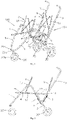
- a double stroller comprises a stroller frame having an unfolded state and a folded state, at least one front wheel assembly 20 disposed at a front portion of a bottom of the stroller frame, rear wheel assemblies 30 disposed at a rear portion of the bottom of the stroller frame, and a lock mechanism for locking the stroller frame in the unfolded state.
- the stroller frame comprises two side frames 100 provided at right and left sides respectively, and a transverse brace assembly connected between the side frames 100 on both sides.
- the side frame 100 of each side comprises a front support rod 1, a rear support rod 2, a push rod 3, a front seat rod 4 and a rear seat rod 5, wherein, the front support rod 1 gradually inclines upward from front to back, the rear support rod 2 aslant extends along an up-down direction, and an upper portion of the rear support rod 2 is pivotally connected with an upper portion of the front support rod 1 via a rotatory shaft 15; the push rod 3 aslant extends in the up-down direction and a lower portion thereof being pivotally connected to a sliding element 6, and the sliding element 6 is disposed on the rear support rod 2 in a manner so as to slide in the up-down direction, and here, the sliding element 6 employs a sliding sleeve 6 slidably sleeved on the rear support rod 2.
- the front seat rod 4 and the rear seat rod 5 respectively extend in a front-rear direction, a front portion of the front seat rod 4 is pivotally connected to the front support rod 1 via a first shaft 11, and a rear portion of the front seat rod 4 is pivotally connected with a front portion of the rear seat rod 5 via a second shaft 12; a middle portion of the rear seat rod 5 is pivotally connected to the rear support rod 2 via a third shaft 13, and a rear portion of the rear seat rod 5 is pivotally connected to the push rod 3 via a fourth shaft 14.
- the front seat rod 4 and the rear seat rod 5 extend along a same length direction, and the first shaft 11, the second shaft 12, the third shaft 13 and the fourth shaft 14 are sequentially distributed at intervals along the front-rear direction, wherein, a position where the first shaft 11 is on the front support rod 1 is below the rotatory shaft 15, a position where the sliding sleeve 6 is on the rear support rod 2 is disposed below the third shaft 13, and a position where the fourth shaft 14 is on the push rod 3 is located above the sliding sleeve 6.
- the stroller in the present embodiment is a three-wheel stroller
- the front wheel assembly 20 is disposed to be one set
- each front support rod 1 is an arc-shaped rod
- lower portions of the front support rods 1 on both sides are connected to form an U-shape with an opening upward
- the front wheel assembly 20 is connected with the lower portions of the front support rods 1 on both sides
- the two sets of rear wheel assemblies 30 are respectively disposed at bottoms of the rear support rods 2 on both sides.
- the stroller frame further comprises a front backrest assembly 8 disposed between rear portions of the front seat rods 4 on both sides, and a rear backrest assembly 9 disposed between rear portions of the rear seat rods 5 on both sides.
- the front backrest assembly 8 has two front backrest rods 81 respectively disposed at the left and right sides and both extending along the up-down direction, and a front connecting rod group connected between the two front backrest rods 81 on both sides, and a lower portion of the front backrest rod 81 is pivotally connected to the rear portion of the front seat rod 4 at the same side thereto;
- the rear backrest assembly 9 has two rear backrest rods 91 respectively disposed at the left and right sides and both extending along the up-down direction, and a rear connecting rod group connected between the two rear backrest rods 91 on both sides, and a lower portion of the rear backrest rod 91 is pivotally connected to the rear portion of the rear seat rod 5 at the same side thereto.
- the front backrest assembly 8 and the front seat rods 4 on both sides form a first seat that may provide a sitting position for one child to sit
- the rear backrest assembly 9 and the rear seat rods 5 on both sides form a second seat that may provide a sitting position for another child to sit.
- the stroller may provide two seats in tandem for two children to sit in the stroller when the stroller is unfolded.
- the lower portions of the front support rods 1 on both sides are rotatably connected, and a transverse brace assembly is disposed between the side frames 100 on both sides in a manner that it is foldable along the left-right direction. Specifically:
- the front wheel assembly comprises a front wheel frame 20a and front wheels 20b disposed at a bottom of the front wheel frame 20a, and lower portions of the front support rods 1 on both sides are respectively pivotally connected to the front wheel frame 20a, or lower portions of the front support rods 1 on both sides are rotatably connected to the front wheel frame 20a around a same center line of rotation.
- the lower portions of the front support rods 1 on both sides are pivotally connected to the front wheel frame 20a via a pin shaft 20c such that when the transverse brace assembly are folded along the left-right direction, the front support rods 1 on both sides are rotatable about the pin shaft 20c to get close to each other.
- the transverse brace assembly comprises a cross-shaped brace assembly 7 that comprises two inclined brace rods 71 intersecting with each other and pivotally connected at the intersection point, each of the inclined brace rods 71 aslant extends substantially along the up-down direction.
- An upper portion of each inclined brace rod 71 is rotatably connected to the rear support rod 2 on one side, and a lower portion thereof is rotatably connected to the sliding element 6 on the other side.
- the transverse brace assembly further comprises a rear attachment brace assembly 10 disposed between the push rods 3 on both sides and being unfoldable and foldable along the left-right direction.
- the rear attachment brace assembly 10 employs the attachment brace assemblies with a unfolding self-locking function that are frequently used in the art, and when being unfolded, may provide a stable support on the left-right direction for the push rods 3 on both sides.
- the rear attachment brace assembly 10 also may employ a structure that can achieve unfolding and folding in the left-right direction.
- the front connecting rod group of the front backrest assembly 8 and the rear connecting rod group of the rear backrest assembly 9 are both rod group structures that may get folded along the left-right direction.
- the stroller frame is locked in the unfolded state through the lock mechanism, and the rear attachment brace assembly 10 and the cross-shaped brace assembly 7 supports along the left-right direction between the side frames 100 on both sides.
- the front seat rod 4 and the rear seat rod 5 extend in the same length direction, and the front support rod 1, the rear support rod 2, the front seat rod 4 and the rear seat rod 5 form a stable triangular structure, and the push rod 3, the rear support rod 2 and the rear seat rod 5 form another stable triangular structure, which makes the stroller frame have a good rigidity and stability in the unfolded state.
- the front seat rod 4 and the rear seat rod 5 can be disposed in a large extension length in the front-rear direction, so that a large seating space for two children can be formed, so that in the double stroller each of the two seats provided for children to sit in tandem has a large space, thereby improving the comfort of seating for children.
- the lower portions of the inclined brace rods 71 of the cross-shaped brace assembly 7 move downward with the sliding sleeve 6 to bring the rear support rods 2 on both sides to get drawn together in the left-right direction, and the push rods 3 on both sides are drawn close gradually during the process the rear attachment brace assembly 10 get folded at the left-right direction, the front support rods 1 on both sides are rotated around the pin shaft 20c and gradually drawn close together in the left-right direction, so that the side frames 100 on both sides are gradually drawn close in the left-right direction, and the front backrest assembly 8 and the rear backrest assembly 9 are also folded between the side frames 100 on both sides during the above folding process, and the front wheel assembly 20 and the rear wheel assembly 30 are gradually drawn close together in the front-rear direction.
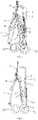
- the folded stroller frame is shown in Fig. 5 and Fig. 6 , the rods on the stroller frame are tightly gathered together, showing a very compact structure, which takes up less space, and the folded frame can rely on the front wheel assembly 20 and the rear wheel assembly 30 to stand on the ground for convenient daily storage and carrying.
- the operator stands behind the stroller, and the foot is stepped on the lower portion of the rear attachment brace assembly 10 such that the rear attachment brace assembly 10 is gradually unfolded in the left-right direction while the push rod 3 is lifted upwardly such that the sliding sleeve 6 is slid upward along the rear support 2, so that the rods on the stroller frame are rotated with respect to each other to gradually get unfolded.
- the unfolding operations of the double stroller are also convenient.
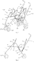
- Embodiment 1 the main difference from Embodiment 1 is the connection form of the front support rods 1 on both sides and the arrangement of the front wheel assembly 20.
- Fig. 7 to Fig. 12 there are two sets of front wheel assemblies 20, and the two sets of front wheel assemblies 20 are respectively disposed at the bottoms of the front support rods 1 on both sides.
- the lower portion of the front support rod 1 on each side has a connecting crossbar la extending inward in the left-right direction, and the connecting crossbars 1a on both sides are pivotally connected via a connecting shaft 16.
- the side frames 100 on both sides are respectively unfolded, and the cross-shaped brace assembly 7 of the transverse brace assembly and the rear attachment brace assembly 10 are spread between the side frames 100 on both sides, and the connecting crossbars 1a at the lower portions of the front support rods 1 on both sides are also unfolded in the left-right direction.
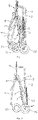
- the side frames 100 on both sides are respectively folded, and the cross-shaped brace assembly 7 of the transverse brace assembly and the rear attachment brace assembly 10 are also respectively folded along the left-right direction, so that the side frames 100 on both sides are gradually drawn close in the left-right direction, and the front support rods 1 on both sides are rotated about the connecting shaft 16 and gradually drawn close in the left-right direction.
- the folded frame is as shown in Fig. 11 and Fig. 12 , and the folded frame is compact in structure and can rely on two sets of front wheel assemblies 20 and two sets of rear wheel assemblies 30 to stand on the ground.
- the stroller has few rod pieces and a simple structure, has a good rigidity in an unfolded state, and may set two seats in tandem to provide supports for two children to sit stably, and has a large space for the children sitting in the stroller frame with a high sitting comfortability.
- the unfolding and folding operations of the double stroller are also convenient, and the volume thereof after folding is small, which provides convenience for daily storage and carrying of the user.
- the above words of locality such as up, down, front, rear, left, and right, are defined in a state in which the stroller frame is in an unfolded state, and the position where the front wheel assembly 20 is front, and the position where the rear wheel assembly 30 is rear.
Landscapes
- Engineering & Computer Science (AREA)
- Chemical & Material Sciences (AREA)
- Combustion & Propulsion (AREA)
- Transportation (AREA)
- Mechanical Engineering (AREA)
- Health & Medical Sciences (AREA)
- Child & Adolescent Psychology (AREA)
- General Health & Medical Sciences (AREA)
- Carriages For Children, Sleds, And Other Hand-Operated Vehicles (AREA)
Claims (11)
- Doppel-Kinderwagen mit einem Kinderwagenrahmen mit einem aufgeklappten Zustand und einem zusammengeklappten Zustand, mindestens einer Vorderradanordnung (20), die an einem vorderen Abschnitt einer Unterseite des Kinderwagenrahmens angeordnet ist, zwei Hinterradanordnungen (30), die an einem hinteren Abschnitt der Unterseite des Kinderwagenrahmens angeordnet sind, und einem Verriegelungsmechanismus zum Verriegeln des Kinderwagenrahmens im aufgeklappten Zustand, wobei der Kinderwagenrahmen zwei Seitenrahmen (100) umfasst, die jeweils auf der rechten und linken Seite vorgesehen sind, und einer Querstrebenanordnung, die zwischen den Seitenrahmen (100) auf beiden Seiten eingebunden ist, wobei der Seitenrahmen (100) jeder Seite eine vordere Stützstange (1) umfasst, die sich allmählich von vorne nach hinten nach oben neigt, eine hintere Stützstange (2), die sich entlang einer Oben-Unten-Richtung erstreckt, ein Gleitelement (6), das verschiebbar an der hinteren Stützstange (2) so angeordnet ist, dass es in der Oben-Unten-Richtung gleitet, und eine Schubstange (3), die sich in einer Oben-Unten-Richtung erstreckt, wobei ein unterer Abschnitt schwenkbar mit dem Gleitelement (6) verbunden ist, dadurch gekennzeichnet, dass der Seitenrahmen (100) jeder Seite ferner eine vordere Sitzstange (4) und eine hintere Sitzstange umfasst (5), die sich jeweils in einer Vorne-Hinten-Richtung erstrecken, wobei ein vorderer Abschnitt der vorderen Sitzstange (4) schwenkbar mit der vorderen Stützstange (1) verbunden ist, die hintere Sitzstange (5) schwenkbar mit der hinteren Stützstange verbunden ist (2), ein vorderer Abschnitt der hinteren Sitzstange (5) schwenkbar mit einem hinteren Abschnitt der vorderen Sitzstange (4) verbunden ist und ein hinterer Abschnitt der hinteren Sitzstange (5) schwenkbar mit der Schubstange (3) verbunden ist, und untere Abschnitte der vorderen Stützstangen (1) auf beiden Seiten drehbar miteinander verbunden sind, und die Querstrebenanordnung zwischen den Seitenrahmen (100) auf beiden Seiten angeordnet ist und entlang einer Links-Rechts-Richtung gefaltet werden kann, wobei
beim Zusammenklappen des Kinderwagengestells die vordere Sitzstange (4) und die hintere Sitzstange (5) des Seitenrahmens (100) jeder Seite entlang der Vorne-Hinten-Richtung gedreht und gefaltet wird und das Gleitelement (6) nach unten entlang der hinteren Stützstange (2) gleitet, so dass die vordere Stützstange (1), die hintere Stützstange (2), die vordere Sitzstange (4), die hintere Sitzstange (5) und die Schubstange (3) entlang der Vorne-Hinten-Richtung nahe zueinander gezogen werden, um das Falten des Seitenrahmens (100) zu erreichen, wobei die Querstrebenanordnung so gefaltet wird, dass die Seitenrahmen (100) auf beiden Seiten entlang der Links-Rechts-Richtung nahe zueinander gezogen werden, und die Vorderradanordnung (20) und die Hinterradanordnung (30) entlang der Vorne-Hinten-Richtung nahe zueinander gezogen werden. - Doppelkinderwagen nach Anspruch 1, dadurch gekennzeichnet, dass, wenn sich das Kinderwagengestell im aufgeklappten Zustand befindet, die vordere Sitzstange (4) und die hintere Sitzstange (5) sich entlang einer gleichen Längenrichtung erstrecken.
- Doppelkinderwagen nach Anspruch 1, dadurch gekennzeichnet, dass beim Zusammenklappen des Kinderwagengestells am Seitenrahmen (100) jeder Seite ein hinterer Endabschnitt der Vordersitzstange (4) und ein vorderer Endabschnitt der Hinteren Sitzstange (5) sich zusammen nach oben bewegen, so dass die vordere Sitzstange (4) und die hintere Sitzstange (5) relativ zueinander entlang der Vorne-Hinten-Richtung gedreht und allmählich nahe zueinander gezogen werden.
- Doppelkinderwagen nach Anspruch 1, dadurch gekennzeichnet, dass der vordere Abschnitt der vorderen Sitzstange (4) schwenkbar mit der vorderen Stützstange (1) über eine erste Welle (11) verbunden ist, der hintere Abschnitt der vorderen Sitzstange (4) schwenkbar über eine zweite Welle (12) mit dem vorderen Abschnitt der hinteren Sitzstange (5) verbunden ist, wobei die hintere Sitzstange (5) schwenkbar mit der hinteren Stützstange über eine dritte Welle (13) verbunden ist und der hintere Abschnitt der hinteren Sitzstange (5) schwenkbar mit der Schubstange (3) über eine vierte Welle (14) verbunden ist, und wenn das Kinderwagengestell aufgeklappt ist, die erste Welle (11), die zweite Welle (12), die dritte Welle (13) und die vierte Welle (14) nacheinander in Abständen entlang der Vorne-Hinten-Richtung verteilt sind.
- Doppelkinderwagen nach Anspruch 4, dadurch gekennzeichnet, dass das Gleitelement (6) eine Gleithülse ist, die verschiebbar auf der hinteren Stützstange (2) angeordnet ist, wobei eine Position, wo die Gleithülse auf der hinteren Stützstange ist, unterhalb der dritten Welle (13) angeordnet ist, und eine Position, wo die vierte Welle angeordnet ist (14) sich auf der Schubstange (3) oberhalb der Gleithülse befindet.
- Doppelkinderwagen nach Anspruch 1, dadurch gekennzeichnet, dass untere Abschnitte der vorderen Stützstangen (1) auf beiden Seiten verbunden sind, um eine U-Form mit einer Öffnung nach oben zu bilden, und es einen Vorderradanordnungssatz (20) gibt und die Vorderradanordnung (20) mit den unteren Abschnitten der vorderen Stützstangen (1) auf beiden Seiten verbunden ist; wobei es zwei Sätze von Hinterradanordnungen (30) gibt, die jeweils an Unterteilen der hinteren Stützstangen (2) auf beiden Seiten angeordnet sind.
- Doppelkinderwagen nach Anspruch 1, dadurch gekennzeichnet, dass der Kinderwagenrahmen ferner eine vordere Rückenlehnenanordnung (8), die zwischen hinteren Abschnitten der vorderen Sitzstangen (4) auf beiden Seiten angeordnet ist, und eine hintere Rückenlehnenanordnung (9) umfasst, die zwischen hinteren Abschnitten der hinteren Sitzstangen (5) auf beiden Seiten angeordnet ist, wobei die vordere Rückenlehnenanordnung (8) und die vorderen Sitzstangen (4) auf beiden Seiten einen ersten Sitz bilden, und die hintere Rückenlehnenanordnung (9) und die hinteren Sitzstangen (5) auf beiden Seiten einen zweiten Sitz bilden.
- Doppelkinderwagen nach einem der Ansprüche 1 bis 7, dadurch gekennzeichnet, dass die Querstrebe mindestens eine kreuzförmige Strebe (7) umfasst, die zwei sich kreuzende und im Kreuzungspunkt schwenkbar verbundene geneigte Strebenstangen (71) umfasst, wobei sich jede der geneigten Strebenstangen (71) entlang einer Oben-Unten-Richtung erstreckt, ein oberer Abschnitt jeder geneigten Strebenstange (71) drehbar mit der hinteren Stützstange (2) auf einer Seite verbunden ist und ein unterer Abschnitt davon drehbar mit dem Gleitelement (6) verbunden ist.
- Doppelkinderwagen nach Anspruch 8, dadurch gekennzeichnet, die Querstrebenanordnung ferner eine hintere Befestigungsstrebenanordnung (10) umfasst, die zwischen den Schubstangen (3) auf beiden Seiten angeordnet ist und entlang der Links-Rechts-Richtung entfaltbar und faltbar ist.
- Doppelkinderwagen nach Anspruch 1, dadurch gekennzeichnet, dass die Vorderradanordnung (20) einen Vorderradrahmen (20a) und Vorderräder (20b) umfasst, die an einer Unterseite des Vorderradrahmens (20a) angeordnet sind, und untere Abschnitte der vorderen Stützstangen (1) auf beiden Seiten jeweils schwenkbar mit dem Vorderradrahmen (20a) verbunden sind, oder untere Abschnitte der vorderen Stützstangen (1) auf beiden Seiten um eine gleiche Rotationsmittellinie drehbar mit dem Vorderradrahmen (20a) verbunden sind.
- Doppel-Kinderwagen nach Anspruch 1, dadurch gekennzeichnet, dass zwei Sätze von Vorderradanordnungen (20) jeweils an Unterteilen der vorderen Stützstangen (1) auf beiden Seiten angeordnet sind, und die unteren Abschnitten der vorderen Stützstangen (1) auf beiden Seiten schwenkbar verbunden sind.
Applications Claiming Priority (2)
| Application Number | Priority Date | Filing Date | Title |
|---|---|---|---|
| CN201611113538.9A CN107042839A (zh) | 2016-12-06 | 2016-12-06 | 双人儿童推车 |
| PCT/CN2016/111257 WO2018103140A1 (zh) | 2016-12-06 | 2016-12-21 | 双人儿童推车 |
Publications (3)
| Publication Number | Publication Date |
|---|---|
| EP3552922A1 EP3552922A1 (de) | 2019-10-16 |
| EP3552922A4 EP3552922A4 (de) | 2020-08-12 |
| EP3552922B1 true EP3552922B1 (de) | 2022-08-17 |
Family
ID=59542824
Family Applications (1)
| Application Number | Title | Priority Date | Filing Date |
|---|---|---|---|
| EP16923568.6A Not-in-force EP3552922B1 (de) | 2016-12-06 | 2016-12-21 | Zwei-personen-kinderwagen |
Country Status (3)
| Country | Link |
|---|---|
| EP (1) | EP3552922B1 (de) |
| CN (1) | CN107042839A (de) |
| WO (1) | WO2018103140A1 (de) |
Families Citing this family (7)
| Publication number | Priority date | Publication date | Assignee | Title |
|---|---|---|---|---|
| CN108177679B (zh) * | 2018-01-09 | 2023-12-29 | 好孩子儿童用品有限公司 | 儿童推车 |
| TWI728356B (zh) * | 2018-07-05 | 2021-05-21 | 穩正企業股份有限公司 | 移動載具及其收折方法 |
| CN110001736B (zh) * | 2019-04-02 | 2023-11-24 | 好孩子儿童用品有限公司 | 儿童推车 |
| CN112009556B (zh) * | 2020-08-04 | 2024-11-29 | 好孩子儿童用品有限公司 | 婴儿提篮及具有该婴儿提篮的童车 |
| CN112009547B (zh) * | 2020-08-18 | 2024-11-29 | 好孩子儿童用品有限公司 | 双人儿童推车 |
| CN112278057B (zh) * | 2020-10-10 | 2024-11-29 | 好孩子儿童用品有限公司 | 儿童推车 |
| CN115817620B (zh) * | 2022-11-28 | 2024-11-01 | 好孩子儿童用品有限公司 | 儿童推车及其靠背组件 |
Family Cites Families (21)
| Publication number | Priority date | Publication date | Assignee | Title |
|---|---|---|---|---|
| US4706986A (en) * | 1985-07-31 | 1987-11-17 | Aprica Kassai Kabushikikaisha | Mechanism for locking opened state of baby carriage |
| JPH09263246A (ja) * | 1996-03-29 | 1997-10-07 | Combi Corp | 折り畳み構造を有する着座装置 |
| US6267406B1 (en) * | 2000-08-08 | 2001-07-31 | Mien Chen Huang | Structure of folding-collapsible double-seat baby stroller |
| US20030020259A1 (en) * | 2001-07-27 | 2003-01-30 | Chuan-Tso Tai | Collapsible dual-seat jogging stroller with side rails |
| US8066300B2 (en) * | 2007-10-22 | 2011-11-29 | Aprica Children's Products Inc. | Foldable pushcart and foldable baby carriage |
| JP5232437B2 (ja) * | 2007-10-22 | 2013-07-10 | アップリカ・チルドレンズプロダクツ株式会社 | 幌付折畳式乳母車 |
| CN102303548B (zh) * | 2008-10-01 | 2014-10-01 | 明门实业股份有限公司 | 婴儿车及婴儿车与汽车座椅的组合 |
| CN101879910B (zh) * | 2009-05-05 | 2012-10-24 | 明门实业股份有限公司 | 双人座的婴儿车架 |
| CN101987630B (zh) * | 2009-07-29 | 2013-01-09 | 明门香港股份有限公司 | 双人座婴儿车架 |
| CN201784657U (zh) * | 2010-07-02 | 2011-04-06 | 好孩子儿童用品有限公司 | 儿童推车 |
| CN102343925B (zh) * | 2010-08-02 | 2013-04-03 | 明门香港股份有限公司 | 可收合婴儿车车架 |
| GB2502873B (en) * | 2012-04-10 | 2018-11-07 | Wonderland Switzerland Ag | Tandem stroller with detachable height-adjustable rear seat |
| CA2820907C (en) * | 2012-07-10 | 2020-10-20 | Toshihiro Kikui | Stroller |
| CN102862597B (zh) * | 2012-09-25 | 2015-10-21 | 好孩子儿童用品有限公司 | 儿童推车 |
| FR3016595A1 (fr) * | 2014-01-22 | 2015-07-24 | Pao Hsien Cheng | Structure pliable pour empecher le dossier d'une poussette d'etre incline vers l'avant. |
| CN104192190B (zh) * | 2014-08-21 | 2017-04-05 | 好孩子儿童用品有限公司 | 双向折叠推车 |
| CN104554410B (zh) * | 2014-12-26 | 2017-01-04 | 好孩子儿童用品有限公司 | 一种可二次折叠的双人推车 |
| CN204623530U (zh) * | 2015-04-08 | 2015-09-09 | 好孩子儿童用品有限公司 | 儿童推车 |
| CN205344999U (zh) * | 2015-12-16 | 2016-06-29 | 好孩子儿童用品有限公司 | 儿童推车 |
| CN205524413U (zh) * | 2016-01-20 | 2016-08-31 | 好孩子儿童用品有限公司 | 一种双人推车 |
| CN206384009U (zh) * | 2016-12-06 | 2017-08-08 | 好孩子儿童用品有限公司 | 双人儿童推车 |
-
2016
- 2016-12-06 CN CN201611113538.9A patent/CN107042839A/zh active Pending
- 2016-12-21 EP EP16923568.6A patent/EP3552922B1/de not_active Not-in-force
- 2016-12-21 WO PCT/CN2016/111257 patent/WO2018103140A1/zh not_active Ceased
Also Published As
| Publication number | Publication date |
|---|---|
| CN107042839A (zh) | 2017-08-15 |
| WO2018103140A1 (zh) | 2018-06-14 |
| EP3552922A4 (de) | 2020-08-12 |
| EP3552922A1 (de) | 2019-10-16 |
Similar Documents
| Publication | Publication Date | Title |
|---|---|---|
| EP3552922B1 (de) | Zwei-personen-kinderwagen | |
| US11904925B2 (en) | Folding stroller | |
| EP3552923B1 (de) | Zusammenklappbares kinderwagengestell und zusammenklappbarer kinderwagen | |
| CN111907578A (zh) | 多人座婴幼儿推车 | |
| CN206384014U (zh) | 儿童座兜及儿童推车 | |
| CN206968734U (zh) | 一种双人儿童推车 | |
| CN110481621A (zh) | 儿童推车 | |
| CN213831850U (zh) | 儿童推车 | |
| CN114104070A (zh) | 双人儿童推车 | |
| CN206465986U (zh) | 一种双向婴儿折叠推车 | |
| CN104192190A (zh) | 双向折叠推车 | |
| CN109606452B (zh) | 一种儿童推车 | |
| CN207790800U (zh) | 一种婴儿车 | |
| CN108177679B (zh) | 儿童推车 | |
| CN205469214U (zh) | 可折叠婴儿车 | |
| CN104290793A (zh) | 一种双向折叠儿童推车 | |
| CN221068181U (zh) | 推车 | |
| CN204055901U (zh) | 双向折叠推车 | |
| CN206968735U (zh) | 一种双人儿童推车 | |
| CN206317872U (zh) | 儿童推车 | |
| CN112407013B (zh) | 儿童推车 | |
| CN205273573U (zh) | 一种童车骨架 | |
| CN206384009U (zh) | 双人儿童推车 | |
| CN211494194U (zh) | 一种可折叠推车车架 | |
| CN109278838B (zh) | 儿童推车 |
Legal Events
| Date | Code | Title | Description |
|---|---|---|---|
| STAA | Information on the status of an ep patent application or granted ep patent |
Free format text: STATUS: THE INTERNATIONAL PUBLICATION HAS BEEN MADE |
|
| PUAI | Public reference made under article 153(3) epc to a published international application that has entered the european phase |
Free format text: ORIGINAL CODE: 0009012 |
|
| STAA | Information on the status of an ep patent application or granted ep patent |
Free format text: STATUS: REQUEST FOR EXAMINATION WAS MADE |
|
| 17P | Request for examination filed |
Effective date: 20190625 |
|
| AK | Designated contracting states |
Kind code of ref document: A1 Designated state(s): AL AT BE BG CH CY CZ DE DK EE ES FI FR GB GR HR HU IE IS IT LI LT LU LV MC MK MT NL NO PL PT RO RS SE SI SK SM TR |
|
| AX | Request for extension of the european patent |
Extension state: BA ME |
|
| DAV | Request for validation of the european patent (deleted) | ||
| DAX | Request for extension of the european patent (deleted) | ||
| A4 | Supplementary search report drawn up and despatched |
Effective date: 20200713 |
|
| RIC1 | Information provided on ipc code assigned before grant |
Ipc: B62B 7/00 20060101ALI20200707BHEP Ipc: B62B 7/08 20060101AFI20200707BHEP |
|
| STAA | Information on the status of an ep patent application or granted ep patent |
Free format text: STATUS: EXAMINATION IS IN PROGRESS |
|
| 17Q | First examination report despatched |
Effective date: 20210623 |
|
| GRAP | Despatch of communication of intention to grant a patent |
Free format text: ORIGINAL CODE: EPIDOSNIGR1 |
|
| STAA | Information on the status of an ep patent application or granted ep patent |
Free format text: STATUS: GRANT OF PATENT IS INTENDED |
|
| INTG | Intention to grant announced |
Effective date: 20220316 |
|
| GRAS | Grant fee paid |
Free format text: ORIGINAL CODE: EPIDOSNIGR3 |
|
| GRAA | (expected) grant |
Free format text: ORIGINAL CODE: 0009210 |
|
| STAA | Information on the status of an ep patent application or granted ep patent |
Free format text: STATUS: THE PATENT HAS BEEN GRANTED |
|
| AK | Designated contracting states |
Kind code of ref document: B1 Designated state(s): AL AT BE BG CH CY CZ DE DK EE ES FI FR GB GR HR HU IE IS IT LI LT LU LV MC MK MT NL NO PL PT RO RS SE SI SK SM TR |
|
| REG | Reference to a national code |
Ref country code: CH Ref legal event code: EP |
|
| REG | Reference to a national code |
Ref country code: DE Ref legal event code: R096 Ref document number: 602016074423 Country of ref document: DE |
|
| REG | Reference to a national code |
Ref country code: IE Ref legal event code: FG4D |
|
| REG | Reference to a national code |
Ref country code: AT Ref legal event code: REF Ref document number: 1511993 Country of ref document: AT Kind code of ref document: T Effective date: 20220915 |
|
| REG | Reference to a national code |
Ref country code: NL Ref legal event code: FP |
|
| REG | Reference to a national code |
Ref country code: LT Ref legal event code: MG9D |
|
| PG25 | Lapsed in a contracting state [announced via postgrant information from national office to epo] |
Ref country code: SE Free format text: LAPSE BECAUSE OF FAILURE TO SUBMIT A TRANSLATION OF THE DESCRIPTION OR TO PAY THE FEE WITHIN THE PRESCRIBED TIME-LIMIT Effective date: 20220817 Ref country code: RS Free format text: LAPSE BECAUSE OF FAILURE TO SUBMIT A TRANSLATION OF THE DESCRIPTION OR TO PAY THE FEE WITHIN THE PRESCRIBED TIME-LIMIT Effective date: 20220817 Ref country code: PT Free format text: LAPSE BECAUSE OF FAILURE TO SUBMIT A TRANSLATION OF THE DESCRIPTION OR TO PAY THE FEE WITHIN THE PRESCRIBED TIME-LIMIT Effective date: 20221219 Ref country code: NO Free format text: LAPSE BECAUSE OF FAILURE TO SUBMIT A TRANSLATION OF THE DESCRIPTION OR TO PAY THE FEE WITHIN THE PRESCRIBED TIME-LIMIT Effective date: 20221117 Ref country code: LV Free format text: LAPSE BECAUSE OF FAILURE TO SUBMIT A TRANSLATION OF THE DESCRIPTION OR TO PAY THE FEE WITHIN THE PRESCRIBED TIME-LIMIT Effective date: 20220817 Ref country code: LT Free format text: LAPSE BECAUSE OF FAILURE TO SUBMIT A TRANSLATION OF THE DESCRIPTION OR TO PAY THE FEE WITHIN THE PRESCRIBED TIME-LIMIT Effective date: 20220817 Ref country code: FI Free format text: LAPSE BECAUSE OF FAILURE TO SUBMIT A TRANSLATION OF THE DESCRIPTION OR TO PAY THE FEE WITHIN THE PRESCRIBED TIME-LIMIT Effective date: 20220817 |
|
| PGFP | Annual fee paid to national office [announced via postgrant information from national office to epo] |
Ref country code: NL Payment date: 20221222 Year of fee payment: 7 Ref country code: GB Payment date: 20221223 Year of fee payment: 7 Ref country code: FR Payment date: 20221222 Year of fee payment: 7 Ref country code: DE Payment date: 20221213 Year of fee payment: 7 |
|
| REG | Reference to a national code |
Ref country code: AT Ref legal event code: MK05 Ref document number: 1511993 Country of ref document: AT Kind code of ref document: T Effective date: 20220817 |
|
| PG25 | Lapsed in a contracting state [announced via postgrant information from national office to epo] |
Ref country code: PL Free format text: LAPSE BECAUSE OF FAILURE TO SUBMIT A TRANSLATION OF THE DESCRIPTION OR TO PAY THE FEE WITHIN THE PRESCRIBED TIME-LIMIT Effective date: 20220817 Ref country code: IS Free format text: LAPSE BECAUSE OF FAILURE TO SUBMIT A TRANSLATION OF THE DESCRIPTION OR TO PAY THE FEE WITHIN THE PRESCRIBED TIME-LIMIT Effective date: 20221217 Ref country code: HR Free format text: LAPSE BECAUSE OF FAILURE TO SUBMIT A TRANSLATION OF THE DESCRIPTION OR TO PAY THE FEE WITHIN THE PRESCRIBED TIME-LIMIT Effective date: 20220817 Ref country code: GR Free format text: LAPSE BECAUSE OF FAILURE TO SUBMIT A TRANSLATION OF THE DESCRIPTION OR TO PAY THE FEE WITHIN THE PRESCRIBED TIME-LIMIT Effective date: 20221118 |
|
| PG25 | Lapsed in a contracting state [announced via postgrant information from national office to epo] |
Ref country code: SM Free format text: LAPSE BECAUSE OF FAILURE TO SUBMIT A TRANSLATION OF THE DESCRIPTION OR TO PAY THE FEE WITHIN THE PRESCRIBED TIME-LIMIT Effective date: 20220817 Ref country code: RO Free format text: LAPSE BECAUSE OF FAILURE TO SUBMIT A TRANSLATION OF THE DESCRIPTION OR TO PAY THE FEE WITHIN THE PRESCRIBED TIME-LIMIT Effective date: 20220817 Ref country code: ES Free format text: LAPSE BECAUSE OF FAILURE TO SUBMIT A TRANSLATION OF THE DESCRIPTION OR TO PAY THE FEE WITHIN THE PRESCRIBED TIME-LIMIT Effective date: 20220817 Ref country code: DK Free format text: LAPSE BECAUSE OF FAILURE TO SUBMIT A TRANSLATION OF THE DESCRIPTION OR TO PAY THE FEE WITHIN THE PRESCRIBED TIME-LIMIT Effective date: 20220817 Ref country code: CZ Free format text: LAPSE BECAUSE OF FAILURE TO SUBMIT A TRANSLATION OF THE DESCRIPTION OR TO PAY THE FEE WITHIN THE PRESCRIBED TIME-LIMIT Effective date: 20220817 Ref country code: AT Free format text: LAPSE BECAUSE OF FAILURE TO SUBMIT A TRANSLATION OF THE DESCRIPTION OR TO PAY THE FEE WITHIN THE PRESCRIBED TIME-LIMIT Effective date: 20220817 |
|
| REG | Reference to a national code |
Ref country code: DE Ref legal event code: R097 Ref document number: 602016074423 Country of ref document: DE |
|
| PG25 | Lapsed in a contracting state [announced via postgrant information from national office to epo] |
Ref country code: SK Free format text: LAPSE BECAUSE OF FAILURE TO SUBMIT A TRANSLATION OF THE DESCRIPTION OR TO PAY THE FEE WITHIN THE PRESCRIBED TIME-LIMIT Effective date: 20220817 Ref country code: EE Free format text: LAPSE BECAUSE OF FAILURE TO SUBMIT A TRANSLATION OF THE DESCRIPTION OR TO PAY THE FEE WITHIN THE PRESCRIBED TIME-LIMIT Effective date: 20220817 |
|
| PLBE | No opposition filed within time limit |
Free format text: ORIGINAL CODE: 0009261 |
|
| STAA | Information on the status of an ep patent application or granted ep patent |
Free format text: STATUS: NO OPPOSITION FILED WITHIN TIME LIMIT |
|
| PG25 | Lapsed in a contracting state [announced via postgrant information from national office to epo] |
Ref country code: AL Free format text: LAPSE BECAUSE OF FAILURE TO SUBMIT A TRANSLATION OF THE DESCRIPTION OR TO PAY THE FEE WITHIN THE PRESCRIBED TIME-LIMIT Effective date: 20220817 |
|
| 26N | No opposition filed |
Effective date: 20230519 |
|
| REG | Reference to a national code |
Ref country code: CH Ref legal event code: PL |
|
| REG | Reference to a national code |
Ref country code: BE Ref legal event code: MM Effective date: 20221231 |
|
| PG25 | Lapsed in a contracting state [announced via postgrant information from national office to epo] |
Ref country code: SI Free format text: LAPSE BECAUSE OF FAILURE TO SUBMIT A TRANSLATION OF THE DESCRIPTION OR TO PAY THE FEE WITHIN THE PRESCRIBED TIME-LIMIT Effective date: 20220817 Ref country code: LU Free format text: LAPSE BECAUSE OF NON-PAYMENT OF DUE FEES Effective date: 20221221 |
|
| PG25 | Lapsed in a contracting state [announced via postgrant information from national office to epo] |
Ref country code: LI Free format text: LAPSE BECAUSE OF NON-PAYMENT OF DUE FEES Effective date: 20221231 Ref country code: IE Free format text: LAPSE BECAUSE OF NON-PAYMENT OF DUE FEES Effective date: 20221221 Ref country code: CH Free format text: LAPSE BECAUSE OF NON-PAYMENT OF DUE FEES Effective date: 20221231 |
|
| PG25 | Lapsed in a contracting state [announced via postgrant information from national office to epo] |
Ref country code: BE Free format text: LAPSE BECAUSE OF NON-PAYMENT OF DUE FEES Effective date: 20221231 |
|
| PG25 | Lapsed in a contracting state [announced via postgrant information from national office to epo] |
Ref country code: HU Free format text: LAPSE BECAUSE OF FAILURE TO SUBMIT A TRANSLATION OF THE DESCRIPTION OR TO PAY THE FEE WITHIN THE PRESCRIBED TIME-LIMIT; INVALID AB INITIO Effective date: 20161221 |
|
| PG25 | Lapsed in a contracting state [announced via postgrant information from national office to epo] |
Ref country code: CY Free format text: LAPSE BECAUSE OF FAILURE TO SUBMIT A TRANSLATION OF THE DESCRIPTION OR TO PAY THE FEE WITHIN THE PRESCRIBED TIME-LIMIT Effective date: 20220817 |
|
| PG25 | Lapsed in a contracting state [announced via postgrant information from national office to epo] |
Ref country code: MK Free format text: LAPSE BECAUSE OF FAILURE TO SUBMIT A TRANSLATION OF THE DESCRIPTION OR TO PAY THE FEE WITHIN THE PRESCRIBED TIME-LIMIT Effective date: 20220817 Ref country code: IT Free format text: LAPSE BECAUSE OF FAILURE TO SUBMIT A TRANSLATION OF THE DESCRIPTION OR TO PAY THE FEE WITHIN THE PRESCRIBED TIME-LIMIT Effective date: 20220817 |
|
| PG25 | Lapsed in a contracting state [announced via postgrant information from national office to epo] |
Ref country code: MC Free format text: LAPSE BECAUSE OF FAILURE TO SUBMIT A TRANSLATION OF THE DESCRIPTION OR TO PAY THE FEE WITHIN THE PRESCRIBED TIME-LIMIT Effective date: 20220817 |
|
| PG25 | Lapsed in a contracting state [announced via postgrant information from national office to epo] |
Ref country code: MC Free format text: LAPSE BECAUSE OF FAILURE TO SUBMIT A TRANSLATION OF THE DESCRIPTION OR TO PAY THE FEE WITHIN THE PRESCRIBED TIME-LIMIT Effective date: 20220817 |
|
| REG | Reference to a national code |
Ref country code: DE Ref legal event code: R119 Ref document number: 602016074423 Country of ref document: DE |
|
| PG25 | Lapsed in a contracting state [announced via postgrant information from national office to epo] |
Ref country code: BG Free format text: LAPSE BECAUSE OF FAILURE TO SUBMIT A TRANSLATION OF THE DESCRIPTION OR TO PAY THE FEE WITHIN THE PRESCRIBED TIME-LIMIT Effective date: 20220817 |
|
| REG | Reference to a national code |
Ref country code: NL Ref legal event code: MM Effective date: 20240101 |
|
| GBPC | Gb: european patent ceased through non-payment of renewal fee |
Effective date: 20231221 |
|
| PG25 | Lapsed in a contracting state [announced via postgrant information from national office to epo] |
Ref country code: NL Free format text: LAPSE BECAUSE OF NON-PAYMENT OF DUE FEES Effective date: 20240101 |
|
| PG25 | Lapsed in a contracting state [announced via postgrant information from national office to epo] |
Ref country code: NL Free format text: LAPSE BECAUSE OF NON-PAYMENT OF DUE FEES Effective date: 20240101 Ref country code: MT Free format text: LAPSE BECAUSE OF FAILURE TO SUBMIT A TRANSLATION OF THE DESCRIPTION OR TO PAY THE FEE WITHIN THE PRESCRIBED TIME-LIMIT Effective date: 20220817 |
|
| PG25 | Lapsed in a contracting state [announced via postgrant information from national office to epo] |
Ref country code: DE Free format text: LAPSE BECAUSE OF NON-PAYMENT OF DUE FEES Effective date: 20240702 |
|
| PG25 | Lapsed in a contracting state [announced via postgrant information from national office to epo] |
Ref country code: GB Free format text: LAPSE BECAUSE OF NON-PAYMENT OF DUE FEES Effective date: 20231221 |
|
| PG25 | Lapsed in a contracting state [announced via postgrant information from national office to epo] |
Ref country code: FR Free format text: LAPSE BECAUSE OF NON-PAYMENT OF DUE FEES Effective date: 20231231 |
|
| PG25 | Lapsed in a contracting state [announced via postgrant information from national office to epo] |
Ref country code: GB Free format text: LAPSE BECAUSE OF NON-PAYMENT OF DUE FEES Effective date: 20231221 Ref country code: FR Free format text: LAPSE BECAUSE OF NON-PAYMENT OF DUE FEES Effective date: 20231231 Ref country code: DE Free format text: LAPSE BECAUSE OF NON-PAYMENT OF DUE FEES Effective date: 20240702 |
|
| PG25 | Lapsed in a contracting state [announced via postgrant information from national office to epo] |
Ref country code: TR Free format text: LAPSE BECAUSE OF FAILURE TO SUBMIT A TRANSLATION OF THE DESCRIPTION OR TO PAY THE FEE WITHIN THE PRESCRIBED TIME-LIMIT Effective date: 20220817 |