EP2869080B1 - Method of controling a terminal device and program - Google Patents
Method of controling a terminal device and program Download PDFInfo
- Publication number
- EP2869080B1 EP2869080B1 EP14190863.2A EP14190863A EP2869080B1 EP 2869080 B1 EP2869080 B1 EP 2869080B1 EP 14190863 A EP14190863 A EP 14190863A EP 2869080 B1 EP2869080 B1 EP 2869080B1
- Authority
- EP
- European Patent Office
- Prior art keywords
- terminal device
- sound wave
- electric wave
- user
- transmitter
- Prior art date
- Legal status (The legal status is an assumption and is not a legal conclusion. Google has not performed a legal analysis and makes no representation as to the accuracy of the status listed.)
- Active
Links
- 238000000034 method Methods 0.000 title claims description 26
- 238000012545 processing Methods 0.000 claims description 136
- 238000004891 communication Methods 0.000 claims description 56
- 230000005540 biological transmission Effects 0.000 claims description 34
- 230000004913 activation Effects 0.000 claims description 23
- 230000001133 acceleration Effects 0.000 claims description 3
- 230000003213 activating effect Effects 0.000 claims description 3
- 230000003287 optical effect Effects 0.000 description 47
- 238000001514 detection method Methods 0.000 description 38
- 238000010586 diagram Methods 0.000 description 24
- 230000005236 sound signal Effects 0.000 description 16
- 238000003384 imaging method Methods 0.000 description 15
- 230000006870 function Effects 0.000 description 10
- 230000008859 change Effects 0.000 description 9
- 230000010365 information processing Effects 0.000 description 5
- 230000000704 physical effect Effects 0.000 description 5
- 238000013459 approach Methods 0.000 description 4
- 230000000149 penetrating effect Effects 0.000 description 4
- 238000006243 chemical reaction Methods 0.000 description 3
- 239000000470 constituent Substances 0.000 description 3
- 238000005192 partition Methods 0.000 description 3
- 238000005070 sampling Methods 0.000 description 3
- 239000000284 extract Substances 0.000 description 2
- 238000009434 installation Methods 0.000 description 2
- 238000012986 modification Methods 0.000 description 2
- 230000004048 modification Effects 0.000 description 2
- 230000008569 process Effects 0.000 description 2
- 230000004397 blinking Effects 0.000 description 1
- 230000001413 cellular effect Effects 0.000 description 1
- 238000001914 filtration Methods 0.000 description 1
- 239000007788 liquid Substances 0.000 description 1
- 230000007257 malfunction Effects 0.000 description 1
- 230000004044 response Effects 0.000 description 1
- 239000004065 semiconductor Substances 0.000 description 1
- 239000007787 solid Substances 0.000 description 1
- 238000001228 spectrum Methods 0.000 description 1
- 238000012546 transfer Methods 0.000 description 1
Images


Classifications
-
- H—ELECTRICITY
- H04—ELECTRIC COMMUNICATION TECHNIQUE
- H04W—WIRELESS COMMUNICATION NETWORKS
- H04W4/00—Services specially adapted for wireless communication networks; Facilities therefor
- H04W4/02—Services making use of location information
- H04W4/029—Location-based management or tracking services
-
- G—PHYSICS
- G01—MEASURING; TESTING
- G01S—RADIO DIRECTION-FINDING; RADIO NAVIGATION; DETERMINING DISTANCE OR VELOCITY BY USE OF RADIO WAVES; LOCATING OR PRESENCE-DETECTING BY USE OF THE REFLECTION OR RERADIATION OF RADIO WAVES; ANALOGOUS ARRANGEMENTS USING OTHER WAVES
- G01S1/00—Beacons or beacon systems transmitting signals having a characteristic or characteristics capable of being detected by non-directional receivers and defining directions, positions, or position lines fixed relatively to the beacon transmitters; Receivers co-operating therewith
- G01S1/02—Beacons or beacon systems transmitting signals having a characteristic or characteristics capable of being detected by non-directional receivers and defining directions, positions, or position lines fixed relatively to the beacon transmitters; Receivers co-operating therewith using radio waves
- G01S1/68—Marker, boundary, call-sign, or like beacons transmitting signals not carrying directional information
-
- G—PHYSICS
- G01—MEASURING; TESTING
- G01S—RADIO DIRECTION-FINDING; RADIO NAVIGATION; DETERMINING DISTANCE OR VELOCITY BY USE OF RADIO WAVES; LOCATING OR PRESENCE-DETECTING BY USE OF THE REFLECTION OR RERADIATION OF RADIO WAVES; ANALOGOUS ARRANGEMENTS USING OTHER WAVES
- G01S11/00—Systems for determining distance or velocity not using reflection or reradiation
- G01S11/02—Systems for determining distance or velocity not using reflection or reradiation using radio waves
- G01S11/06—Systems for determining distance or velocity not using reflection or reradiation using radio waves using intensity measurements
-
- G—PHYSICS
- G01—MEASURING; TESTING
- G01S—RADIO DIRECTION-FINDING; RADIO NAVIGATION; DETERMINING DISTANCE OR VELOCITY BY USE OF RADIO WAVES; LOCATING OR PRESENCE-DETECTING BY USE OF THE REFLECTION OR RERADIATION OF RADIO WAVES; ANALOGOUS ARRANGEMENTS USING OTHER WAVES
- G01S5/00—Position-fixing by co-ordinating two or more direction or position line determinations; Position-fixing by co-ordinating two or more distance determinations
- G01S5/02—Position-fixing by co-ordinating two or more direction or position line determinations; Position-fixing by co-ordinating two or more distance determinations using radio waves
- G01S5/0257—Hybrid positioning
- G01S5/0263—Hybrid positioning by combining or switching between positions derived from two or more separate positioning systems
-
- G—PHYSICS
- G08—SIGNALLING
- G08C—TRANSMISSION SYSTEMS FOR MEASURED VALUES, CONTROL OR SIMILAR SIGNALS
- G08C23/00—Non-electrical signal transmission systems, e.g. optical systems
- G08C23/02—Non-electrical signal transmission systems, e.g. optical systems using infrasonic, sonic or ultrasonic waves
-
- H—ELECTRICITY
- H04—ELECTRIC COMMUNICATION TECHNIQUE
- H04W—WIRELESS COMMUNICATION NETWORKS
- H04W4/00—Services specially adapted for wireless communication networks; Facilities therefor
- H04W4/02—Services making use of location information
- H04W4/023—Services making use of location information using mutual or relative location information between multiple location based services [LBS] targets or of distance thresholds
-
- H—ELECTRICITY
- H04—ELECTRIC COMMUNICATION TECHNIQUE
- H04W—WIRELESS COMMUNICATION NETWORKS
- H04W4/00—Services specially adapted for wireless communication networks; Facilities therefor
- H04W4/30—Services specially adapted for particular environments, situations or purposes
- H04W4/38—Services specially adapted for particular environments, situations or purposes for collecting sensor information
-
- G—PHYSICS
- G01—MEASURING; TESTING
- G01S—RADIO DIRECTION-FINDING; RADIO NAVIGATION; DETERMINING DISTANCE OR VELOCITY BY USE OF RADIO WAVES; LOCATING OR PRESENCE-DETECTING BY USE OF THE REFLECTION OR RERADIATION OF RADIO WAVES; ANALOGOUS ARRANGEMENTS USING OTHER WAVES
- G01S11/00—Systems for determining distance or velocity not using reflection or reradiation
- G01S11/14—Systems for determining distance or velocity not using reflection or reradiation using ultrasonic, sonic, or infrasonic waves
-
- G—PHYSICS
- G01—MEASURING; TESTING
- G01S—RADIO DIRECTION-FINDING; RADIO NAVIGATION; DETERMINING DISTANCE OR VELOCITY BY USE OF RADIO WAVES; LOCATING OR PRESENCE-DETECTING BY USE OF THE REFLECTION OR RERADIATION OF RADIO WAVES; ANALOGOUS ARRANGEMENTS USING OTHER WAVES
- G01S5/00—Position-fixing by co-ordinating two or more direction or position line determinations; Position-fixing by co-ordinating two or more distance determinations
- G01S5/02—Position-fixing by co-ordinating two or more direction or position line determinations; Position-fixing by co-ordinating two or more distance determinations using radio waves
- G01S5/14—Determining absolute distances from a plurality of spaced points of known location
Definitions
- the present invention relates to a technique for detecting that a person visits a predetermined place.
- JP-A-2012-252371 discloses an information processing system which determines whether or not a customer visits a specific place by utilizing inaudible sound (that is, ultrasonic wave).
- inaudible sound that is, ultrasonic wave.
- specific identification information is transmitted utilizing the inaudible sound to a portable terminal carried by a customer from an installation device installed at the specific place.
- the terminal device extracts the identification information from the inaudible sound and transmits the extracted identification information to a management server.
- the information processing system described in JP-A-2012-252371 is configured to determine the visit of a person with high accuracy, by utilizing the physical property of sound wave that sound wave is lower in its ability of penetrating an obstacle such as a wall or a door as compared with electric wave.
- a terminal device carried by the person may not receive the sound wave. This is because, for example, when a person carries a terminal device, the terminal device is often placed at a location such as the inside of a pocket or a bag to which sound wave is less likely reachable.
- the person in order to determine whether or not a person visits a predetermined place by utilizing the information transmitted using sound wave, the person must pay the attention so as to place the terminal device at a sound wave receivable position.
- the information obtained by the terminal device is same irrespective of the existing position of a person so long as the person exists within a sound wave reachable area. Thus, for example, it is not considered as to a position where a person exists within the sound wave reachable area.
- US2011/0028160 A1 discloses a system and method for transmitting store advertising information directly to consumers through their mobile phones.
- the system includes one or more servers, cell phones and one or more communications networks which can be cellular networks, the internet and other networks including wired and wireless networks.
- the presence of a mobile phone in an enclosed space, e.g. a store, is detected and respective information is transmitted to a server computer, which processes an award for the presence of the mobile phone in the enclosed area.
- the award is associated with a user account of the user of the mobile phone.
- the user receives the award via the mobile phone.
- the present invention has been achieved in view of the aforesaid circumstances and provides a computer implemented method of controlling a terminal device as described in claim 1.
- Advantageous embodiments of the method are described in the subclaims.
- Another aspect of the present invention provides a program for controlling a computer in a terminal device as described in claim 8.
- Advantageous embodiments of the program are described in the subclaims.
- the terminal device can receive information according to an area where a user exists when the user carrying the terminal device visits a predetermined place.
- Fig. 1 is a diagram showing the entire configuration of a visit detection system 1 according to a first embodiment of the present invention.
- the visit detection system 1 is an information processing system which detects the visit of a person to a predetermined place such as indoor or outdoor.
- the visit detection system 1 detects that a person visits a store 200.
- the store 200 is a retail shop, a cafe or a restaurant, for example, but the kind of the store is not limited thereto.
- the visit detection system 1 includes a terminal device 10 carried by a user U, a transmitter 20 installed in the store 200, and a management server 30 which manages information relating to the detection of visit to the store.
- the management server 30 includes a hardware resource equivalent to a general purpose server (computer).
- the management server manages information relating to the history of the visit to the store 200 of the user U and provides a predetermined service to the user U having visited the store 200, for example.
- the user U carrying the terminal device 10 can be a customer of the store 200.
- the terminal device 10 is carried by the user U in such a manner of being held by the hand of the user U or placed within a pocket or a bag.
- the terminal device 10 is a smartphone in this embodiment.
- Fig. 1 shows, as a typical example, one terminal device 10 existing within the premises of the store 200 (indoor of the store 200, for example) and another terminal device 10 existing outside of the premises of the store 200 (outdoor of the store 200, for example).
- the transmitter 20 is a device which transmits information acting as a position beacon using sound wave and electric wave.
- the transmitter 20 includes an antenna 21 acting as an electric wave transmitter for transmitting (emitting) electric wave and a speaker 22 acting as a sound wave transmitter for transmitting (emitting) sound wave.
- Electric wave differs from sound wave, for example, in a reachable distance (reachable area) from a transmission position and an ability of penetrating an obstacle such as a wall, a door or a partition. Sound wave has physical properties that it is more excellent in straight travelling properties and less likely diffracts, as compared with electric wave.
- the obstacle having sound insulating properties such as a wall, a door or a partition is used as a unit for limiting a sound wave reachable area (area limiting unit)
- the sound wave reachable area can relatively be easily controlled.
- the visit detection system 1 detects the visit of the user U to the store 200 based on the information transmitted to the terminal device 10 from the transmitter 20, by utilizing the difference of the physical properties between electric wave and sound wave.
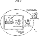
- Fig. 2 is a diagram for explaining the position of the user U supposed to be a customer of the store 200.
- an area TE to which electric wave transmitted from the antenna 21 of the transmitter 20 is reachable (hereinafter referred to "electric wave reachable area”) is formed so as to contain both the premises of the store 200 and the outside area of the premises of the store 200, for example.
- An area TS to which sound wave transmitted from the speaker 22 of the transmitter 20 is reachable (hereinafter referred to "sound wave reachable area”) is formed by the premises of the store 200, for example.
- the transmitter 20 transmits sound wave and electric wave so that the entire area of the sound wave reachable area TS is contained within the electric wave reachable area TE.
- the relative position of the user U with respect to the transmitter 20 can be classified into the following three types, that is, a "user position I", a "user position II” and a "user position III".
- the "user position I" locates the outside of the electric wave reachable area TE and also the outside of the sound wave reachable area TS.
- the "user position II" locates within the electric wave reachable area TE, but the outside of the sound wave reachable area TS.
- the "user position III" locates within the electric wave reachable area TE and also within the sound wave reachable area TS.
- the user U existing at the user position III that is, the user U existing within the sound wave reachable area TS is detected as a person having visited the store 200.
- Fig. 3 is a block diagram showing the configuration of the visit detection system 1.
- the transmitter 20 includes, as the hardware configuration thereof, the antenna 21, the speaker 22 and a transmission control unit 23.
- the transmission control unit 23 is, for example, a microcomputer which includes an arithmetic processing unit such as a CPU (Central Processing Unit), a main memory to which the arithmetic processing unit accesses, and a code memory for storing an identification code allocated to the transmitter 20.
- the identification code stored in the code memory is used for uniquely identifying the store 200 in this embodiment. This identification code is hereinafter called as a "store identification code".
- the transmission control unit 23 performs the control relating to the information transmission using electric wave and sound wave.
- the information transmission using electric wave will be explained.
- the transmission control unit 23 transmits, from the antenna 21, electric wave for performing radio communication conforming to Bluetooth (to be concrete, short range radio communication).
- the transmission control unit 23 periodically (for example, at a predetermined period) transmits, from the antenna 21, the store identification code read from the code memory according to the standard called Bluetooth LE (Low Energy).
- the transmission control unit 23 transmits, from the speaker 22, sound wave for performing audio communication.
- the transmission control unit 23 periodically (for example, at a predetermined period) transmits, from the speaker 22, the store identification code read from the code memory using the technique of an audio signal processing.
- the transmission control unit 23 modulates the store identification code by a specific spread code to thereby generate an audio signal in which the frequency of the spread code after the modulation is shifted to a higher frequency band (for more details, see WO 2010/016589 filed by the same applicant as the present application).
- the transmission control unit 23 supplies the generated audio signal on which the store identification code is superimposed to the speaker 22 to thereby transmit sound wave representing the audio signal.
- the transmission control unit 23 shifts the frequency to a frequency range which is a relatively high frequency range of an audible range not lower than a frequency (for example, 18 kHz) hardly hear for a person but less in uncomfortable feeling and unpleasant feeling and further contains the upper limit value (for example, 20 kHz) of the audible range.
- the upper limit value of the audible range may be determined based on the sampling frequency of the transmitter 20 and the terminal device 10. For example, the upper limit value of the audible range may be 22.05 kHz (when the sampling frequency is 44.1 kHz) or 24.0 kHz (when the sampling frequency is 48.0 kHz).
- the transmission control unit 23 may superimpose the store identification code on the audio signal of the audible frequency range recognizable by a person.
- the transmission control unit 23 superimposes the store identification code on the audio signal representing audible sound such as music or human voice (for example, a voice signal for guiding goods sold in the store 200 and services provided by the store).
- the frequency band on which the store identification code is superimposed may be one capable of generating sound wave from the speaker 22 and is not limited to the aforesaid frequency band.
- the transmission control unit 23 may transmit the information using sound wave, by means of OFDM (Orthogonal Frequency-Division Multiplexing) modulation or other modulation system in place of the spread spectrum modulation.
- the transmitter 20 may have a function of obtaining and updating the store identification code stored in the code memory, through the communication with the management server 30 and other external devices via a communication network.
- the terminal device 10 includes, as the hardware configuration thereof, a control unit 11, a radio communication unit 12, a microphone 13, an A/D (Analog to Digital) converter 14, a memory unit 15, a notification unit 16 and a network communication unit 17.
- the control unit 11 is a microcomputer which includes an arithmetic processing unit such as a CPU and a main memory which the arithmetic processing unit accesses.
- the control unit 11 controls the respective constituent elements of the terminal device 10 by operating programs.
- the radio communication unit 12 is an interface which includes, for example, a communication circuit and an antenna to thereby perform radio communication conforming to Bluetooth (short range radio communication).
- the radio communication unit 12 acts as an electric wave receiver for receiving electric wave transmitted from the transmitter 20.
- the microphone 13 is a sound wave detector for detecting sound wave.
- the microphone converts the detected sound wave into an audio signal of an analog format as an electrical signal and supplies the audio signal of an analog format to the A/D converter 14.
- the A/D converter 14 performs an A/D conversion processing of converting the audio signal of an analog format into an audio signal of a digital format and supplies the audio signal of a digital format to the control unit 11.
- the memory unit 15 has a memory device such as an EEPROM (Electronically Erasable and Programmable ROM) or a flash memory.
- the memory unit 15 stores, for example, a management application program MA and service application programs SA as application programs to be executed by the control unit 11.
- the management application program MA is an application program for realizing the function relating to the detection of the visit to the store.
- information representing a correspondence relation between the store identification codes and the service application programs SA is written.
- information of an access destination for example, an address of a communication destination
- the service application program SA is an application program for realizing the function relating to the service provided from the management server 30.
- information of an access destination for example, an address of a communication destination
- the service application program SA realizes a function for executing a processing for utilizing the service having been provided already (for example, a display processing of images and a data communication processing relating to the service).
- the notification unit 16 includes, for example, a vibrator and a speaker and acts as a notification unit for notifying predetermined information to the user U.
- the notification unit 16 may be a unit which generates a phenomenon perceptible by the user U to thereby notify the user U of the predetermined information.
- the network communication unit 17 is an interface which includes, for example, a communication circuit and an antenna to thereby connect to the network.
- the network communication unit 17 communicates with the management server 30 via the network.
- the terminal device 10 includes the configuration substantially same as a general smartphone such as a user interface for providing a GUI (Graphic User Interface) in addition to the aforesaid hardware configuration.
- GUI Graphic User Interface
- the control unit 11 of the terminal device 10 realizes functions corresponding to a notification control unit 111, an activation control unit 112 and a processing unit 113 by operating the management application program MA.
- the processing unit 113 includes a code processing unit 1131 which performs a code processing for obtaining the store identification code transmitted by means of sound wave from the transmitter 20.
- the notification control unit 111 (notification controller) notifies the user U of the reception of electric wave from the transmitter 20 via the notification unit 16.
- the radio communication unit 12 waits for electric wave during the operation of the management application program MA, and receives electric wave transmitted from the transmitter 20.
- the notification control unit 111 may estimate a distance between the terminal device 10 and the transmitter 20 based on the intensity of electric wave received from the transmitter 20 and notify the user of the distance. In this case, for example, the notification control unit 111 determines that the terminal device 10 is a predetermined distance or more away from the transmitter 20 on condition that the intensity of electric wave received by the radio communication unit 12 is lower than a predetermined level. Then, under the control by the notification control unit 111, the notification unit 16 notifies the user U that the terminal device 10 is the predetermined distance or more away from the transmitter 20.
- the activation control unit 112 performs an activation control of activating and stopping a sound wave reception unit 100.
- the activation control unit 112 activates the sound wave reception unit 100 to place it in a standby state for receiving sound wave, on condition that the radio communication unit 12 receives electric wave transmitted from the transmitter 20.
- the sound wave reception unit 100 (sound receiver) is a unit for receiving sound wave when it is placed in the standby state for receiving sound wave.
- the sound wave reception unit 100 is realized by the A/D converter 14 and the code processing unit 1131.
- the A/D converter 14 performs the A/D conversion processing and the code processing unit 1131 performs the code processing.
- the activation control unit 112 may estimate the distance between the terminal device 10 and the transmitter 20 based on the intensity of electric wave received from the transmitter 20 and perform the activating control according to the estimated distance. In this case, for example, the activation control unit 112 determines that the terminal device 10 is a predetermined distance or more away from the transmitter 20 to thereby stop the sound wave reception unit 100 on condition that the intensity of electric wave received by the radio communication unit 12 is lower than a predetermined level.
- the processing unit 113 performs a specific processing based on the received sound wave when the sound wave reception unit 100 receives sound wave from the transmitter 20.
- the code processing unit 1131 of the processing unit 113 extracts the modulated signal by subjecting the audio signal of a digital format supplied from the A/D converter 14 to a filtering processing, and then performs the code processing.
- the code processing unit 1131 performs a decode processing on the extracted signal to obtain the store identification code.
- the processing unit 113 activates the service application program SA corresponding to the store identification code obtained by the code processing and performs a processing based on the service application program SA thus activated.
- the processing unit 113 communicates with the management server 30 via the network communication unit 17 based on the service application program SA.
- Fig. 4 is a flowchart showing the flow of a processing performed by the terminal device 10.
- Fig. 5 is a diagram for explaining the positional change of the user U.
- the user U In a state before the terminal device 10 starts the processing operation described hereinafter based on the present invention, the user U is supposed to exist at the user position I which is the outside of the electric wave reachable area TE and also the outside of the sound wave reachable area TS.
- the control unit 11 of the terminal device 10 starts the management application program MA stored in the memory unit 15 and starts the reception of electric wave by the radio communication unit 12 (step S1).
- the control unit 11 may activate the management application program MA according to the operation by the user U or operate the management application program MA in the background.
- the control unit 11 tries to perform the processing of obtaining the store identification code from electric wave received by the radio communication unit 12.
- control unit 11 determines whether or not the radio communication unit 12 receives electric wave from the transmitter 20 (step S2). In the processing of step S2, the control unit 11 determines the presence or absence of the reception of electric wave from the transmitter 20 depending on whether or not the store identification code is obtained from the received electric wave. As shown in Fig.5 , when the user U exists at the user position I, the control unit 11 determines "NO" in the processing of step S2 and waits for the reception.
- the control unit 11 obtains the store identification code from electric wave received from the transmitter 20 and determines that electric wave is received from the transmitter 20 (YES in step S2).
- the control unit 11 notifies the user U of the reception of electric wave from the transmitter 20 by means of the notification unit 16 (step S3).
- the control unit 11 operates the vibrator or drives the speaker to thereby output predetermined sound (for example, ring alert or alarm tone). Even if the terminal device 10 is placed within the pocket or the bag etc.
- the user U recognizes the notification from the terminal device 10
- the user may take out and hold the terminal device 10 even when the terminal device 10 is placed within the pocket or the bag etc.
- an icon or the like may be displayed on a screen of the terminal device 10 to indicate that the electric wave is received from the transmitter 20.
- step S4 the control unit 11 activates the sound wave reception unit 100 to thereby place it in the standby state for receiving sound wave (step S4).
- the control unit 11 activates the A/D converter 14 so as to start the A/D conversion processing and also starts the code processing.
- the control unit 11 notifies the user U of this fact and activates the sound wave reception unit 100 to thereby place it in the standby state for receiving sound wave.
- the sound wave reception unit 100 is activated and placed in the standby state for receiving sound wave, for example, an icon etc.
- control unit 11 specifies the service application program SA, having the corresponding relation to the store identification code obtained by the reception of electric wave, based on the management application program MA and activates the specified service application program SA. Then, the control unit 11 is placed in a state of executing a processing based on the service application program SA thus activated.
- step S5 determines whether or not sound wave from the transmitter 20 is received.
- step S5 the control unit 11 determines presence or absence of the reception of sound wave from the transmitter 20 depending on whether or not the sound wave reception unit 100 obtains the store identification code.
- the control unit 11 determines "NO" in the processing of step S5 and waits for the reception.
- the control unit 11 determines that the sound wave reception unit 100 obtains the store identification code and sound wave is received from the transmitter 20 (YES in step S5).
- the control unit 11 communicates with the management server 30 via the network communication unit 17 according to the service application program SA being operated, and executes a predetermined processing based on the service application program SA (step S6).
- the control unit 11 accesses the management server 30 via the network communication unit 17 using a communication address designated by the service application program SA.
- the control unit 11 communicates with the management server 30 via the network communication unit 17 to thereby perform a processing based on the service application program SA as will be explained with reference to Fig. 6 .
- Fig. 6 is a sequence chart showing the processing based on the service application program SA, performed between the terminal device 10 and the management server 30.
- the control unit 11 of the terminal device 10 accesses the management server 30 via the network communication unit 17 and transmits data representing visiting situation to the management server 30 (step S61).
- the visiting situation data represents the situation of visit of the user U and includes, for example, the terminal identification information (for example, telephone number) specific to the terminal device 10 and the store identification code obtained by the code processing.
- the control unit 11 transmits the visiting situation data to the management server 30 each time the store identification code transmitted from the transmitter 20 is obtained or each predetermined time interval while the store identification code is obtained continuously.
- the management server 30 detects the visit of the user U carrying the terminal device 10 to the store, based on the visiting situation data received from the terminal device 10 (step S62). In the processing of step S62, the management server 30 performs a database processing of storing the visit detection result in a database. In the database processing, the management server 30 stores, in the database, visit history information representing a visit history in association with the terminal identification information and the store identification code.
- the visit history information includes, for example, at least one of visiting date and time, staying time in the store 200, and the number of visit to the store.
- the management server 30 transmits service data representing the predetermined service to the terminal device 10 in the case of providing a service to the user U as a response to the reception of the visiting situation data (step S63).
- the service provided to the user U by the management server 30 includes, for example, at least one of the provision of a coupon or a monetary value such as a point corresponding to the visit, the transmission of a message for guiding the user U to a web shop (for example, URL (Uniform Resource Locator) of a web page), and the distribution of contents (for example, advertisement contents for guiding goods or services to the user).
- a web shop for example, URL (Uniform Resource Locator) of a web page
- contents for example, advertisement contents for guiding goods or services to the user.
- the concrete kinds of the services are not limited to these examples.
- the management server 30 performs a predetermined processing generated at the time of providing the service to the terminal device 10, in the case of transmitting the service data to the terminal device 10. This processing is, for example,
- control unit 11 of the terminal device 10 When the control unit 11 of the terminal device 10 receives the service data from the management server 30 via the network communication unit 17, the control unit 11 stores the received service data in the memory unit 15. In the case where the user U utilizes the service thus provided, the control unit 11 reads the service data from the memory unit 15 during the execution of the service application program SA to thereby perform a processing for utilizing the service (for example, the display processing and the communication processing).
- Fig. 7 is a flowchart showing the flow of a processing performed by the terminal device 10.
- Fig. 8 is a diagram for explaining the positional change of the user U. In a state before the terminal device 10 starts the operation described hereinafter, the user U is supposed to exist at the user position III.
- the control unit 11 of the terminal device 10 determines whether or not the reception by the radio communication unit 12 of electric wave transmitted from the transmitter 20 has stopped (step S11). As shown in Fig. 8 , when the user exists within the electric wave reachable area TE (that is, at the user position II or the user position III), the control unit 11 obtains the store identification code from the electric wave received from the transmitter 20. Thus, the control unit 11 determines "NO" in the processing of step S11 and the processing is waited.
- step S11 determines that the reception of electric wave transmitted from the transmitter 20 has stopped.
- step S12 the notification unit 16 notifies the user U that the reception of electric wave transmitted from the transmitter 20 has stopped.
- step S12 the control unit 11 performs the notification to the user U in the same manner as the processing of step S3.
- control unit 11 determines whether or not a set time elapses after the reception of electric wave by the radio communication unit 12 stops or after the notification is made to the user U by the processing of step S12 (step S13).
- This set time is 5 seconds, for example, but may be a time other than 5 seconds. Further, this set time may be fixed or set by the user U.
- step S13 When it is determined that the set time does not elapse (NO in step S13), the control unit 11 determines whether or not the radio communication unit 12 receives electric wave from the transmitter 20 (step S14). When the control unit 11 determines that electric wave from the transmitter 20 is not received (NO in step S14), the processing is returned to step S13. Thereafter, when the control unit 11 determines that the set time elapses without receiving electric wave from the transmitter 20 (YES in step S13), the control unit 11 stops the sound wave reception unit 100 (step S15). As shown by "notification” and "stop” in Fig.
- control unit 11 performs the notification to the user U when the user U moves to the outside of the electric wave reachable area TE from the inside of the electric wave reachable area TE, and further stops the sound wave reception unit 100 when the set time elapses thereafter.
- control unit 11 may exit the management application program MA and the service application program SA each being operated.
- step S14 when the control unit 11 determines that electric wave from the transmitter 20 is received before the set time elapses (YES in step S14), the processing is returned to step S11. That is, the control unit 11 maintains the sound wave reception unit 100 in the standby state for receiving sound wave. For example, as shown by an arrow of a broken line in Fig. 8 , when the user U temporarily moves to the outside of the electric wave reachable area TE and then returns within the electric wave reachable area TE before the set time elapses, the terminal device 10 receives again electric wave from the transmitter 20.
- the control unit 11 maintains the sound wave reception unit 100 in the standby state for receiving sound wave.
- the terminal device 10 may again receive electric wave from the transmitter 20 before the set time elapses.
- the terminal device 10 determines that the user arrives at an area (that is, user position II) close to the area (that is, user position III) to which the information transmitted from the transmitter 20 using sound wave is reachable. Then, the terminal device 10 notifies the user U of this determination and activates the sound wave reception unit 100.
- the user U recognizes according to the notification from the terminal device 10 that the user approaches the area to which sound wave transmitted from the transmitter 20 is reachable, the user sets the terminal device 10 to a sound wave receivable state (that is, user position III). According to this operation of the user U, the terminal device 10 is placed in the state capable of receiving the information transmitted from the transmitter 20 using sound wave.
- the terminal device 10 can receive sound wave from the transmitter 20 when the user approaches the transmitter 20.
- the terminal device 10 can reduce the time period of the standby state for receiving sound wave to thereby reduce power consumption.
- the power consumption of the electric wave waiting state is smaller than that of the sound wave waiting state.
- the power consumption is small even when the terminal device 10 continues the standby state for receiving electric wave.
- the visit detection system 1 according to the second embodiment which is not forming part of the invention as claimed, will be explained.
- the visit detection system 1 according to the second embodiment differs from the first embodiment in a point that the terminal device 10 activates the sound wave reception unit 100 when it is determined that the terminal device 10 is in a sound wave receivable state after the reception of electric wave from the transmitter 20.
- the configurations and the operations of the transmitter 20 and the management server 30 in this embodiment are same as those of the first embodiment.
- Fig. 9 is a block diagram showing the configuration of the terminal device 10. As shown in Fig. 9 , the terminal device 10 according to this embodiment includes a sensor unit 18 in addition to the configuration explained in the first embodiment.
- the sensor unit 18 is a sensor for detecting whether or not the terminal device 10 is in a sound wave receivable state.
- the sensor unit 18 is a brightness sensor for detecting the brightness of the surrounding (periphery) of the terminal device 10.
- the sensor unit 18 detects light quantity representing the surrounding brightness of the terminal device 10 and supplies light quantity data representing the detected light quantity to the control unit 11.
- the control unit 11 realizes a determination unit 114 in addition to the functional configuration explained in the first embodiment by operating the management application program MA.
- the determination unit 114 determines whether or not the terminal device 10 is in the sound wave receivable state.
- the determination unit 114 determines that the terminal device 10 is in the sound wave receivable state. This is because, when the terminal device 10 is placed in a relatively bright environment, it is supposed that the user U holds the terminal device 10 by the hand.
- the determination unit 114 determines that the terminal device 10 is not in the sound wave receivable state.
- the terminal device 10 is placed in a relatively dark environment, it is supposed that the user U carries the terminal device 10 within a place such a pocket or a bag or supposed that the user U does not carry the terminal device 10.
- Fig. 10 is a flowchart showing the flow of a processing performed by the terminal device 10.
- the control unit 11 of the terminal device 10 executes the processing of steps S1 to S3, whereby the radio communication unit 12 receives electric wave from the transmitter 20 and the user U is notified of the reception of electric wave. Then, it is determined whether or not the terminal device 10 is in the sound wave receivable state (step S7). When the light quantity represented by the light quantity data supplied from the sensor unit 18 is less than the threshold value, the control unit 11 determines "NO" in the processing of step S7 and waits.
- step S7 determines "YES" in the processing of step S7 and the processing proceeds to step S4. That is, after the electric wave is received from the transmitter 20 and the user U is notified of the reception of electric wave, when the control unit 11 determines that the terminal device 10 is in the sound wave receivable state, the control unit 11 activates the sound wave reception unit 100 to thereby place it in the standby state for receiving sound wave. Thereafter, the control unit 11 executes the processing of steps S5 and S6 by the same procedure as the first embodiment.
- the terminal device 10 activates the sound wave reception unit 100 when the terminal device 10 is placed in the state substantially capable of receiving sound wave from the transmitter 20.
- the terminal device 10 can save the unnecessary power consumption corresponding to a period during which the terminal device 10 is not in the sound wave receivable state and hence the sound wave reception unit 100 is not activated.
- the sensor unit 18 may be realized by a sensor other than the brightness sensor.
- the sensor unit 18 may be realized by one of an acceleration sensor, an inclination sensor, a geomagnetism sensor and an attitude sensor, as a sensor for detecting the change of the posture of the terminal device 10. This is because when the user U holds the terminal device 10 by the hand, the posture of the terminal device 10 highly likely changes according to the movement of the hand of the user U. In this case, when the sensor unit 18 detects the posture change satisfying a predetermined condition, the determination unit 114 of the control unit 11 determines that the terminal device 10 is in the sound wave receivable state.
- the sensor unit 18 may be realized by a sensor which detects a force acting on the casing of the terminal device 10 when the user U holds the terminal device 10 by the hand. In this case, when the sensor unit 18 detects a force equal to or larger than a threshold value acting on the casing of the terminal device 10, the determination unit 114 determines that the terminal device 10 is in the sound wave receivable state.
- the determination unit 114 may determine whether or not the terminal device 10 is in the sound wave receivable state without using the detection result of the sensor unit 18. In this case, the terminal device 10 may not include the sensor unit 18. For example, when the terminal device 10 is in an operation state where the user U operates the terminal device 10 or in a display state where the terminal device 10 displays an image on the screen, the determination unit 114 determines that the terminal device 10 is in the sound wave receivable state.
- the concrete method of realizing the determination performed by the determination unit 114, as to whether or not the terminal device 10 is in the sound wave receivable state is not particularly limited.
- a distance between a data transmission point and a data reception point can be estimated (calculated) based on the intensity of a received signal (that is, reception intensity of electric wave) at the time of receiving the data.
- the terminal device 10 operates according to the distance from the transmitter 20 based on electric wave received from the transmitter 20.
- the hardware configurations of the terminal device 10, the transmitter 20 and the management server 30 in this embodiment are same as those of the first embodiment.
- the operations of the transmitter 20 and the management server 30 in this embodiment are same as those of the first embodiment.
- Fig. 11 is a diagram for explaining the positional change of the user U.
- the electric wave reachable area TE is configured by an electric wave reachable area TE1 in which the reception intensity of electric wave from the transmitter 20 is relatively high and an electric wave reachable area TE2 in which the reception intensity of electric wave from the transmitter 20 is relatively low.
- the electric wave reachable area TE1 is smaller in the distance from the transmitter 20 than the electric wave reachable area TE2.
- the reception intensity of electric wave in the electric wave reachable area TE1 is represented by "high” and the reception intensity of electric wave in the electric wave reachable area TE2 is represented by "low”.
- the electric wave reachable areas TE1 and TE2 may be classified based on an arbitrary level of the reception intensity.
- Fig. 12 is a flowchart showing the flow of a processing performed by the terminal device 10.
- the control unit 11 of the terminal device 10 executes the processing of steps S1 to S3, whereby the radio communication unit 12 receives electric wave from the transmitter 20 and then the user U is notified of the reception of electric wave.
- the control unit 11 notifies the user U of the reception of electric wave when the user U moves within the electric wave reachable area TE2 from the outside of the electric wave reachable area TE2.
- step S8 determines whether or not the reception intensity of electric wave is "high” (step S8). In other words, the control unit 11 determines whether or not the user U moves within the electric wave reachable areas TE1.
- the control unit 11 determines that the reception intensity of electric wave from the transmitter 20 is not "high”, that is, the reception intensity is "low” or electric wave is not received (NO in step S8), the processing is waited.
- the control unit 11 determines that the reception intensity of electric wave from the transmitter 20 is "high” (YES in step S8), the processing proceeds to step S4.
- control unit 11 activates the sound wave reception unit 100 to thereby place it in the standby state for receiving sound wave. Then, the control unit 11 executes the processing of steps S5 and S6 by the same procedure as the first embodiment.
- Fig. 13 is a flowchart showing the flow of a processing performed by the terminal device 10.
- the control unit 11 determines whether or not the reception intensity of electric wave transmitted from the transmitter 20 is "high" (step S16).
- the control unit 11 determines "YES” in the processing of step S16 and the processing is waited. Thereafter, when the user U moves within the electric wave reachable area TE2, the control unit 11 determines that the reception intensity of electric wave transmitted from the transmitter 20 is not "high” (NO in step S16), and the notification is made by the notification unit 16 to the user U (step S12).
- the control unit 11 determines whether or not the radio communication unit 12 receives electric wave from the transmitter 20 (step S17). When the control unit 11 determines that electric wave from the transmitter 20 is received (YES in step S17), the processing is waited. In contrast, when the control unit 11 determines that the reception of electric wave from the transmitter 20 has stopped (NO in step S17), the control unit 11 stops the sound wave reception unit 100 (step S15). As shown in Fig. 11 , the control unit 11 stops the sound wave reception unit 100 when the user U moves to the outside of the electric wave reachable area TE1 from the inside of the electric wave reachable area TE1.
- the terminal device 10 activates the sound wave reception unit 100 when it is determined that the distance from the transmitter 20 is less than the predetermined distance based on the reception intensity of electric wave from the transmitter 20. Since the terminal device 10 activates the sound wave reception unit 100 after the user approaches the area capable of receiving sound wave, the power consumption in the standby state for receiving sound wave can be further reduced. Further, when the user U leaves the store, in the case where it is determined that the distance from the transmitter 20 is the predetermined distance or more based on the reception intensity of electric wave from the transmitter 20, the user U is notified of this determination. Thus, the terminal device 10 can perform the notification to the user U and stop the sound wave reception unit 100 more quickly than the first embodiment.
- This operation of the terminal device 10 according to the distance between the terminal device 10 and the transmitter 20 explained in the third embodiment may be applied to the terminal device 10 explained in the second embodiment.
- the present invention may be implemented in modes different from the aforesaid embodiments.
- the present invention may be implemented according to modified examples 1 and 6.
- the invention as claimed does not cover modified examples 2, 3, 4, 5, 7, 8 and 9.
- Fig. 14 is a diagram for explaining a relation between the position of the user U and the operation of the terminal device 10.
- activation and notification means a timing at which the notification to the user U and the activation of the sound wave reception unit 100 is performed in the case where electric wave from the transmitter 20 is received.
- Notification means a timing at which the notification to the user U is performed before the sound wave reception unit 100 stops.
- “Stop” means a timing at which the sound wave reception unit 100 is stopped.
- the control unit 11 of the terminal device 10 when it is determined that the user U moves to the outside of the electric wave reachable area TE and the reception of electric wave from the transmitter 20 has stopped, the control unit 11 of the terminal device 10 notifies the user U of the determination and stops the sound wave reception unit 100.
- the control unit 11 of the terminal device 10 when it is determined that the user U moves to the outside of the sound wave reachable area TS and the reception of sound wave from the transmitter 20 has stopped, the control unit 11 of the terminal device 10 notifies the user U of the determination. Further, when it is determined that electric wave from the transmitter 20 is not received, the control unit 11 stops the sound wave reception unit 100.
- the (operation example 3) differs from the (operation example 2) in a point that when a set time elapses after it is determined that the reception of electric wave from the transmitter 20 has stopped, the control unit 11 stops the sound wave reception unit 100.
- the user U may selectively set one of the first embodiment and these operation examples 1 to 3 by which the terminal device 10 is to be operated.
- Fig. 15 is a diagram for explaining a relation between the position of the user U and the operation of the terminal device 10.
- the control unit 11 of the terminal device 10 notifies the user U of the determination. Then, the control unit 11 stops the sound wave reception unit 100 when a set time elapses after it is determined that the reception of electric wave from the transmitter 20 has stopped. In the (operation example 5), when it is determined that the reception of sound wave from the transmitter 20 has stopped, the control unit 11 notifies the user U of the determination. Then, the control unit 11 stops the sound wave reception unit 100 when it is determined that the reception intensity of electric wave from the transmitter 20 changes from "high” to "low”.
- the (operation example 6) differs from the (operation example 5) in a point that when a set time elapses after it is determined that the reception intensity of electric wave from the transmitter 20 changes from "high” to "low", the control unit 11 stops the sound wave reception unit 100.
- the user U may selectively set one of the third embodiment and these operation examples 4 to 6 by which the terminal device 10 is to be operated.
- electric wave reachable areas formed by two or more stores may be overlapped.
- Fig. 16 is diagram for explaining the position of the user U. As shown in Fig. 16 , it is supposed that a store 200A and a store 200B are close to each other. A transmitter 20A and a transmitter 20B are installed within the store 200A and the store 200B, respectively.
- the transmitter 20A forms an electric wave reachable area TEA and a sound wave reachable area TSA.
- the transmitter 20B forms an electric wave reachable area TEB and a sound wave reachable area TSB. Further, the electric wave reachable area TEA and the electric wave reachable area TEB are partially overlapped to form an overlapped area Tov.
- the terminal device 10 carried by the user U existing in the overlapped area Tov receives electric wave from each of the transmitters 20A and 20B.
- the control unit 11 of the terminal device 10 activates the service application program SA based on electric wave from one of the transmitters 20A and 20B corresponding to the higher reception intensity of electric wave. This is because it is supposed that the user U most likely exists within the store or is going to visit this store in which the transmitter corresponding to the higher reception intensity of electric wave is installed.
- the terminal device 10 existing in the overlapped area Tov may obtain the store identification codes based on electric wave received from the transmitters 20A and 20B and activate the service application program SA based on the obtained two store identification codes.
- the terminal device 10 may also activate the service application program SA based on electric wave from one of the transmitters 20 corresponding to the highest reception intensity of electric wave.
- the terminal device 10 may obtain store identification codes based on electric wave received from all the transmitters and activate the service application program SA.
- the visit detection system 1 may detect the visit to the store based on optical wave instead of sound wave.
- Optical wave also differs from electric wave in an ability of penetrating an obstacle such as a wall, a door or a partition, for example.
- optical wave has physical properties that it is lower in penetrating ability, more excellent in straight travelling properties and less likely diffracts.
- the configuration relating to sound wave of the visit detection system 1 according to each of the aforesaid embodiments may be replaced by configuration relating to optical wave.
- the explanation will be made as to a case where the configuration relating to sound wave of the visit detection system 1 according to the first embodiment is replaced by the configuration relating to optical wave.
- Fig. 17 is a block diagram showing the entire configuration of the visit detection system 1 according to this modified example.
- the transmitter 20 includes a light emission unit 24 as an optical wave transmission unit emitting optical wave, in place of the speaker 22.
- the terminal device 10 receives optical wave transmitted from the light emission unit 24 of the transmitter 20.
- An area TL to which optical wave transmitted from the light emission unit 24 of the transmitter 20 is reachable (hereinafter referred to "optical wave reachable area") is contained within the premises of the store 200, for example, and the entirety of this area is contained within the electric wave reachable area TE.
- Fig. 18 is a block diagram showing the configuration of the visit detection system 1.
- the transmitter 20 includes the antenna 21, the light emission unit 24 and the transmission control unit 23.
- the light emission unit 24 is, for example, a light emitting diode (LED) and transmits optical wave according to the control of the transmission control unit 23.
- the transmission control unit 23 controls the information transmission using electric wave and optical wave. The information transmission using optical wave will be explained.
- the transmission control unit 23 transmits, from the light emission unit 24, optical wave formed by blinking an infrared ray or a visible ray, for example.
- the transmission control unit 23 transmits optical wave uniquely related to the store identification code to be distributed.
- the terminal device 10 includes an imaging unit 19 in place of the microphone 13 and the AID converter 14 explained in the first embodiment.
- the imaging unit 19 is an imaging device (digital camera) for performing imaging.
- the imaging unit performs an imaging processing of generating imaged data representing an imaged image and supplying the data to the control unit 11.
- the control unit 11 operates the management application program MA to thereby realize functions corresponding to a notification control unit 111, an activation control unit 112a and a processing unit 113a.
- the processing unit 113a realizes a code processing unit 1131a which performs a code processing for obtaining the store identification code transmitted from the transmitter 20 by means of optical wave.
- the activation control unit 112a activates an optical wave reception unit 100a to thereby place it in a standby state for receiving optical wave on condition that electric wave transmitted from the transmitter 20 is received by the radio communication unit 12.
- the optical wave reception unit 100a is a unit (optical wave receiver) for receiving optical wave when it is placed in the standby state for receiving optical wave.
- the optical wave reception unit 100a is realized by the imaging unit 19 and the code processing unit 1131a.
- the imaging unit 19 performs the imaging processing and the code processing unit 1131a performs the code processing.
- the processing unit 113a When the optical wave reception unit 100a receives optical wave from the transmitter 20, the processing unit 113a performs a particular processing based on the received optical wave.
- the code processing unit 1131a of the processing unit 113a performs the code processing of analyzing the imaged data supplied from the imaging unit 19 to thereby obtain the store identification code.
- the processing unit 113a activates the service application program SA corresponding to the store identification code obtained by the code processing and performs a processing based on the activated service application program SA.
- Fig. 19 is a flowchart showing the flow of a processing performed by the terminal device 10.
- the control unit 11 of the terminal device 10 executes the processing of steps S1 to S3, whereby the radio communication unit 12 receives electric wave from the transmitter 20 and the user U is notified of the reception of electric wave.
- the optical wave reception unit 100a is activated and is placed in the standby state for receiving optical wave (step S4a).
- the control unit 11 specifies, based on the management application program MA, the service application program SA corresponding to the store identification code obtained by the reception of electric wave, and activates the specified service application program.
- the control unit 11 determines whether or not optical wave from the transmitter 20 is received by the optical wave reception unit 100a (step S5a).
- step S5a the control unit 11 determines presence or absence of the reception of optical wave from the transmitter 20 depending on whether or not the optical wave reception unit 100a obtains the store identification code by the code processing.
- the control unit 11 waits until it is determined that optical wave from the transmitter 20 is received (NO in step S5a). Thereafter, when the user U moves within the optical wave reachable area TL and turns the imaging unit 19 toward the light emission unit 24 of the transmitter 20, the control unit 11 determines that optical wave from the transmitter 20 is received (YES in step S5a). Then, the control unit 11 executes the processing of step S6 by the same procedure as the first embodiment, based on the store identification code obtained by the code processing.
- Fig. 20 is a flowchart showing the flow of a processing performed by the terminal device 10.
- the control unit 11 determines whether or not the reception of electric wave from the transmitter 20 has stopped when the imaging unit 19 is placed in the standby state for receiving optical wave (step S11).
- the control unit 11 determines "NO" in the processing of step S11 and notifies the user U by means of the notification unit 16 that the reception of electric wave from the transmitter 20 has stopped (step S12).
- the control unit 11 determines whether or not a set time elapses after the reception of electric wave by the radio communication unit 12 stops or the notification is made to the user U by the processing of step S12 (step S13).
- step S14 When it is determined that electric wave from the transmitter 20 is not received (NO in step S14), the control unit 11 repeats the processing of step S13 and step S14 (NO in step S13 ⁇ NO in step S14 ⁇ NO in step S13 ...), until the set time elapses.
- the control unit 11 stops the optical wave reception unit 100a (step S15).
- the process returns to the processing of step S11.
- the configuration relating to optical wave in place of the configuration relating to sound wave may also be applied to the visit detection system 1 of each of the second and third embodiments, and also the aforesaid respective modified examples.
- the configuration and operation of the visit detection system 1 thus applied with this configuration relating to optical wave will be estimated from the explanation of this modified example.
- the sound wave reception unit 100 includes the A/D converter 14 and the code processing unit 1131
- the A/D converter 14 may be omitted.
- the control unit 11 may obtain an audio signal of a digital format from the A/D converter 14 based on sound wave detected by the microphone 13. Even in this case, when the sound wave reception unit 100 stops, since the code processing unit 1131 does not perform the code processing based on the received audio signal, the power consumption of the terminal device 10 an be reduced.
- the control unit 11 may determine whether or not the terminal device 10 exists within the sound wave receivable area based on the audio signal supplied from the microphone 13 during stop of the sound wave reception unit 100. For example, when the control unit 11 detects, based on the audio signal supplied from the microphone 13, sound satisfying a predetermined condition generated at the time of taking out the terminal device 10 from a pocket or a bag, it is determined that the terminal device 10 exists within the sound wave receivable area.
- the optical wave reception unit 100a according to the modified example 4 includes the imaging unit 19 and the code processing unit 1131a, the imaging unit 19 may be omitted. Even in this case, when the sound wave reception unit 100 stops, since the code processing unit 1131a does not perform the code processing based on the received imaged data, the power consumption of the terminal device 10 can be reduced.
- the visit detection system 1 may detect, for example, the visit of a person to places explained below as well as the visit of a person to the store 200.
- the visit detection system 1 may detect that a person visits a place where many and unspecified persons get in and out, such as a commercial facility other than a store like an amusement park, a public facility such as a station or a town hall, an office or a hotel lobby.
- the visit detection system 1 may detect that a person visits a predetermined position (check point) in a stamp rally or a walk rally, for example.
- the visit detection system 1 may detect that a person visits a place where specified persons get in and out, such as a company, a factory or a house.
- the transmitter 20 is merely required to transmit the store identification code for uniquely identifying the own device or the installation place thereof using electric wave or sound wave.
- the transmitter 20 may transmits different information for each of these areas.
- the transmitter 20 may transmit, among plural information related hierarchically, the information of an upper level using electric wave and the information of a lower level using sound wave.
- the transmitter 20 is installed in a vehicle such as a train or a bus (or various kinds of vehicles or various kinds of transport instruments) and transmits information.
- the transmitter 20 transmits, to the terminal device 10 of the user U exiting in each of the respective areas, information usable for the user U corresponding to the existing area.
- the transmitter 20 transmits, from the antenna 21, information such as destination of the vehicle and transfer guide including main route points (for example, stations or bus stops) towards the external space at the periphery of the vehicle (for example, space near the entrance) and the interior space of the vehicle (for example, passenger compartment).
- the transmitter 20 transmits, from the speaker 22, information such as a next stop and geometrical information near the next stop toward the interior space of the vehicle. In this respect, the transmitter 20 does not transmit information from the speaker 22 toward the external space at the periphery of the vehicle.
- the visiting situation data transmitted to the management server 30 from the terminal device 10 may include various kinds of information usable for the marketing relating to the store.
- the terminal device 10 may contain, within the visiting situation data, user specifying information (for example, user ID or name) capable of specifying the user U and user attribute information representing the attribute of the user U.
- the user attribute information is information such as age, sex, occupation and hobby.
- the terminal device 10 may contain settlement information representing the settlement state (purchased commodity and payment) within the visiting situation data.
- the terminal device 10 may transmit to the management sever 30 the visiting situation data representing a visiting situation specified based on electric wave as well as the visiting situation specified based on sound wave.
- the management server 30 can detect more detailed visiting situation of the user U such as whether or not the user actually visits the store 200 and whether or not the user drops in the store but does not actually enter therein.
- the management server 30 may analyze the visiting situation data received from the terminal device 10 to thereby generate information relating to the marketing and output the generated information to a predetermined output destination such as a computer device of a marketing company.
- the transmitter 20 and the terminal device 10 may perform radio communication (for example, short rang radio communication) conforming to the communication standard other than Bluetooth.
- the transmitter 20 may transmit from the antenna 21 electric wave for performing the radio communication conforming to the Wi-Fi standard or other wireless LAN (Local Area Network) standard.
- the transmitter may be realized so as to be separately provided with a transmitter (electric wave transmitter) which transmits electric wave and a transmitter (sound wave transmitter) which transmits sound wave.
- the electric wave transmitter and the sound wave transmitter may be installed at different positions within the store 200.
- the transmitter 20 may include a plurality of antennas having different transmission intensities of electric wave to transmit different identification codes from these antennas, respectively.
- the terminal device 10 can estimate the distance to the predetermined transmitter 20 (that is, transmission position) not based on the reception intensity of electric wave but based on the identification code received from the predetermined transmitter.
- the medium of the transmission path of electric wave and sound wave transmitted from the transmitter 20 is not limited to gaseous body such as air but may contain solid body or liquid.
- the visit detection system 1 may include a plurality of the transmitters 20 so as to detect the visit of the user U to a plurality of the stores 200. Further, a plurality of the transmitters 20 may be installed within the premises of the store 200. In this case, these transmitters 20 transmit different identification codes respectively from different areas (for example, counters) within the premises of the store 200.
- the terminal device 10 may perform a processing other than the code processing based on the received sound wave.
- the terminal device 10 may perform a voice recognition processing or an analysis processing of acoustic fingerprint.
- the terminal device 10 activates the sound wave reception unit 100 after the notification to the user U when the user U visits the store
- the present examples are not limited thereto.
- the notification to the user U and the activation of the sound wave reception unit 100 may be performed simultaneously, or the notification to the user U may be performed after the activation of the sound wave reception unit 100.
- the terminal device 10 may omit the notification to the user U in the case of stopping the sound wave reception unit 100.
- the terminal device 10 performs the activation of the sound wave reception unit 100 but may not perform the stopping of the sound wave reception unit 100.
- the terminal device 10 is not limited to the smartphone and may be other terminal device portable by the user (that is, portable terminal device) such as a mobile phone terminal, a tablet terminal, a personal computer, a PDA (Personal Digital Assistant), a mobile computer, a portable game machine or a portable music player.
- portable terminal device such as a mobile phone terminal, a tablet terminal, a personal computer, a PDA (Personal Digital Assistant), a mobile computer, a portable game machine or a portable music player.
- each of the control unit 11 of the terminal device 10 and the 23 of the transmitter 20 may be realized by the combination of a plurality of programs or the cooperation of a plurality of hardware resources.
- the programs may be distributed via a network or may be provided in a state of being stored in a computer readable recording medium such as a magnetic recording medium (a magnetic tape, a magnetic disc (HDD (Hard Disk Drive), an FD (Flexible Disc) etc.), an optical recording medium (an optical disc etc.), a magnetooptical recording medium or a semiconductor memory.
Landscapes
- Engineering & Computer Science (AREA)
- Physics & Mathematics (AREA)
- General Physics & Mathematics (AREA)
- Radar, Positioning & Navigation (AREA)
- Remote Sensing (AREA)
- Computer Networks & Wireless Communication (AREA)
- Signal Processing (AREA)
- Mobile Radio Communication Systems (AREA)
- Telephonic Communication Services (AREA)
- Management, Administration, Business Operations System, And Electronic Commerce (AREA)
- Telephone Function (AREA)
Applications Claiming Priority (1)
| Application Number | Priority Date | Filing Date | Title |
|---|---|---|---|
| JP2013227507A JP6160447B2 (ja) | 2013-10-31 | 2013-10-31 | 端末装置及びプログラム |
Publications (2)
| Publication Number | Publication Date |
|---|---|
| EP2869080A1 EP2869080A1 (en) | 2015-05-06 |
| EP2869080B1 true EP2869080B1 (en) | 2022-05-11 |
Family
ID=51903764
Family Applications (1)
| Application Number | Title | Priority Date | Filing Date |
|---|---|---|---|
| EP14190863.2A Active EP2869080B1 (en) | 2013-10-31 | 2014-10-29 | Method of controling a terminal device and program |
Country Status (6)
| Country | Link |
|---|---|
| US (1) | US20150117160A1 (ja) |
| EP (1) | EP2869080B1 (ja) |
| JP (1) | JP6160447B2 (ja) |
| KR (1) | KR101711064B1 (ja) |
| CN (1) | CN104601250B (ja) |
| TW (1) | TWI615788B (ja) |
Families Citing this family (14)
| Publication number | Priority date | Publication date | Assignee | Title |
|---|---|---|---|---|
| US10051412B2 (en) * | 2015-02-25 | 2018-08-14 | Ricoh Company, Ltd. | Locational information transmission system, locational information transmission apparatus, and information processing device |
| JP6891946B2 (ja) * | 2015-05-19 | 2021-06-18 | 株式会社リコー | 情報処理システム、情報端末、及びプログラム |
| JP6631038B2 (ja) * | 2015-05-19 | 2020-01-15 | 株式会社リコー | 情報処理装置、情報処理システム、情報管理方法、及びプログラム |
| JP6505615B2 (ja) * | 2016-01-15 | 2019-04-24 | 株式会社リクルート | 情報管理装置及び情報管理方法 |
| JP6907456B2 (ja) * | 2015-08-10 | 2021-07-21 | 株式会社リコー | 出力装置、位置情報管理システム、位置情報の管理方法、及びプログラム |
| JP6620551B2 (ja) * | 2015-12-25 | 2019-12-18 | 株式会社リコー | 出力装置、情報提供システム、音波の出力制御方法、及びプログラム |
| CN106210294B (zh) * | 2016-06-30 | 2019-10-25 | 北京小米移动软件有限公司 | 屏幕状态切换控制方法及装置 |
| CN106896356B (zh) * | 2016-08-17 | 2019-11-19 | 阿里巴巴集团控股有限公司 | 确定距离变化的方法、位置提示方法及其装置和系统 |
| CN106355394A (zh) * | 2016-08-22 | 2017-01-25 | 广西咪付网络技术有限公司 | 一种基于移动智能终端传感器控制支付的方法 |
| JP6666227B2 (ja) * | 2016-09-30 | 2020-03-13 | 株式会社Nttドコモ | 判定装置 |
| JP6923860B2 (ja) * | 2017-04-17 | 2021-08-25 | 株式会社スマート・ソリューション・テクノロジー | 通信システム、通信方法、及びプログラム |
| JP7286329B2 (ja) * | 2018-01-31 | 2023-06-05 | 株式会社東芝 | 無線システム |
| JP7121963B2 (ja) * | 2020-09-29 | 2022-08-19 | 株式会社パークランド | 広告システム |
| JP7129743B1 (ja) | 2021-07-01 | 2022-09-02 | 株式会社電通 | 店舗アプリケーション制御装置、店舗アプリケーション制御方法及び店舗アプリケーション制御プログラム |
Family Cites Families (13)
| Publication number | Priority date | Publication date | Assignee | Title |
|---|---|---|---|---|
| US8952895B2 (en) * | 2011-06-03 | 2015-02-10 | Apple Inc. | Motion-based device operations |
| JP4535857B2 (ja) * | 2004-11-30 | 2010-09-01 | スズキ株式会社 | 車両共同利用システム |
| JP4634878B2 (ja) * | 2005-07-07 | 2011-02-16 | 株式会社東芝 | 無線通信装置 |
| DE602007004185D1 (de) * | 2007-02-02 | 2010-02-25 | Harman Becker Automotive Sys | System und Verfahren zur Sprachsteuerung |
| US20090049610A1 (en) * | 2007-08-20 | 2009-02-26 | Hill-Rom Services, Inc. | Proximity activation of voice operation of hospital bed |
| US7710824B1 (en) * | 2007-09-18 | 2010-05-04 | Sprint Communications Company L.P. | Location monitoring and sonar determination of presence |
| EP2065726B9 (en) * | 2007-11-13 | 2012-04-25 | Universitetet I Oslo | Ultrasound zone location system with high capacity |
| JP5096128B2 (ja) * | 2007-12-25 | 2012-12-12 | エイディシーテクノロジー株式会社 | 通信装置及びプログラム |
| US8942388B2 (en) | 2008-08-08 | 2015-01-27 | Yamaha Corporation | Modulation device and demodulation device |
| US9886696B2 (en) * | 2009-07-29 | 2018-02-06 | Shopkick, Inc. | Method and system for presence detection |
| US20120158238A1 (en) * | 2010-07-14 | 2012-06-21 | Marcus Isaac Daley | Location based automobile inspection |
| JP2012252371A (ja) | 2011-05-31 | 2012-12-20 | Butterfly Corp | 情報処理システム、サーバ、及びプログラム |
| US8792906B2 (en) * | 2012-04-24 | 2014-07-29 | Cellco Partnership | Providing derived location information for customer relationship in response to receipt of short range wireless beacon |
-
2013
- 2013-10-31 JP JP2013227507A patent/JP6160447B2/ja not_active Expired - Fee Related
-
2014
- 2014-10-29 EP EP14190863.2A patent/EP2869080B1/en active Active
- 2014-10-29 US US14/526,723 patent/US20150117160A1/en not_active Abandoned
- 2014-10-30 CN CN201410598465.1A patent/CN104601250B/zh not_active Expired - Fee Related
- 2014-10-30 TW TW103137655A patent/TWI615788B/zh not_active IP Right Cessation
- 2014-10-31 KR KR1020140150293A patent/KR101711064B1/ko active IP Right Grant
Also Published As
| Publication number | Publication date |
|---|---|
| JP6160447B2 (ja) | 2017-07-12 |
| JP2015088054A (ja) | 2015-05-07 |
| CN104601250B (zh) | 2018-07-06 |
| KR20150050514A (ko) | 2015-05-08 |
| US20150117160A1 (en) | 2015-04-30 |
| TW201531979A (zh) | 2015-08-16 |
| KR101711064B1 (ko) | 2017-03-13 |
| TWI615788B (zh) | 2018-02-21 |
| CN104601250A (zh) | 2015-05-06 |
| EP2869080A1 (en) | 2015-05-06 |
Similar Documents
| Publication | Publication Date | Title |
|---|---|---|
| EP2869080B1 (en) | Method of controling a terminal device and program | |
| US9787823B2 (en) | System and method for remotely controlling features of wireless mobile devices | |
| CN108604342B (zh) | 基于nfc进行数据传输的方法及移动设备 | |
| KR101625702B1 (ko) | 이동 장치용 맥락정보-기반 상호작용 모델 | |
| JP5723052B2 (ja) | 位置情報サービスシステム、電子タグを用いた位置情報サービス方法、携帯情報端末、および端末プログラム | |
| US9478117B2 (en) | System and method for finding an object at distance | |
| CN104221404B (zh) | 用户终端设备和使用其的信息提供方法 | |
| Couto et al. | Exploring ticketing approaches using mobile technologies: QR codes, NFC and BLE | |
| US8768394B2 (en) | Reception apparatus and communication system | |
| KR20160082400A (ko) | 이동 단말의 데이터 브로드캐스팅을 이용한 서비스 제공 방법 및 장치 | |
| JP6907063B2 (ja) | 表示制御装置、表示制御方法及び表示制御プログラム | |
| US20160352890A1 (en) | Information processing apparatus, information processing system, and information processing method | |
| JP2009232203A (ja) | 位置誘導システムおよび方法および携帯電話端末およびルート情報配信サーバ | |
| KR101681521B1 (ko) | 근거리 유저 식별을 통한 디지털 사이니지 시스템 | |
| KR20170087270A (ko) | 숙박 관리 서버, 숙박 관리 방법, 숙박 관리를 위해 매체에 저장된 컴퓨터 프로그램 및 휴대 단말 | |
| KR20180031105A (ko) | 휴대 단말기에서의 광고 제공 시스템 | |
| US9826377B2 (en) | Information processing apparatus, information processing system, and information processing method | |
| KR20160023983A (ko) | 비콘을 이용한 택시 이용 서비스 시스템 | |
| KR20160053466A (ko) | 지도 정보 공유 서비스 제공 방법 및 그를 이용한 서버 | |
| JP2016051355A (ja) | 位置情報サービスシステム、電子タグを用いた位置情報サービス方法、携帯情報端末、および端末プログラム | |
| JP2002247045A (ja) | 限定的情報提供方法及びそのシステム、移動情報端末、移動情報端末を用いた集客方法、並びにプログラム | |
| JP5961239B2 (ja) | 位置情報処理システム | |
| WO2020095779A1 (ja) | 情報提供方法、情報提供システム、情報処理方法、およびプログラム | |
| JP2005234716A (ja) | Icタグ付き携帯端末、動向管理システムおよび競技用管理システム | |
| KR20160101890A (ko) | 지도 정보 공유 서비스 제공 방법 및 그를 이용한 서버 |
Legal Events
| Date | Code | Title | Description |
|---|---|---|---|
| PUAI | Public reference made under article 153(3) epc to a published international application that has entered the european phase |
Free format text: ORIGINAL CODE: 0009012 |
|
| 17P | Request for examination filed |
Effective date: 20141029 |
|
| AK | Designated contracting states |
Kind code of ref document: A1 Designated state(s): AL AT BE BG CH CY CZ DE DK EE ES FI FR GB GR HR HU IE IS IT LI LT LU LV MC MK MT NL NO PL PT RO RS SE SI SK SM TR |
|
| AX | Request for extension of the european patent |
Extension state: BA ME |
|
| R17P | Request for examination filed (corrected) |
Effective date: 20151013 |
|
| RBV | Designated contracting states (corrected) |
Designated state(s): AL AT BE BG CH CY CZ DE DK EE ES FI FR GB GR HR HU IE IS IT LI LT LU LV MC MK MT NL NO PL PT RO RS SE SI SK SM TR |
|
| STAA | Information on the status of an ep patent application or granted ep patent |
Free format text: STATUS: EXAMINATION IS IN PROGRESS |
|
| 17Q | First examination report despatched |
Effective date: 20190513 |
|
| STAA | Information on the status of an ep patent application or granted ep patent |
Free format text: STATUS: EXAMINATION IS IN PROGRESS |
|
| STAA | Information on the status of an ep patent application or granted ep patent |
Free format text: STATUS: EXAMINATION IS IN PROGRESS |
|
| GRAP | Despatch of communication of intention to grant a patent |
Free format text: ORIGINAL CODE: EPIDOSNIGR1 |
|
| STAA | Information on the status of an ep patent application or granted ep patent |
Free format text: STATUS: GRANT OF PATENT IS INTENDED |
|
| RIC1 | Information provided on ipc code assigned before grant |
Ipc: G01S 11/14 20060101ALI20220118BHEP Ipc: G01S 11/06 20060101ALI20220118BHEP Ipc: G01S 5/14 20060101ALI20220118BHEP Ipc: G01S 5/02 20100101ALI20220118BHEP Ipc: G01S 1/68 20060101AFI20220118BHEP |
|
| INTG | Intention to grant announced |
Effective date: 20220208 |
|
| GRAS | Grant fee paid |
Free format text: ORIGINAL CODE: EPIDOSNIGR3 |
|
| GRAA | (expected) grant |
Free format text: ORIGINAL CODE: 0009210 |
|
| STAA | Information on the status of an ep patent application or granted ep patent |
Free format text: STATUS: THE PATENT HAS BEEN GRANTED |
|
| AK | Designated contracting states |
Kind code of ref document: B1 Designated state(s): AL AT BE BG CH CY CZ DE DK EE ES FI FR GB GR HR HU IE IS IT LI LT LU LV MC MK MT NL NO PL PT RO RS SE SI SK SM TR |
|
| REG | Reference to a national code |
Ref country code: GB Ref legal event code: FG4D |
|
| REG | Reference to a national code |
Ref country code: CH Ref legal event code: EP |
|
| REG | Reference to a national code |
Ref country code: AT Ref legal event code: REF Ref document number: 1491870 Country of ref document: AT Kind code of ref document: T Effective date: 20220515 |
|
| REG | Reference to a national code |
Ref country code: DE Ref legal event code: R096 Ref document number: 602014083675 Country of ref document: DE |
|
| REG | Reference to a national code |
Ref country code: IE Ref legal event code: FG4D |
|
| REG | Reference to a national code |
Ref country code: LT Ref legal event code: MG9D |
|
| REG | Reference to a national code |
Ref country code: NL Ref legal event code: MP Effective date: 20220511 |
|
| REG | Reference to a national code |
Ref country code: AT Ref legal event code: MK05 Ref document number: 1491870 Country of ref document: AT Kind code of ref document: T Effective date: 20220511 |
|
| PG25 | Lapsed in a contracting state [announced via postgrant information from national office to epo] |
Ref country code: SE Free format text: LAPSE BECAUSE OF FAILURE TO SUBMIT A TRANSLATION OF THE DESCRIPTION OR TO PAY THE FEE WITHIN THE PRESCRIBED TIME-LIMIT Effective date: 20220511 Ref country code: PT Free format text: LAPSE BECAUSE OF FAILURE TO SUBMIT A TRANSLATION OF THE DESCRIPTION OR TO PAY THE FEE WITHIN THE PRESCRIBED TIME-LIMIT Effective date: 20220912 Ref country code: NO Free format text: LAPSE BECAUSE OF FAILURE TO SUBMIT A TRANSLATION OF THE DESCRIPTION OR TO PAY THE FEE WITHIN THE PRESCRIBED TIME-LIMIT Effective date: 20220811 Ref country code: NL Free format text: LAPSE BECAUSE OF FAILURE TO SUBMIT A TRANSLATION OF THE DESCRIPTION OR TO PAY THE FEE WITHIN THE PRESCRIBED TIME-LIMIT Effective date: 20220511 Ref country code: LT Free format text: LAPSE BECAUSE OF FAILURE TO SUBMIT A TRANSLATION OF THE DESCRIPTION OR TO PAY THE FEE WITHIN THE PRESCRIBED TIME-LIMIT Effective date: 20220511 Ref country code: HR Free format text: LAPSE BECAUSE OF FAILURE TO SUBMIT A TRANSLATION OF THE DESCRIPTION OR TO PAY THE FEE WITHIN THE PRESCRIBED TIME-LIMIT Effective date: 20220511 Ref country code: GR Free format text: LAPSE BECAUSE OF FAILURE TO SUBMIT A TRANSLATION OF THE DESCRIPTION OR TO PAY THE FEE WITHIN THE PRESCRIBED TIME-LIMIT Effective date: 20220812 Ref country code: FI Free format text: LAPSE BECAUSE OF FAILURE TO SUBMIT A TRANSLATION OF THE DESCRIPTION OR TO PAY THE FEE WITHIN THE PRESCRIBED TIME-LIMIT Effective date: 20220511 Ref country code: ES Free format text: LAPSE BECAUSE OF FAILURE TO SUBMIT A TRANSLATION OF THE DESCRIPTION OR TO PAY THE FEE WITHIN THE PRESCRIBED TIME-LIMIT Effective date: 20220511 Ref country code: BG Free format text: LAPSE BECAUSE OF FAILURE TO SUBMIT A TRANSLATION OF THE DESCRIPTION OR TO PAY THE FEE WITHIN THE PRESCRIBED TIME-LIMIT Effective date: 20220811 Ref country code: AT Free format text: LAPSE BECAUSE OF FAILURE TO SUBMIT A TRANSLATION OF THE DESCRIPTION OR TO PAY THE FEE WITHIN THE PRESCRIBED TIME-LIMIT Effective date: 20220511 |
|
| PG25 | Lapsed in a contracting state [announced via postgrant information from national office to epo] |
Ref country code: RS Free format text: LAPSE BECAUSE OF FAILURE TO SUBMIT A TRANSLATION OF THE DESCRIPTION OR TO PAY THE FEE WITHIN THE PRESCRIBED TIME-LIMIT Effective date: 20220511 Ref country code: PL Free format text: LAPSE BECAUSE OF FAILURE TO SUBMIT A TRANSLATION OF THE DESCRIPTION OR TO PAY THE FEE WITHIN THE PRESCRIBED TIME-LIMIT Effective date: 20220511 Ref country code: LV Free format text: LAPSE BECAUSE OF FAILURE TO SUBMIT A TRANSLATION OF THE DESCRIPTION OR TO PAY THE FEE WITHIN THE PRESCRIBED TIME-LIMIT Effective date: 20220511 Ref country code: IS Free format text: LAPSE BECAUSE OF FAILURE TO SUBMIT A TRANSLATION OF THE DESCRIPTION OR TO PAY THE FEE WITHIN THE PRESCRIBED TIME-LIMIT Effective date: 20220911 |
|
| PG25 | Lapsed in a contracting state [announced via postgrant information from national office to epo] |
Ref country code: SM Free format text: LAPSE BECAUSE OF FAILURE TO SUBMIT A TRANSLATION OF THE DESCRIPTION OR TO PAY THE FEE WITHIN THE PRESCRIBED TIME-LIMIT Effective date: 20220511 Ref country code: SK Free format text: LAPSE BECAUSE OF FAILURE TO SUBMIT A TRANSLATION OF THE DESCRIPTION OR TO PAY THE FEE WITHIN THE PRESCRIBED TIME-LIMIT Effective date: 20220511 Ref country code: RO Free format text: LAPSE BECAUSE OF FAILURE TO SUBMIT A TRANSLATION OF THE DESCRIPTION OR TO PAY THE FEE WITHIN THE PRESCRIBED TIME-LIMIT Effective date: 20220511 Ref country code: EE Free format text: LAPSE BECAUSE OF FAILURE TO SUBMIT A TRANSLATION OF THE DESCRIPTION OR TO PAY THE FEE WITHIN THE PRESCRIBED TIME-LIMIT Effective date: 20220511 Ref country code: DK Free format text: LAPSE BECAUSE OF FAILURE TO SUBMIT A TRANSLATION OF THE DESCRIPTION OR TO PAY THE FEE WITHIN THE PRESCRIBED TIME-LIMIT Effective date: 20220511 Ref country code: CZ Free format text: LAPSE BECAUSE OF FAILURE TO SUBMIT A TRANSLATION OF THE DESCRIPTION OR TO PAY THE FEE WITHIN THE PRESCRIBED TIME-LIMIT Effective date: 20220511 |
|
| PGFP | Annual fee paid to national office [announced via postgrant information from national office to epo] |
Ref country code: GB Payment date: 20221020 Year of fee payment: 9 Ref country code: DE Payment date: 20221019 Year of fee payment: 9 |
|
| REG | Reference to a national code |
Ref country code: DE Ref legal event code: R097 Ref document number: 602014083675 Country of ref document: DE |
|
| PLBE | No opposition filed within time limit |
Free format text: ORIGINAL CODE: 0009261 |
|
| STAA | Information on the status of an ep patent application or granted ep patent |
Free format text: STATUS: NO OPPOSITION FILED WITHIN TIME LIMIT |
|
| PG25 | Lapsed in a contracting state [announced via postgrant information from national office to epo] |
Ref country code: AL Free format text: LAPSE BECAUSE OF FAILURE TO SUBMIT A TRANSLATION OF THE DESCRIPTION OR TO PAY THE FEE WITHIN THE PRESCRIBED TIME-LIMIT Effective date: 20220511 |
|
| 26N | No opposition filed |
Effective date: 20230214 |
|
| PG25 | Lapsed in a contracting state [announced via postgrant information from national office to epo] |
Ref country code: SI Free format text: LAPSE BECAUSE OF FAILURE TO SUBMIT A TRANSLATION OF THE DESCRIPTION OR TO PAY THE FEE WITHIN THE PRESCRIBED TIME-LIMIT Effective date: 20220511 Ref country code: MC Free format text: LAPSE BECAUSE OF FAILURE TO SUBMIT A TRANSLATION OF THE DESCRIPTION OR TO PAY THE FEE WITHIN THE PRESCRIBED TIME-LIMIT Effective date: 20220511 |
|
| REG | Reference to a national code |
Ref country code: CH Ref legal event code: PL |
|
| REG | Reference to a national code |
Ref country code: BE Ref legal event code: MM Effective date: 20221031 |
|
| PG25 | Lapsed in a contracting state [announced via postgrant information from national office to epo] |
Ref country code: LU Free format text: LAPSE BECAUSE OF NON-PAYMENT OF DUE FEES Effective date: 20221029 |
|
| PG25 | Lapsed in a contracting state [announced via postgrant information from national office to epo] |
Ref country code: LI Free format text: LAPSE BECAUSE OF NON-PAYMENT OF DUE FEES Effective date: 20221031 Ref country code: FR Free format text: LAPSE BECAUSE OF NON-PAYMENT OF DUE FEES Effective date: 20221031 Ref country code: CH Free format text: LAPSE BECAUSE OF NON-PAYMENT OF DUE FEES Effective date: 20221031 |
|
| PG25 | Lapsed in a contracting state [announced via postgrant information from national office to epo] |
Ref country code: BE Free format text: LAPSE BECAUSE OF NON-PAYMENT OF DUE FEES Effective date: 20221031 |
|
| PG25 | Lapsed in a contracting state [announced via postgrant information from national office to epo] |
Ref country code: IE Free format text: LAPSE BECAUSE OF NON-PAYMENT OF DUE FEES Effective date: 20221029 |
|
| PG25 | Lapsed in a contracting state [announced via postgrant information from national office to epo] |
Ref country code: IT Free format text: LAPSE BECAUSE OF FAILURE TO SUBMIT A TRANSLATION OF THE DESCRIPTION OR TO PAY THE FEE WITHIN THE PRESCRIBED TIME-LIMIT Effective date: 20220511 |
|
| PG25 | Lapsed in a contracting state [announced via postgrant information from national office to epo] |
Ref country code: HU Free format text: LAPSE BECAUSE OF FAILURE TO SUBMIT A TRANSLATION OF THE DESCRIPTION OR TO PAY THE FEE WITHIN THE PRESCRIBED TIME-LIMIT; INVALID AB INITIO Effective date: 20141029 |
|
| PG25 | Lapsed in a contracting state [announced via postgrant information from national office to epo] |
Ref country code: CY Free format text: LAPSE BECAUSE OF FAILURE TO SUBMIT A TRANSLATION OF THE DESCRIPTION OR TO PAY THE FEE WITHIN THE PRESCRIBED TIME-LIMIT Effective date: 20220511 |