EP2867601B1 - Appareil et procédé pour chauffer un flux liquéfié - Google Patents
Appareil et procédé pour chauffer un flux liquéfié Download PDFInfo
- Publication number
- EP2867601B1 EP2867601B1 EP13730842.5A EP13730842A EP2867601B1 EP 2867601 B1 EP2867601 B1 EP 2867601B1 EP 13730842 A EP13730842 A EP 13730842A EP 2867601 B1 EP2867601 B1 EP 2867601B1
- Authority
- EP
- European Patent Office
- Prior art keywords
- heat transfer
- transfer zone
- downcomer
- transfer fluid
- zone
- Prior art date
- Legal status (The legal status is an assumption and is not a legal conclusion. Google has not performed a legal analysis and makes no representation as to the accuracy of the status listed.)
- Active
Links
Images

Classifications
-
- F—MECHANICAL ENGINEERING; LIGHTING; HEATING; WEAPONS; BLASTING
- F17—STORING OR DISTRIBUTING GASES OR LIQUIDS
- F17C—VESSELS FOR CONTAINING OR STORING COMPRESSED, LIQUEFIED OR SOLIDIFIED GASES; FIXED-CAPACITY GAS-HOLDERS; FILLING VESSELS WITH, OR DISCHARGING FROM VESSELS, COMPRESSED, LIQUEFIED, OR SOLIDIFIED GASES
- F17C9/00—Methods or apparatus for discharging liquefied or solidified gases from vessels not under pressure
- F17C9/02—Methods or apparatus for discharging liquefied or solidified gases from vessels not under pressure with change of state, e.g. vaporisation
-
- F—MECHANICAL ENGINEERING; LIGHTING; HEATING; WEAPONS; BLASTING
- F28—HEAT EXCHANGE IN GENERAL
- F28B—STEAM OR VAPOUR CONDENSERS
- F28B1/00—Condensers in which the steam or vapour is separate from the cooling medium by walls, e.g. surface condenser
- F28B1/02—Condensers in which the steam or vapour is separate from the cooling medium by walls, e.g. surface condenser using water or other liquid as the cooling medium
-
- F—MECHANICAL ENGINEERING; LIGHTING; HEATING; WEAPONS; BLASTING
- F28—HEAT EXCHANGE IN GENERAL
- F28B—STEAM OR VAPOUR CONDENSERS
- F28B9/00—Auxiliary systems, arrangements, or devices
- F28B9/08—Auxiliary systems, arrangements, or devices for collecting and removing condensate
-
- F—MECHANICAL ENGINEERING; LIGHTING; HEATING; WEAPONS; BLASTING
- F28—HEAT EXCHANGE IN GENERAL
- F28D—HEAT-EXCHANGE APPARATUS, NOT PROVIDED FOR IN ANOTHER SUBCLASS, IN WHICH THE HEAT-EXCHANGE MEDIA DO NOT COME INTO DIRECT CONTACT
- F28D1/00—Heat-exchange apparatus having stationary conduit assemblies for one heat-exchange medium only, the media being in contact with different sides of the conduit wall, in which the other heat-exchange medium is a large body of fluid, e.g. domestic or motor car radiators
- F28D1/02—Heat-exchange apparatus having stationary conduit assemblies for one heat-exchange medium only, the media being in contact with different sides of the conduit wall, in which the other heat-exchange medium is a large body of fluid, e.g. domestic or motor car radiators with heat-exchange conduits immersed in the body of fluid
- F28D1/04—Heat-exchange apparatus having stationary conduit assemblies for one heat-exchange medium only, the media being in contact with different sides of the conduit wall, in which the other heat-exchange medium is a large body of fluid, e.g. domestic or motor car radiators with heat-exchange conduits immersed in the body of fluid with tubular conduits
- F28D1/053—Heat-exchange apparatus having stationary conduit assemblies for one heat-exchange medium only, the media being in contact with different sides of the conduit wall, in which the other heat-exchange medium is a large body of fluid, e.g. domestic or motor car radiators with heat-exchange conduits immersed in the body of fluid with tubular conduits the conduits being straight
- F28D1/05316—Assemblies of conduits connected to common headers, e.g. core type radiators
-
- F—MECHANICAL ENGINEERING; LIGHTING; HEATING; WEAPONS; BLASTING
- F28—HEAT EXCHANGE IN GENERAL
- F28D—HEAT-EXCHANGE APPARATUS, NOT PROVIDED FOR IN ANOTHER SUBCLASS, IN WHICH THE HEAT-EXCHANGE MEDIA DO NOT COME INTO DIRECT CONTACT
- F28D15/00—Heat-exchange apparatus with the intermediate heat-transfer medium in closed tubes passing into or through the conduit walls ; Heat-exchange apparatus employing intermediate heat-transfer medium or bodies
- F28D15/02—Heat-exchange apparatus with the intermediate heat-transfer medium in closed tubes passing into or through the conduit walls ; Heat-exchange apparatus employing intermediate heat-transfer medium or bodies in which the medium condenses and evaporates, e.g. heat pipes
- F28D15/0266—Heat-exchange apparatus with the intermediate heat-transfer medium in closed tubes passing into or through the conduit walls ; Heat-exchange apparatus employing intermediate heat-transfer medium or bodies in which the medium condenses and evaporates, e.g. heat pipes with separate evaporating and condensing chambers connected by at least one conduit; Loop-type heat pipes; with multiple or common evaporating or condensing chambers
-
- F—MECHANICAL ENGINEERING; LIGHTING; HEATING; WEAPONS; BLASTING
- F28—HEAT EXCHANGE IN GENERAL
- F28D—HEAT-EXCHANGE APPARATUS, NOT PROVIDED FOR IN ANOTHER SUBCLASS, IN WHICH THE HEAT-EXCHANGE MEDIA DO NOT COME INTO DIRECT CONTACT
- F28D15/00—Heat-exchange apparatus with the intermediate heat-transfer medium in closed tubes passing into or through the conduit walls ; Heat-exchange apparatus employing intermediate heat-transfer medium or bodies
- F28D15/02—Heat-exchange apparatus with the intermediate heat-transfer medium in closed tubes passing into or through the conduit walls ; Heat-exchange apparatus employing intermediate heat-transfer medium or bodies in which the medium condenses and evaporates, e.g. heat pipes
- F28D15/0275—Arrangements for coupling heat-pipes together or with other structures, e.g. with base blocks; Heat pipe cores
-
- F—MECHANICAL ENGINEERING; LIGHTING; HEATING; WEAPONS; BLASTING
- F28—HEAT EXCHANGE IN GENERAL
- F28D—HEAT-EXCHANGE APPARATUS, NOT PROVIDED FOR IN ANOTHER SUBCLASS, IN WHICH THE HEAT-EXCHANGE MEDIA DO NOT COME INTO DIRECT CONTACT
- F28D21/00—Heat-exchange apparatus not covered by any of the groups F28D1/00 - F28D20/00
-
- F—MECHANICAL ENGINEERING; LIGHTING; HEATING; WEAPONS; BLASTING
- F28—HEAT EXCHANGE IN GENERAL
- F28D—HEAT-EXCHANGE APPARATUS, NOT PROVIDED FOR IN ANOTHER SUBCLASS, IN WHICH THE HEAT-EXCHANGE MEDIA DO NOT COME INTO DIRECT CONTACT
- F28D7/00—Heat-exchange apparatus having stationary tubular conduit assemblies for both heat-exchange media, the media being in contact with different sides of a conduit wall
- F28D7/06—Heat-exchange apparatus having stationary tubular conduit assemblies for both heat-exchange media, the media being in contact with different sides of a conduit wall the conduits having a single U-bend
-
- F—MECHANICAL ENGINEERING; LIGHTING; HEATING; WEAPONS; BLASTING
- F28—HEAT EXCHANGE IN GENERAL
- F28F—DETAILS OF HEAT-EXCHANGE AND HEAT-TRANSFER APPARATUS, OF GENERAL APPLICATION
- F28F1/00—Tubular elements; Assemblies of tubular elements
- F28F1/10—Tubular elements and assemblies thereof with means for increasing heat-transfer area, e.g. with fins, with projections, with recesses
- F28F1/12—Tubular elements and assemblies thereof with means for increasing heat-transfer area, e.g. with fins, with projections, with recesses the means being only outside the tubular element
- F28F1/24—Tubular elements and assemblies thereof with means for increasing heat-transfer area, e.g. with fins, with projections, with recesses the means being only outside the tubular element and extending transversely
-
- F—MECHANICAL ENGINEERING; LIGHTING; HEATING; WEAPONS; BLASTING
- F17—STORING OR DISTRIBUTING GASES OR LIQUIDS
- F17C—VESSELS FOR CONTAINING OR STORING COMPRESSED, LIQUEFIED OR SOLIDIFIED GASES; FIXED-CAPACITY GAS-HOLDERS; FILLING VESSELS WITH, OR DISCHARGING FROM VESSELS, COMPRESSED, LIQUEFIED, OR SOLIDIFIED GASES
- F17C2221/00—Handled fluid, in particular type of fluid
- F17C2221/03—Mixtures
- F17C2221/032—Hydrocarbons
- F17C2221/033—Methane, e.g. natural gas, CNG, LNG, GNL, GNC, PLNG
-
- F—MECHANICAL ENGINEERING; LIGHTING; HEATING; WEAPONS; BLASTING
- F17—STORING OR DISTRIBUTING GASES OR LIQUIDS
- F17C—VESSELS FOR CONTAINING OR STORING COMPRESSED, LIQUEFIED OR SOLIDIFIED GASES; FIXED-CAPACITY GAS-HOLDERS; FILLING VESSELS WITH, OR DISCHARGING FROM VESSELS, COMPRESSED, LIQUEFIED, OR SOLIDIFIED GASES
- F17C2223/00—Handled fluid before transfer, i.e. state of fluid when stored in the vessel or before transfer from the vessel
- F17C2223/01—Handled fluid before transfer, i.e. state of fluid when stored in the vessel or before transfer from the vessel characterised by the phase
- F17C2223/0107—Single phase
- F17C2223/013—Single phase liquid
-
- F—MECHANICAL ENGINEERING; LIGHTING; HEATING; WEAPONS; BLASTING
- F17—STORING OR DISTRIBUTING GASES OR LIQUIDS
- F17C—VESSELS FOR CONTAINING OR STORING COMPRESSED, LIQUEFIED OR SOLIDIFIED GASES; FIXED-CAPACITY GAS-HOLDERS; FILLING VESSELS WITH, OR DISCHARGING FROM VESSELS, COMPRESSED, LIQUEFIED, OR SOLIDIFIED GASES
- F17C2227/00—Transfer of fluids, i.e. method or means for transferring the fluid; Heat exchange with the fluid
- F17C2227/03—Heat exchange with the fluid
- F17C2227/0302—Heat exchange with the fluid by heating
- F17C2227/0309—Heat exchange with the fluid by heating using another fluid
- F17C2227/0323—Heat exchange with the fluid by heating using another fluid in a closed loop
-
- F—MECHANICAL ENGINEERING; LIGHTING; HEATING; WEAPONS; BLASTING
- F28—HEAT EXCHANGE IN GENERAL
- F28D—HEAT-EXCHANGE APPARATUS, NOT PROVIDED FOR IN ANOTHER SUBCLASS, IN WHICH THE HEAT-EXCHANGE MEDIA DO NOT COME INTO DIRECT CONTACT
- F28D21/00—Heat-exchange apparatus not covered by any of the groups F28D1/00 - F28D20/00
- F28D2021/0019—Other heat exchangers for particular applications; Heat exchange systems not otherwise provided for
- F28D2021/0061—Other heat exchangers for particular applications; Heat exchange systems not otherwise provided for for phase-change applications
- F28D2021/0066—Other heat exchangers for particular applications; Heat exchange systems not otherwise provided for for phase-change applications with combined condensation and evaporation
Definitions
- the present invention relates to an apparatus and a method for heating a liquefied stream.
- a liquefied stream in the present context has a temperature below the temperature of the ambient.
- the temperature of the liquefied stream is on or below the bubble point of the liquefied stream at a pressure of less than 2 bar absolute, such as to keep it in a liquid phase at such a pressure.
- An example of a liquefied stream in the industry that requires heating is liquefied natural gas (LNG).
- Natural gas is a useful fuel source. However, it is often produced a relative large distance away from market. In such cases it may be desirable to liquefy natural gas in an LNG plant at or near the source of a natural gas stream. In the form of LNG natural gas can be stored and transported over long distances more readily than in gaseous form, because it occupies a smaller volume and does not need to be stored at high pressure.
- LNG is generally revaporized before it is used as a fuel.
- heat may be added to the LNG.
- the LNG Before adding the heat, the LNG is often pressurized to meet customer requirements.
- the composition may also be changed if desired, for instance by adding a quantity of nitrogen and/or extracting some of the C 2 -C 4 content.
- the revaporized natural gas product may then be sold to a customer, suitably via the gas grid.
- Patent application publication US2010/0000233 describes an apparatus according to the preamble of claim 1 and a method for vaporizing a liquefied stream.
- a heat transfer fluid is cycled, in a closed circuit, between a first heat transfer zone wherein heat is transferred from the heat transfer fluid to the liquefied stream that is to be vaporized, and a second heat transfer zone wherein heat is transferred from ambient air to the heat transfer fluid.
- the heat transfer fluid is condensed in the first heat transfer zone and vaporized in the second heat transfer zone.
- the heat transfer fluid is cycled using gravitational force exerted on the heat transfer fluid being cycled in the closed circuit.
- the US'233 publication also proposes that the closed circuit for the heat transfer fluid can form part of a support frame by which the first heat transfer zone is supported, whereby the closed circuit forms support legs defining an angle between them.
- the additional requirements incurred by the proposed additional use of the closed circuit as support frame may compromise or adversely affect the ability to effectively transfer heat from the ambient air to the heat transfer fluid in the second heat transfer zone.
- an apparatus for heating a liquefied stream comprising a closed circuit for cycling a heat transfer fluid, the closed circuit comprising a first heat transfer zone, a second heat transfer zone, and a downcomer, all arranged in an ambient
- the first heat transfer zone comprises a first box in the form of a shell that contains the heat transfer fluid, which first box stretches longitudinally along a main axis, wherein a first heat transfer surface is arranged inside the first box, across which first heat transfer surface a first indirect heat exchanging contact is established between a liquefied stream that is to be heated and the heat transfer fluid
- the second heat transfer zone is located gravitationally lower than the first heat transfer zone and where the second heat transfer zone comprises a second heat transfer surface across which the heat transfer fluid is brought in a second indirect heat exchanging contact with the ambient
- the downcomer fluidly connects the first heat transfer zone with the second heat transfer zone, wherein the downcomer comprises
- an apparatus provided in the first aspect of the invention, for instance in a method of heating a liquefied stream according to claim 14, which comprises:
- a first heat transfer zone comprises a first box in the form of a shell that contains the heat transfer fluid, which first box stretches longitudinally along a main axis, wherein a first heat transfer surface is arranged inside the first box.
- a second heat transfer zone is located gravitationally lower than the first heat transfer zone.
- a downcomer fluidly connects the first heat transfer zone with the second heat transfer zone.
- the second heat transfer zone comprises a second heat transfer surface across which the heat transfer fluid is brought in a second indirect heat exchanging contact with the ambient. It is presently considered that the ability to effectively transfer heat from the ambient air to the heat transfer fluid in the second heat transfer zone may be influenced by the circulation of the heat transfer fluid through the closed circuit and/or the circulation of ambient air in the second heat transfer zone. Defects in either of these circulations may negatively impact the effectiveness of transferring heat from the ambient air to the heat transfer fluid. It would be beneficial to further improve the transfer of heat from the ambient air to the heat transfer fluid in the second heat transfer zone.
- the downcomer is arranged to comprise a first transverse portion and a first downward portion.
- the first transverse portion and the first downward portion are fluidly connected to each other via a connecting elbow portion.
- the connecting elbow portion when viewed in a vertical projection on a horizontal plane, is located external to the first box, while in this projection the main axis may be located within the first box.
- the second heat transfer surface may be, at least for a part of the second heat transfer surface, arranged in the space between the connecting elbow and the first box when seen in the projection on the horizontal plane.
- the closed circuit is more suitable for functioning as support frame, but it is expressly noted that the merits of the present invention also apply if the closed circuit is not employed as support frame. Accordingly, while such embodiments are preferred embodiments, the invention is not limited to embodiments wherein the closed circuit is used as a support frame.
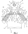
- FIG. 1 shows a transverse cross section
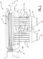
- Figure 3 a longitudinal section of the apparatus.
- the apparatus comprises a first heat transfer zone 10, a second heat transfer zone 20, a downcomer 30, and a closed circuit 5 for cycling (indicated by arrows 5a, 5b, 5c) a heat transfer fluid 9, all arranged in an ambient 100.
- the ambient 100 consists of air.
- the first heat transfer zone 10, the second heat transfer zone 20 and the downcomer 30 all form part of the closed circuit 5.
- the second heat transfer zone 20 may comprise at least one riser tube 22, in which case the heat transfer fluid 9 may be conveyed within the at least one riser tube 22 while the ambient is in contact with the outside of the at least one riser tube 22.
- the first heat transfer zone 10 comprises a first box 13, in the form of a shell, which contains the heat transfer fluid 9.
- the first heat transfer zone 10 comprises a first heat transfer surface 11, which may be arranged within the first box 13.
- the shell of the first box 13 may be an elongated body, for instance in the form of an essentially cylindrical drum, provided with suitable covers on the front and rear ends. Outwardly curved shell covers may be a suitable option.
- the shell stretches longitudinally along a main axis A.
- the first heat transfer surface 11 functions to bring a liquefied stream that is to be heated in a first indirect heat exchanging contact with the heat transfer fluid 9, whereby the heat transfer fluid 9 is located on the opposing side of the first heat exchange surface 11 which is the side of the first heat exchange surface that faces away from the liquefied stream that is to be heated.
- the second heat transfer zone 20 is located gravitationally lower than the first heat transfer zone 10.
- the second heat transfer zone 20 comprises a second heat transfer surface 21, across which the heat transfer fluid 9 is brought in a second indirect heat exchanging contact with the ambient 100.
- the downcomer 30 fluidly connects the first heat transfer zone 10 with the second heat transfer zone 20.
- the downcomer 30 has an upstream end for allowing passage of the heat transfer fluid from the first heat transfer zone 10 into the downcomer 30, and a downstream end for allowing passage of the heat transfer fluid 9 from the downcomer 30 towards the second heat transfer zone 20.
- the downcomer 30 has a transverse portion 34 and a downward portion 36 fluidly connected to each other via a connecting elbow portion 38.
- the connecting elbow portion 38 when viewed in a vertical projection on a horizontal plane, is located external to the first box 13 compared to the main axis A.
- the downward portion 36 of the downcomer 30 can be horizontally displaced (in the projection) from the first box 13. Consequently, the circulation of ambient air (52) in vertical direction needs to be hindered less by the first box 13 in which the first heat transfer zone 10 is housed, because the ambient air can circulate in a vertical direction between the connecting elbow 38 and the first box 13.
- the second heat transfer 21 surface is preferably arranged, at least for a part of the second heat transfer surface 21, in the space between the connecting elbow 38 and the first box 13 when seen in the projection on the horizontal plane.
- the downcomer 30 may take various forms.
- the downcomer may comprise a common section 31 which fluidly connects the first heat transfer zone 10 with a T-junction 23 where the heat transfer fluid 9 is divided over two branches 32.
- a valve 33 for instance in the form of a butterfly valve, may optionally be provided in the downcomer 30 and/or in each of the branches 32 of the downcomer 30. This may be a manually operated valve. With this valve the circulation of the heat transfer fluid through the closed cycle can be trimmed; in case of a large vertical differential in the downcomer 30, there could be substantial effect of the liquid static head on the bubble point (boiling point) which can be counteracted by creating a frictional pressure drop through the valve 33.
- the downcomer 30 runs approximately parallel to the riser tube(s) 22 over the downward portion 36.
- a cross section similar to Fig. 1 of an example of such an alternative embodiment.
- the alternative embodiment has many of the same features as described above.
- One difference to be highlighted is that the flow direction along arrow 5b of the heat transfer fluid 9 in the downward portion 36 of each branch 32 deviates less from vertical than the flow direction along arrow 5c of the heat transfer fluid 9 in the generally straight portion of the riser tubes 22.
- the flow direction along arrow 5b in the downward portion 36 of each branch 32 stretches within about 10° from vertical.
- the second heat transfer surface 21 is arranged predominantly in the space between the connecting elbow 38 and the first box 13 (when seen in the projection on the horizontal plane).
- a first nominal flow direction of the heat transfer fluid 9 from the first heat transfer zone 10 to the second heat transfer zone 20 in the transverse portion 34 may suitably be less vertically directed than a second nominal flow direction of the heat transfer fluid 9 from the first heat transfer zone 10 to the second heat transfer zone 20 in the downward portion 36 (the latter nominal flow direction is indicated by 5b).
- the first nominal flow direction (5a) is deviated within a range of from 60° to 90° from the vertical direction, more preferably within a range of from 80° to 90° from the vertical direction.
- the second nominal flow direction (5b) is deviated within a range of from 0° to 40° from the vertical direction, more preferably within a range of from 0° to 30° from the vertical direction, and most preferably within a range of from 0° to 10° from the vertical direction.
- pressure gradient in a downcomer portion that is orientated this way i.e. vertical or near-vertical down flow
- the pressure gradient in the downcomer is particularly sensitive to presence of vapour within this inclination range, whereby the two-phase flow regime is stratified wavy.
- the sensitivity of the circulation of the heat exchange fluid 9 through the closed circuit to the presence of vapour in the downcomer is surprisingly sensitive at angles of inclination in the range of between 30° and 60°
- the transverse portion 34 By arranging the transverse portion 34 such that the first nominal flow direction (5a) is deviated within a range of from 60° to 90° from the vertical direction, preferably within a range of from 80° to 90° from the vertical direction, and arranging the downward portion 36 such that the second nominal flow direction (5b) is deviated within a range of from 0° to 40°, preferably within a range of from 0° to 30° from the vertical direction, more preferably within a range of from 0° to 10° from the vertical direction, an average flow direction through all portions of the downcomer 30 of within the inclination range of between 30° and 60° can be achieved without the need for the heat transfer fluid 9 to flow through the downcomer 30 at an angle within this inclination range except for a relatively small duration within the connecting elbow portion 38.
- the connecting elbow portion 38 is defined as the part of the downcomer between the transverse portion 34 and the downward portion 36 where the flow direction is at an inclination between 30° and 60°.
- the second heat transfer surface 21 may be located in a generally straight portion of the at least one riser tube 22.
- the heat transfer fluid 9 is cycled along a third nominal flow direction, along arrow 5c, in the generally straight portion of the riser tube 22.
- the third nominal flow direction (indicated at arrow 5c) of the heat transfer fluid 9 inside the generally straight portion may deviate from vertical by an inclination angle that is less than the amount of deviation from the vertical of the first nominal flow direction (5a) and that is more than the amount of deviation from the vertical of the second nominal flow direction (5b).
- the third nominal flow direction (5c) may deviate from vertical by an inclination angle of between 20° and 70°, preferably of between 30° and 60°.
- the generally straight portion of the at least one riser tube 22 may be at any desired angle, including angles corresponding the third nominal flow direction (5c) as specified above.
- the heat transfer fluid 9 is cycled in the direction along arrow 5c in the generally straight portion of the riser tube 22 deviating by an angle of about 30° from vertical.
- the closed circuit 5 may comprise a distribution header 40 to fluidly connect the downcomer 30 and the second heat transfer zone 20 with each other.
- a distribution header 40 may be useful if the second heat transfer zone 20 comprises a plurality of riser tubes 22.
- the at least one riser tube 22, or plurality thereof, is fluidly connected to the first heat transfer zone 10.
- the optional distribution header 40 is preferably arranged gravitationally lower than the second heat transfer zone 40.
- the two branches 32 may be connected to one distribution header 40 each, whereby each of these distribution headers are separate in the sense that the heat transfer fluid 9 inside one of these distribution headers cannot flow to the other except via the T-junction 23 or via the first heat transfer zone 10.
- the T-junction 23 may be located gravitationally below the first box 13.
- the branches 32 may suitably extend transverse to the direction of the main axis A.
- the riser tubes 22 of the plurality of riser tubes may be arranged distributed over the distribution header 40 in a main direction that is parallel to the main axis A.
- each distribution header 40 suitably also has an elongate shape essentially in the same direction as the main axis A, in which case the riser tubes 22 may be suitably configured in a plane that is parallel to the main axis A.
- the riser tubes are arranged over a two-dimensional pattern both in the main direction as well as in a transverse direction extending transversely relative to the main direction.
- the invention also encompasses embodiments wherein the downward portion 36 of each branch of the downcomer 30 is arranged in the same plane as the riser tubes 22.
- the number of riser tubes 22 that fluidly connect a selected distribution header 40 with the first heat transfer zone 10 is larger than the number of downcomers (and/or number of branches of a single downcomer) that fluidly connect the first heat transfer zone 10 with that same distribution header 40.
- the plurality of riser tubes 22 may suitably be arranged divided in two subsets, a first subset being arranged on one side of the downcomer 30 (or branch 32) that connects the distribution header 40 with the first heat transfer zone 10, while a second subset of which is arranged on the other side of the downcomer 30 (or branch 32).
- An air seal 57 may be located between the downcomer 30 (or branch 32) and each of the subsets of riser tubes 22, on either side of the downcomer 30, to avoid that air bypasses the second heat transfer zone though the gap between the downcomer 30 and each of the subsets of riser tubes 22.
- the heat transfer fluid 9 may be conveyed within the one or more riser tubes 22 while the ambient is in contact with the outside of the one or more riser tubes 22.
- the outside surface of the one or more riser tubes 22 may conveniently be provided with heat transfer improvers such as area-enlargers. These may be in the form of fins 29, grooves (not shown) or other suitable means. Please note that fins 29 may be present on all of the riser tubes 22, but for reason of clarity they have only been drawn on one of the riser tubes 22 in Fig. 3 .
- a fan 50 may be positioned relative to the second heat transfer zone 20 to increase circulation of ambient air along the second heat transfer zone 20, as indicated in Figure 1 by arrows 52.
- the heat transfer rate in the second indirect heat exchanging contact may be increased.
- the fan is housed in an air duct 55 arranged to guide the ambient air from the fan 20 to the second heat transfer zone 20 or vice versa.
- the ambient air circulates generally downwardly from the second heat transfer zone 20 into the air duct 55 and to the fan 50.
- the first box 13 may contain a liquid layer 6 of the heat transfer fluid 9 in liquid phase, and a vapour zone 8 above it.
- a nominal liquid level 7 is defined as the level of the interface between liquid layer 6 and the vapour zone 8 during normal operation of the heater.
- the first heat exchange surface 11 is preferably arranged within the vapour zone 8 in the first heat transfer zone 10, above the nominal liquid level 7.
- the first heat transfer surface 11 may suitably be formed out of one or more tubes 12, optionally arranged in a tube bundle 14.
- the liquefied stream that is to be heated may be conveyed within the one or more tubes 12 while the heat transfer fluid is in contact with the outside of the one or more tubes 12.
- the tubes 12 may be arranged single pass or multi pass, with any suitable stationary head on the front end and/or rear end if necessary.
- a two-pass tube bundle 14 in the form of a U-tube bundle.
- the shell cover on the front end 15 of this particular shell is provided with a cover nozzle 16 comprising a head flange 17 to which any type of suitable, preferably stationary, head and tube sheet can be mounted.
- One or more pass partitions may be provided in the head for multi-pass tube bundles.
- a single pass partition suffices for a two-pass tube bundle.
- the invention is not limited to this particular type of cover nozzle 16; for instance a cover nozzle with a fixed tube sheet may be selected, instead.
- a suitable head is an integral bonnet head or a head with removable cover.
- the tubes may be secured in relative position with each other by one or more transverse baffles or support plates.
- a mechanical construction inside the first box 13 may be provided to support the tube bundle, for instance in the form of a structure that is positioned below the tube bundle.
- the tube ends may be secured in the tube sheet.
- the rear end may also be provided with a cover nozzle, so that, instead of the U-tube, a tube sheet may be provided at the rear end as well.
- the interface between the first heat transfer zone 10 and the downcomer 30 may be formed by a through opening in the shell of the first box 13.
- the interface is preferably located gravitationally lower than the nominal liquid level 7 of the heat transfer fluid 9 within the first box 13.
- the second heat transfer zone 20 preferably discharges into the first heat transfer zone 10 at a location that is gravitationally above the nominal liquid level 7. This way the heat transfer fluid 9 can be cycled back from the second heat transfer zone 20 to the first heat transfer zone 10 while bypassing the layer of liquid phase of the heat exchange fluid 9 that has accumulated in the first box 13. This may be accomplished as illustrated in Figures 1 and 2 by riser end pieces 24 fluidly connected to the riser tubes and extending between the riser tubes 22 and a vapour zone 8 inside the first heat transfer zone 10 above the nominal liquid level 7, which riser end pieces 24 traverse the liquid layer 6.
- the open ends of the riser end pieces 24 may be located gravitationally higher than the first heat exchange surface 11, or gravitationally lower than the first heat exchange surface 11.
- one or more liquid diversion means may be provided to shield the riser end pieces 24 from condensed heat exchange fluid 9 falling down from the first heat exchange surface 11 during operation.
- Such liquid diversion means may be embodied in many ways, one of which is illustrated in Figs. 1 and 2 in the form of a weir plate 25 arranged between the first heat exchange surface 11 (e.g. provided on the tubes 12) and the open ends of the riser pieces 24.
- the illustrated weir plate 25 is arranged parallel to main axis A and inclined about 30° from the horizontal to guide the condensed heat transfer fluid 9 towards the longitudinal center of the box 13.
- Other arrangements are possible, such as a vertical arrangement of the weir plates whereby the first heat exchange surfaces are on one side of the vertical plane in which the weir plate is arranged, and the riser end pieces are on the other side of the vertical plane, and/or such as bubble caps on the riser end pieces similar to those used in distillation trays. Combinations of these and/or other ways may also be employed.
- the downcomer 30 may be thermally insulated from the ambient 100. This is schematically shown in Fig. 1 by an insulation layer 35 applied to an external surface of the downcomer 30.
- the insulation layer 35 may be formed of and/or comprise any suitable pipe or duct insulating material and it may optionally be offering protection against under-insulation corrosion.
- the insulation layer comprises a foam material, preferably a closed-cell foam material to avoid percolation condense.
- One example is Armaflex (TM) pipe insulation optionally provided with an Armachek-R (TM) cladding, both commercially obtainable from Armacell UK Ltd. Armachek-R (TM) is a high-density rubber-based cover lining.
- the apparatus is preferably operated such that it comprises a liquid layer 6 of the heat transfer fluid 9 in the liquid phase accumulated within the first heat transfer zone 10. Only liquid from the liquid layer 6 is passed in liquid phase through the downcomer 30 to the second heat transfer zone 20.
- a vortex breaker 60 may be a provided at the upstream end of the downcomer 30, for instance at or near the interface between the first heat transfer zone 10 and the downcomer 30.
- the vortex breaker 60 is suitably near the interface between the first heat transfer zone 10 and the common section 31 of the downcomer 30.
- a vortex breaker is a known device applied to avoid occurrence of a vortex swirl in the liquid layer 6, as this may entrap vapour in the liquid flowing into the downcomer 30.
- the optional distribution header 40 may be thermally insulated from the ambient - for instance in the same way as the downcomer 30.
- the thermal insulation of the distribution header 40 may comprise a layer of an insulating material on the distribution header 40, preferably the same insulating material as used for the downcomer 30.
- the apparatus in operation, is suitable for use in a method of heating a liquefied stream.
- a prime example of a liquefied stream to be heated is an LNG stream.
- the resulting heated stream may be a revaporized natural gas stream (produced by heating and vaporizing liquefied natural gas) may be distributed via a pipe network of a natural gas grid.
- LNG is usually a mixture of primarily methane, together with a relatively low (e.g. less than 25 mol.%) amount of ethane, propane and butanes (C 2 -C 4 ) with trace quantities of heavier hydrocarbons (C 5 +) including pentanes and possibly some non-hydrocarbon components (typically less than 2 mol.%) including for instance nitrogen, water, carbon dioxide, and/or hydrogen disulfide.
- the temperature of LNG is low enough to keep it in liquid phase at a pressure of less than 2 bar absolute.
- Such a mixture can be derived from natural gas.
- a suitable heat transfer fluid for accomplishing the heating of LNG is CO 2 .
- the heat transfer fluid 9 is cycled in the closed circuit 5. During said cycling the heat transfer fluid 9 undergoes a first phase transition from vapour to liquid phase in the first heat transfer zone 10, and second phase transition from liquid to vapour phase in the second heat transfer zone 20.
- the heat transfer fluid comprises at least 90 mol% CO 2 , more preferably it consists for 100 mol% or about 100 mol% of CO 2 .
- An important advantage of CO 2 when used for heating LNG is that - if a leak occurs in the closed circuit 5 for the heat transfer fluid 9 - the CO 2 will solidify at the leakage point thereby reducing or even blocking the leakage point.
- CO 2 doesn't result in flammable mixtures if it would leak from the closed circuit.
- the boiling point of CO 2 is in the range of from -5.8 to -0.1 °C at pressures in the range of from 30 to 35 bar.
- the liquefied stream that is to be heated is passed through the first heat transfer zone 10, in indirect heat exchanging contact with the heat transfer fluid 9, whereby heat is transferred from the heat transfer fluid 9 to the liquefied stream that passes through the first heat transfer zone 10.
- the indirect heat exchanging takes place between the liquefied stream that is to be heated and the vapour of the heat transfer fluid 9 within the in the vapour zone 8.
- the liquefied stream that is to be heated is fed into one or more tubes 12 of the optional tube bundle 14. If the liquefied stream is at high pressure, it may be in a supercritical state wherein no phase transition takes place upon heating. Below the critical pressure, the liquefied stream may stay below its bubble point, or partially or fully vaporize in the one or more tubes 12, as it passes through the first heat transfer zone 10.
- the first heat exchange surface 11 is preferably arranged within the vapour zone 8 in the first heat transfer zone 10, above the nominal liquid level 7.
- the condensed portion of the heat transfer fluid 9 is allowed to accumulate in the first heat transfer zone 10 to form the liquid layer 6 of the heat transfer fluid 9 in the liquid phase.
- the condensed portion may drop from the first heat transfer surface 11, preferably above the nominal liquid level 7, into the liquid layer 6, possibly via the liquid diversion means such as one of the weir plates 25.
- a part of the liquid heat exchange fluid 9 present in the liquid layer 6 flows into the downcomer 30. This forms part of the cycling of the heat transfer fluid 9 in the closed circuit 5.
- the liquid phase flows downward through the downcomer 30, and preferably thermally insulated from the ambient, from the first heat transfer zone 10 via the downcomer 30 to the second heat transfer zone 20, and back to the first heat transfer zone 20.
- the flow rate of the heat transfer fluid through the downcomer 30, or preferably the relative flow rates through each branch 32 of the downcomer 30, is regulated by the valve 33.
- the heat transfer fluid 9 is indirectly heat exchanging with the ambient, whereby heat is passed from the ambient to the heat transfer fluid 9 and the heat transfer fluid 9 is vaporized.
- the optional fan 50 may be utilized to increase circulation of ambient air along the second heat transfer zone 20.
- the ambient air may traverse the second heat transfer zone 20 in a downward direction, as indicated in Figure 1 by the arrows 52.
- the heat transfer fluid 9 preferably rises upward during said vaporizing of the heat transfer fluid 9 in the second heat transfer zone 20. This rising upward may take place in the at least one riser tube 22, preferably in the plurality of riser tubes 22. In the latter case, the condensed portion leaving the downcomer 30 is preferably distributed over the plurality of riser tubes 22.
- vapour is generated and/or present inside the downcomer 30, as any vapour in the downcomer 30 may adversely affect the flow behaviour of the heat transfer fluid 9 inside the closed circuit 5.
- the cycling of the heat transfer fluid 9 through the closed circuit 5 is exclusively driven by gravity, it is advantageous to avoid any vapour in the downcomer 30.
- the condensed portion in liquid phase preferably passes from the first heat transfer zone 10 to the downcomer 30 via the vortex breaker 60, which further helps to avoid access of vapour into the downcomer 30.
Landscapes
- Engineering & Computer Science (AREA)
- Mechanical Engineering (AREA)
- General Engineering & Computer Science (AREA)
- Physics & Mathematics (AREA)
- Thermal Sciences (AREA)
- Life Sciences & Earth Sciences (AREA)
- Sustainable Development (AREA)
- Geometry (AREA)
- Filling Or Discharging Of Gas Storage Vessels (AREA)
Claims (15)
- Appareil pour chauffer un flux liquéfié, comprenant un circuit fermé pour la circulation
cyclique d'un fluide caloporteur (9), le circuit fermé (5) comprenant une première zone de transfert de chaleur (10), une seconde zone de transfert de chaleur (20), et une goulotte de descente (30), toutes étant agencées dans un milieu ambiant (100),
dans lequel la première zone de transfert de chaleur (10) comprend une première boîte (13) sous forme de coque qui contient le fluide caloporteur (9), laquelle première boîte (13) s'étend longitudinalement le long d'un axe principal (A),
dans lequel une première surface de transfert de chaleur (11) est agencée à l'intérieur de la première boîte (13), à travers laquelle première surface de transfert de chaleur (11)
un premier contact d'échange de chaleur indirect est ét abli entre un flux liquéfié à chauffer et le fluide caloporteur (9),
dans lequel la seconde zone de transfert de chaleur (20) est située par gravitation en dessous de la première zone de transfert de chaleur (10) et où la seconde zone de transfert de chaleur (20) comprend une seconde surface de transfert de chaleur (21) à travers laquelle le fluide caloporteur (9) est amené en second contact d'échange de chaleur indirect avec le milieu ambiant (100), et
dans lequel la goulotte de descente (30) relie de manière fluidique la première zone de transfert de chaleur (10) à la seconde zone de transfert de chaleur (20),
caractérisé en ce que la goulotte de descente (30) comprend une première partie transversale (34) et une première partie descendante (36) qui sont reliées de manière fluidique entre elles par l'intermédiaire d'une partie de coude de raccordement (38),
dans lequel la partie de coude de raccordement (38), lorsqu'on l'observe dans une projection verticale sur un plan horizontal, est située à l'extérieur de la première boîte (13) par rapport à l'axe principal (A). - Appareil selon la revendication 1, dans lequel la seconde surface de transfert de chaleur est
agencée, au moins pour une partie de la seconde surface de transfert de chaleur, dans l'espace entre le coude de raccordement et la première boîte lorsqu'on l'observe dans la projection sur le plan horizontal. - Appareil selon la revendication 1 ou 2, dans lequel une première direction d'écoulement nominal du fluide caloporteur de la première zone de transfert de chaleur vers la seconde zone de transfert de chaleur dans la partie transversale de la goulotte de descente est orientée moins verticalement qu'une deuxième direction d'écoulement nominal du fluide caloporteur de la première zone de transfert de chaleur vers la seconde zone de transfert de chaleur dans la partie descendante.
- Appareil selon la revendication 3, dans lequel la seconde zone de transfert de chaleur
comprend au moins un tube montant qui est relié de manière fluidique à la première zone de transfert de chaleur, dans lequel la seconde surface de transfert de chaleur est située dans une partie généralement rectiligne de l'au moins un tube montant, dans laquelle une troisième direction d'écoulement nominal du fluide caloporteur dévie par rapport à la verticale selon un angle d'inclinaison inférieur à la déviation par rapport à la verticale de la première direction d'écoulement nominale et supérieur à la déviation par rapport à la verticale de la deuxième direction d'écoulement nominal. - Appareil selon la revendication 4, dans lequel la troisième direction d'écoulement nominal dévie par rapport à la verticale selon un angle d'inclinaison compris entre 20° et 70°.
- Appareil selon la revendication 4, dans lequel la troisième direction d'écoulement nominal dévie par rapport à la verticale selon un angle d'inclinaison compris entre 30° et 60°.
- Appareil selon l'une quelconque des revendications 3 à 6, dans lequel la première direction d'écoulement nominal, dans la partie transversale de la goulotte de descente, est déviée dans une plage de 60° à 90° par rapport à la direction verticale.
- Appareil selon l'une quelconque des revendications 3 à 6, dans lequel la première direction d'écoulement nominal, dans la partie transversale de la goulotte de descente, est déviée dans une plage de 80° à 90° par rapport à la direction verticale.
- Appareil selon l'une quelconque des revendications 3 à 8, dans lequel la deuxième direction d'écoulement nominal, dans la partie descendante de la goulotte de descente, est déviée dans une plage de 0° à 40° par rapport à la direction verticale.
- Appareil selon l'une quelconque des revendications 3 à 8, dans lequel la deuxième direction d'écoulement nominal, dans la partie descendante de la goulotte de descente, est déviée dans une plage de 0° à 30° par rapport à la direction verticale.
- Appareil selon l'une quelconque des revendications précédentes, dans lequel la goulotte de descente et la seconde zone de transfert de chaleur sont reliées de manière fluidique l'une à l'autre par l'intermédiaire d'un collecteur de distribution, la seconde zone de transfert de chaleur comprenant une pluralité de tubes montants reliant de manière fluidique le collecteur de distribution à la première zone de transfert de chaleur,
dans lequel les tubes montants de la pluralité de tubes montants sont agencés répartis sur le collecteur de distribution dans une direction principale parallèle à l'axe principal. - Appareil selon la revendication 11, dans lequel les tubes montants sont agencés sur un motif bidimensionnel, à la fois dans la direction principale et dans une direction transversale s'étendant
de manière transversale par rapport à la direction principale. - Appareil selon la revendication 11 ou 12, dans lequel, comme vu dans la direction principale, un premier sous-ensemble constitué d'au moins un tube montant de la pluralité de tubes montants est agencé d'un côté de la goulotte de descente qui relie le collecteur de distribution à la première zone de transfert de chaleur, et dans lequel un second sous-ensemble constitué d'au moins un des tubes montants de la pluralité de tubes montants est agencé de l'autre côté de la goulotte de descente.
- Procédé de chauffage d'un flux liquéfié, comprenant- l'utilisation d'un appareil selon l'une quelconque des revendications 1 à 13,- le passage du flux liquéfié à chauffer à travers la première zone de transfert de chaleur de l'appareil, en contact d'échange de chaleur indirect avec le fluide caloporteur, moyennant quoi la chaleur est transférée du fluide caloporteur vers le flux liquéfié, condensant ainsi au moins une partie du fluide caloporteur pour former une partie condensée ;- la circulation cyclique du fluide caloporteur dans le circuit fermé de la première zone de transfert de chaleur par 1' intermédiaire au moins de la goulotte de descente vers la seconde zone de transfert de chaleur et le retour vers la première zone de transfert de chaleur, toutes étant agencées dans un milieu ambiant,dans lequel ladite circulation cyclique du fluide caloporteur comprend le passage de la partie condensée en phase liquide vers le bas à travers la goulotte de descente jusqu'à la seconde zone de transfert de chaleur, et le passage du fluide caloporteur à travers la seconde zone de transfert de chaleur jusqu'à la première zone de transfert de chaleur,
moyennant quoi, dans la seconde zone de transfert de chaleur, un échange de chaleur indirect avec le milieu ambiant permet le passage de la chaleur depuis le milieu ambiant vers le fluide caloporteur et la vaporisation du fluide caloporteur. - Procédé selon la revendication 14, dans lequel le flux liquéfié à chauffer comprend un gaz naturel liquéfié et dans lequel un flux de gaz naturel revaporisé est produit en chauffant et en vaporisant ainsi ledit gaz naturel liquéfié.
Priority Applications (2)
| Application Number | Priority Date | Filing Date | Title |
|---|---|---|---|
| EP13730842.5A EP2867601B1 (fr) | 2012-06-12 | 2013-06-12 | Appareil et procédé pour chauffer un flux liquéfié |
| PL13730842T PL2867601T3 (pl) | 2012-06-12 | 2013-06-12 | Urządzenie i sposób ogrzewania skroplonego strumienia |
Applications Claiming Priority (3)
| Application Number | Priority Date | Filing Date | Title |
|---|---|---|---|
| EP12171677 | 2012-06-12 | ||
| EP13730842.5A EP2867601B1 (fr) | 2012-06-12 | 2013-06-12 | Appareil et procédé pour chauffer un flux liquéfié |
| PCT/EP2013/062183 WO2013186277A1 (fr) | 2012-06-12 | 2013-06-12 | Appareil et procédé de chauffe d'un flux liquéfié |
Publications (2)
| Publication Number | Publication Date |
|---|---|
| EP2867601A1 EP2867601A1 (fr) | 2015-05-06 |
| EP2867601B1 true EP2867601B1 (fr) | 2018-01-10 |
Family
ID=48672589
Family Applications (1)
| Application Number | Title | Priority Date | Filing Date |
|---|---|---|---|
| EP13730842.5A Active EP2867601B1 (fr) | 2012-06-12 | 2013-06-12 | Appareil et procédé pour chauffer un flux liquéfié |
Country Status (9)
| Country | Link |
|---|---|
| US (1) | US9951906B2 (fr) |
| EP (1) | EP2867601B1 (fr) |
| JP (1) | JP6134384B2 (fr) |
| KR (1) | KR102066309B1 (fr) |
| CN (1) | CN104508416B (fr) |
| PH (1) | PH12014502688A1 (fr) |
| PL (1) | PL2867601T3 (fr) |
| TR (1) | TR201802281T4 (fr) |
| WO (1) | WO2013186277A1 (fr) |
Families Citing this family (6)
| Publication number | Priority date | Publication date | Assignee | Title |
|---|---|---|---|---|
| SG10201911907RA (en) | 2015-06-29 | 2020-01-30 | Shell Int Research | Regasification terminal and a method of operating such a regasification terminal |
| EP3184876A1 (fr) | 2015-12-23 | 2017-06-28 | Shell Internationale Research Maatschappij B.V. | Terminal de regazéification de cogénération de gaz naturel liquide |
| WO2018036869A1 (fr) | 2016-08-23 | 2018-03-01 | Shell Internationale Research Maatschappij B.V. | Terminal de regazéification et procédé de fonctionnement d'un tel terminal de regazéification |
| TWI718485B (zh) * | 2019-02-27 | 2021-02-11 | 雙鴻科技股份有限公司 | 熱交換裝置 |
| CN111998705B (zh) * | 2019-05-27 | 2022-03-29 | 山东大学 | 一种旋转对称的循环热源环路热管 |
| CN111998704B (zh) * | 2019-05-27 | 2022-02-01 | 山东大学 | 一种镜像对称的环路热管的振动方法 |
Family Cites Families (64)
| Publication number | Priority date | Publication date | Assignee | Title |
|---|---|---|---|---|
| GB181647A (en) | 1921-10-14 | 1922-06-22 | G & J Weir Ltd | Improvements in steam condensers |
| US1959377A (en) * | 1928-03-20 | 1934-05-22 | Babcock & Wilcox Co | Heat transfer apparatus |
| US2119091A (en) | 1935-11-29 | 1938-05-31 | Standard Oil Dev Co | Process and apparatus for indirect heat transfer between two liquid materials |
| US2273257A (en) | 1940-07-15 | 1942-02-17 | Griscom Russell Co | Evaporation of liquefied gases |
| FR957121A (fr) * | 1941-05-31 | 1950-02-16 | ||
| US2350348A (en) | 1942-12-21 | 1944-06-06 | Gen Motors Corp | Heat transfer device |
| US2499736A (en) | 1946-09-06 | 1950-03-07 | Kleen Nils Erland Af | Aircraft refrigeration |
| US2580547A (en) | 1946-12-27 | 1952-01-01 | Joseph D Hollcrcft | Self-cleaning gas safety tank |
| US2837212A (en) | 1954-02-10 | 1958-06-03 | J A Zurn Mfg Co | Surface drain |
| GB1027719A (fr) | 1963-12-02 | |||
| US3469698A (en) | 1967-04-05 | 1969-09-30 | Josam Mfg Co | Controlled flow drain |
| US3887759A (en) | 1972-11-29 | 1975-06-03 | Gen Electric | Evaporative cooling system employing liquid film evaporation from grooved evaporator surface and vapor push pump for circulating liquid |
| GB1416106A (en) | 1973-10-09 | 1975-12-03 | Black Sivalls & Bryson Inc | Method of vaporizing and combining a liquefied cryogenic fluid stream with a gas stream |
| FR2290629B1 (fr) | 1974-11-05 | 1985-06-14 | Aerazur Constr Aeronaut | Commande electrique de tete de gonflement pour bouteilles de gaz comprime, liquefie ou dissous |
| US4027728A (en) | 1975-03-31 | 1977-06-07 | Mitsubishi Denki Kabushiki Kaisha | Vapor cooling device for semiconductor device |
| US4194536A (en) | 1976-12-09 | 1980-03-25 | Eaton Corporation | Composite tubing product |
| CA1103539A (fr) | 1977-08-19 | 1981-06-23 | Queen's University At Kingston | Heliocapteur a echangeur de chaleur |
| JPS5944556B2 (ja) | 1977-10-14 | 1984-10-30 | 三井造船株式会社 | 液化天然ガス専焼プラントの気化装置 |
| JPS55101710A (en) | 1979-01-25 | 1980-08-04 | Sumitomo Heavy Ind Ltd | Method of vaporizing liquefied natural gas at thermal power plant |
| JPS55165494A (en) * | 1979-06-07 | 1980-12-23 | Babcock Hitachi Kk | Heat exchanger employing heat transfer tube |
| ZA803959B (en) | 1979-07-23 | 1982-04-28 | British Nuclear Fuels Ltd | Apparatus for metering and controlling a feed of hydrogen fluoride vapour |
| FR2477276A1 (fr) | 1980-02-29 | 1981-09-04 | Air Liquide | Procede et installation de rechauffement d'un fluide froid |
| US4485670A (en) | 1981-02-13 | 1984-12-04 | The United States Of America As Represented By The Administrator Of The National Aeronautics And Space Administration | Heat pipe cooled probe |
| GB2097279B (en) | 1981-04-27 | 1984-08-01 | Health Lab Service Board | Affinity chromatography in presence of metal ions |
| JPH0231313B2 (ja) * | 1985-12-02 | 1990-07-12 | Fujikura Densen Kk | Bunrigatahiitopaipushikikukyonetsuki |
| JPS62233687A (ja) * | 1986-04-01 | 1987-10-14 | Yamato Seisakusho:Kk | 熱伝達装置 |
| JPS6376652A (ja) | 1986-09-19 | 1988-04-06 | Fujitsu Ltd | クロツク切替回路 |
| DE3704028A1 (de) | 1986-10-10 | 1988-04-14 | Uhde Gmbh | Verfahren zur herstellung von vinylchlorid durch thermische spaltung von 1,2-dichlorethan |
| JPS6480100A (en) | 1987-09-21 | 1989-03-24 | Hitachi Ltd | Manufacture of multilayered printed circuit board |
| JPH01111197A (ja) | 1987-10-23 | 1989-04-27 | Akutoronikusu Kk | 熱伝達装置 |
| JPH01307600A (ja) * | 1988-06-02 | 1989-12-12 | Tokyo Gas Co Ltd | ヒートパイプを利用した低温液化ガス気化器 |
| JPH01180100U (fr) * | 1988-06-09 | 1989-12-25 | ||
| US4995234A (en) | 1989-10-02 | 1991-02-26 | Chicago Bridge & Iron Technical Services Company | Power generation from LNG |
| JPH0648147B2 (ja) | 1990-03-30 | 1994-06-22 | 東京瓦斯株式会社 | 二重管式オープンラック型気化装置 |
| US5163303A (en) | 1990-03-30 | 1992-11-17 | Tokyo Gas Co. Ltd. | Double-walled tube type open rack evaporating device |
| US5195575A (en) | 1991-04-09 | 1993-03-23 | Roger Wylie | Passive three-phase heat tube for the protection of apparatus from exceeding maximum or minimum safe working temperatures |
| JPH05164482A (ja) | 1991-12-12 | 1993-06-29 | Kobe Steel Ltd | 液化天然ガスの気化装置 |
| US5390500A (en) | 1992-12-29 | 1995-02-21 | Praxair Technology, Inc. | Cryogenic fluid vaporizer system and process |
| US5360056A (en) | 1993-07-28 | 1994-11-01 | Martin Marietta Energy Systems, Inc. | Temperature initiated passive cooling system |
| MY114772A (en) * | 1994-07-05 | 2003-01-31 | Shell Int Research | Apparatus for cooling hot gas |
| DE4431546A1 (de) * | 1994-09-05 | 1996-03-07 | Jakob Dr Ing Hois | Verfahren und Vorrichtung zum Entsalzen von Meerwasser |
| DE19527674C2 (de) | 1995-07-31 | 2000-11-02 | Anceram Gmbh & Co Kg | Kühleinrichtung |
| US6119767A (en) | 1996-01-29 | 2000-09-19 | Denso Corporation | Cooling apparatus using boiling and condensing refrigerant |
| GB2312499B (en) | 1996-03-29 | 2000-10-25 | Denso Corp | Cooling apparatus using boiling and condensing refrigerant |
| GB2317222B (en) | 1996-09-04 | 1998-11-25 | Babcock & Wilcox Co | Heat pipe heat exchangers for subsea pipelines |
| US5937656A (en) | 1997-05-07 | 1999-08-17 | Praxair Technology, Inc. | Nonfreezing heat exchanger |
| US5931156A (en) | 1997-11-18 | 1999-08-03 | Industrial Technology Research Institute | Integral heat-pipe type solar collector |
| US6026889A (en) | 1998-06-18 | 2000-02-22 | Joseph Oat Corporation | Single shell boiler |
| USD425013S (en) | 1998-11-30 | 2000-05-16 | Herman Lai | Solar collector |
| CN2383027Y (zh) | 1999-05-28 | 2000-06-14 | 李百忍 | 无垢热水锅炉外置式换热装置 |
| JP3946398B2 (ja) | 2000-01-18 | 2007-07-18 | 株式会社神戸製鋼所 | 中間媒体式気化器及び当該気化器を用いた天然ガスの供給方法 |
| EP1201298A1 (fr) | 2000-10-24 | 2002-05-02 | Urea Casale S.A. | Dispositif pour la condensation de carbamate |
| US6698212B2 (en) | 2001-07-03 | 2004-03-02 | Thermo King Corporation | Cryogenic temperature control apparatus and method |
| US7155917B2 (en) | 2004-06-15 | 2007-01-02 | Mustang Engineering L.P. (A Wood Group Company) | Apparatus and methods for converting a cryogenic fluid into gas |
| US7311746B2 (en) | 2004-05-21 | 2007-12-25 | Exxonmobil Chemical Patents Inc. | Vapor/liquid separation apparatus for use in cracking hydrocarbon feedstock containing resid |
| US20060242969A1 (en) * | 2005-04-27 | 2006-11-02 | Black & Veatch Corporation | System and method for vaporizing cryogenic liquids using a naturally circulating intermediate refrigerant |
| JP5045056B2 (ja) | 2005-11-04 | 2012-10-10 | 株式会社デンソー | 冷却装置およびその製造方法 |
| PT1855047E (pt) * | 2006-05-12 | 2009-10-09 | Black & Veatch Corp | Sistema e método para vaporizar líquidos criogénicos usando um refrigerante intermediário circulando naturalmente |
| MX2009000686A (es) * | 2006-07-25 | 2009-01-30 | Shell Int Research | Metodo y dispositivo para vaporizar una corriente de liquido. |
| CN101182976A (zh) | 2006-11-14 | 2008-05-21 | 诺亚公司 | 散热腔体及具有散热腔体的相变散热装置 |
| US20080156034A1 (en) | 2006-12-28 | 2008-07-03 | Whirlpool Corporation | Distributed refrigeration system with custom storage modules |
| CN201069316Y (zh) | 2007-07-27 | 2008-06-04 | 白庆华 | 风冷换热器 |
| CN102959346B (zh) | 2010-11-16 | 2015-11-25 | 扎黑德·胡赛恩·阿优伯 | 薄膜蒸发器 |
| US9200850B2 (en) | 2011-07-25 | 2015-12-01 | Tai-Her Yang | Closed-loop temperature equalization device having a heat releasing system structured by multiple flowpaths |
-
2013
- 2013-06-12 KR KR1020147036850A patent/KR102066309B1/ko active IP Right Grant
- 2013-06-12 PL PL13730842T patent/PL2867601T3/pl unknown
- 2013-06-12 WO PCT/EP2013/062183 patent/WO2013186277A1/fr active Application Filing
- 2013-06-12 CN CN201380040476.1A patent/CN104508416B/zh not_active Expired - Fee Related
- 2013-06-12 JP JP2015516607A patent/JP6134384B2/ja not_active Expired - Fee Related
- 2013-06-12 US US14/405,752 patent/US9951906B2/en not_active Expired - Fee Related
- 2013-06-12 TR TR2018/02281T patent/TR201802281T4/tr unknown
- 2013-06-12 EP EP13730842.5A patent/EP2867601B1/fr active Active
-
2014
- 2014-12-02 PH PH12014502688A patent/PH12014502688A1/en unknown
Also Published As
| Publication number | Publication date |
|---|---|
| CN104508416A (zh) | 2015-04-08 |
| JP6134384B2 (ja) | 2017-05-24 |
| US20150121904A1 (en) | 2015-05-07 |
| KR20150020625A (ko) | 2015-02-26 |
| WO2013186277A1 (fr) | 2013-12-19 |
| JP2015522789A (ja) | 2015-08-06 |
| EP2867601A1 (fr) | 2015-05-06 |
| CN104508416B (zh) | 2016-12-14 |
| TR201802281T4 (tr) | 2018-03-21 |
| PH12014502688B1 (en) | 2015-01-26 |
| PH12014502688A1 (en) | 2015-01-26 |
| US9951906B2 (en) | 2018-04-24 |
| PL2867601T3 (pl) | 2018-07-31 |
| KR102066309B1 (ko) | 2020-01-14 |
Similar Documents
| Publication | Publication Date | Title |
|---|---|---|
| EP2867601B1 (fr) | Appareil et procédé pour chauffer un flux liquéfié | |
| US9103498B2 (en) | Method and apparatus for vaporizing a liquid stream | |
| EP2861926B1 (fr) | Appareil et procédé pour chauffer un flux liquéfié | |
| EP2861905B1 (fr) | Appareil et procédé pour chauffer un flux liquéfié | |
| CA2669262C (fr) | Procede et appareil consistant a fournir l'uniformite des phases vapeur et liquide dans un courant melange |
Legal Events
| Date | Code | Title | Description |
|---|---|---|---|
| PUAI | Public reference made under article 153(3) epc to a published international application that has entered the european phase |
Free format text: ORIGINAL CODE: 0009012 |
|
| 17P | Request for examination filed |
Effective date: 20141127 |
|
| AK | Designated contracting states |
Kind code of ref document: A1 Designated state(s): AL AT BE BG CH CY CZ DE DK EE ES FI FR GB GR HR HU IE IS IT LI LT LU LV MC MK MT NL NO PL PT RO RS SE SI SK SM TR |
|
| AX | Request for extension of the european patent |
Extension state: BA ME |
|
| DAX | Request for extension of the european patent (deleted) | ||
| GRAP | Despatch of communication of intention to grant a patent |
Free format text: ORIGINAL CODE: EPIDOSNIGR1 |
|
| INTG | Intention to grant announced |
Effective date: 20170816 |
|
| GRAS | Grant fee paid |
Free format text: ORIGINAL CODE: EPIDOSNIGR3 |
|
| GRAA | (expected) grant |
Free format text: ORIGINAL CODE: 0009210 |
|
| AK | Designated contracting states |
Kind code of ref document: B1 Designated state(s): AL AT BE BG CH CY CZ DE DK EE ES FI FR GB GR HR HU IE IS IT LI LT LU LV MC MK MT NL NO PL PT RO RS SE SI SK SM TR |
|
| REG | Reference to a national code |
Ref country code: CH Ref legal event code: EP Ref country code: AT Ref legal event code: REF Ref document number: 962851 Country of ref document: AT Kind code of ref document: T Effective date: 20180115 |
|
| REG | Reference to a national code |
Ref country code: IE Ref legal event code: FG4D |
|
| REG | Reference to a national code |
Ref country code: DE Ref legal event code: R096 Ref document number: 602013032068 Country of ref document: DE |
|
| REG | Reference to a national code |
Ref country code: NL Ref legal event code: FP |
|
| RAP2 | Party data changed (patent owner data changed or rights of a patent transferred) |
Owner name: SHELL INTERNATIONALE RESEARCH MAATSCHAPPIJ B.V. |
|
| REG | Reference to a national code |
Ref country code: EE Ref legal event code: FG4A Ref document number: E015121 Country of ref document: EE Effective date: 20180215 |
|
| REG | Reference to a national code |
Ref country code: FR Ref legal event code: PLFP Year of fee payment: 6 |
|
| REG | Reference to a national code |
Ref country code: AT Ref legal event code: MK05 Ref document number: 962851 Country of ref document: AT Kind code of ref document: T Effective date: 20180110 |
|
| PG25 | Lapsed in a contracting state [announced via postgrant information from national office to epo] |
Ref country code: LT Free format text: LAPSE BECAUSE OF FAILURE TO SUBMIT A TRANSLATION OF THE DESCRIPTION OR TO PAY THE FEE WITHIN THE PRESCRIBED TIME-LIMIT Effective date: 20180110 Ref country code: HR Free format text: LAPSE BECAUSE OF FAILURE TO SUBMIT A TRANSLATION OF THE DESCRIPTION OR TO PAY THE FEE WITHIN THE PRESCRIBED TIME-LIMIT Effective date: 20180110 Ref country code: ES Free format text: LAPSE BECAUSE OF FAILURE TO SUBMIT A TRANSLATION OF THE DESCRIPTION OR TO PAY THE FEE WITHIN THE PRESCRIBED TIME-LIMIT Effective date: 20180110 Ref country code: FI Free format text: LAPSE BECAUSE OF FAILURE TO SUBMIT A TRANSLATION OF THE DESCRIPTION OR TO PAY THE FEE WITHIN THE PRESCRIBED TIME-LIMIT Effective date: 20180110 Ref country code: NO Free format text: LAPSE BECAUSE OF FAILURE TO SUBMIT A TRANSLATION OF THE DESCRIPTION OR TO PAY THE FEE WITHIN THE PRESCRIBED TIME-LIMIT Effective date: 20180410 Ref country code: CY Free format text: LAPSE BECAUSE OF FAILURE TO SUBMIT A TRANSLATION OF THE DESCRIPTION OR TO PAY THE FEE WITHIN THE PRESCRIBED TIME-LIMIT Effective date: 20180110 |
|
| PG25 | Lapsed in a contracting state [announced via postgrant information from national office to epo] |
Ref country code: LV Free format text: LAPSE BECAUSE OF FAILURE TO SUBMIT A TRANSLATION OF THE DESCRIPTION OR TO PAY THE FEE WITHIN THE PRESCRIBED TIME-LIMIT Effective date: 20180110 Ref country code: SE Free format text: LAPSE BECAUSE OF FAILURE TO SUBMIT A TRANSLATION OF THE DESCRIPTION OR TO PAY THE FEE WITHIN THE PRESCRIBED TIME-LIMIT Effective date: 20180110 Ref country code: IS Free format text: LAPSE BECAUSE OF FAILURE TO SUBMIT A TRANSLATION OF THE DESCRIPTION OR TO PAY THE FEE WITHIN THE PRESCRIBED TIME-LIMIT Effective date: 20180510 Ref country code: RS Free format text: LAPSE BECAUSE OF FAILURE TO SUBMIT A TRANSLATION OF THE DESCRIPTION OR TO PAY THE FEE WITHIN THE PRESCRIBED TIME-LIMIT Effective date: 20180110 Ref country code: AT Free format text: LAPSE BECAUSE OF FAILURE TO SUBMIT A TRANSLATION OF THE DESCRIPTION OR TO PAY THE FEE WITHIN THE PRESCRIBED TIME-LIMIT Effective date: 20180110 Ref country code: BG Free format text: LAPSE BECAUSE OF FAILURE TO SUBMIT A TRANSLATION OF THE DESCRIPTION OR TO PAY THE FEE WITHIN THE PRESCRIBED TIME-LIMIT Effective date: 20180410 |
|
| REG | Reference to a national code |
Ref country code: GR Ref legal event code: EP Ref document number: 20180400912 Country of ref document: GR Effective date: 20180829 |
|
| REG | Reference to a national code |
Ref country code: DE Ref legal event code: R097 Ref document number: 602013032068 Country of ref document: DE |
|
| PG25 | Lapsed in a contracting state [announced via postgrant information from national office to epo] |
Ref country code: IT Free format text: LAPSE BECAUSE OF FAILURE TO SUBMIT A TRANSLATION OF THE DESCRIPTION OR TO PAY THE FEE WITHIN THE PRESCRIBED TIME-LIMIT Effective date: 20180110 Ref country code: AL Free format text: LAPSE BECAUSE OF FAILURE TO SUBMIT A TRANSLATION OF THE DESCRIPTION OR TO PAY THE FEE WITHIN THE PRESCRIBED TIME-LIMIT Effective date: 20180110 Ref country code: RO Free format text: LAPSE BECAUSE OF FAILURE TO SUBMIT A TRANSLATION OF THE DESCRIPTION OR TO PAY THE FEE WITHIN THE PRESCRIBED TIME-LIMIT Effective date: 20180110 |
|
| PLBE | No opposition filed within time limit |
Free format text: ORIGINAL CODE: 0009261 |
|
| STAA | Information on the status of an ep patent application or granted ep patent |
Free format text: STATUS: NO OPPOSITION FILED WITHIN TIME LIMIT |
|
| PG25 | Lapsed in a contracting state [announced via postgrant information from national office to epo] |
Ref country code: SM Free format text: LAPSE BECAUSE OF FAILURE TO SUBMIT A TRANSLATION OF THE DESCRIPTION OR TO PAY THE FEE WITHIN THE PRESCRIBED TIME-LIMIT Effective date: 20180110 Ref country code: DK Free format text: LAPSE BECAUSE OF FAILURE TO SUBMIT A TRANSLATION OF THE DESCRIPTION OR TO PAY THE FEE WITHIN THE PRESCRIBED TIME-LIMIT Effective date: 20180110 Ref country code: CZ Free format text: LAPSE BECAUSE OF FAILURE TO SUBMIT A TRANSLATION OF THE DESCRIPTION OR TO PAY THE FEE WITHIN THE PRESCRIBED TIME-LIMIT Effective date: 20180110 Ref country code: SK Free format text: LAPSE BECAUSE OF FAILURE TO SUBMIT A TRANSLATION OF THE DESCRIPTION OR TO PAY THE FEE WITHIN THE PRESCRIBED TIME-LIMIT Effective date: 20180110 |
|
| 26N | No opposition filed |
Effective date: 20181011 |
|
| REG | Reference to a national code |
Ref country code: CH Ref legal event code: PL |
|
| PG25 | Lapsed in a contracting state [announced via postgrant information from national office to epo] |
Ref country code: SI Free format text: LAPSE BECAUSE OF FAILURE TO SUBMIT A TRANSLATION OF THE DESCRIPTION OR TO PAY THE FEE WITHIN THE PRESCRIBED TIME-LIMIT Effective date: 20180110 |
|
| REG | Reference to a national code |
Ref country code: BE Ref legal event code: MM Effective date: 20180630 |
|
| REG | Reference to a national code |
Ref country code: IE Ref legal event code: MM4A |
|
| PG25 | Lapsed in a contracting state [announced via postgrant information from national office to epo] |
Ref country code: MC Free format text: LAPSE BECAUSE OF FAILURE TO SUBMIT A TRANSLATION OF THE DESCRIPTION OR TO PAY THE FEE WITHIN THE PRESCRIBED TIME-LIMIT Effective date: 20180110 Ref country code: LU Free format text: LAPSE BECAUSE OF NON-PAYMENT OF DUE FEES Effective date: 20180612 |
|
| PG25 | Lapsed in a contracting state [announced via postgrant information from national office to epo] |
Ref country code: CH Free format text: LAPSE BECAUSE OF NON-PAYMENT OF DUE FEES Effective date: 20180630 Ref country code: IE Free format text: LAPSE BECAUSE OF NON-PAYMENT OF DUE FEES Effective date: 20180612 Ref country code: LI Free format text: LAPSE BECAUSE OF NON-PAYMENT OF DUE FEES Effective date: 20180630 |
|
| PG25 | Lapsed in a contracting state [announced via postgrant information from national office to epo] |
Ref country code: BE Free format text: LAPSE BECAUSE OF NON-PAYMENT OF DUE FEES Effective date: 20180630 |
|
| PG25 | Lapsed in a contracting state [announced via postgrant information from national office to epo] |
Ref country code: MT Free format text: LAPSE BECAUSE OF NON-PAYMENT OF DUE FEES Effective date: 20180612 |
|
| PG25 | Lapsed in a contracting state [announced via postgrant information from national office to epo] |
Ref country code: PT Free format text: LAPSE BECAUSE OF FAILURE TO SUBMIT A TRANSLATION OF THE DESCRIPTION OR TO PAY THE FEE WITHIN THE PRESCRIBED TIME-LIMIT Effective date: 20180110 |
|
| PG25 | Lapsed in a contracting state [announced via postgrant information from national office to epo] |
Ref country code: HU Free format text: LAPSE BECAUSE OF FAILURE TO SUBMIT A TRANSLATION OF THE DESCRIPTION OR TO PAY THE FEE WITHIN THE PRESCRIBED TIME-LIMIT; INVALID AB INITIO Effective date: 20130612 Ref country code: MK Free format text: LAPSE BECAUSE OF NON-PAYMENT OF DUE FEES Effective date: 20180110 |
|
| PGFP | Annual fee paid to national office [announced via postgrant information from national office to epo] |
Ref country code: TR Payment date: 20200612 Year of fee payment: 8 Ref country code: EE Payment date: 20200528 Year of fee payment: 8 Ref country code: DE Payment date: 20200602 Year of fee payment: 8 Ref country code: GR Payment date: 20200513 Year of fee payment: 8 Ref country code: FR Payment date: 20200512 Year of fee payment: 8 |
|
| PGFP | Annual fee paid to national office [announced via postgrant information from national office to epo] |
Ref country code: PL Payment date: 20200417 Year of fee payment: 8 Ref country code: NL Payment date: 20200615 Year of fee payment: 8 Ref country code: GB Payment date: 20200603 Year of fee payment: 8 |
|
| REG | Reference to a national code |
Ref country code: DE Ref legal event code: R119 Ref document number: 602013032068 Country of ref document: DE |
|
| REG | Reference to a national code |
Ref country code: EE Ref legal event code: MM4A Ref document number: E015121 Country of ref document: EE Effective date: 20210630 |
|
| REG | Reference to a national code |
Ref country code: NL Ref legal event code: MM Effective date: 20210701 |
|
| GBPC | Gb: european patent ceased through non-payment of renewal fee |
Effective date: 20210612 |
|
| PG25 | Lapsed in a contracting state [announced via postgrant information from national office to epo] |
Ref country code: GB Free format text: LAPSE BECAUSE OF NON-PAYMENT OF DUE FEES Effective date: 20210612 Ref country code: DE Free format text: LAPSE BECAUSE OF NON-PAYMENT OF DUE FEES Effective date: 20220101 |
|
| PG25 | Lapsed in a contracting state [announced via postgrant information from national office to epo] |
Ref country code: NL Free format text: LAPSE BECAUSE OF NON-PAYMENT OF DUE FEES Effective date: 20210701 Ref country code: GR Free format text: LAPSE BECAUSE OF NON-PAYMENT OF DUE FEES Effective date: 20220105 Ref country code: FR Free format text: LAPSE BECAUSE OF NON-PAYMENT OF DUE FEES Effective date: 20210630 Ref country code: EE Free format text: LAPSE BECAUSE OF NON-PAYMENT OF DUE FEES Effective date: 20210630 |
|
| PG25 | Lapsed in a contracting state [announced via postgrant information from national office to epo] |
Ref country code: PL Free format text: LAPSE BECAUSE OF NON-PAYMENT OF DUE FEES Effective date: 20210612 |