EP2859272B1 - Combined high energy igniter and flame detector and process for simultaneous ignition and flame detection - Google Patents
Combined high energy igniter and flame detector and process for simultaneous ignition and flame detection Download PDFInfo
- Publication number
- EP2859272B1 EP2859272B1 EP13800648.1A EP13800648A EP2859272B1 EP 2859272 B1 EP2859272 B1 EP 2859272B1 EP 13800648 A EP13800648 A EP 13800648A EP 2859272 B1 EP2859272 B1 EP 2859272B1
- Authority
- EP
- European Patent Office
- Prior art keywords
- electrode
- flame
- spark
- potential
- fuel
- Prior art date
- Legal status (The legal status is an assumption and is not a legal conclusion. Google has not performed a legal analysis and makes no representation as to the accuracy of the status listed.)
- Active
Links
Images


Classifications
-
- F—MECHANICAL ENGINEERING; LIGHTING; HEATING; WEAPONS; BLASTING
- F23—COMBUSTION APPARATUS; COMBUSTION PROCESSES
- F23Q—IGNITION; EXTINGUISHING-DEVICES
- F23Q9/00—Pilot flame igniters
- F23Q9/08—Pilot flame igniters with interlock with main fuel supply
- F23Q9/12—Pilot flame igniters with interlock with main fuel supply to permit the supply to the main burner in dependence upon existence of pilot flame
- F23Q9/14—Pilot flame igniters with interlock with main fuel supply to permit the supply to the main burner in dependence upon existence of pilot flame using electric means, e.g. by light-sensitive elements
-
- F—MECHANICAL ENGINEERING; LIGHTING; HEATING; WEAPONS; BLASTING
- F23—COMBUSTION APPARATUS; COMBUSTION PROCESSES
- F23N—REGULATING OR CONTROLLING COMBUSTION
- F23N5/00—Systems for controlling combustion
- F23N5/02—Systems for controlling combustion using devices responsive to thermal changes or to thermal expansion of a medium
- F23N5/12—Systems for controlling combustion using devices responsive to thermal changes or to thermal expansion of a medium using ionisation-sensitive elements, i.e. flame rods
- F23N5/123—Systems for controlling combustion using devices responsive to thermal changes or to thermal expansion of a medium using ionisation-sensitive elements, i.e. flame rods using electronic means
-
- F—MECHANICAL ENGINEERING; LIGHTING; HEATING; WEAPONS; BLASTING
- F23—COMBUSTION APPARATUS; COMBUSTION PROCESSES
- F23N—REGULATING OR CONTROLLING COMBUSTION
- F23N5/00—Systems for controlling combustion
- F23N5/24—Preventing development of abnormal or undesired conditions, i.e. safety arrangements
-
- F—MECHANICAL ENGINEERING; LIGHTING; HEATING; WEAPONS; BLASTING
- F23—COMBUSTION APPARATUS; COMBUSTION PROCESSES
- F23Q—IGNITION; EXTINGUISHING-DEVICES
- F23Q3/00—Igniters using electrically-produced sparks
-
- F—MECHANICAL ENGINEERING; LIGHTING; HEATING; WEAPONS; BLASTING
- F23—COMBUSTION APPARATUS; COMBUSTION PROCESSES
- F23Q—IGNITION; EXTINGUISHING-DEVICES
- F23Q3/00—Igniters using electrically-produced sparks
- F23Q3/008—Structurally associated with fluid-fuel burners
-
- F—MECHANICAL ENGINEERING; LIGHTING; HEATING; WEAPONS; BLASTING
- F23—COMBUSTION APPARATUS; COMBUSTION PROCESSES
- F23D—BURNERS
- F23D2207/00—Ignition devices associated with burner
-
- F—MECHANICAL ENGINEERING; LIGHTING; HEATING; WEAPONS; BLASTING
- F23—COMBUSTION APPARATUS; COMBUSTION PROCESSES
- F23D—BURNERS
- F23D2208/00—Control devices associated with burners
- F23D2208/10—Sensing devices
-
- F—MECHANICAL ENGINEERING; LIGHTING; HEATING; WEAPONS; BLASTING
- F23—COMBUSTION APPARATUS; COMBUSTION PROCESSES
- F23N—REGULATING OR CONTROLLING COMBUSTION
- F23N2227/00—Ignition or checking
- F23N2227/22—Pilot burners
-
- F—MECHANICAL ENGINEERING; LIGHTING; HEATING; WEAPONS; BLASTING
- F23—COMBUSTION APPARATUS; COMBUSTION PROCESSES
- F23N—REGULATING OR CONTROLLING COMBUSTION
- F23N2227/00—Ignition or checking
- F23N2227/36—Spark ignition, e.g. by means of a high voltage
-
- F—MECHANICAL ENGINEERING; LIGHTING; HEATING; WEAPONS; BLASTING
- F23—COMBUSTION APPARATUS; COMBUSTION PROCESSES
- F23N—REGULATING OR CONTROLLING COMBUSTION
- F23N2229/00—Flame sensors
- F23N2229/02—Pilot flame sensors
Definitions
- This invention pertains to ignition and sensing systems and more particularly to flame ignition and flame detecting or sensing systems. Even more particularly, the invention pertains to such systems having a spark type ignition.
- a gas pilot burner is a device used to create a stable pilot flame by combustion of a low flow rate (relative to the main burner) gaseous fuel-air mixture.
- the pilot flame is used to light a larger main burner, or a difficult to light fuel.
- Gas pilot designs normally include an ignition system and a flame detection system.
- the two most common types of ignition systems used in gas pilot burners are high tension (HT) and high-energy ignition (HEI).
- Flame detection is typically by a flame ionization detection (FID) system.
- An HT flame ignition system typically utilizes a high voltage source and an HT spark plug or spark rod.
- the high voltage source provides high voltage, low current pulses. Often, such pulses will be 15kV or greater and from about 10 to about 50 mA.
- HT systems create low amperage sparks that bridge an air gap created in a spark plug or between a spark rod and the grounded pilot frame. This spark is used to ignite the fuel-air mixture and, thus, generate the pilot flame. While this type of ignition can be low cost, it can be inconsistent when ignition conditions are not ideal. Moisture from steam or rain, contamination and heavy fuel can all generate ignition problems when using an HT system.
- HT or HEI systems allowing for simultaneous ignition and flame detection have relied on using completely separate ignition and detection systems. It would be beneficial to have a powerful ignition system, such as an HEI system, and a flame detection system that can operate simultaneously through the entire window where the flame detection system is an integral part of the HEI systems; that is, without utilizing completely separate ignition and detection systems.
- DE 200 11 457 U1 discloses a laboratory gas burner with a burner head comprising a burner tube, an ignition electrode and a monitor electrode, a gas supply valve and a controller. Also, means for opening and closing the gas supply valve and means for applying a starting voltage to the ignition electrode are disclosed. Further, means for inputting operator commands and means for register a conductivity between the monitor electrode and the burner tube or other counter electrode queries are shown, wherein said control means for registering a conductivity ness for monitoring a gas flame interrogates after the means for opening and closing the gas supply valve is opened and the means for applying the ignition voltage are applied to the ignition of the gas flame, the ignition voltage to the ignition electrode.
- DE 23 36 693 A1 discloses a radiant heating pipe having a disc burner in its air feed pipe, with a central bore through which the gas feed pipe extends in to the flame space; air passage openings are around the central bore.
- An igniter and flame monitor has a voltage-supplying electrode and an earthed counter-electrode; the fast electrode is eccentrically outside the gas feed pipe.
- the counter-electrode is carried by the burner, which is earthed.
- the first electrode runs through the air feed pipe and through the burner, with insulation between. Satisfactory monitoring and long life are obtained with arbitrarily adjusted flame.
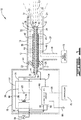
- Pilot burner 10 has a housing 12. Housing 12 is comprised of a main pipe or tube portion 14, electronics enclosure 16 and fuel introduction pipe 18. Tube portion 14 has a wall 20 having a first end 22 and a second end 24 and a longitudinal fuel flow passage or fuel channel 26 defined by wall 20. First end 22 is connected to electronics enclosure 16 and the wall 20 defines an opening 28 at second end 24. At or near first end 22 will be a sealing device 30 which seals fuel channel 26 so that it is not in fluid flow communication with electronics enclosure 16 and, hence, so that fuel cannot enter electronics enclosure 16.
- Fuel introduction pipe 18 is in fluid flow communication with a fuel source 19 and longitudinal fuel flow passage 26 of tube portion 14. Generally, a fuel-air mixture will be introduced into passage 26 through pipe 18 such that the fuel-air mixture will flow in a generally longitudinal direction towards second end 24 and out opening 28.
- Spark rod 31 Extending longitudinally along longitudinal passage 26 is a spark rod 31.
- Spark rod 31 has a first end 32 extending into electronics enclosure 16 and a second end 33 located near the second end of tube portion 14.
- Spark rod 31 is comprised of a center electrode 34, an insulating sleeve or tube 37 and an outer shell or electrode tube 40.
- Center electrode 34 has a first end 35 located within electronics enclosure 16 and a second end 36 located near, but spaced away from, second end 24 of tube portion 14 so that it is inside tube portion 14.
- Electrode tube 40 has a first end 41 located within electronics enclosure 16 and a second end 42 located near, but spaced away from, second end 24 of tube portion 14 so that it is inside tube portion 14.
- Insulating sleeve 37 has a first end 38 located within electronics enclosure 16 and a second end 39 located near second end 24 of tube portion 14 and, as shown, just short of the second ends of center electrode 34 and electrode tube 40 so as to form a well 54. Second ends of center electrode 34, insulating sleeve 37 and electrode tube 40 form spark tip 43 of spark rod 31 (as best seen in FIGS. 2 and 3 ). It should be understood that while spark rod 31 is illustrated as having a center electrode covered by a concentric insulating sleeve and a concentric electrode tube, it could have any other suitable design. Generally, spark rod 31 will have a first electrode and a second electrode that are electrically isolated from each other but with ends that are adapted to transmit a spark from one electrode to the other upon application of an electrical charge on the opposite ends of the electrodes.
- spark rod 31 extends through a second insulating sleeve 44 that isolates spark rod 31 from housing 12, which is connected to ground wire 29 so that housing 12 is at ground potential.
- spark rod 31 is held in place by second insulating sleeve 44.
- spark rod 31 can be attached to second insulating sleeve 44, it is preferred that they be slidingly engaged so that spark rod 31 can be removed from second insulating sleeve 44 at either first end 32 or second end 33.
- Second insulating sleeve 44 is held in place by sealing device 30 and structural supports 46, which are connected to second insulating sleeve 44.
- structural supports 46 can be made from insulating material and connected directly to spark rod 31 without use of second insulating sleeve 44; however, this can hamper removal of spark rod 31 from first end 32 and/or second end 33.
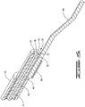
- spark rod 31 has a flame rod 48 attached to electrode tube 40.
- Flame rod 48 is a conducting material that extends towards wall 20 of housing 12 but is not in contact with housing 12. Additionally, flame rod 48 is positioned such that when spark rod 31 has ignited the fuel-air mixture to produce a flame 50, flame rod 48 will be located within the flame.
- spark rod 31 is a high-energy igniter (HEI) probe. Accordingly, spark rod 31 should be suitable to pass large current pulses (often greater than 1kA) from an energy source, further described below, to the spark tip and, thereby, generate a spark at the spark tip.
- the purpose of an HEI probe is to provide high ignition power. In applications with low temperatures, heavy fuels (heavy gases or oils), contamination of the igniter plug with coking or other debris, or moisture presence due to steam purging or rain, the main fuel may be difficult to light but an HEI system has the ability to maintain powerful high energy sparks in these adverse conditions.
- the HEI igniter probe is generally constructed using a center electrode 34, an insulation system (typically comprising insulation sleeve or tube 37) and outer shell or electrode tube 40.
- Outer electrode tube 40 is generally about 0.25 to 0.75 inches in diameter.
- electrode tube 40 has been grounded and not isolated from the pilot frame or housing 12; however, it is an advantage of the current invention that electrode tube 40 not be grounded and be isolated from the housing and, hence, from ground, as is further described herein.
- a semiconductor material 52 can be applied to the insulation tube at the end of the tip to form a conductive path between the center electrode 34 and the electrode tube 40.
- This semiconductor is normally a pellet type piece placed at the end of the insulation tip or a film applied to the insulator itself. This semiconductor assists the HEI probe with spark initiation by allowing a low level of current to pass in the semiconductor when the energy source applies an ignition pulse to the center electrode 34.
- This low level current flowing through the semiconductor creates a small ionized air zone above the path of current in the well 54 of spark rod 31.
- This small ionized air path is a low impedance pathway for current flow. Once the pathway is established, the electrical energy is able to flow unresisted except for circuit impedance, thereby creating a very high current and energy spark at well 54.
- electronics enclosure 16 it has at least partially located therein a source of electrical energy, which includes a power supply 56, exciter 58 and flame detection circuit 60.
- Power supply 56 (as shown located outside of electronics enclosure 16) provides electrical power to both exciter 58 and flame detection circuit 60.
- a controller 62 sometimes referred to as a burner management system (BMS), is operationally connected to the source of electrical energy.
- BMS burner management system
- Exciter 58 can be any high-energy exciter known in the art and suitable to provide a rapid electrical pulse to spark rod 31 and, thus, cause a spark at spark tip 43. Accordingly, exciter 58 will typically be a capacitive discharge device.
- exciter 58 has a transforming element 64, diode 66 and capacitor 68. Terminals 70 and 72 are in electrical connection with capacitor 68. Additionally, terminal 70 is connected to center electrode 34 at first end 35 and terminal 72 is connected to electrode tube 40 at first end 41. Terminal 72 is also connected to terminal 74 of flame detection circuit 60.
- switch 76 Electrical input to exciter 58 can by controlled by switch 76, which is operationally connected to controller 62 (connections not shown). Accordingly, when controller 62 activates switch 76, transforming element 64 steps up the incoming voltage and diode 66 rectifies it such that capacitor 68 is charged by the step up transformer. When a predetermined threshold voltage is reached, switch 78 is closed by the exciter's controller (not shown). This causes the spark gap, between center electrode 34 and electrode tube 40 at spark tip 43, to connect to the potential deference stored on the capacitor 68 and create an arc.
- capacitor 68 energy in capacitor 68 flows through terminal 70 (in this case the high potential terminal) through center electrode 34, across well 54 (spark gap), through electrode tube 40 and terminal 72 (in this case the low potential terminal) and back to the capacitor 68.
- This large capacitive current results in a powerful spark across well 54.
- terminal 70 has a high potential and terminal 72 has a low potential with low potential terminal 72 having an electrical potential below the potential of high potential terminal 70 but above ground potential. This is achieved through galvanic isolation in the transforming element 64 and by electrical connection to terminal 74 of flame detection circuit 60.
- flame detection circuit 60 is supplied power by power supply 56 through terminals 80 and 82. Flame detection circuit 60 is connected to ground wire 84 and is connected to low potential terminal 72 and electrode tube 40 through terminal 74. As mentioned above, terminal 70, electrode 34, terminal 72 and electrode tube 40 are all isolated from ground. Tube portion 14, however, is grounded. Accordingly, when flame detection circuit 60 is activated, there is potential across the gap 51 between flame rod 48 and tube portion 14. As explained below, only when a flame is present and extends between flame rod 48 and tube portion 14, will there be a conductive pathway between flame rod 48 and tube portion 14. However this pathway only conducts current from flame rod 48 to tube portion 14; hence, if the current applied is an alternating current, only a rectified current is passed, similar to that illustrated in FIG. 7 .
- Flame detection circuit 60 provides a signal 86 to controller 62.
- Controller 62 is operationally connected to switch 76, flame detection circuit 60 and the fuel source 19 such that, based upon signals 86 received from flame detection circuit 60, controller 62 can start or stop either the exciter 58 or the fuel-air mixture flowing into pipe 18 or both, as further explained below.
- tube portion 14 comprises wall 20 and hood 21.
- Hood 21 can have air holes 88 located near the second end 33 of spark rod 31 to provide additional air to the flame once the fuel has been ignited.
- Spark rod 31 is seated inside second insulating sleeve 44.
- the insulating sleeve 44 is held in position concentrically or off center to tube portion 14 by sealing device 30 and structural support 46.
- Second end 36 of center electrode 34 and second end 42 of electrode tube 40 extend slightly beyond second end 39 of insulating sleeve 37 so as to form well 54; thus, the second ends form spark tip 43.
- Flame rod 48 is welded or otherwise conductively affixed to the exposed end 89 of electrode tube 40.
- the flame rod 48 is bent in an elongated Z configuration in order to place it near hood 21 of wall 20 but not in contact with and a suitable distance from wall 20 so that there is no electrical conduction between flame rod 48 and wall 20 unless a flame is present.
- a scythe or curved shape configuration may be used.
- the flame rod can be constructed of any suitable conductive material so long as it is isolated from housing 12 and is positioned to be in the flame, after ignition has occurred, such that rectified current flow can occur, as further explained below.
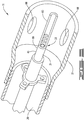
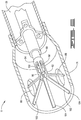
- FIGS. 5 and 6 illustrate other embodiments using different flame rod configurations.
- flame rod 90 is formed by a portion of electrode tube 40, which extends out from the exposed end 89 of electrode tube 40 and from second end 33 of spark rod 31.
- Flame rod 90 has a cross section that is a partial circle, generally a half circle or C-shaped cross section, such that at least a portion of the second end 33 is exposed to the fuel-air mixture passing through longitudinal passage 26 so that the spark occurring at second end 33 can ignite the fuel-air mixture.
- Flame rod 90 is designed to fit within the outer diameter of electrode tube 40 and, hence, within the inner diameter of second insulating sleeve 44.
- flame rod 90 does not extend radially outward from the electrode tube farther than the outer radius of the electrode tube. Accordingly, flame rod 90 allows spark rod 31 to slide through second insulating sleeve 44 so that it can be replaced from the first end 22 of tube portion 14; thus, improving the ease of replacement of spark rod 31. Because flame rod 90 extends longitudinally downstream from spark rod 31 and not radially outward, it can be advantageous for the spark rod to be located off-center of the tube portion 14 so that flame rod 90 is near to wall 20 and better able to establish electrical flow when flame is established.
- flame rod 92 has a first ring portion 94 that slides over and makes conductive contact with the exposed end 89 of electrode tube 40.
- Flame rod 92 has a second ring portion 96 and struts 98 extending between first ring portion 94 and second ring portion 96 to create apertures 100.
- Apertures 100 expose the second end 33 of spark rod 31 to the fuel-air mixture passing through longitudinal passage 26 such that the spark occurring at second end 33 can ignite the fuel-air mixture.
- Extending from second ring portion 96 are flame rod fingers 102. Fingers 102 can extend radially outwardly from second ring portion 96 or at an angle so that they extend radially and longitudinally outwardly from second ring portion 96.
- the tips 104 of fingers 102 should be located near but isolated from wall 20 so that they are not in contact with hood 21 of wall 20 and are a suitable distance so that there is no electrical conduction between flame rod 92 and wall 20, unless a flame is present.
- the tips 104 should be positioned to be in the flame, after ignition has occurred, such that rectified current flow can occur, as further explained below.
- First ring portion 94 can be fixedly attached to the exposed end 89 of electrode tube 40 or can be slidingly engaged onto the exposed end 89. If slidingly engaged onto the exposed end 89 then flame rod 92 can be removed to allow spark rod 31 to slide through second insulating sleeve 44 so that it can be replaced from the first end 22 of tube portion 14; thus improving the ease of replacement of spark rod 31.
- fuel and air are introduced into longitudinal passage 26.
- the fuel and air may be introduced from a fuel-air mixture source 19 into fuel introduction pipe 18 or may each be introduced from separate sources into fuel introduction pipe 18.
- Fuel introduction pipe 18 is in fluid flow communication with longitudinal passage 26 and the fuel and air in pipe 18 is under positive pressure so that fuel and air within pipe 18 flows into longitudinal passage 26.
- Structural supports 46 can be perforated and can be shaped into swirling or diffusion elements to induce premixing of fuel and air within longitudinal passage 26 and prior to reaching the second end 33 of spark rod 31.
- the air and fuel should be adequately mixed upon reaching the second end 33 of spark rod 31 to produce a flame upon exposure to a spark from spark tip 43.
- flame detection circuit 60 Prior to spark initiation, flame detection circuit 60 is powered up. Terminal 74 of flame detection circuit 60 is connected to potential terminal 72 of exciter 58 and electrode tube 40, thus supplying a small current potential to both. While this current can be direct current or alternating current, the operation will be described with respect to alternating current, except where indicated. Spark is initiated by closing switch 76; thus providing power to exciter 58. Center electrode 34 is connected to terminal 70 of exciter 58 and, as previously indicated, electrode tube 40 is connected to the terminal 72 of exciter 58 and flame detection circuit 60. Accordingly, in the embodiment of FIG.
- terminal 70, terminal 72, center electrode 34 and electrode tube 40 are isolated from ground, they are maintained at a higher potential than ground; however, when switch 78 is closed, there is a high potential difference between terminal 70 and terminal 72. This high potential difference is what creates the spark at spark tip 43.
- an electrical pulse will jump between electrode 34 to electrode tube 40 at the spark tip 43 of spark rod 31; preferably, the current will follow the ionized path created by the semiconductor 52.
- This electrical pulse will be in the form of a spark and can ignite the fuel-air mixture around second end 33 of spark rod 31.
- a flame produces free ions in the vicinity of the flame envelope that form an electrically conductive pathway.
- a small current will result (less than 10 ⁇ A). If one of the electrodes is much larger than the other, current will flow more easily from the small electrode to the large electrode than vice-versa.
- a current rectifying property will result and a current will flow across the gap between the two electrodes similar to the rectified current illustrated in FIG. 7 . Detection of this rectification can be used to prove the presence of a flame.
- tube portion 14 is electrically grounded and serves as a third electrode.
- Flame rod 48 is designed to be much smaller than tube portion 14 and, when no flame is present, is electrically isolated from tube portion 14 of the housing 12, and hence from ground. Accordingly, if no flame is present, then no current will flow from flame rod 48 to tube portion 14. If the spark generated at second end 33 of spark rod 31 creates a flame, flame rod 48 is positioned to be in the flame. In other words, the flame rod 48 is positioned so that the flame 50 will bridge the gap 51 so that spark rod 31 is no longer electrically isolated from tube portion 14 and a rectified current (similar to that illustrated in FIG. 7 ) is established that flows from flame rod 48 to tube portion 14.
- Detection circuit 60 sends a signal to controller 62 based on the establishment of a current between flame rod 48 and tube portion 14. When a rectified current is established, detection circuit 60 sends a signal to controller 62. In response to the signal, controller 62 opens switch 76 to shutdown exciter 58 and, hence, stop spark rod 31 from generating sparks. If controller 62 does not receive the signal that a rectified current is established within a predetermined period of time (the timeout period), then controller 62 will shutdown exciter 58 and stop fuel introduction into pipe 18. Additionally, in the case of a short or ground failure, an alternating current can be established between flame rod 48 and tube portion 14, similar to the current illustrated in FIG. 8 .
- detection circuit 60 If detection circuit 60 detects an alternating current flow between flame rod 48 and tube portion 14, it sends a signal to controller 62 and controller 62 will shutdown exciter 58 and stop fuel introduction into pipe 18. While a direct current can be used for flame detection, it will not allow the detecting of a short or ground failure in the manner of an alternating current.
- an inventive integrated high energy ignition (HEI) and flame ionization detection (FID) device operates as follows:
- the current invention has the advantage of being capable of simultaneous rapid ignition and flame detection utilizing an integrated ignition and flame detection system.
- simultaneous refers generally to flame detection during the period that the exciter is energized and the spark rod is sparking.
- the ignition attempt sparking of the spark rod
- the flame detector is energized to detect flame. If no flame is detected, the flame detector is de-energized and the exciter re-energized to initiate another spark.
Landscapes
- Engineering & Computer Science (AREA)
- Chemical & Material Sciences (AREA)
- Combustion & Propulsion (AREA)
- Mechanical Engineering (AREA)
- General Engineering & Computer Science (AREA)
- Control Of Combustion (AREA)
- Other Investigation Or Analysis Of Materials By Electrical Means (AREA)
Applications Claiming Priority (2)
| Application Number | Priority Date | Filing Date | Title |
|---|---|---|---|
| US13/491,250 US9546788B2 (en) | 2012-06-07 | 2012-06-07 | Combined high energy igniter and flame detector |
| PCT/US2013/044535 WO2013184928A1 (en) | 2012-06-07 | 2013-06-06 | Combined high energy igniter and flame detector |
Publications (3)
| Publication Number | Publication Date |
|---|---|
| EP2859272A1 EP2859272A1 (en) | 2015-04-15 |
| EP2859272A4 EP2859272A4 (en) | 2015-12-30 |
| EP2859272B1 true EP2859272B1 (en) | 2020-03-04 |
Family
ID=49712635
Family Applications (1)
| Application Number | Title | Priority Date | Filing Date |
|---|---|---|---|
| EP13800648.1A Active EP2859272B1 (en) | 2012-06-07 | 2013-06-06 | Combined high energy igniter and flame detector and process for simultaneous ignition and flame detection |
Country Status (8)
| Country | Link |
|---|---|
| US (2) | US9546788B2 (enExample) |
| EP (1) | EP2859272B1 (enExample) |
| JP (1) | JP6009661B2 (enExample) |
| KR (1) | KR101675238B1 (enExample) |
| CN (1) | CN104822991B (enExample) |
| CA (1) | CA2875678C (enExample) |
| SG (1) | SG11201408148RA (enExample) |
| WO (1) | WO2013184928A1 (enExample) |
Families Citing this family (25)
| Publication number | Priority date | Publication date | Assignee | Title |
|---|---|---|---|---|
| PL2265867T3 (pl) * | 2008-03-07 | 2019-04-30 | Bertelli & Partners Srl | Ulepszony sposób i urządzenie do wykrywania płomienia w palniku działającym na paliwie stałym, płynnym lub gazowym |
| US9285120B2 (en) * | 2012-10-06 | 2016-03-15 | Coorstek, Inc. | Igniter shield device and methods associated therewith |
| US11317761B2 (en) * | 2013-05-02 | 2022-05-03 | Original Pellet Grill Company Llc | Double-sealed high-temperature resistant DC ignitor for use with wood pellet burner assemblies |
| CN104048688B (zh) * | 2014-06-10 | 2016-08-24 | 陕西航空电气有限责任公司 | 新型离子火焰探测器绝缘体组件 |
| US10101028B2 (en) * | 2015-01-18 | 2018-10-16 | Profire Energy, Inc. | Inline pilot with flame detection device and method thereof |
| US9863635B2 (en) * | 2015-06-24 | 2018-01-09 | General Electric Technology Gmbh | Combined ignitor spark and flame rod |
| CN105910715B (zh) * | 2016-05-24 | 2023-04-18 | 上海莱帝科技有限公司 | 一种明火检测火焰探测器性能的测试装置 |
| US9913359B1 (en) * | 2016-08-17 | 2018-03-06 | General Electric Company | Krypton-85-free spark gap with cantilevered component |
| EP3333482B1 (en) | 2016-12-06 | 2019-09-25 | Honeywell Technologies Sarl | Gas burner controller adapter, gas burner appliance having such a gas burner controller adapter and method for operating such a gas burner appliance |
| KR102019163B1 (ko) * | 2017-10-31 | 2019-09-09 | 린나이코리아 주식회사 | 가스기구의 점화장치에 의해 발생하는 노이즈 유입 방지 장치 |
| CN208154536U (zh) * | 2018-04-10 | 2018-11-27 | 深圳驭龙电器有限公司 | 电加热装置 |
| KR102116036B1 (ko) * | 2018-07-05 | 2020-05-27 | 한국기계연구원 | 글라이딩 아크 점화기 |
| JP7119711B2 (ja) * | 2018-07-27 | 2022-08-17 | 株式会社ノーリツ | 燃焼装置および温水装置 |
| EP3617598B1 (de) * | 2018-08-28 | 2021-04-07 | Paul Rauschert Steinbach GmbH | Verstärkte brennerelektrode |
| KR102121667B1 (ko) * | 2018-09-28 | 2020-06-10 | (주)고려엔지니어링 | 로드 타입 초기 점화 장치 |
| EP3640540B1 (en) | 2018-10-16 | 2021-04-21 | Orkli, S. Coop. | Cooking appliance |
| GB2582744B (en) | 2019-03-26 | 2023-08-23 | John Zink Co Llc | A flame detection and ignition device |
| CN110594784A (zh) * | 2019-10-21 | 2019-12-20 | 江苏天瑞仪器股份有限公司 | 一种氢火焰离子化检测器用点火丝装置及其制备方法 |
| KR102307934B1 (ko) * | 2019-10-29 | 2021-09-30 | 주식회사 포스코 | 열처리로의 점화장치 |
| KR102244774B1 (ko) * | 2019-10-29 | 2021-04-27 | 린나이코리아 주식회사 | 가스레인지용 점화 및 화염검출 제어장치 |
| US11619385B2 (en) | 2020-02-21 | 2023-04-04 | Hearth Products Controls Co. | Ignition system |
| CN111578309A (zh) * | 2020-06-20 | 2020-08-25 | 吴佳璇 | 一种新型锅炉点火枪及其加工方法 |
| US20220302683A1 (en) * | 2021-03-18 | 2022-09-22 | Saudi Arabian Oil Company | Spark system for igniters |
| US12455077B2 (en) | 2022-02-04 | 2025-10-28 | Travis Industries, Inc. | Gas-burning fire installation with an igniter control system |
| US20240230591A1 (en) * | 2023-01-05 | 2024-07-11 | Matthew Monagle | Flame ionization detector ignition aid |
Family Cites Families (55)
| Publication number | Priority date | Publication date | Assignee | Title |
|---|---|---|---|---|
| US2684115A (en) * | 1949-07-09 | 1954-07-20 | Gen Controls Co | Fuel burner safety control using flame conduction |
| US3343366A (en) * | 1958-11-25 | 1967-09-26 | North American Aviation Inc | Spark discharge monitoring device |
| US3136353A (en) | 1962-03-01 | 1964-06-09 | Combustion Eng | Burner means including flame rod detector with internal electric heating |
| US3245457A (en) * | 1962-11-07 | 1966-04-12 | Hunter | Method of igniting liquid fuel |
| US3727073A (en) * | 1970-02-27 | 1973-04-10 | Electronics Corp America | Flame sensor control circuit |
| DE2336693A1 (de) | 1973-07-19 | 1975-02-06 | Nassheuer Ind Ofenbau Jean | Strahlheizrohr |
| US4325690A (en) | 1979-09-17 | 1982-04-20 | Johnson Controls, Inc. | Gas pilot assembly for universal application and method of making same |
| JPS56146925A (en) * | 1980-04-16 | 1981-11-14 | Hitachi Ltd | Ignition and flame detector |
| US4413303A (en) * | 1980-07-05 | 1983-11-01 | Dunlop Limited | Ignition systems |
| GB2087117B (en) * | 1980-11-06 | 1984-06-20 | British Gas Corp | Burner safety system |
| US4391582A (en) * | 1981-03-30 | 1983-07-05 | Cowan Frederick C | Fuel nozzle with concentric ignitor |
| US4402663A (en) * | 1981-04-28 | 1983-09-06 | Ram Products, Inc. | Automatic ignition and flame detection system for gas fired devices |
| US4405299A (en) * | 1981-07-24 | 1983-09-20 | Honeywell Inc. | Burner ignition and flame monitoring system |
| US4466789A (en) | 1981-11-04 | 1984-08-21 | Robertshaw Controls Company | Igniter/flame sensor assembly for gas burner |
| US4527125A (en) * | 1981-11-13 | 1985-07-02 | Hitachi, Ltd. | Flame detecting apparatus |
| GB2127952A (en) * | 1982-09-29 | 1984-04-18 | British Gas Corp | Burner assembly |
| US4457692A (en) * | 1983-08-22 | 1984-07-03 | Honeywell Inc. | Dual firing rate flame sensing system |
| US4534728A (en) * | 1984-04-02 | 1985-08-13 | Honeywell Inc. | Combination gas enricher, spark igniter, flame sensor |
| GB2159267B (en) * | 1984-05-23 | 1987-12-16 | Shell Int Research | Burner with ignition device |
| JPS61180834A (ja) | 1985-02-07 | 1986-08-13 | Mitsubishi Heavy Ind Ltd | 点火用バ−ナの点火・火炎検出装置 |
| US4595354A (en) * | 1985-06-11 | 1986-06-17 | Guerra Romeo E | Igniter for gas discharge pipe with a flame detection system |
| US4724823A (en) * | 1986-09-29 | 1988-02-16 | Solaronics, Inc. | Radiant gas burner assembly |
| JPH07117241B2 (ja) | 1990-02-26 | 1995-12-18 | 東京瓦斯株式会社 | バーナの燃焼安全機構 |
| US5472336A (en) * | 1993-05-28 | 1995-12-05 | Honeywell Inc. | Flame rectification sensor employing pulsed excitation |
| US5577905A (en) * | 1994-11-16 | 1996-11-26 | Robertshaw Controls Company | Fuel control system, parts therefor and methods of making and operating the same |
| US5617721A (en) | 1995-08-14 | 1997-04-08 | General Motors Corporation | Exhaust catalyst preheater with flame igniter and sensor element |
| US5655900A (en) * | 1995-11-20 | 1997-08-12 | Harper-Wyman Company | Gas oven control system |
| US5777216A (en) * | 1996-02-01 | 1998-07-07 | Adrenaline Research, Inc. | Ignition system with ionization detection |
| US5779465A (en) | 1996-09-06 | 1998-07-14 | Clarke; Beresford N. | Spark ignited burner |
| US5865616A (en) * | 1996-12-12 | 1999-02-02 | Wayne/Scott Fetzer Company | Premix gas burner |
| US5741129A (en) * | 1996-12-23 | 1998-04-21 | Ranco Incorporated Of Delaware | Igniting and sensing flame on a fuel gas burner |
| US6059562A (en) * | 1998-08-13 | 2000-05-09 | Bethlehem Steel Corporation | Gas appliance with automatic gas shut-off device responsive to flame outage |
| US6222719B1 (en) | 1999-07-15 | 2001-04-24 | Andrew S. Kadah | Ignition boost and rectification flame detection circuit |
| US6509838B1 (en) * | 2000-02-08 | 2003-01-21 | Peter P. Payne | Constant current flame ionization circuit |
| DE20011457U1 (de) | 2000-06-29 | 2000-12-07 | Wartewig, Andrea, 37085 Göttingen | Laborgasbrenner mit einem Brennerkopf und Einrichtungen zum Überwachen des Brennerkopfs |
| US6729873B2 (en) * | 2001-06-20 | 2004-05-04 | W. C. Bradley Company | Automatic flame-out detector and reignition system and method of ignition |
| US6794771B2 (en) * | 2002-06-20 | 2004-09-21 | Ranco Incorporated Of Delaware | Fault-tolerant multi-point flame sense circuit |
| JP3925647B2 (ja) | 2003-01-20 | 2007-06-06 | トヨタ自動車株式会社 | 燃焼装置 |
| CA2481536A1 (en) | 2004-09-14 | 2006-03-14 | Acl Manufacturing Inc. | Burner assembly |
| US7241135B2 (en) | 2004-11-18 | 2007-07-10 | Honeywell International Inc. | Feedback control for modulating gas burner |
| US7492269B2 (en) | 2005-02-24 | 2009-02-17 | Alstom Technology Ltd | Self diagonostic flame ignitor |
| US8085521B2 (en) * | 2007-07-03 | 2011-12-27 | Honeywell International Inc. | Flame rod drive signal generator and system |
| US8066508B2 (en) * | 2005-05-12 | 2011-11-29 | Honeywell International Inc. | Adaptive spark ignition and flame sensing signal generation system |
| US7764182B2 (en) * | 2005-05-12 | 2010-07-27 | Honeywell International Inc. | Flame sensing system |
| US20060286495A1 (en) * | 2005-06-21 | 2006-12-21 | Roussel Paul D | Ignition and flame supervision system for open flame gas lights |
| US20070224558A1 (en) * | 2006-03-08 | 2007-09-27 | American Flame, Inc. | Gas flow and combustion control system |
| US7479006B2 (en) * | 2006-08-02 | 2009-01-20 | General Electric Company | Apparatus and methods for operating a cooking appliance |
| JP2008177142A (ja) * | 2006-12-19 | 2008-07-31 | Denso Corp | プラズマ式点火装置 |
| US7927095B1 (en) * | 2007-09-30 | 2011-04-19 | The United States Of America As Represented By The United States Department Of Energy | Time varying voltage combustion control and diagnostics sensor |
| US20090181334A1 (en) | 2008-01-10 | 2009-07-16 | Derek Moore | Burner ignition control system |
| CN201187792Y (zh) * | 2008-03-11 | 2009-01-28 | 黄紹忠 | 一种新型电子点火与检测装置 |
| CN101871656A (zh) * | 2009-04-24 | 2010-10-27 | 西安拓沃能动科技有限公司 | 全预混全自动点火烧嘴 |
| US10132770B2 (en) * | 2009-05-15 | 2018-11-20 | A. O. Smith Corporation | Flame rod analysis system |
| US20110086319A1 (en) * | 2009-07-15 | 2011-04-14 | Saint-Gobain Ceramics & Plastics, Inc. | Fuel gas ignition system for gas burners including devices and methods related thereto |
| US20120288806A1 (en) * | 2011-05-10 | 2012-11-15 | International Controls And Measurements Corporation | Flame Sense Circuit for Gas Pilot Control |
-
2012
- 2012-06-07 US US13/491,250 patent/US9546788B2/en active Active
-
2013
- 2013-06-06 KR KR1020157000119A patent/KR101675238B1/ko active Active
- 2013-06-06 CN CN201380038295.5A patent/CN104822991B/zh active Active
- 2013-06-06 EP EP13800648.1A patent/EP2859272B1/en active Active
- 2013-06-06 CA CA2875678A patent/CA2875678C/en active Active
- 2013-06-06 SG SG11201408148RA patent/SG11201408148RA/en unknown
- 2013-06-06 WO PCT/US2013/044535 patent/WO2013184928A1/en not_active Ceased
- 2013-06-06 JP JP2015516213A patent/JP6009661B2/ja active Active
-
2016
- 2016-10-17 US US15/294,847 patent/US9822978B2/en active Active
Non-Patent Citations (1)
| Title |
|---|
| None * |
Also Published As
| Publication number | Publication date |
|---|---|
| CN104822991A (zh) | 2015-08-05 |
| KR20150068349A (ko) | 2015-06-19 |
| US9822978B2 (en) | 2017-11-21 |
| US20170038071A1 (en) | 2017-02-09 |
| SG11201408148RA (en) | 2015-01-29 |
| WO2013184928A1 (en) | 2013-12-12 |
| EP2859272A1 (en) | 2015-04-15 |
| US9546788B2 (en) | 2017-01-17 |
| JP2015522788A (ja) | 2015-08-06 |
| CA2875678C (en) | 2017-01-17 |
| CN104822991B (zh) | 2017-08-25 |
| EP2859272A4 (en) | 2015-12-30 |
| KR101675238B1 (ko) | 2016-11-10 |
| US20130330675A1 (en) | 2013-12-12 |
| JP6009661B2 (ja) | 2016-10-19 |
| CA2875678A1 (en) | 2013-12-12 |
Similar Documents
| Publication | Publication Date | Title |
|---|---|---|
| EP2859272B1 (en) | Combined high energy igniter and flame detector and process for simultaneous ignition and flame detection | |
| JP2015522788A5 (enExample) | ||
| RU2620916C2 (ru) | Устройство нагрева воды и способ для измерения силы тока пламени в пламени в устройстве нагрева воды | |
| US4710125A (en) | Safety device for oil burner | |
| US9863635B2 (en) | Combined ignitor spark and flame rod | |
| US20230055175A1 (en) | Spark Ignition Pilot Assembly | |
| US9482431B2 (en) | Radially firing igniter | |
| RU85608U1 (ru) | Устройство зажигания и контроля пламени | |
| RU106340U1 (ru) | Запально-защитное устройство | |
| JPS62272017A (ja) | 燃焼器の点火および火炎検知装置 | |
| US20210199290A1 (en) | Cooking appliance | |
| RU53411U1 (ru) | Запальное устройство | |
| KR20220137362A (ko) | 파일럿 버너 | |
| KR20220137363A (ko) | 파일럿 버너 | |
| JP2022056081A (ja) | 点火動作検査装置 | |
| JPH0525159U (ja) | 燃焼器の点火および火炎検知装置 | |
| KR19990019015U (ko) | 화염감지봉과 일체화된 보일러의 점화플러그 |
Legal Events
| Date | Code | Title | Description |
|---|---|---|---|
| PUAI | Public reference made under article 153(3) epc to a published international application that has entered the european phase |
Free format text: ORIGINAL CODE: 0009012 |
|
| 17P | Request for examination filed |
Effective date: 20141217 |
|
| AK | Designated contracting states |
Kind code of ref document: A1 Designated state(s): AL AT BE BG CH CY CZ DE DK EE ES FI FR GB GR HR HU IE IS IT LI LT LU LV MC MK MT NL NO PL PT RO RS SE SI SK SM TR |
|
| AX | Request for extension of the european patent |
Extension state: BA ME |
|
| DAX | Request for extension of the european patent (deleted) | ||
| RA4 | Supplementary search report drawn up and despatched (corrected) |
Effective date: 20151127 |
|
| RIC1 | Information provided on ipc code assigned before grant |
Ipc: F23N 3/00 20060101AFI20151123BHEP Ipc: F24C 3/00 20060101ALI20151123BHEP |
|
| STAA | Information on the status of an ep patent application or granted ep patent |
Free format text: STATUS: EXAMINATION IS IN PROGRESS |
|
| 17Q | First examination report despatched |
Effective date: 20171027 |
|
| GRAP | Despatch of communication of intention to grant a patent |
Free format text: ORIGINAL CODE: EPIDOSNIGR1 |
|
| STAA | Information on the status of an ep patent application or granted ep patent |
Free format text: STATUS: GRANT OF PATENT IS INTENDED |
|
| INTG | Intention to grant announced |
Effective date: 20190920 |
|
| GRAS | Grant fee paid |
Free format text: ORIGINAL CODE: EPIDOSNIGR3 |
|
| GRAA | (expected) grant |
Free format text: ORIGINAL CODE: 0009210 |
|
| STAA | Information on the status of an ep patent application or granted ep patent |
Free format text: STATUS: THE PATENT HAS BEEN GRANTED |
|
| AK | Designated contracting states |
Kind code of ref document: B1 Designated state(s): AL AT BE BG CH CY CZ DE DK EE ES FI FR GB GR HR HU IE IS IT LI LT LU LV MC MK MT NL NO PL PT RO RS SE SI SK SM TR |
|
| REG | Reference to a national code |
Ref country code: GB Ref legal event code: FG4D |
|
| REG | Reference to a national code |
Ref country code: CH Ref legal event code: EP |
|
| REG | Reference to a national code |
Ref country code: AT Ref legal event code: REF Ref document number: 1240804 Country of ref document: AT Kind code of ref document: T Effective date: 20200315 |
|
| REG | Reference to a national code |
Ref country code: DE Ref legal event code: R096 Ref document number: 602013066502 Country of ref document: DE |
|
| REG | Reference to a national code |
Ref country code: IE Ref legal event code: FG4D |
|
| REG | Reference to a national code |
Ref country code: NL Ref legal event code: FP |
|
| PG25 | Lapsed in a contracting state [announced via postgrant information from national office to epo] |
Ref country code: FI Free format text: LAPSE BECAUSE OF FAILURE TO SUBMIT A TRANSLATION OF THE DESCRIPTION OR TO PAY THE FEE WITHIN THE PRESCRIBED TIME-LIMIT Effective date: 20200304 Ref country code: RS Free format text: LAPSE BECAUSE OF FAILURE TO SUBMIT A TRANSLATION OF THE DESCRIPTION OR TO PAY THE FEE WITHIN THE PRESCRIBED TIME-LIMIT Effective date: 20200304 Ref country code: NO Free format text: LAPSE BECAUSE OF FAILURE TO SUBMIT A TRANSLATION OF THE DESCRIPTION OR TO PAY THE FEE WITHIN THE PRESCRIBED TIME-LIMIT Effective date: 20200604 |
|
| PG25 | Lapsed in a contracting state [announced via postgrant information from national office to epo] |
Ref country code: HR Free format text: LAPSE BECAUSE OF FAILURE TO SUBMIT A TRANSLATION OF THE DESCRIPTION OR TO PAY THE FEE WITHIN THE PRESCRIBED TIME-LIMIT Effective date: 20200304 Ref country code: BG Free format text: LAPSE BECAUSE OF FAILURE TO SUBMIT A TRANSLATION OF THE DESCRIPTION OR TO PAY THE FEE WITHIN THE PRESCRIBED TIME-LIMIT Effective date: 20200604 Ref country code: LV Free format text: LAPSE BECAUSE OF FAILURE TO SUBMIT A TRANSLATION OF THE DESCRIPTION OR TO PAY THE FEE WITHIN THE PRESCRIBED TIME-LIMIT Effective date: 20200304 Ref country code: SE Free format text: LAPSE BECAUSE OF FAILURE TO SUBMIT A TRANSLATION OF THE DESCRIPTION OR TO PAY THE FEE WITHIN THE PRESCRIBED TIME-LIMIT Effective date: 20200304 Ref country code: GR Free format text: LAPSE BECAUSE OF FAILURE TO SUBMIT A TRANSLATION OF THE DESCRIPTION OR TO PAY THE FEE WITHIN THE PRESCRIBED TIME-LIMIT Effective date: 20200605 |
|
| REG | Reference to a national code |
Ref country code: LT Ref legal event code: MG4D |
|
| PG25 | Lapsed in a contracting state [announced via postgrant information from national office to epo] |
Ref country code: CZ Free format text: LAPSE BECAUSE OF FAILURE TO SUBMIT A TRANSLATION OF THE DESCRIPTION OR TO PAY THE FEE WITHIN THE PRESCRIBED TIME-LIMIT Effective date: 20200304 Ref country code: RO Free format text: LAPSE BECAUSE OF FAILURE TO SUBMIT A TRANSLATION OF THE DESCRIPTION OR TO PAY THE FEE WITHIN THE PRESCRIBED TIME-LIMIT Effective date: 20200304 Ref country code: IS Free format text: LAPSE BECAUSE OF FAILURE TO SUBMIT A TRANSLATION OF THE DESCRIPTION OR TO PAY THE FEE WITHIN THE PRESCRIBED TIME-LIMIT Effective date: 20200704 Ref country code: SK Free format text: LAPSE BECAUSE OF FAILURE TO SUBMIT A TRANSLATION OF THE DESCRIPTION OR TO PAY THE FEE WITHIN THE PRESCRIBED TIME-LIMIT Effective date: 20200304 Ref country code: ES Free format text: LAPSE BECAUSE OF FAILURE TO SUBMIT A TRANSLATION OF THE DESCRIPTION OR TO PAY THE FEE WITHIN THE PRESCRIBED TIME-LIMIT Effective date: 20200304 Ref country code: LT Free format text: LAPSE BECAUSE OF FAILURE TO SUBMIT A TRANSLATION OF THE DESCRIPTION OR TO PAY THE FEE WITHIN THE PRESCRIBED TIME-LIMIT Effective date: 20200304 Ref country code: EE Free format text: LAPSE BECAUSE OF FAILURE TO SUBMIT A TRANSLATION OF THE DESCRIPTION OR TO PAY THE FEE WITHIN THE PRESCRIBED TIME-LIMIT Effective date: 20200304 Ref country code: PT Free format text: LAPSE BECAUSE OF FAILURE TO SUBMIT A TRANSLATION OF THE DESCRIPTION OR TO PAY THE FEE WITHIN THE PRESCRIBED TIME-LIMIT Effective date: 20200729 Ref country code: SM Free format text: LAPSE BECAUSE OF FAILURE TO SUBMIT A TRANSLATION OF THE DESCRIPTION OR TO PAY THE FEE WITHIN THE PRESCRIBED TIME-LIMIT Effective date: 20200304 |
|
| REG | Reference to a national code |
Ref country code: AT Ref legal event code: MK05 Ref document number: 1240804 Country of ref document: AT Kind code of ref document: T Effective date: 20200304 |
|
| REG | Reference to a national code |
Ref country code: DE Ref legal event code: R097 Ref document number: 602013066502 Country of ref document: DE |
|
| PLBE | No opposition filed within time limit |
Free format text: ORIGINAL CODE: 0009261 |
|
| STAA | Information on the status of an ep patent application or granted ep patent |
Free format text: STATUS: NO OPPOSITION FILED WITHIN TIME LIMIT |
|
| PG25 | Lapsed in a contracting state [announced via postgrant information from national office to epo] |
Ref country code: DK Free format text: LAPSE BECAUSE OF FAILURE TO SUBMIT A TRANSLATION OF THE DESCRIPTION OR TO PAY THE FEE WITHIN THE PRESCRIBED TIME-LIMIT Effective date: 20200304 Ref country code: MC Free format text: LAPSE BECAUSE OF FAILURE TO SUBMIT A TRANSLATION OF THE DESCRIPTION OR TO PAY THE FEE WITHIN THE PRESCRIBED TIME-LIMIT Effective date: 20200304 Ref country code: AT Free format text: LAPSE BECAUSE OF FAILURE TO SUBMIT A TRANSLATION OF THE DESCRIPTION OR TO PAY THE FEE WITHIN THE PRESCRIBED TIME-LIMIT Effective date: 20200304 |
|
| REG | Reference to a national code |
Ref country code: CH Ref legal event code: PL |
|
| 26N | No opposition filed |
Effective date: 20201207 |
|
| PG25 | Lapsed in a contracting state [announced via postgrant information from national office to epo] |
Ref country code: PL Free format text: LAPSE BECAUSE OF FAILURE TO SUBMIT A TRANSLATION OF THE DESCRIPTION OR TO PAY THE FEE WITHIN THE PRESCRIBED TIME-LIMIT Effective date: 20200304 Ref country code: SI Free format text: LAPSE BECAUSE OF FAILURE TO SUBMIT A TRANSLATION OF THE DESCRIPTION OR TO PAY THE FEE WITHIN THE PRESCRIBED TIME-LIMIT Effective date: 20200304 |
|
| REG | Reference to a national code |
Ref country code: BE Ref legal event code: MM Effective date: 20200630 |
|
| PG25 | Lapsed in a contracting state [announced via postgrant information from national office to epo] |
Ref country code: IE Free format text: LAPSE BECAUSE OF NON-PAYMENT OF DUE FEES Effective date: 20200606 Ref country code: LI Free format text: LAPSE BECAUSE OF NON-PAYMENT OF DUE FEES Effective date: 20200630 Ref country code: CH Free format text: LAPSE BECAUSE OF NON-PAYMENT OF DUE FEES Effective date: 20200630 |
|
| PG25 | Lapsed in a contracting state [announced via postgrant information from national office to epo] |
Ref country code: BE Free format text: LAPSE BECAUSE OF NON-PAYMENT OF DUE FEES Effective date: 20200630 |
|
| PG25 | Lapsed in a contracting state [announced via postgrant information from national office to epo] |
Ref country code: TR Free format text: LAPSE BECAUSE OF FAILURE TO SUBMIT A TRANSLATION OF THE DESCRIPTION OR TO PAY THE FEE WITHIN THE PRESCRIBED TIME-LIMIT Effective date: 20200304 Ref country code: MT Free format text: LAPSE BECAUSE OF FAILURE TO SUBMIT A TRANSLATION OF THE DESCRIPTION OR TO PAY THE FEE WITHIN THE PRESCRIBED TIME-LIMIT Effective date: 20200304 Ref country code: CY Free format text: LAPSE BECAUSE OF FAILURE TO SUBMIT A TRANSLATION OF THE DESCRIPTION OR TO PAY THE FEE WITHIN THE PRESCRIBED TIME-LIMIT Effective date: 20200304 |
|
| PG25 | Lapsed in a contracting state [announced via postgrant information from national office to epo] |
Ref country code: MK Free format text: LAPSE BECAUSE OF FAILURE TO SUBMIT A TRANSLATION OF THE DESCRIPTION OR TO PAY THE FEE WITHIN THE PRESCRIBED TIME-LIMIT Effective date: 20200304 Ref country code: AL Free format text: LAPSE BECAUSE OF FAILURE TO SUBMIT A TRANSLATION OF THE DESCRIPTION OR TO PAY THE FEE WITHIN THE PRESCRIBED TIME-LIMIT Effective date: 20200304 |
|
| REG | Reference to a national code |
Ref country code: FR Ref legal event code: PLFP Year of fee payment: 11 |
|
| P01 | Opt-out of the competence of the unified patent court (upc) registered |
Effective date: 20230528 |
|
| PGFP | Annual fee paid to national office [announced via postgrant information from national office to epo] |
Ref country code: NL Payment date: 20250409 Year of fee payment: 13 |
|
| PGFP | Annual fee paid to national office [announced via postgrant information from national office to epo] |
Ref country code: DE Payment date: 20250402 Year of fee payment: 13 |
|
| PGFP | Annual fee paid to national office [announced via postgrant information from national office to epo] |
Ref country code: GB Payment date: 20250401 Year of fee payment: 13 |
|
| PGFP | Annual fee paid to national office [announced via postgrant information from national office to epo] |
Ref country code: LU Payment date: 20250530 Year of fee payment: 13 Ref country code: IT Payment date: 20250522 Year of fee payment: 13 |
|
| PGFP | Annual fee paid to national office [announced via postgrant information from national office to epo] |
Ref country code: FR Payment date: 20250401 Year of fee payment: 13 |