EP2859263B1 - Tieftemperatur - leitungskupplung - Google Patents
Tieftemperatur - leitungskupplung Download PDFInfo
- Publication number
- EP2859263B1 EP2859263B1 EP13729290.0A EP13729290A EP2859263B1 EP 2859263 B1 EP2859263 B1 EP 2859263B1 EP 13729290 A EP13729290 A EP 13729290A EP 2859263 B1 EP2859263 B1 EP 2859263B1
- Authority
- EP
- European Patent Office
- Prior art keywords
- coupling
- valve
- housing
- conduit
- coupling half
- Prior art date
- Legal status (The legal status is an assumption and is not a legal conclusion. Google has not performed a legal analysis and makes no representation as to the accuracy of the status listed.)
- Active
Links
Images
Classifications
-
- F—MECHANICAL ENGINEERING; LIGHTING; HEATING; WEAPONS; BLASTING
- F16—ENGINEERING ELEMENTS AND UNITS; GENERAL MEASURES FOR PRODUCING AND MAINTAINING EFFECTIVE FUNCTIONING OF MACHINES OR INSTALLATIONS; THERMAL INSULATION IN GENERAL
- F16L—PIPES; JOINTS OR FITTINGS FOR PIPES; SUPPORTS FOR PIPES, CABLES OR PROTECTIVE TUBING; MEANS FOR THERMAL INSULATION IN GENERAL
- F16L39/00—Joints or fittings for double-walled or multi-channel pipes or pipe assemblies
- F16L39/04—Joints or fittings for double-walled or multi-channel pipes or pipe assemblies allowing adjustment or movement
-
- F—MECHANICAL ENGINEERING; LIGHTING; HEATING; WEAPONS; BLASTING
- F16—ENGINEERING ELEMENTS AND UNITS; GENERAL MEASURES FOR PRODUCING AND MAINTAINING EFFECTIVE FUNCTIONING OF MACHINES OR INSTALLATIONS; THERMAL INSULATION IN GENERAL
- F16J—PISTONS; CYLINDERS; SEALINGS
- F16J15/00—Sealings
-
- F—MECHANICAL ENGINEERING; LIGHTING; HEATING; WEAPONS; BLASTING
- F16—ENGINEERING ELEMENTS AND UNITS; GENERAL MEASURES FOR PRODUCING AND MAINTAINING EFFECTIVE FUNCTIONING OF MACHINES OR INSTALLATIONS; THERMAL INSULATION IN GENERAL
- F16L—PIPES; JOINTS OR FITTINGS FOR PIPES; SUPPORTS FOR PIPES, CABLES OR PROTECTIVE TUBING; MEANS FOR THERMAL INSULATION IN GENERAL
- F16L17/00—Joints with packing adapted to sealing by fluid pressure
- F16L17/02—Joints with packing adapted to sealing by fluid pressure with sealing rings arranged between outer surface of pipe and inner surface of sleeve or socket
- F16L17/025—Joints with packing adapted to sealing by fluid pressure with sealing rings arranged between outer surface of pipe and inner surface of sleeve or socket the sealing rings having radially directed ribs
-
- F—MECHANICAL ENGINEERING; LIGHTING; HEATING; WEAPONS; BLASTING
- F16—ENGINEERING ELEMENTS AND UNITS; GENERAL MEASURES FOR PRODUCING AND MAINTAINING EFFECTIVE FUNCTIONING OF MACHINES OR INSTALLATIONS; THERMAL INSULATION IN GENERAL
- F16L—PIPES; JOINTS OR FITTINGS FOR PIPES; SUPPORTS FOR PIPES, CABLES OR PROTECTIVE TUBING; MEANS FOR THERMAL INSULATION IN GENERAL
- F16L25/00—Construction or details of pipe joints not provided for in, or of interest apart from, groups F16L13/00 - F16L23/00
- F16L25/06—Construction or details of pipe joints not provided for in, or of interest apart from, groups F16L13/00 - F16L23/00 comprising radial locking means
-
- F—MECHANICAL ENGINEERING; LIGHTING; HEATING; WEAPONS; BLASTING
- F16—ENGINEERING ELEMENTS AND UNITS; GENERAL MEASURES FOR PRODUCING AND MAINTAINING EFFECTIVE FUNCTIONING OF MACHINES OR INSTALLATIONS; THERMAL INSULATION IN GENERAL
- F16L—PIPES; JOINTS OR FITTINGS FOR PIPES; SUPPORTS FOR PIPES, CABLES OR PROTECTIVE TUBING; MEANS FOR THERMAL INSULATION IN GENERAL
- F16L29/00—Joints with fluid cut-off means
- F16L29/04—Joints with fluid cut-off means with a cut-off device in each of the two pipe ends, the cut-off devices being automatically opened when the coupling is applied
-
- F—MECHANICAL ENGINEERING; LIGHTING; HEATING; WEAPONS; BLASTING
- F16—ENGINEERING ELEMENTS AND UNITS; GENERAL MEASURES FOR PRODUCING AND MAINTAINING EFFECTIVE FUNCTIONING OF MACHINES OR INSTALLATIONS; THERMAL INSULATION IN GENERAL
- F16L—PIPES; JOINTS OR FITTINGS FOR PIPES; SUPPORTS FOR PIPES, CABLES OR PROTECTIVE TUBING; MEANS FOR THERMAL INSULATION IN GENERAL
- F16L37/00—Couplings of the quick-acting type
- F16L37/28—Couplings of the quick-acting type with fluid cut-off means
- F16L37/30—Couplings of the quick-acting type with fluid cut-off means with fluid cut-off means in each of two pipe-end fittings
-
- Y—GENERAL TAGGING OF NEW TECHNOLOGICAL DEVELOPMENTS; GENERAL TAGGING OF CROSS-SECTIONAL TECHNOLOGIES SPANNING OVER SEVERAL SECTIONS OF THE IPC; TECHNICAL SUBJECTS COVERED BY FORMER USPC CROSS-REFERENCE ART COLLECTIONS [XRACs] AND DIGESTS
- Y10—TECHNICAL SUBJECTS COVERED BY FORMER USPC
- Y10T—TECHNICAL SUBJECTS COVERED BY FORMER US CLASSIFICATION
- Y10T137/00—Fluid handling
- Y10T137/8593—Systems
- Y10T137/87917—Flow path with serial valves and/or closures
- Y10T137/87925—Separable flow path section, valve or closure in each
- Y10T137/87941—Each valve and/or closure operated by coupling motion
- Y10T137/87949—Linear motion of flow path sections operates both
Definitions
- the invention relates to a line coupling for connecting a first line to a second line for the purpose of passing low-temperature media.
- Suitable media include in particular liquefied natural gas, liquefied oxygen, argon, ethylene, propylene, ethene and others.
- Line couplings usually include two coupling halves, each of which may be provided with locking means to close the associated line immediately upon release of the coupling, to prevent conveyed medium at the outlet.
- the locks are released and a flow path is released between the first and second lines.
- a clutch for fluids comprising a female coupling part with tubular housing and a conical valve and a penetrating coupling part with tubular housing and conical valve, wherein the two coupling parts can be connected to each other via a screw or bayonet fitting having a coarse thread to the penetrating To move the coupling part into the female coupling part.
- the cone valve of the female coupling member has a stationary poppet and a spring-loaded compliant valve seat.
- the penetrating coupling part is formed at the front end of its housing in the form of a poppet valve to sealingly cooperate with the movable valve seat of the female coupling part and at the same time to open the conical valve of the penetrating coupling part and to move the valve seat of the female coupling member relative to the stationary poppet and thereby open the plug valve of the female coupling member.
- the invention is therefore based on the object of proposing a line coupling for the connection of lines through which even low-temperature media can be passed while minimizing the problems discussed.
- the design of the new line coupling should also be suitable for smaller sizes, such as those required for truck tankers or for smaller vessels.
- the line coupling has a first coupling half and in the course of the second line a second coupling half, which can be coupled and locked by engagement of coupling pins in a coupling groove.
- the first coupling half includes a poppet valve with a spring-biased valve plate which abuts a conical valve seat to normally block the passage of fluid through the valve. By pressure against the force of the spring, the valve can be pushed open. The interior of the valve can be protected against penetrating heat by a thermal barrier coating.
- the thermal barrier coating may contain polytetrafluoroethylene (PTFE) to have good sliding properties over cooperating elements, which is also useful in the case of icing since ice does not adhere to polytetrafluoroethylene.
- the second coupling half has a three-part housing, namely an outer tubular shell, an inner valve housing and a bell-shaped drive housing arranged therebetween with a ring section of larger diameter and a tube section of smaller diameter.
- a novel valve is arranged, which can be referred to as a piston valve or plunger valve and the valve stem extends into the pipe section of the drive housing and there has a plunger pin which is provided with a sliding groove the drive housing cooperates.
- valve stem When the coupling halves are coupled together, the valve stem can be axially displaced by rotating the drive housing, whereby the poppet valve of the first coupling half is pushed open and an axial annular gap on the plunger valve of the second coupling half is opened so that the medium passage is switched through from the first to the second line.
- the axial annular gap between the valve housing and valve tappet of the second coupling half is sealed in the closed position of the valve by a piston which, in addition to a piston body, by a (first) Sp Schwarzlippendichtung, optionally in support of a whisker seal, is formed.
- the expansion lip seal includes an annular sealing body with a sealing lip made of a sufficiently elastic material at low temperatures and a Sp Schwarzringfeder, which urges the sealing lip radially outwardly against the wall of the valve housing. In this way it is ensured that even at low temperatures, the axial annular gap between the valve housing and the valve stem is sealed, wherein the axial position of the valve stem in a certain displacement range of the piston with respect to sealing is not critical. (This is in contrast to sealing with a valve disk that must fit snugly against the conical valve seat to seal.)
- polytetrafluoroethylene or a PTFE-containing material or a material having similar properties is preferred. Such material is at deep Temperatures still sufficiently elastic and dissolves easily from ice sheets, which could form as a result of moisture and low temperature at the valve.
- PTFE-containing materials in particular composite materials, such as a PTFE / graphite plastic can be used.
- expansion lip seals of the type described are preferably used. This refers to the axial annular gap between the projecting end of the valve housing of the second coupling half and the coupling flange of the first coupling half engaging around this end. Another place for a Sp Drichtung is found between the inner flange of the valve housing and this end cross-drive housing.
- An expansion lip seal can also be arranged in an annular gap between the jacket housing and the drive housing.
- a biasing spring which urges the conical sealing element against the conical valve seat.
- a press lip seal made of polytetrafluoroethylene, a PTFE-containing material or a similar material is used.
- a slide mechanism is used with a helical crank groove and with an engaging in this plunger pin, which is mounted on the valve stem, which in turn is guided in the axial direction.
- the cam groove is housed in the drive housing and the plunger pin can represent an axle with rollers at their ends.
- both valves can be protected against heat penetration by thermal barrier coatings.
- gaps that exist between moving parts of the pipe coupling can be provided with a good lubricious surface.
- Polytetrafluoroethylene or more generally a PTFE-containing material, such as a PTFE / graphite composite material is suitable as a material with good sliding properties and also for thermal insulation. Moisture precipitation is inhibited and ice formation is easily detached from the surface. The freezing of the line coupling is avoided.
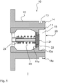
- the line coupling consists of a first coupling half 1 ( Fig. 1 ) and a second coupling half 2 ( Fig. 2 ) together.
- a first line train (not shown) is connected and to the right of the coupling half 2, a second line (not shown) is connected.
- the first coupling half 1 comprises a tubular housing 10 and a poppet valve 20.
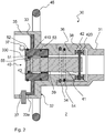
- the second coupling half comprises a three-part housing 30, a piston valve or plunger valve 40 and a manual drive 45.
- the tubular housing 10 of the first coupling half 1 comprises a valve seat part 11, which contains a conical valve seat 11 a and can be formed as a thermal barrier coating around the interior of the valve, and an outer pipe socket 12, which at the left end for connection to the first line and the right end for connection to the second coupling half 2 with a coupling groove 13 and a coupling flange 14 is formed.
- a coupling cavity 15 is further provided, which is provided with a good sliding material such Polytetrafluoillerhylen or a PTFE-containing material is equipped and has a cylindrical inner surface 15a.
- the poppet valve 20 includes a valve disk 21 having a conical ridge lip seal 22 made of polytetrafluoroethylene, PTFE-containing material or like material and pressed against the conical valve seat 11a by a biasing spring 23.
- a valve guide 24 ensures good axial guidance of the valve disk 21.
- the housing 30 of the second coupling half 2 comprises a tubular jacket housing 31, a bell-shaped drive housing 32 and a valve housing 33, which are nested on one another like a box.
- the drive housing 32 is rotatably supported in the jacket housing 31 by means of ball bearings 34 or another suitable bearing.
- Sheath housing 31 and drive housing 32 are sealed against each other by means of a Sp Drilllippendichtung 54.
- the Sp Dr Drichtung 54 seals the inside of the shell and the outside of the drive housing against each other.
- the bell shape of the drive housing 32 results from a ring portion 35 of larger diameter and a pipe section 36 of smaller diameter, which are interconnected via a disc portion.
- the ring portion 35 is lined with a friction reducing material such as polytetrafluoroethylene or a PTFE-containing material such as a PTFE / graphite composite and surrounds the valve housing 33.
- the tubular portion 36 of the drive housing 32 is provided with a thermal barrier coating based on polytetrafluoroethylene can be constructed.
- coupling pins 37 which are guided by guide grooves 14a (FIG. Fig. 1 ) through into the coupling groove 13 when coupling the coupling halves are practiced.
- extensions 33a of the valve housing 33 engage in the guide grooves 14a to lock the valve housing 33 against rotation.
- the piston or plunger valve 40 comprises a valve plunger 41 with piston body 410 (FIG. Fig. 4 ), which is displaceable by means of a sliding gear in the axial direction.
- the gate gear comprises a helical cam groove 38 in the tubular portion 36 of the drive housing 32, and a plunger 42 in the form of an axis extending transversely to the plunger with rollers 420 at the axle ends.
- the rollers 420 are guided in the cam groove 38.
- a conical stop 43 limits the displacement movement of the valve stem 41 in the closed position of the valve, while the other end position, which represents the open position of the valve, is predetermined by the slide groove 38.
- the drive of the slide mechanism via a hand wheel 45, which allows the drive housing 32 to rotate.
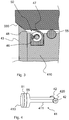
- Fig. 4 shows in perspective an embodiment of the valve stem 41.
- the valve stem 41 comprises a piston body 410 and a plate-shaped push rod 411.
- the plunger pin 42 extends in the center plane of the plate-shaped push rod 411 and transversely to the longitudinal direction of the valve stem 41 at the opposite end of the piston body 410.
- Fig. 3 shows a section through a Sp Schwarzlippendichtung 50.
- This includes a sealing body 46 made of polytetrafluoroethylene or a PTFE-containing material or a similar, at low temperatures still elastic material whose radial outwardly directed end forms a sealing lip 47, and a bent into a ring coil spring 48 of metal, which presses the sealing lip 47 against a smooth surface and thus seals a gap on the outside of the Sp Schwarzlippendichtung 50.
- Such a spreading lip seal 51 in Fig. 2 alone or in cooperation with a ring seal 55 can form a piston, which represents the valve element of the valve 40, or serve as a piston seal for the piston 410.
- a piston which represents the valve element of the valve 40
- the valve is closed, and when the piston body 410 has been moved out of the valve bore, the valve is opened.
- the housing 30 of the second coupling half shows various axially extending annular gaps, which are sealed by means of such Sp Schwarzlippendichtungen 50.
- the first expansion lip seal 51 functions as a valve member of Valve 40.
- a second expansion lip seal 52 serves to seal the annular gap between the front end of the valve housing 33 and the annular inner surface 15a of the housing 10 of the first coupling half 1.
- a third expansion lip seal 53 is interposed between the outside of the inner end of the valve housing 33 and an inner annular surface the ring portion 35 of the drive housing 32 joined.
- a fourth expansion lip seal 54 is located in an axial annular gap between the shell housing 31 and the drive housing 32 in the region of the tubular portion 36.
- the hand wheel 45 is rotated in the direction of return movement of the valve stem 41, wherein the annular seal 55 migrates into the valve bore of the valve housing, while the valve stem 41 aligns exactly axially. Thereafter, the Sp Schwarzlippendichtung 51 enters the axial annular gap between the valve housing 33 and plunger 41 and seals this annular gap. The return movement of the plunger 41 is limited by the conical stop 43. Now, the coupling pins 37 are in their circumferential position in alignment with the guide grooves 14a, so that the second coupling half. 2 can be deducted from the first coupling half 1.
- the stop 43 is preferably formed as a molded part made of PTFE and attached to the valve lifter 41.
Landscapes
- Engineering & Computer Science (AREA)
- General Engineering & Computer Science (AREA)
- Mechanical Engineering (AREA)
- Physics & Mathematics (AREA)
- Fluid Mechanics (AREA)
- Details Of Valves (AREA)
- Mechanically-Actuated Valves (AREA)
- Quick-Acting Or Multi-Walled Pipe Joints (AREA)
- Sealing With Elastic Sealing Lips (AREA)
Description
- Die Erfindung bezieht sich auf eine Leitungskupplung zur Verbindung einer ersten Leitung mit einer zweiten Leitung zwecks Durchleiten von Tieftemperatur- Medien. Als Medien kommen insbesondere Flüssigerdgas, verflüssigter Sauerstoff, Argon, Äthylen, Propylen, Äthen und andere in Betracht.
- Leitungskupplungen enthalten gewöhnlich zwei Kupplungshälften, von denen jede mit Sperreinrichtungen versehen sein kann, um beim Lösen der Kupplung die zugeordnete Leitung sofort zu schließen, um gefördertes Medium am Austritt zu hindern. Beim Kuppeln werden die Sperren gelöst und ein Strömungsweg wird zwischen der ersten und der zweiten Leitung freigegeben.
- Aus
DE 40 41 337 A1 ist eine Kupplung für Fluide bekannt, die ein aufnehmendes Kupplungsteil mit rohrförmigem Gehäuse und Kegelventil sowie ein eindringendes Kupplungsteil mit rohrförmigem Gehäuse und Kegelventil aufweist, wobei die beiden Kupplungsteile über einen Schraub- oder Bajonettverschluss miteinander verbunden werden können, der ein Steilgewinde aufweist, um das eindringende Kupplungsteil in das aufnehmende Kupplungsteil hinein zu verschieben. Das Kegelventil des aufnehmenden Kupplungsteiles weist einen ortsfesten Ventilkegel und einen federbelastenden nachgiebigen Ventilsitz auf. Der eindringende Kupplungsteil ist am vorderen Ende seines Gehäuses in Form eines Tellerventils ausgebildet, um mit dem beweglichen Ventilsitz des aufnehmenden Kupplungsteiles abdichtend zusammen zu arbeiten und dabei gleichzeitig das Kegelventil des eindringenden Kupplungsteil zu öffnen und den Ventilsitz des aufnehmenden Kupplungsteils relativ zu dem ortsfesten Ventilkegel zu verschieben und dadurch das Kegelventil des aufnehmenden Kupplungsteiles zu öffnen. - Aus
US 5 265 890 ist eine Dichtung aus Polytetrafluorethylen bekannt, die durch eine Elastomerfeder an abzudichtende Maschinenelemente ausdrückbar ist. - Wenn mit derartigen Leitungskupplungen Medien bei sehr tiefer Temperatur gehandhabt werden sollen, dann treten diverse Probleme im Zusammenhang mit "Kälteverlust" und gefrierender Feuchtigkeit, auch in Form von Dunst auf. In das Leitungssystem eindringende Wärme kann zur Verdampfung von tiefgekühlter Flüssigkeit führen, wodurch ein erheblicher Druck entsteht. Die gefrierende Nässe kann zu Schwergängigkeit oder sogar Einfrieren der Kupplung führen.
- Der Erfindung liegt deshalb die Aufgabe zugrunde, eine Leitungskupplung zur Verbindung von Leitungen vorzuschlagen, durch die auch Tieftemperatur - Medien bei Minimierung der besprochenen Probleme geleitet werden können.
- Die Bauweise der neuen Leitungskupplung soll auch für kleinere Baugrößen geeignet sein, wie sie für LKW-Tankwagen oder für kleinere Schiffe benötigt werden.
- Die Leitungskupplung weist im Zuge der ersten Leitung eine erste Kupplungshälfte und im Zuge der zweiten Leitung eine zweite Kupplungshälfte auf, die durch Eingriff von Kupplungszapfen in eine Kupplungsnut gekoppelt und verriegelt werden können.
- Die erste Kupplungshälfte umfasst ein Tellerventil mit Feder-vorgespanntem Ventilteller, der an einem konischen Ventilsitz anliegt, um normalerweise den Mediendurchgang durch das Ventil abzusperren. Durch Druck gegen die Kraft der Feder kann das Ventil aufgestoßen werden. Das Ventilinnere kann durch eine Wärmedämmschicht gegen eindringende Wärme geschützt werden. Die Wärmedämmschicht kann Polytetrafluoräthylen (PTFE) enthalten, um gute Gleiteigenschaften gegenüber kooperierenden Elementen aufzuweisen, was auch im Falle von Vereisung nützlich ist, da Eis nicht an Polytetrafluoräthylen haftet.
- Die zweite Kupplungshälfte weist ein dreiteiliges Gehäuse auf, und zwar ein äußeres rohrförmiges Mantelgehäuse, ein inneres Ventilgehäuse und ein dazwischen angeordnetes glockenförmiges Antriebsgehäuse mit einem Ringabschnitt größeren Durchmessers und einem Rohrabschnitt kleineren Durchmessers. Innerhalb des Ventilgehäuses ist ein neuartiges Ventil angeordnet, das als Kolbenventil oder als Stößelventil bezeichnet werden kann und dessen Ventilstößel in den Rohrabschnitt des Antriebsgehäuses hineinreicht und dort einen Stößelzapfen aufweist, der mit einer Kulissennut des Antriebsgehäuses zusammenarbeitet. Wenn die Kupplungshälften miteinander gekuppelt sind, lässt sich durch Drehen des Antriebsgehäuses der Ventilstößel axial verschieben, wodurch das Tellerventil der ersten Kupplungshälfte aufgestoßen und ein axialer Ringspalt am Stößelventil der zweiten Kupplungshälfte geöffnet wird, so dass der Mediendurchgang von der ersten zur zweiten Leitung durchgeschaltet ist.
- Der axiale Ringspalt zwischen Ventilgehäuse und Ventilstößel der zweiten Kupplungshälfte wird in der Schließstellung des Ventils von einem Kolben abgedichtet, der, neben einem Kolbenkörper, von einer (ersten) Spreizlippendichtung, gegebenenfalls in Unterstützung durch eine Schnurringdichtung, gebildet wird. Die Spreizlippendichtung enthält einen ringförmigen Dichtkörper mit Dichtlippe aus einem ausreichend elastischen Material bei tiefen Temperaturen und eine Spreizringfeder, die die Dichtlippe radial nach außen gegen die Wandung des Ventilgehäuses drängt. Auf diese Weise wird gewährleistet, dass auch bei tiefen Temperaturen der axiale Ringspalt zwischen Ventilgehäuse und Ventilstößel abgedichtet wird, wobei die axiale Stellung des Ventilstößels in einem gewissen Verschiebebereich des Kolbens im Hinblick auf Abdichtung unkritisch ist. (Dies steht im Gegensatz zur Abdichtung mit einem Ventilteller, der genau am konischen Ventilsitz anliegen muss, um abzudichten.)
- Als Material des ringförmigen Dichtkörpers mit Dichtlippe der Spreizlippendichtung wird Polytetrafluoräthylen oder ein PTFE-haltiger Werkstoff oder ein Material mit ähnlichen Eigenschaften bevorzugt. Solches Material ist bei tiefen Temperaturen noch ausreichend elastisch und löst sich leicht von Eisschichten, die sich in Folge von Feuchtigkeit und unter tiefer Temperatur am Ventil bilden könnten. Als PTFE-haltige Werkstoffe können insbesondere Kompositmaterialien, wie etwa ein PTFE/Graphit-Werktstoff verwendet werden.
- Überall, wo es bei der Tieftemperatur -Leitungskupplung axiale Ringspalte gibt, werden bevorzugt Spreizlippendichtungen der beschriebenen Bauart verwendet. Dies bezieht sich auf den axialen Ringspalt zwischen dem vorstehenden Ende des Ventilgehäuses der zweiten Kupplungshälfte und den dieses Ende umgreifenden Kupplungsflansch der ersten Kupplungshälfte. Eine weitere Stelle für eine Spreizlippendichtung findet sich zwischen dem inneren Flanschende des Ventilgehäuses und dem dieses Ende übergreifenden Antriebsgehäuse. Auch in einem Ringspalt zwischen Mantelgehäuse und Antriebsgehäuse kann eine Spreizlippendichtung angeordnet werden.
- Bei dem Tellerventil der ersten Kupplungshälfte gibt es eine Vorspannungsfeder, welche das konische Dichtelement gegen den konischen Ventilsitz drängt. Hier wird vorteilhaft eine Presslippendichtung aus Polytetrafluoräthylen, einem PTFE-haltigen Werkstoff oder einem gleichartigen Werkstoff angewandt.
- Um die Ventilstößel des in der zweiten Kupplungshälfte angeordneten Stößelventils in die Offenstellung und in die Geschlossenstellung zu verschieben, wird ein Kulissengetriebe mit einer schraubenförmigen Kulissennut und mit einem in diese eingreifenden Stößelzapfen benutzt, der am Ventilstößel angebracht ist, der wiederum in axialer Richtung geführt ist. Die Kulissennut ist in dem Antriebsgehäuse untergebracht und der Stößelzapfen kann eine Achse mit Rollen an deren Enden darstellen. Wenn die Kupplungshälften miteinander gekuppelt und verriegelt sind, wird das (zuvor freie) Ende des Ventilgehäuses durch Eingriff am Gehäuse des Tellerventils festgehalten, und die axiale Führung am Stößelventil gibt dem Ventilstößel eine axiale Längsbewegung vor, die durch die Übersetzung der Drehbewegung des Antriebsgehäuses in eine Längsbewegung des Ventilstößels in Folge des Kulissengetriebes erzeugt wird. Bei seiner axialen Längsbewegung stößt der Ventilstößel gegen das Tellerventil und öffnet dieses entgegen der Kraft der Vorspannungsfeder des Tellerventils. Gleichzeitig wandert bei der Verschiebung des Ventilstößels die mitgeführte Spreizlippendichtung aus dem Ringspalt zwischen Ventilgehäuse und Stößel heraus, der Ringspalt wird frei und ermöglicht den Durchgang von Medien durch beide Ventile.
- Das Innere beider Ventile kann durch Wärmedämmschichten gegen Eindringen der Wärme geschützt werden. Darüber hinaus können Spalte, die zwischen bewegten Teilen der Leitungskupplung existieren, mit einer gut gleitfähigen Oberfläche versehen werden. Polytetrafluoräthylen oder allgemeiner ein PTFE-haltiger Werkstoff, wie etwa auch ein PTFE/Graphit-Kompositmaterial eignet sich als Material mit guten Gleiteigenschaften und auch zur Wärmedämmung. Feuchtigkeitsniederschlag wird gehemmt und Eisbildung leicht von der Oberfläche abgelöst. Das Einfrieren der Leitungskupplung wird so vermieden.
- Ein Ausführungsbeispiel der Erfindung wird anhand der Zeichnungen beschrieben. Dabei zeigt:
-
Fig. 1 einen Längsschnitt durch eine erste Kupplungshälfte, -
Fig. 2 einen Längsschnitt durch eine zweite Kupplungshälfte, -
Fig. 3 einen Längsschnitt durch eine Spreizlippendichtung, und -
Fig. 4 eine Ansicht eines Ventilstössels der zweiten Kupplungshälfte. - Die Leitungskupplung setzt sich aus einer ersten Kupplungshälfte 1 (
Fig. 1 ) und einer zweiten Kupplungshälfte 2 (Fig. 2 ) zusammen. Links von der ersten Kupplung 1 ist ein erster Leitungszug (nicht dargestellt) angeschlossen und rechts von der Kupplungshälfte 2 ist eine zweite Leitung (nicht dargestellt) angeschlossen. Die erste Kupplungshälfte 1 umfasst ein rohrförmiges Gehäuse 10 und ein Tellerventil 20. Die zweite Kupplungshälfte umfasst ein dreiteiliges Gehäuse 30, ein Kolbenventil oder Stößelventil 40 und einen Handantrieb 45. - Das rohrförmige Gehäuse 10 der ersten Kupplungshälfte 1 umfasst einen Ventilsitzteil 11, der einen konischen Ventilsitz 11a enthält und als eine Wärmedämmschicht um das Innere des Ventils ausgebildet sein kann, und einen äußeren Rohrstutzen 12, der am linken Ende zum Anschluss an die erste Leitung und am rechten Ende zum Anschluss an die zweite Kupplungshälfte 2 mit einer Kupplungsnut 13 und einem Kupplungsflansch 14 ausgebildet ist. Am rechten Ende des Gehäuses 10 ist ferner ein Kupplungshohlraum 15 vorhanden, der mit einem gut gleitfähigen Material wie Polytetrafluoräthylen oder einem PTFE-haltigen Werkstoff ausgestattet ist und eine zylindrische Innenfläche 15a aufweist. Das Tellerventil 20 umfasst einen Ventilteller 21 mit einer konischen Presslippendichtung 22, die aus Polytetrafluoräthylen, PTFE-haltigem Material oder einem gleichartigen Material besteht und an den konischen Ventilsitz 11a durch eine Vorspannungsfeder 23 gepresst wird. Eine Ventilführung 24 sorgt für gute axiale Führung des Ventiltellers 21.
- Das Gehäuse 30 der zweiten Kupplungshälfte 2 umfasst ein rohrförmiges Mantelgehäuse 31, ein glockenförmiges Antriebsgehäuse 32 und ein Ventilgehäuse 33, die zwiebelartig ineinander geschachtelt sind. Das Antriebsgehäuse 32 ist mittels Kugellager 34 oder einer anderen geeigneten Lagerung in dem Mantelgehäuse 31 drehbar gelagert. Mantelgehäuse 31 und Antriebsgehäuse 32 sind mittels einer Spreizlippendichtung 54 gegeneinander abgedichtet. Bei der dargestellten Ausführungsform dichtet die Spreizlippendichtung 54 dabei die Innenseite des Mantelgehäuses und die Aussenseite des Antriebsgehäuses gegeneinander ab. Die Glockenform des Antriebsgehäuses 32 ergibt sich aus einem Ringabschnitt 35 größeren Durchmessers und einem Rohrabschnitt 36 kleineren Durchmessers, die über einen Scheibenabschnitt miteinander verbunden sind. Der Ringabschnitt 35 ist mit einem reibungsvermindernden Material wie Polytetrafluoräthylen oder einem PTFE-haltigen Werkstoff, wie etwa ein PTFE/Graphit-Komposit ausgekleidet und umgibt das Ventilgehäuse 33. Der Rohrabschnitt 36 des Antriebsgehäuses 32 ist mit einer Wärmedämmschicht versehen, die auf der Basis von Polytetrafluoräthylen aufgebaut sein kann. Im Inneren des Ringabschnittes 35 befinden sich Kupplungszapfen 37, die durch Führungsnuten 14a (
Fig. 1 ) hindurch in die Kupplungsnut 13 beim Kuppeln der Kupplungshälften praktiziert werden. Gleichzeitig greifen Fortsätze 33a des Ventilgehäuses 33 in die Führungsnuten 14a, um das Ventilgehäuse 33 gegen Drehung festzulegen. - Das Kolben- oder Stößelventil 40 umfasst einen Ventilstößel 41 mit Kolbenkörper 410 (
Fig. 4 ), der mittels eines Kulissengetriebes in axialer Richtung verschiebbar ist. Das Kulissengetriebe umfasst eine schraubenförmige Kulissennut 38 im rohrförmigen Abschnitt 36 des Antriebsgehäuses 32, und einen Stößelzapfen 42 in Form einer sich quer zum Stößel erstreckenden Achse mit Rollen 420 an den Achsenden. Die Rollen 420 werden in der Kulissennut 38 geführt. Zu dem Kulissengetriebe zählt noch eine Stößellängsführung 39 am Ventilgehäuse 33. Ein kegelförmiger Anschlag 43 begrenzt die Verschiebebewegung des Ventilstößels 41 in der Geschlossenstellung des Ventils, während die andere Endstellung, welche die Offenstellung des Ventils darstellt, durch die Kulissennut 38 vorgegeben wird. Der Antrieb des Kulissengetriebes erfolgt über ein Handrad 45, das das Antriebsgehäuse 32 zu drehen ermöglicht. -
Fig. 4 zeigt perspektivisch eine Ausführungsform des Ventilstößels 41. Wie anhand vonFig. 4 ersichtlich, umfasst der Ventilstößel 41 einen Kolbenkörper 410 und eine plattenförmige Stösselstange 411. Der Stößelzapfen 42 erstreckt sich in der Mittenebene der plattenförmigen Stösselstange 411 und quer zur Längsrichtung des Ventilstössels 41 an dem dem Kolbenkörper 410 gegenüberliegenden Ende. Durch die plattenförmige Ausführung der Stößelstange wird Strömungsraum gewonnen und eine Längsführung beim Öffnen und Schließen des Stößelventils 40 durch die Stößellängsführung 39 ermöglicht. -
Fig. 3 zeigt einen Schnitt durch eine Spreizlippendichtung 50. Diese umfasst einen Dichtungskörper 46 aus Polytetrafluoräthylen oder einem PTFE-haltigen Werkstoff oder einem ähnlichen, bei tiefen Temperaturen noch elastischen Werkstoff, dessen radiales nach außen gerichtetes Ende eine Dichtlippe 47 bildet, und eine zu einem Ring gebogene Schraubenfeder 48 aus Metall, die die Dichtlippe 47 gegen eine glatte Fläche drückt und somit einen Spalt an der Außenseite der Spreizlippendichtung 50 abdichtet. - Eine solche Spreizlippendichtung 51 in
Fig. 2 kann allein oder in Zusammenwirken mit einer Ringdichtung 55 einen Kolben bilden, der das Ventilelement des Ventils 40 darstellt, oder als Kolbendichtung für den Kolben 410 dienen. Wenn der Kolben 410 sich in der Ventilbohrung befindet, ist das Ventil geschlossen, und wenn der Kolbenkörper 410 aus der Ventilbohrung herausgefahren worden ist, ist das Ventil geöffnet. Zur erleichterten Herbeiführung der Schließstellung gibt es eine Einführungsschräge 330 für die Dichtungen 51,55 am Eingang zur Ventilbohrung. - Das Gehäuse 30 der zweiten Kupplungshälfte zeigt diverse axial sich erstreckende Ringspalte, die mittels solcher Spreizlippendichtungen 50 abgedichtet sind. Die erste Spreizlippendichtung 51 fungiert als Ventilelement des Ventils 40. Eine zweite Spreizlippendichtung 52 dient zur Abdichtung des Ringspaltes zwischen dem vorderen Ende des Ventilgehäuse 33 und der ringförmigen Innenfläche 15a des Gehäuses 10 der ersten Kupplungshälfte 1. Eine dritte Spreizlippendichtung 53 ist zwischen der Außenseite des inneren Endes des Ventilgehäuses 33 und einer inneren Ringfläche des Ringabschnittes 35 des Antriebsgehäuses 32 gefügt. Eine vierte Spreizlippendichtung 54 befindet sich in einem axialen Ringspalt zwischen dem Mantelgehäuse 31 und dem Antriebsgehäuse 32 im Bereich des rohrförmigen Abschnittes 36. Alle diese Spreizlippendichtungen sorgen dafür, dass Feuchtigkeit möglichst weitgehend vom Inneren der zweiten Kupplungshälfte ferngehalten wird und dass, wenn sich dort Eis niederschlagen sollte, die gute Gleiteigenschaft der Dichtung dafür sorgt, dass das gebildete Eis sich schon bei leichter Querkraft löst. Dadurch wird Schwergängigkeit bei zu erwartendem rauen Betrieb der Leitungskupplung vermieden.
- Die Handhabung der Leitungskupplung ist wie folgt:
- Es sei angenommen, dass die Kupplungshälfte 1 ortsfest angebracht ist und die Kupplungshälfte 2 sich am Ende eines Schlauches befindet. Die zweite Kupplungshälfte 2 wird mit dem ringförmigen Gehäuseteil 35 über den Flansch 14 der ersten Kupplungshälfte 1 geschoben, wobei das linke Ende des Ventilgehäuses 33 in den Ringraum 15 der ersten Kupplungshälfte gelangt und die Kupplungszapfen 37 durch die Führungnuten 14a hindurch gleiten und bis in die Kupplungsnut 13 gelangen. Gleichzeitig gelangen die Fortsätze 33a des Ventilgehäuses 33 in die Führungsnuten 14a des stationären Gehäuses 10.
- Als dann werden die beiden Kupplungshälften durch Drehen am Handrad 45 gegeneinander verriegelt. Weiteres Drehen des Handrades 45 führt zum Antrieb des Kulissengetriebes, wobei der Ventilstößel 41 sich in
Fig. 2 nach links verschiebt und dadurch auf das linke Ende des Ventiltellers 21 trifft, der gegen die Kraft der Feder 23 nach links (Fig. 1 ) verschoben wird. Dadurch wird ein konischer Spalt zwischen der Dichtung 22 und dem Ventilsitz 11a geöffnet, durch den Medium strömen kann. Mit der Verschiebung des Ventilstößels 41 in der Zeichnung nach links wandert der Kolbenkörper 410 zusammen mit der Spreizlippendichtung 51 und der Ringdichtung 55 aus dem axialen Ringspalt zwischen Ventilgehäuse 33 und Ventilstößel 41 heraus, so dass der Durchgang von Medium durch diesen Ringspalt ermöglicht wird. Je nach dem Druckgefälle strömt Medium von der ersten Leitung in die erste Kupplungshälfte und von dort durch die zweite Kupplungshälfte in die zweite Leitung, oder umgekehrt. Die Spreizlippendichtungen 52, 53 und 54 sorgen dafür, dass kein Medium nach außen gelangen kann. - Zum Trennen der Kupplungshälften wird das Handrad 45 in Richtung auf Rückbewegung des Ventilstößels 41 gedreht, wobei die Ringdichtung 55 in die Ventilbohrung des Ventilgehäuses hinein wandert und dabei den Ventilstößel 41 genau axial ausrichtet. Danach gelangt die Spreizlippendichtung 51 in den axialen Ringspalt zwischen Ventilgehäuse 33 und Stößel 41 und dichtet diesen Ringspalt ab. Die Rückzugsbewegung des Stößels 41 wird durch den konischen Anschlag 43 begrenzt. Nunmehr befinden sich die Kupplungszapfen 37 in ihrer Umfangsstellung fluchtend zu den Führungsnuten 14a, so dass die zweite Kupplungshälfte 2 von der ersten Kupplungshälfte 1 abgezogen werden kann. Der Anschlag 43 ist bevorzugt als Formteil aus PTFE ausgebildet und am Ventilstößel 41 befestigt.
- Sollte sich wegen des starken Temperaturgefälles zwischen Innen und Außen der Kupplung Eis in Spalten niedergeschlagen haben, dann werden bei der Drehung des Handrades 45 Querkräfte auf das niedergeschlagene Eis ausgeübt, die zum Lösen des Eisfilms von mit Polytetrafluoräthylen oder PTFE-haltigem Material ausgekleideten Dichtstellen führt. Trotz schwieriger, äußerer Bedingungen lässt sich das Gerät einfach bedienen.
Claims (14)
- Leitungskupplung zur Verbindung einer ersten Leitung mit einer zweiten Leitung, um einen Mediendurchgang für Tieftemperatur -Medien zu öffnen oder zu sperren, umfassend:- eine im Zuge der ersten Leitung angeordnete erste Kupplungshälfte (1), die ein erstes rohrförmiges Gehäuse (10) mit einer äußeren Kupplungsnut (13) aufweist sowie ein Tellerventil (20) mit Feder-vorgespanntem Ventilteller (21) umfasst, der normalerweise den Mediendurchgang absperrt, jedoch aufgestoßen werden kann;- eine im Zuge der zweiten Leitung angeordnete zweite Kupplungshälfte (2), die auf die erste Kupplungshälfte (1) aufgesetzt werden kann, um einen Kupplungszapfen (37) in die Kupplungsnut (13) der ersten Kupplungshälfte (1) eingreifen zu lassen, wobei die zweite Kupplungshälfte (2) ein zweites, dreiteiliges Gehäuse (30) mit einem rohrförmigem Mantelgehäuse (31), einem glockenförmigen Antriebsgehäuse (32) und einem Ventilgehäuse (33) aufweist sowie ein Stößelventil (40) mit Ventilstößel (41) und Ventilkolben (410) umfasst, der normalerweise den Mediendurchgang durch einen axialen Ringspalt am Ventilgehäuse (33) absperrt, jedoch bei axialer Verschiebung durch das Antriebsgehäuse (32) den Mediendurchgang freigibt, wobei das Antriebsgehäuse (32) unterschiedliche Dreh- Bewegungsstellungen einnehmen kann, um den Kupplungszapfen (37) zum Eingriff in die Kupplungsnut (13) und außer Eingriff zu bringen und um eine am Antriebsgehäuse (32) angebrachte Kulissennut (38) zu drehen und damit einen Stößelzapfen (42) des Stößelventils (40) sowie den Ventilstößel (41) anzutreiben und den Ventilkolben (410) in die Öffnungs- oder Schließstellung zu führen, sowie das Tellerventil (20) der ersten Kupplungshälfte (1) zu betätigen; und- eine erste Spreizlippendichtung (51), die einen in einer Ringnut des Ventilkolbens (410) angeordneten Dichtungskörper (46) und eine radial nach außen gerichtete Dichtlippe (47) aufweist und als Element des Ventilkolbens (410) den axialen Ringspalt zwischen Ventilgehäuse (33) und Ventilstößel (41) in Abhängigkeit von der Bewegungsstellung des Antriebsgehäuses (32) schließt oder öffnet.
- Leitungskupplung nach Anspruch 1,
wobei das erste rohrförmige Gehäuse (10) einen radialen Kupplungsflansch (14) mit erster axialer ringförmiger Innenfläche (15) und das Ventilgehäuse (33) der zweiten Kupplungshälfte (2) ein erstes axiales Flanschende umfasst, das eine zweite Spreizlippendichtung (52), passend zur Zusammenarbeit mit der ersten axialen ringförmigen Innenfläche (15), aufweist. - Leitungskupplung nach Anspruch 1 oder 2,
wobei das glockenförmige Antriebsgehäuse (32) eine zweite axiale, ringförmige Innenfläche und das Ventilgehäuse (33) ein zweites axiales Flanschende umfasst, das eine dritte Spreizlippendichtung (53), passend zur Zusammenarbeit mit der zweiten axialen, ringförmigen Innenfläche, aufweist. - Leitungskupplung nach einem der Ansprüche 1 bis 3,
wobei das Mantelgehäuse (31) der zweiten Kupplungshälfte (2) eine dritte axiale, ringförmige Innenfläche und das Antriebsgehäuse (32) der zweiten Kupplungshälfte (2) eine äußere Ringfläche mit einer vierten Spreizlippendichtung (54) umfasst, die mit der dritten axialen, ringförmigen Innenfläche des Mantelgehäuses (31) zusammenarbeitet. - Leitungskupplung nach einem der Ansprüche 1 bis 4,
wobei am Ventilkolben (410) parallel zur ersten Spreizlippendichtung (51) eine Ringdichtung (55) angeordnet ist. - Leitungskupplung nach einem der Ansprüche 1 bis 5,
wobei der Ventilteller (21) der ersten Kupplungshälfte (1) eine konische Presslippendichtung (22) aufweist. - Leitungskupplung nach einem der Ansprüche 1 bis 6,
wobei am glockenförmigen Antriebsgehäuse (32) der zweiten Kupplungshälfte (2) ein Handrad (45) angebracht ist, um durch Eingriff der Kupplungszapfen (37) in die Kupplungsnut (13) und durch Drehung des Antriebsgehäuses (32) gegenüber dem ersten rohrförmigen Gehäuse (10) die Kupplungshälften zu verriegeln. - Leitungskupplung nach einem der Ansprüche 1 bis 7,
wobei die Kulissennut (38) schraubenförmig ausgebildet ist. - Leitungskupplung nach einem der Ansprüche 1 bis 8,
wobei der Stößelzapfen (42) als eine mit Rollen versehene Achse ausgebildet ist, die quer zur Bewegungsrichtung des Ventilstößels (41) angeordnet ist. - Leitungskupplung nach einem der Ansprüche 1 bis 9,
wobei das glockenförmige Antriebsgehäuse (32) einen Ringabschnitt (35) größeren Durchmessers und einen Rohrabschnitt (36) kleineren Durchmessers aufweist - Leitungskupplung nach einem der Ansprüche 1 bis 10,
wobei im Bereich von wenigstens einem der Ringspalte zwischen gegeneinander bewegbaren Geräteelementen sich reibungsmindernde Auskleidungen befinden. - Leitungskupplung nach Anspruch 11,
wobei die reibungsmindernden Auskleidungen aus Polytetrafluoräthylen enthaltenden Schichten bestehen. - Leitungskupplung nach einem der Ansprüche 1 bis 12,
wobei das rohrförmige Gehäuse (10) der ersten Kupplungshälfte (1) eine Wärmedämmschicht (11) aufweist. - Leitungskupplung nach einem der Ansprüche 10 bis 13,
wobei das glockenförmige Antriebsgehäuse (32) der zweiten Kupplungshälfte (2) eine Wärmedämmschicht auf der Innenseite des Ringabschnittes (35) und eine weitere Wärmedämmschicht auf der Außenseite des Rohrabschnittes (36) aufweist.
Priority Applications (1)
| Application Number | Priority Date | Filing Date | Title |
|---|---|---|---|
| PL13729290T PL2859263T3 (pl) | 2012-06-11 | 2013-06-05 | Niskotemperaturowe złącze przewodowe |
Applications Claiming Priority (2)
| Application Number | Priority Date | Filing Date | Title |
|---|---|---|---|
| DE102012104990.4A DE102012104990B4 (de) | 2012-06-11 | 2012-06-11 | Tieftemperatur - Leitungskupplung |
| PCT/EP2013/061597 WO2013186100A1 (de) | 2012-06-11 | 2013-06-05 | Tieftemperatur - leistungskupplung |
Publications (2)
| Publication Number | Publication Date |
|---|---|
| EP2859263A1 EP2859263A1 (de) | 2015-04-15 |
| EP2859263B1 true EP2859263B1 (de) | 2017-02-01 |
Family
ID=48628631
Family Applications (1)
| Application Number | Title | Priority Date | Filing Date |
|---|---|---|---|
| EP13729290.0A Active EP2859263B1 (de) | 2012-06-11 | 2013-06-05 | Tieftemperatur - leitungskupplung |
Country Status (10)
| Country | Link |
|---|---|
| US (1) | US9435475B2 (de) |
| EP (1) | EP2859263B1 (de) |
| JP (1) | JP6193982B2 (de) |
| KR (1) | KR101893546B1 (de) |
| CN (1) | CN104520628B (de) |
| CA (1) | CA2871551C (de) |
| DE (1) | DE102012104990B4 (de) |
| ES (1) | ES2614925T3 (de) |
| PL (1) | PL2859263T3 (de) |
| WO (1) | WO2013186100A1 (de) |
Cited By (1)
| Publication number | Priority date | Publication date | Assignee | Title |
|---|---|---|---|---|
| WO2024154041A1 (en) * | 2023-01-17 | 2024-07-25 | Boll & Kirch Filterbau Gmbh | Switching device for cryogenic fluids and multiple filter arrangement for cryogenic fluids |
Families Citing this family (12)
| Publication number | Priority date | Publication date | Assignee | Title |
|---|---|---|---|---|
| CN105221879B (zh) * | 2015-10-21 | 2017-12-26 | 武汉三江航天远方科技有限公司 | 船用加注站快速接头 |
| GB2550933B (en) * | 2016-06-01 | 2019-01-16 | Taylor Kerr Couplings Ltd | Self-aligning pipe coupling |
| CN106555896B (zh) * | 2017-01-15 | 2019-05-10 | 厦门建霖健康家居股份有限公司 | 一种管自身变形防止产品冰冻失效结构及其方法 |
| US12085209B2 (en) * | 2020-04-24 | 2024-09-10 | Aerojet Rocketdyne, Inc. | Valve device with ball locks |
| CN112082024A (zh) * | 2020-08-26 | 2020-12-15 | 中航光电科技股份有限公司 | 一种旋转快锁式流体连接器组件 |
| KR102415368B1 (ko) * | 2020-08-27 | 2022-07-01 | 주식회사 엠에스이엔지 | 유압식 비상 분리 커플링 |
| CN114321530A (zh) * | 2020-09-30 | 2022-04-12 | 上海极智机电设备有限公司 | 具有防爆功能的油管接头 |
| CN112576827B (zh) * | 2020-12-18 | 2022-11-08 | 中航光电科技股份有限公司 | 一种流体连接器及连接器组件 |
| WO2022251878A1 (en) * | 2021-05-28 | 2022-12-01 | Engineered Controls International, Llc | Low-emission nozzle and receptacle coupling for cryogenic fluid |
| EP4367427A4 (de) | 2021-07-09 | 2024-08-07 | Colder Products Company | Kompakte fluidkupplungen |
| CN114719103B (zh) * | 2022-04-01 | 2025-06-17 | 广东泰恩流体控制设备有限公司 | 一种干式接头 |
| US20250305591A1 (en) * | 2024-04-01 | 2025-10-02 | Co-Luck Enterprise Co., Ltd. | Valve connector |
Citations (2)
| Publication number | Priority date | Publication date | Assignee | Title |
|---|---|---|---|---|
| DE4041337A1 (de) * | 1990-12-21 | 1992-06-25 | Bayerische Motoren Werke Ag | Kupplung fuer fluide |
| US5265890A (en) * | 1990-12-03 | 1993-11-30 | Peter J. Balsells | Seal with spring energizer |
Family Cites Families (19)
| Publication number | Priority date | Publication date | Assignee | Title |
|---|---|---|---|---|
| US597549A (en) | 1898-01-18 | Horseshoe-pad | ||
| US1812038A (en) * | 1926-03-18 | 1931-06-30 | Alemite Corp | Coupling |
| US1996900A (en) * | 1933-12-20 | 1935-04-09 | William A Backner | Quick coupling valve with lock cover |
| US3112766A (en) * | 1960-08-29 | 1963-12-03 | Thompson Ramo Wooldridge Inc | Quick disconnect fluid coupling |
| US3842614A (en) * | 1973-10-12 | 1974-10-22 | Hansen Mfg Co | Cryogenic coupling assembly |
| US4030524A (en) * | 1975-05-19 | 1977-06-21 | Dover Corporation | Coupler |
| US5404909A (en) * | 1992-06-11 | 1995-04-11 | Parker-Hannifin Corporation | Coupling device |
| US5363879A (en) * | 1994-02-15 | 1994-11-15 | Liquid Carbonic Corporation | Cryogenic coupling |
| US5975491A (en) * | 1996-11-18 | 1999-11-02 | Ab Todo Produktions & Forsaljningsbolag | Coupling |
| DE19724120B4 (de) * | 1997-06-09 | 2007-03-29 | Carl Kurt Walther Gmbh & Co Kg | Schnellverschlußkupplung |
| DE19727655A1 (de) * | 1997-06-30 | 1999-01-07 | Messer Griesheim Gmbh | Kupplung zum Verbinden vakuumisolierter Leitungsenden |
| FR2794840B1 (fr) * | 1999-06-14 | 2001-09-07 | Raoul Fremy | Raccord de conduit |
| US6945477B2 (en) | 2002-09-04 | 2005-09-20 | Parker-Hannifin Corporation | Cryogenic coupling device |
| US7117892B2 (en) * | 2003-10-24 | 2006-10-10 | Hiltap Fittings, Ltd. | Quick disconnect valve assembly |
| WO2006091234A2 (en) | 2004-07-27 | 2006-08-31 | Parker-Hannifin Corporation | Quick disconnect cryogenic coupler |
| BRPI0706655A2 (pt) * | 2006-01-19 | 2011-04-05 | Single Buoy Moorings | estrutura de acoplamento |
| US7908934B2 (en) * | 2008-02-29 | 2011-03-22 | Dionex Corporation | Valve assembly |
| US8397755B2 (en) * | 2010-02-02 | 2013-03-19 | Daiwa Can Company | Coupler with stop valve |
| CN201688068U (zh) | 2010-06-02 | 2010-12-29 | 平顶山市碧源科技有限公司 | 一种钩挂式快插连接件 |
-
2012
- 2012-06-11 DE DE102012104990.4A patent/DE102012104990B4/de not_active Expired - Fee Related
-
2013
- 2013-06-05 CA CA2871551A patent/CA2871551C/en active Active
- 2013-06-05 PL PL13729290T patent/PL2859263T3/pl unknown
- 2013-06-05 ES ES13729290.0T patent/ES2614925T3/es active Active
- 2013-06-05 WO PCT/EP2013/061597 patent/WO2013186100A1/de not_active Ceased
- 2013-06-05 JP JP2015516556A patent/JP6193982B2/ja active Active
- 2013-06-05 CN CN201380024564.2A patent/CN104520628B/zh active Active
- 2013-06-05 EP EP13729290.0A patent/EP2859263B1/de active Active
- 2013-06-05 US US14/407,359 patent/US9435475B2/en not_active Expired - Fee Related
- 2013-06-05 KR KR1020147034342A patent/KR101893546B1/ko active Active
Patent Citations (2)
| Publication number | Priority date | Publication date | Assignee | Title |
|---|---|---|---|---|
| US5265890A (en) * | 1990-12-03 | 1993-11-30 | Peter J. Balsells | Seal with spring energizer |
| DE4041337A1 (de) * | 1990-12-21 | 1992-06-25 | Bayerische Motoren Werke Ag | Kupplung fuer fluide |
Cited By (1)
| Publication number | Priority date | Publication date | Assignee | Title |
|---|---|---|---|---|
| WO2024154041A1 (en) * | 2023-01-17 | 2024-07-25 | Boll & Kirch Filterbau Gmbh | Switching device for cryogenic fluids and multiple filter arrangement for cryogenic fluids |
Also Published As
| Publication number | Publication date |
|---|---|
| JP2015528087A (ja) | 2015-09-24 |
| WO2013186100A1 (de) | 2013-12-19 |
| CN104520628A (zh) | 2015-04-15 |
| KR101893546B1 (ko) | 2018-08-30 |
| US20150114500A1 (en) | 2015-04-30 |
| KR20150037751A (ko) | 2015-04-08 |
| EP2859263A1 (de) | 2015-04-15 |
| JP6193982B2 (ja) | 2017-09-06 |
| DE102012104990B4 (de) | 2017-02-02 |
| CA2871551C (en) | 2017-06-20 |
| US9435475B2 (en) | 2016-09-06 |
| DE102012104990A1 (de) | 2013-12-12 |
| PL2859263T3 (pl) | 2017-07-31 |
| ES2614925T3 (es) | 2017-06-02 |
| CA2871551A1 (en) | 2013-12-19 |
| CN104520628B (zh) | 2016-09-07 |
Similar Documents
| Publication | Publication Date | Title |
|---|---|---|
| EP2859263B1 (de) | Tieftemperatur - leitungskupplung | |
| EP2828566B1 (de) | Kupplung zum anschluss fluidführender leitungen | |
| DE102012209629B4 (de) | Aufnahmeteil einer Trockenkupplung | |
| EP3842681A1 (de) | Schnell trennende johnston-kupplung | |
| DE1286360B (de) | Flachdrehschieber | |
| DE2141161A1 (de) | Kolbenantrieb zur Herbeiführung einer Drehbewegung | |
| DE2347867A1 (de) | Schnellschliessvorrichtung fuer ventil | |
| EP0421194B1 (de) | Spritzpistole für ein Hochdruckreinigungsgerät | |
| DE1475666A1 (de) | Mit einer OEffnungs- und Schliessvorrichtung versehene Rohrleitungskupplung | |
| EP1883766B1 (de) | Betätigungsvorrichtung für eine schnellanschlusskupplung | |
| WO2003074309A2 (de) | Anschlusskupplung | |
| DE202016103458U1 (de) | Absperrarmatur für Rohrleitungen | |
| EP2031290B9 (de) | Kupplungsvorrichtung zum dichtenden Verbinden von flüssige oder gasförmige Medien transportierenden Förderleitungen | |
| EP2193092B1 (de) | Andockeinrichtung aus zwei kupplungsverschlüssen zum umweltdichten transfer von schüttgut, enthaltend mindestens eine verriegelungseinheit | |
| DE2342069B2 (de) | Kugelhahn mit frei beweglichen dichtungssitzringen | |
| DE102009035986A1 (de) | Doppelmantelrohr mit integriertem Rücklauf und Entlüftung | |
| EP2054649B1 (de) | Absperrarmatur | |
| EP2813742B1 (de) | Schnellanschlusskupplung | |
| EP1258662B1 (de) | Vorrichtung zum Absperren von von Fluiden durchströmten Rohrleitungen mittels eines kugelförmigen Verschlusskörper | |
| DE102016203519B4 (de) | Ventilkörper und Verbindungseinrichtung für ein medizinisches Infusionssystem | |
| DE10031450A1 (de) | Doppelsitz-Klappventil mit Leckagesicherung | |
| EP3667146B1 (de) | Kupplung für fluide | |
| AT237982B (de) | Absperrvorrichtung | |
| DE2028886C (de) | Schlauch- oder Rohrkupplung großer Nennweite | |
| DE2425139A1 (de) | Armatur fuer rohrleitungen zum transport von medien |
Legal Events
| Date | Code | Title | Description |
|---|---|---|---|
| PUAI | Public reference made under article 153(3) epc to a published international application that has entered the european phase |
Free format text: ORIGINAL CODE: 0009012 |
|
| 17P | Request for examination filed |
Effective date: 20141210 |
|
| AK | Designated contracting states |
Kind code of ref document: A1 Designated state(s): AL AT BE BG CH CY CZ DE DK EE ES FI FR GB GR HR HU IE IS IT LI LT LU LV MC MK MT NL NO PL PT RO RS SE SI SK SM TR |
|
| AX | Request for extension of the european patent |
Extension state: BA ME |
|
| DAX | Request for extension of the european patent (deleted) | ||
| 17Q | First examination report despatched |
Effective date: 20160107 |
|
| REG | Reference to a national code |
Ref country code: DE Ref legal event code: R079 Ref document number: 502013006258 Country of ref document: DE Free format text: PREVIOUS MAIN CLASS: F16L0017025000 Ipc: F16L0025060000 |
|
| GRAP | Despatch of communication of intention to grant a patent |
Free format text: ORIGINAL CODE: EPIDOSNIGR1 |
|
| RIC1 | Information provided on ipc code assigned before grant |
Ipc: F16L 37/30 20060101ALI20160718BHEP Ipc: F16L 17/025 20060101ALI20160718BHEP Ipc: F16J 15/00 20060101ALI20160718BHEP Ipc: F16L 29/04 20060101ALI20160718BHEP Ipc: F16L 25/06 20060101AFI20160718BHEP |
|
| INTG | Intention to grant announced |
Effective date: 20160817 |
|
| GRAS | Grant fee paid |
Free format text: ORIGINAL CODE: EPIDOSNIGR3 |
|
| GRAA | (expected) grant |
Free format text: ORIGINAL CODE: 0009210 |
|
| AK | Designated contracting states |
Kind code of ref document: B1 Designated state(s): AL AT BE BG CH CY CZ DE DK EE ES FI FR GB GR HR HU IE IS IT LI LT LU LV MC MK MT NL NO PL PT RO RS SE SI SK SM TR |
|
| REG | Reference to a national code |
Ref country code: GB Ref legal event code: FG4D Free format text: NOT ENGLISH |
|
| REG | Reference to a national code |
Ref country code: AT Ref legal event code: REF Ref document number: 865889 Country of ref document: AT Kind code of ref document: T Effective date: 20170215 Ref country code: CH Ref legal event code: EP |
|
| REG | Reference to a national code |
Ref country code: IE Ref legal event code: FG4D Free format text: LANGUAGE OF EP DOCUMENT: GERMAN |
|
| REG | Reference to a national code |
Ref country code: DE Ref legal event code: R096 Ref document number: 502013006258 Country of ref document: DE |
|
| REG | Reference to a national code |
Ref country code: SE Ref legal event code: TRGR |
|
| REG | Reference to a national code |
Ref country code: NL Ref legal event code: FP |
|
| REG | Reference to a national code |
Ref country code: ES Ref legal event code: FG2A Ref document number: 2614925 Country of ref document: ES Kind code of ref document: T3 Effective date: 20170602 |
|
| REG | Reference to a national code |
Ref country code: NO Ref legal event code: T2 Effective date: 20170201 Ref country code: LT Ref legal event code: MG4D |
|
| PG25 | Lapsed in a contracting state [announced via postgrant information from national office to epo] |
Ref country code: LT Free format text: LAPSE BECAUSE OF FAILURE TO SUBMIT A TRANSLATION OF THE DESCRIPTION OR TO PAY THE FEE WITHIN THE PRESCRIBED TIME-LIMIT Effective date: 20170201 Ref country code: HR Free format text: LAPSE BECAUSE OF FAILURE TO SUBMIT A TRANSLATION OF THE DESCRIPTION OR TO PAY THE FEE WITHIN THE PRESCRIBED TIME-LIMIT Effective date: 20170201 Ref country code: FI Free format text: LAPSE BECAUSE OF FAILURE TO SUBMIT A TRANSLATION OF THE DESCRIPTION OR TO PAY THE FEE WITHIN THE PRESCRIBED TIME-LIMIT Effective date: 20170201 Ref country code: GR Free format text: LAPSE BECAUSE OF FAILURE TO SUBMIT A TRANSLATION OF THE DESCRIPTION OR TO PAY THE FEE WITHIN THE PRESCRIBED TIME-LIMIT Effective date: 20170502 Ref country code: IS Free format text: LAPSE BECAUSE OF FAILURE TO SUBMIT A TRANSLATION OF THE DESCRIPTION OR TO PAY THE FEE WITHIN THE PRESCRIBED TIME-LIMIT Effective date: 20170601 |
|
| PG25 | Lapsed in a contracting state [announced via postgrant information from national office to epo] |
Ref country code: RS Free format text: LAPSE BECAUSE OF FAILURE TO SUBMIT A TRANSLATION OF THE DESCRIPTION OR TO PAY THE FEE WITHIN THE PRESCRIBED TIME-LIMIT Effective date: 20170201 Ref country code: BG Free format text: LAPSE BECAUSE OF FAILURE TO SUBMIT A TRANSLATION OF THE DESCRIPTION OR TO PAY THE FEE WITHIN THE PRESCRIBED TIME-LIMIT Effective date: 20170501 Ref country code: LV Free format text: LAPSE BECAUSE OF FAILURE TO SUBMIT A TRANSLATION OF THE DESCRIPTION OR TO PAY THE FEE WITHIN THE PRESCRIBED TIME-LIMIT Effective date: 20170201 Ref country code: PT Free format text: LAPSE BECAUSE OF FAILURE TO SUBMIT A TRANSLATION OF THE DESCRIPTION OR TO PAY THE FEE WITHIN THE PRESCRIBED TIME-LIMIT Effective date: 20170601 |
|
| PG25 | Lapsed in a contracting state [announced via postgrant information from national office to epo] |
Ref country code: RO Free format text: LAPSE BECAUSE OF FAILURE TO SUBMIT A TRANSLATION OF THE DESCRIPTION OR TO PAY THE FEE WITHIN THE PRESCRIBED TIME-LIMIT Effective date: 20170201 Ref country code: SK Free format text: LAPSE BECAUSE OF FAILURE TO SUBMIT A TRANSLATION OF THE DESCRIPTION OR TO PAY THE FEE WITHIN THE PRESCRIBED TIME-LIMIT Effective date: 20170201 Ref country code: EE Free format text: LAPSE BECAUSE OF FAILURE TO SUBMIT A TRANSLATION OF THE DESCRIPTION OR TO PAY THE FEE WITHIN THE PRESCRIBED TIME-LIMIT Effective date: 20170201 |
|
| REG | Reference to a national code |
Ref country code: DE Ref legal event code: R097 Ref document number: 502013006258 Country of ref document: DE |
|
| PG25 | Lapsed in a contracting state [announced via postgrant information from national office to epo] |
Ref country code: SM Free format text: LAPSE BECAUSE OF FAILURE TO SUBMIT A TRANSLATION OF THE DESCRIPTION OR TO PAY THE FEE WITHIN THE PRESCRIBED TIME-LIMIT Effective date: 20170201 Ref country code: DK Free format text: LAPSE BECAUSE OF FAILURE TO SUBMIT A TRANSLATION OF THE DESCRIPTION OR TO PAY THE FEE WITHIN THE PRESCRIBED TIME-LIMIT Effective date: 20170201 |
|
| PLBE | No opposition filed within time limit |
Free format text: ORIGINAL CODE: 0009261 |
|
| STAA | Information on the status of an ep patent application or granted ep patent |
Free format text: STATUS: NO OPPOSITION FILED WITHIN TIME LIMIT |
|
| 26N | No opposition filed |
Effective date: 20171103 |
|
| PG25 | Lapsed in a contracting state [announced via postgrant information from national office to epo] |
Ref country code: MC Free format text: LAPSE BECAUSE OF FAILURE TO SUBMIT A TRANSLATION OF THE DESCRIPTION OR TO PAY THE FEE WITHIN THE PRESCRIBED TIME-LIMIT Effective date: 20170201 |
|
| REG | Reference to a national code |
Ref country code: CH Ref legal event code: PL |
|
| PG25 | Lapsed in a contracting state [announced via postgrant information from national office to epo] |
Ref country code: SI Free format text: LAPSE BECAUSE OF FAILURE TO SUBMIT A TRANSLATION OF THE DESCRIPTION OR TO PAY THE FEE WITHIN THE PRESCRIBED TIME-LIMIT Effective date: 20170201 |
|
| REG | Reference to a national code |
Ref country code: IE Ref legal event code: MM4A |
|
| REG | Reference to a national code |
Ref country code: FR Ref legal event code: ST Effective date: 20180228 |
|
| PG25 | Lapsed in a contracting state [announced via postgrant information from national office to epo] |
Ref country code: LU Free format text: LAPSE BECAUSE OF NON-PAYMENT OF DUE FEES Effective date: 20170605 Ref country code: LI Free format text: LAPSE BECAUSE OF NON-PAYMENT OF DUE FEES Effective date: 20170630 Ref country code: IE Free format text: LAPSE BECAUSE OF NON-PAYMENT OF DUE FEES Effective date: 20170605 Ref country code: CH Free format text: LAPSE BECAUSE OF NON-PAYMENT OF DUE FEES Effective date: 20170630 |
|
| PG25 | Lapsed in a contracting state [announced via postgrant information from national office to epo] |
Ref country code: FR Free format text: LAPSE BECAUSE OF NON-PAYMENT OF DUE FEES Effective date: 20170630 |
|
| REG | Reference to a national code |
Ref country code: BE Ref legal event code: MM Effective date: 20170630 |
|
| PG25 | Lapsed in a contracting state [announced via postgrant information from national office to epo] |
Ref country code: BE Free format text: LAPSE BECAUSE OF NON-PAYMENT OF DUE FEES Effective date: 20170630 |
|
| PG25 | Lapsed in a contracting state [announced via postgrant information from national office to epo] |
Ref country code: MT Free format text: LAPSE BECAUSE OF FAILURE TO SUBMIT A TRANSLATION OF THE DESCRIPTION OR TO PAY THE FEE WITHIN THE PRESCRIBED TIME-LIMIT Effective date: 20170201 |
|
| PG25 | Lapsed in a contracting state [announced via postgrant information from national office to epo] |
Ref country code: HU Free format text: LAPSE BECAUSE OF FAILURE TO SUBMIT A TRANSLATION OF THE DESCRIPTION OR TO PAY THE FEE WITHIN THE PRESCRIBED TIME-LIMIT; INVALID AB INITIO Effective date: 20130605 |
|
| REG | Reference to a national code |
Ref country code: AT Ref legal event code: MM01 Ref document number: 865889 Country of ref document: AT Kind code of ref document: T Effective date: 20180605 |
|
| PG25 | Lapsed in a contracting state [announced via postgrant information from national office to epo] |
Ref country code: CY Free format text: LAPSE BECAUSE OF FAILURE TO SUBMIT A TRANSLATION OF THE DESCRIPTION OR TO PAY THE FEE WITHIN THE PRESCRIBED TIME-LIMIT Effective date: 20170201 |
|
| PG25 | Lapsed in a contracting state [announced via postgrant information from national office to epo] |
Ref country code: MK Free format text: LAPSE BECAUSE OF FAILURE TO SUBMIT A TRANSLATION OF THE DESCRIPTION OR TO PAY THE FEE WITHIN THE PRESCRIBED TIME-LIMIT Effective date: 20170201 |
|
| PG25 | Lapsed in a contracting state [announced via postgrant information from national office to epo] |
Ref country code: AT Free format text: LAPSE BECAUSE OF NON-PAYMENT OF DUE FEES Effective date: 20180605 |
|
| PG25 | Lapsed in a contracting state [announced via postgrant information from national office to epo] |
Ref country code: AL Free format text: LAPSE BECAUSE OF FAILURE TO SUBMIT A TRANSLATION OF THE DESCRIPTION OR TO PAY THE FEE WITHIN THE PRESCRIBED TIME-LIMIT Effective date: 20170201 |
|
| PGFP | Annual fee paid to national office [announced via postgrant information from national office to epo] |
Ref country code: NO Payment date: 20200623 Year of fee payment: 8 Ref country code: CZ Payment date: 20200528 Year of fee payment: 8 Ref country code: TR Payment date: 20200604 Year of fee payment: 8 |
|
| REG | Reference to a national code |
Ref country code: NO Ref legal event code: MMEP |
|
| PG25 | Lapsed in a contracting state [announced via postgrant information from national office to epo] |
Ref country code: CZ Free format text: LAPSE BECAUSE OF NON-PAYMENT OF DUE FEES Effective date: 20210605 |
|
| PG25 | Lapsed in a contracting state [announced via postgrant information from national office to epo] |
Ref country code: NO Free format text: LAPSE BECAUSE OF NON-PAYMENT OF DUE FEES Effective date: 20210630 |
|
| PG25 | Lapsed in a contracting state [announced via postgrant information from national office to epo] |
Ref country code: TR Free format text: LAPSE BECAUSE OF NON-PAYMENT OF DUE FEES Effective date: 20210605 |
|
| PGFP | Annual fee paid to national office [announced via postgrant information from national office to epo] |
Ref country code: PL Payment date: 20250523 Year of fee payment: 13 Ref country code: DE Payment date: 20250626 Year of fee payment: 13 |
|
| PGFP | Annual fee paid to national office [announced via postgrant information from national office to epo] |
Ref country code: GB Payment date: 20250620 Year of fee payment: 13 |
|
| PGFP | Annual fee paid to national office [announced via postgrant information from national office to epo] |
Ref country code: NL Payment date: 20250618 Year of fee payment: 13 |
|
| PGFP | Annual fee paid to national office [announced via postgrant information from national office to epo] |
Ref country code: SE Payment date: 20250618 Year of fee payment: 13 |
|
| PGFP | Annual fee paid to national office [announced via postgrant information from national office to epo] |
Ref country code: ES Payment date: 20250718 Year of fee payment: 13 |
|
| PGFP | Annual fee paid to national office [announced via postgrant information from national office to epo] |
Ref country code: IT Payment date: 20250630 Year of fee payment: 13 |