EP2859140B1 - Distributeur de fil - Google Patents
Distributeur de fil Download PDFInfo
- Publication number
- EP2859140B1 EP2859140B1 EP13728167.1A EP13728167A EP2859140B1 EP 2859140 B1 EP2859140 B1 EP 2859140B1 EP 13728167 A EP13728167 A EP 13728167A EP 2859140 B1 EP2859140 B1 EP 2859140B1
- Authority
- EP
- European Patent Office
- Prior art keywords
- carrier
- housing
- thread feeder
- feeder device
- bearing
- Prior art date
- Legal status (The legal status is an assumption and is not a legal conclusion. Google has not performed a legal analysis and makes no representation as to the accuracy of the status listed.)
- Active
Links
- 238000005096 rolling process Methods 0.000 claims description 21
- 238000001125 extrusion Methods 0.000 claims description 15
- 229910052782 aluminium Inorganic materials 0.000 claims description 12
- XAGFODPZIPBFFR-UHFFFAOYSA-N aluminium Chemical compound [Al] XAGFODPZIPBFFR-UHFFFAOYSA-N 0.000 claims description 12
- 239000004753 textile Substances 0.000 claims description 9
- 238000005192 partition Methods 0.000 claims description 3
- 239000004411 aluminium Substances 0.000 claims 1
- 239000004033 plastic Substances 0.000 description 20
- 229920003023 plastic Polymers 0.000 description 20
- 238000002788 crimping Methods 0.000 description 10
- 238000009940 knitting Methods 0.000 description 9
- 238000004519 manufacturing process Methods 0.000 description 9
- 238000003860 storage Methods 0.000 description 8
- 239000000725 suspension Substances 0.000 description 8
- 238000009749 continuous casting Methods 0.000 description 7
- 239000000523 sample Substances 0.000 description 6
- 238000002347 injection Methods 0.000 description 5
- 239000007924 injection Substances 0.000 description 5
- 239000011265 semifinished product Substances 0.000 description 5
- 230000011664 signaling Effects 0.000 description 5
- 229910052751 metal Inorganic materials 0.000 description 3
- 239000002184 metal Substances 0.000 description 3
- 230000000712 assembly Effects 0.000 description 2
- 238000000429 assembly Methods 0.000 description 2
- 230000008878 coupling Effects 0.000 description 2
- 238000010168 coupling process Methods 0.000 description 2
- 238000005859 coupling reaction Methods 0.000 description 2
- 230000002349 favourable effect Effects 0.000 description 2
- 239000000463 material Substances 0.000 description 2
- 238000000034 method Methods 0.000 description 2
- 229910000831 Steel Inorganic materials 0.000 description 1
- 238000002048 anodisation reaction Methods 0.000 description 1
- 238000007743 anodising Methods 0.000 description 1
- 230000015572 biosynthetic process Effects 0.000 description 1
- 239000000969 carrier Substances 0.000 description 1
- 238000010276 construction Methods 0.000 description 1
- 229920001971 elastomer Polymers 0.000 description 1
- 239000000806 elastomer Substances 0.000 description 1
- 239000004744 fabric Substances 0.000 description 1
- 238000001746 injection moulding Methods 0.000 description 1
- 239000002991 molded plastic Substances 0.000 description 1
- 238000002360 preparation method Methods 0.000 description 1
- 230000002787 reinforcement Effects 0.000 description 1
- 239000011343 solid material Substances 0.000 description 1
- 229910001220 stainless steel Inorganic materials 0.000 description 1
- 239000010935 stainless steel Substances 0.000 description 1
- 239000010959 steel Substances 0.000 description 1
Images


Classifications
-
- D—TEXTILES; PAPER
- D04—BRAIDING; LACE-MAKING; KNITTING; TRIMMINGS; NON-WOVEN FABRICS
- D04B—KNITTING
- D04B15/00—Details of, or auxiliary devices incorporated in, weft knitting machines, restricted to machines of this kind
- D04B15/38—Devices for supplying, feeding, or guiding threads to needles
- D04B15/48—Thread-feeding devices
- D04B15/482—Thread-feeding devices comprising a rotatable or stationary intermediate storage drum from which the thread is axially and intermittently pulled off; Devices which can be switched between positive feed and intermittent feed
-
- D—TEXTILES; PAPER
- D04—BRAIDING; LACE-MAKING; KNITTING; TRIMMINGS; NON-WOVEN FABRICS
- D04B—KNITTING
- D04B15/00—Details of, or auxiliary devices incorporated in, weft knitting machines, restricted to machines of this kind
- D04B15/38—Devices for supplying, feeding, or guiding threads to needles
- D04B15/48—Thread-feeding devices
Definitions
- the invention relates to a yarn feeding device for feeding a yarn to a textile machine, in particular to a circular knitting machine, with a Fadenunterrad, a drive shaft on which the yarn feed wheel is arranged, and a carrier with at least one bearing holder for supporting the drive shaft.
- Such a yarn feeding device is from the EP 1 194 621 B1 known.
- the carrier of the yarn feeding device is designed as a two-part plastic housing.
- an undivided bearing seat is arranged with an axially open to one side receiving space for a rolling bearing.
- a squeeze element is provided, which is formed of an elastomer.
- the two plastic housing parts are expensive to manufacture.
- For the simultaneous fulfillment of the carrier function partially thick wall areas are necessary.
- This yarn feeding device comprises a carrier with an upper and a lower leg, each with a bearing for a drive shaft.
- An additional housing is disposed below the lower leg.
- the carrier and the housing made of different materials, such as metal and plastic, exist. The preparation of such a carrier with aligned bearing seats for the bearings is complicated to manufacture.
- Known yarn feeding device with changeable yarn feeding device also includes a carrier.
- the object of the invention is to develop a yarn feeding device which has a carrier to be produced easily.
- An inventive yarn feeding device for feeding a yarn to a textile machine has a Fadenunterrad, a drive shaft, a carrier and at least one bearing holder with at least one undivided bearing seat and two rolling bearings for supporting the drive shaft.
- the yarn feed wheel is arranged on the drive shaft.
- the yarn feed wheel is designed in particular for feeding a yarn to a knitting machine, preferably to a circular knitting machine. In many cases this is
- Yarn feeding device attachable to the circular knitting machine so that the drive shaft, i. its axis of rotation, vertically and thus runs vertically to the axis of rotation of the circular knitting machine.
- the carrier is formed from a segment of a strand having a uniform cross-section, namely an extruded profile.
- An extruded profile is a defined shape, e.g. cast, rolled, drawn or pressed component which has an identical cross-section over its length.
- Extruded profiles are manufactured in long lengths, from a strand profile, a plurality of segments and thus can be produced by carriers.
- a yarn feeding device has in an alternative on a carrier of a segment of an extruded profile.
- a yarn feeding device on a carrier of two segments of an extruded profile are different for the two segments, e.g. U-profiles with different heights.
- both segments used for the carrier are segments of an extruded profile, e.g. a U-profile, wherein the two segments are arranged to form the carrier in mirror image.
- the carrier is made of at least one segment of an extruded profile made of a plastic material; formed in an alternative embodiment of a metal.
- the extruded profile is e.g. made of a steel, especially a stainless steel.
- the carrier has a high strength.
- the carrier is formed from at least one segment of an extruded aluminum profile.
- Making a support of aluminum has the advantage that it has a good stability at a relatively low weight.
- a requirements sufficient structure of the carrier is possible because aluminum can be deformed well.
- the carrier is formed from at least one segment of a continuous casting profile, ie, the extruded profile forming the carrier is produced as a continuous casting profile.
- the production of extruded profiles used for the carrier in the continuous casting process allows a very cost-effective production of the carrier.
- the carrier is formed from at least one segment of an extruded profile. That the extruded profile forming the carrier is initially made as a semi-finished product, e.g. manufactured as a continuous casting profile, from which an extrusion profile is then produced by extrusion. During extrusion, the semifinished product, for example a block, is pressed or pulled through a die which predetermines the cross section and thus the profile.
- a semi-finished product e.g. manufactured as a continuous casting profile
- the extruded profile can be produced by direct or indirect extrusion from a semi-finished product.
- direct extrusion if necessary, heated semi-finished product is pressed through a die with the aid of a punch.
- indirect extrusion a hollow die, at the head of which a die is located, is pressed onto the semi-finished product, possibly heated.
- the carrier is formed of at least one segment of an extruded aluminum profile.
- An extruded aluminum profile gives, as mentioned, the support ease and stability and allows a complex cross section for a large functionality allows.
- the carrier is formed from a segment of extruded aluminum anodized profile. This allows shiny, formed by the carrier outer surfaces of the yarn feeding device.
- An anodized layer also has the advantage of a higher degree of hardness of the wearer's surface.
- the strand of an extruded profile is made anodized as a whole.
- segments of the extruded profile or the machined carrier are made anodized.
- the layer applied by anodizing on the extruded profile is colorless.
- the applied layer is colored, e.g. golden.
- the carrier forms at least one outer wall of a housing of the yarn feeding device.
- a carrier which is formed from a segment of a strand profile, forms a maximum of four out of six outer walls of, for example, a square housing of the yarn feeding device.
- a U-shaped extruded profile of the carrier forms three outer walls.
- one or more outer walls of the carrier are covered.
- the yarn feeding device has at least one housing element.
- the housing element is attached to the carrier and forms an outer wall of the housing of the yarn feeding device.
- the housing of the yarn feeding device is formed by the outer walls formed by the carrier and / or the housing elements. In the housing components of the yarn feeding device are arranged.
- the yarn feeding device has at least one additional element which is arranged on the carrier or on a housing element or on a storage holder. Additional elements are formed, for example, as an intermediate wall in the housing or as a wheel cover for the yarn feed wheel.
- a housing element is formed with at least one further housing element and / or with at least one additional element as a part. This allows a single injection-molded part, for example made of plastic for one or more housing elements, if necessary, and to use one or more additional elements.
- a housing element and a separate additional element fastened to the housing element form an interior space.
- sensitive electronics can be arranged in a separate interior space within the housing.
- Such an assembly of housing element with electronics and attached additional element can be prefabricated and e.g. be sent as a unit safely.
- a housing element and at least one separate additional element fastened to the housing element form an assembly.
- the assembly is attached to the carrier.
- the assembly is fastened to the carrier with screws or via a clamping connection.
- An assembly may be prefabricated and e.g. be sent as a unit.
- the assembly additionally comprises at least one yarn feeler, e.g. a Einlauffadenmeterler and / or a Auslauffadenreteler.
- at least one yarn feeler e.g. a Einlauffadenmeterler and / or a Auslauffadenmeterler.
- a housing element is a bottom or bottom part, and an additional element is designed as a cover element. Possibly. Another additional element is designed as a partition. In an alternative, the assembly forms an interior.
- a housing element and at least one attached to the housing element additional element form an interior, are arranged in the interior suspensions for yarn feeler.
- electronics are disposed in the interior, e.g. an electronic assembly at least with line elements and / or switching elements.
- the carrier is designed as at least one bearing holder with at least one bearing seat. That the carrier is formed to form the bearing holder as at least one bearing seat.
- the carrier is designed as two bearing holders each having a bearing seat. For this purpose, for example, two opposite walls of the carrier are each formed as a bearing holder, each with a bearing seat.
- At least one storage holder is formed as a separate storage holder attached to the carrier.
- the yarn feeding device is provided with a compensating element.
- a compensating element is formed, for example, as a Garrquetschelement and disposed between the carrier and the bearing holder.
- the bearing holder is made of plastic.
- the bearing holder has at least one bearing crimping element which is arranged between a bearing seat of the bearing holder and the corresponding roller bearing.
- the bearing holder at least in the region of at least one bearing seat parallel to the drive shaft extending recesses.
- the recesses allow a press fit of the corresponding rolling bearing in the bearing seat, wherein the Lagerquetschelement is pressed into the recesses.
- the recesses are formed for example by a polygonal inner contour of the bearing seat.
- the recesses are formed by gaps between webs or ribs on the inner diameter of the bearing seat.
- the bearing holder has at least one bearing seat made by pouring a rolling bearing.
- the bearing holder is provided with two bearing seats, wherein the bearing holder has two sections, in each of which one of the bearing seats is arranged.
- the bearing holder is locked in an example in a central region in which the two sections meet, on the carrier.
- the bearing holder is locked to the carrier in each of the two sections.
- the bearing holder is fastened in one section to the carrier and locked in the other section by at least one clamping connection to the carrier.
- the yarn feeding device has an elongated housing whose outer walls are formed by outer walls of the carrier and / or housing elements.
- the elongated housing is arranged horizontally, for example, with its longitudinal axis.
- the drive shaft extends through the housing.
- a drive device is arranged on the drive shaft, which comprises, for example, at least one pulley.
- the bearing holder (s) for supporting the drive shaft are located in the housing.
- Below the housing at the lower end of the drive shaft the yarn feed wheel is arranged.
- the drive means comprises a drive motor, wherein the yarn feeding device to the drive motor arranged on the carrier one or more bearings, e.g. Rolling bearing having.
- the longitudinal direction of the extruded profile is perpendicular or parallel to the drive shaft, i. parallel to its axis of rotation, arranged.
- the longitudinal direction of the extruded profile or the extrusion direction of the extruded profile extends parallel to the longitudinal direction of the housing, and thus to the longitudinal direction of the yarn feeding device. That the carrier is formed as a segment of an extruded profile whose cross-sectional planes extend parallel to the drive shaft and perpendicular to the longitudinal direction of the housing of the yarn feeding device. In this case, the carrier forms a lateral surface or a ceiling and / or a bottom and two longitudinal side walls of the housing of the yarn feeding device.
- a round cross-section of the extruded profile forms a jacket-shaped outer wall of the carrier together with two housing elements at the cut surfaces of the carrier forming segment, the housing of the yarn feeding device.
- the extruded profile forming the carrier has a U-shaped cross-section.
- the carrier is formed so that the bottom of the U form a ceiling of the housing and the legs of the U's two longitudinal side walls of the housing.
- a lower housing member which forms the bottom and two housing elements are provided, which form the shorter side walls, also called transverse side walls of the housing.
- two abutting housing elements e.g. a transverse side wall and a bottom, formed as a part.
- the carrier forms a ceiling, below the ceiling an intermediate ceiling and two longitudinal side walls.
- the bearing holder has two sections each with a bearing seat
- the bearing holder is fixed in one section to the false ceiling and locked in the other section on the longitudinal side walls by clamp connections.
- clamping connections of the bearing holder on the longitudinal side walls of the carrier are formed by projections of the bearing holder tapering towards the ceiling in corresponding recesses of the longitudinal side walls.
- the extensions of the bearing holder are trapezoidal.
- clamping connections of the bearing holder on the longitudinal side walls of the carrier are additionally or alternatively formed by the outer contour of the bearing holder on the inner sides of the longitudinal side walls.
- the longitudinal direction of the extruded profile or the extrusion direction of the extruded profile runs perpendicular to the longitudinal direction of the housing and perpendicular to the drive shaft.
- the carrier is formed from an extruded profile whose cross-sectional planes are parallel to the drive shaft and parallel to the longitudinal direction of the housing.
- the carrier forms a blanket, a bottom and two transverse sides of a housing of the yarn feeding device.
- At least the longitudinal side walls of the housing are formed by housing elements which cover the cut surfaces of the carrier forming the segment. In a variant of this example, housing elements also cover outer walls of the carrier.
- the longitudinal direction of the extruded profile or the extrusion direction of the extruded profile runs perpendicular to the longitudinal direction of the housing and parallel to the drive shaft.
- the carrier is formed from a segment of a strand profile, whose cross-sectional planes are perpendicular to the drive shaft.
- the carrier forms both longitudinal side walls and both transverse side walls of a housing of the yarn feeding device. At least the top and the bottom of the housing are formed by housing elements covering the cut surfaces of the segment forming the carrier.
- the yarn feeding device on an inlet sensor and an outlet sensor, each having at least one about a perpendicular to the drive shaft arranged pivot axis rotatable lever arm, wherein, in the direction of the yarn path, the pivot axis of the inlet sensor is disposed behind the pivot axis of the outlet sensor.
- the carrier has a fastening portion, on which the yarn feeding device can be fastened to a machine part of the textile machine.
- the attachment portion is disposed on the drive shaft opposite side of the housing.
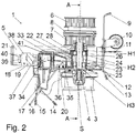
- FIGS. 1 to 3 show an inventive yarn feeding device 1 of a first example, which is used for feeding a yarn 2 to a textile machine, in particular a circular knitting machine.
- the yarn feeding device 1 has a yarn feed wheel 3 and a drive shaft 4.
- the yarn feed wheel 3 is attached to the textile machine so that the drive shaft 4, ie its axis of rotation, extends vertically.
- the yarn feed wheel 3 is arranged on the drive shaft 4.
- the yarn feeding device 1 comprises a carrier 5 for supporting the drive shaft 4 and for fastening the yarn feeding device 1 to the textile machine.
- the yarn feed wheel 3 is attached to the lower end of the drive shaft 4 with a screw S.
- At the upper end of the drive shaft 4 at least one, preferably a plurality of pulleys 6, 7 are provided. Between the pulleys 6, 7 there is at least one clutch disc 8 or other coupling means.
- the pulleys 6, 7 are rotatably mounted on the drive shaft 4 and rotatably coupled via the clutch disc 8 or the other coupling means, if necessary, with the drive shaft 4.
- the yarn feeding device 1 has on one side and in the inlet region of the thread 2, in the FIGS. 1 and 2 on the right side, Fadenleitopathy namely an inlet eye 9, a thread brake 10, a knot catcher 11, an inlet sensor 12 and another thread eye 13, the thread 2, as in FIG. 1 shown, in this order before the yarn feed wheel 3 passes.
- the yarn feeding device 1 in the yarn path after the yarn feed wheel 3 more yarn guide elements, namely successively a first outlet eye 14, a second outlet eye 15 and a discharge sensor 16.
- the yarn feeding device 1 is provided with a signaling device 17 and with a fastening device 18, to which the yarn feeding device 1 on a machine part of the knitting machine, in particular on a machine ring 19 a circular knitting machine, can be fastened.
- the carrier 5 of the yarn feeding device 1 is formed from a segment of an extruded profile.
- the carrier 5 forms at least one outer wall of the housing of the yarn feeding device 1.
- the yarn feeding device 1 has housing elements 20, 21, which are fastened to the carrier 5 and form outer walls of the housing.
- the carrier 5 is formed as a segment of an extruded profile whose cross-sectional planes extend parallel to the drive shaft 4 and perpendicular to the longitudinal direction of an elongated housing of the yarn feeding device 1.
- the carrier 5 forms a ceiling and two longitudinal side walls.
- FIGS. 1 and 2 extends the extrusion direction of the extruded profile in the horizontal direction, wherein the carrier 5 formed from a segment of the extruded profile with the housing elements 20, 21 forms an elongated, cuboid housing of the yarn feeding device 1.
- the shape of the cross-section of the extruded profile corresponds approximately to a rotated by 180 ° U, the bottom of the U's a ceiling and the two legs of the U's two Form longitudinal side walls of the housing.
- the carrier 5 thus forms the outer walls of the housing designed as a cover and as longitudinal side walls of the housing.
- the first housing member 20 forms a bottom and a front transverse side wall on the inlet side of the yarn feeding device 1 and the second housing member 21 is a rear transverse side wall of the housing of the yarn feeding device 1 opposite the front transverse side wall.
- the housing of the yarn feeding device 1 is formed from the outer walls of the carrier 5 and the housing elements 20, 21.
- the segment of the extruded profile and thus the carrier 5 can also be referred to as a chassis of the yarn feeding device 1.
- the longitudinal side walls of the carrier 5 in the lower region are slightly curved inwards so that the cross section of the housing approximately has the shape of a large omega " ⁇ " ( FIG. 3 ).
- the extruded profile is made of aluminum. At least the outer surfaces of the extruded profile forming the cover and the longitudinal side walls of the housing are made of anodized aluminum. For this purpose, the strand of an extruded profile is made anodized as a whole. The cut surfaces of the segment 5 forming the carrier are covered by the housing elements 20, 21.
- the yarn feed wheel 3 is disposed below the housing, below the first housing element 20.
- the yarn feeding device 1 is provided with additional elements.
- a first additional element is arranged, which is designed as a thread supply wheel 3 covering, bell-shaped wheel cover R.
- the first additional element is molded to the first housing member 20, i. the first additional element and the first housing element 20 are formed as one part.
- the drive shaft 4 is mounted in the housing formed by the carrier 5 and the housing elements 20, 21, the drive shaft 4 is mounted.
- the drive shaft 4 extends in the half of the inlet side vertically through the housing.
- the fastening device 18 and the signaling device 17 are located on the opposite side of the drive shaft 4, in the FIGS. 1 and 2 on the left.
- the signaling device 17 is arranged between the yarn feed wheel 3 and the fastening device 18.
- the bearing holder 22 For storage of the drive shaft 4, a separate bearing holder 22 is attached to the carrier 5.
- the bearing holder 22 has two undivided bearing seats 23, 24, namely a lower one Bearing seat 23 in a lower portion of the bearing holder 22 and an upper bearing seat 24 in an upper portion.
- a lower roller bearing 25 and in the upper bearing seat 24, an upper roller bearing 26 is arranged in the lower bearing seat 23, a lower roller bearing 25 and in the upper bearing seat 24, an upper roller bearing 26 is arranged.
- three hollow cylinders H1, H2, H3 are arranged, wherein the first hollow cylinder H1 between a not shown bearing seat of the lower pulley 7 and the upper bearing seat 24, the second hollow cylinder H2 between the two bearing seats 23 and 24 and the third hollow cylinder H3 between the lower bearing seat 23 and the yarn feed wheel 3 extend.
- the yarn feeding device 1 has at least one elastic compensating element, which is designed as a holder crimping element 27 and is arranged between the bearing holder 22 and the carrier 5.
- a bearing crimping element 28 is additionally arranged.
- the bearing holder 22 is formed of plastic.
- the lower bearing seat 23 of the bearing holder 22 is formed by pouring the lower rolling bearing 25.
- the bearing holder 22 is locked at two locations, in its upper portion with the upper bearing seat 24 and in its lower portion with the lower bearing seat 23 on the carrier 5.
- the bearing holder 22 is fixed in its upper portion to the carrier 5, for example by screws and locked in its lower portion by clamping connections to the carrier 5.
- the bearing holder 22 has a cylindrical body in which the two bearing seats 23, 24 are formed and whose, in the Figures 2 and 3 facing upward, end face is flat.
- the Halterquetschelement 27 is also formed, at least partially, as a cylindrical body which, if necessary, with tension, on the cylinder body of the bearing holder 22 can be placed.
- An upper end face of the Garrquetschieris 27 is aligned in the mounted state with the bearing holder 22.
- a circular recess 29 is provided, in which the Garrquetschettis 27 and the bearing holder 22 protrude with their faces and on whose inner surface they rest.
- the bearing holder 22 and the Halterquetschelement 27 are individually or jointly, for example by screws, attached to the ceiling or to the false ceiling of the carrier 5.
- the bearing holder 22 is in its lower portion in the figures with two opposing tabs 30 with a e.g. semicircular cross-section, provided.
- the Halterquetschelement 27 has the tabs 30 corresponding to the tabs 30 at least partially enclosing extensions 31.
- the tabs 30 and the enveloping extensions 31 protrude into corresponding side recesses 32 in the legs of the carrier 5, which form the longitudinal side walls of the housing.
- the tabs 30 and the enveloping extensions 31 form with the side recesses clamping connections, by which the bearing holder 22 is locked in its lower portion on the carrier 5.
- the arrangement of the end faces of the bearing holder 22 and the Halterquetschelements 27 in the upper circular recess 29 allows an upper locking and an upper adjustment of the bearing holder 22 with respect to the carrier 5.
- the arrangement of the tabs 30 and extensions 31 in the lower side recesses 32 allow one of the lower Locking and a lower adjustment.
- the holder crimping element 27 bridges possibly occurring production tolerances between the continuous casting profile of the carrier 5 and the bearing holder 22 made of plastic, in particular as an injection molded part.
- the bearing holder 22 is formed in this example as a part, as a one-piece injection molded part, together with a second additional element.
- This second additional element is designed as a cover 33. It forms, together with the first housing element 20, an interior space for accommodating an electronic assembly 34 as well as switching elements 35 and suspensions 36 for the inlet sensor 12 and the outlet sensor 14.
- the cover element 33 has the shape of a bottomless cuboid, the bottom passing through the first housing element 20 is formed. In a not shown on the machine ring 19 guided cable open two connected to the electrical assembly 34 pins 37th
- the fastening device 18 is formed by in the outlet region of the yarn feeding device 1, aligned openings 38 in the legs of the carrier 5. It has a threaded plate 39 extending between the legs and a screw 40.
- the extruded profile of the carrier 5 has an intermediate ceiling 41, which extends below the outer wall forming the ceiling of the housing. This false ceiling 41 gives the yarn feeding device 1 a higher stability.
- the arranged in the inlet region Fadenleit implant 9, 10, 11, 12, 13 are arranged on a holder 42 which is fastened by screws 43 on the housing of the yarn feeding device ( FIG. 1 ).
- the extruded profile of the carrier 5 is formed without this false ceiling.
- the bearing holder has at least two regions made of plastics of different elasticity.
- the alternative bearing holder is formed as a part that includes the functions of the bearing holder 22, the holder crimping member 27, and the bearing crimping member 28.
- a cylindrical inner first region made of a hard plastic, which has the shape of the bearing holder 22, an outer, second region of a softer plastic of greater elasticity in the form of Garrquetschieris 27 is formed.
- an inner, third region made of a plastic of an elasticity between that of the first and the second region, possibly in the form of Lagerquetschelements 28 is optionally formed.
- the area corresponding to the lower bearing seat 23 is optionally formed as in Example 1 by pouring the lower roller bearing 25.
- the plastic of the third region may also be that of the first region.
- FIGS. 4 to 10 An inventive yarn feeding device 50 of a second example is in the FIGS. 4 to 10 shown.
- the yarn feeding apparatus 50 of the second example is the same as that of the first example except for the differences explained in the following description. Corresponding elements are provided with the same reference numerals.
- the carrier 51 of the yarn feeding device 50 of the second example is also i. as the carrier 5 of the first example as a segment of a strand profile, namely an extruded aluminum.
- the cross-sectional planes of the segment of the extruded profile run parallel to the drive shaft 4 and the longitudinal direction of the extruded profile extends in the direction of the thread pattern of the yarn feeding device 50.
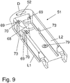
- the carrier 51 forms outer walls, likewise a cover D and two longitudinal side walls L1 and L2, of a housing of the yarn feeding device 50 (FIG. FIG. 9 ).
- the outer surfaces of the carrier 51 are provided with an applied by anodization layer.
- the shape of the cross section of the extruded profile and thus of the carrier 51 corresponds to that of the carrier 5 of the first example.
- the extruded profile of the carrier 51 also has an intermediate ceiling 52.
- the yarn feeding device 50 has three housing elements 53, 54, 55, wherein the first housing element 53 forms a front transverse side wall, the second housing element 54 forms a bottom and the third housing element 55 forms a rear transverse side wall opposite the front transverse side wall. That the housing of the yarn feeding device 50 is formed from the outer walls of the carrier 51 and the housing elements 53, 54, 55.
- the housing elements 53, 54, 55 are made of plastic.
- the yarn feeding device 50 is provided with additional elements ( FIG. 6 ).
- a first additional element is, similar to the first example, formed as a wheel cover R, which covers the yarn feed wheel 3 from above bell-shaped.
- the wheel cover R and the second housing member 54 are formed as a part, wherein the wheel cover R is integrally formed on the underside of the housing member 54.
- a second additional element is formed as an intermediate wall Z, which closes the interior of the housing to the region of the fastening device 18 with the openings 38.
- the intermediate wall Z and the second housing element 54 are formed as one part, wherein the intermediate wall Z is integrally formed on the upper side of the housing element 54.
- the housing member 54, the wheel cover R and the intermediate wall Z are made in one example as an injection molded part made of plastic.
- a third auxiliary element is formed as a separate cover member 56 which is secured to the second housing member 54.
- the cover 56 forms a seated on the housing member 54 and subsequent to the intermediate wall Z hood, between housing member 54 and cover 56, an interior is formed.
- an electronic assembly 34 and switching elements 35 and suspensions 36 for an inlet sensor 57 and an outlet sensor 58 are arranged.
- the in FIG. 2 shown thread pattern of the yarn feeding device 50 corresponds to that of the second example except for the arrangement of the suspensions 36 for the inlet sensor 57 and the outlet sensor 58.
- the inlet sensor 57 and the outlet sensor 58 have, like those of the first example, in the suspensions 36 mounted lever arms, the are each rotatable about a pivot axis arranged perpendicular to the axis of rotation.
- the suspension 35, and thus the pivot axis, of the inlet sensor 57 in the thread running direction behind the outlet sensor 58 is arranged.
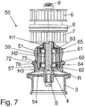
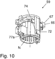
- the bearing holder 59 For storage of the drive shaft 4, a separate bearing holder 59 made of plastic is attached to the carrier 51.
- the bearing holder 59 has two sections, each with an undivided bearing seat 60, 61.
- a rolling bearing 62, 63 and between the bearing seat and the rolling bearing 62, 63, a bearing crimping element 64, 65 are arranged.
- the bearing holder 59 has a cylindrical body in which the bearing seats 60, 61 are formed.
- the bearing holder 59 is provided with a cylindrical opening, wherein the bearing seats 60, 61 are each formed by a stepped constriction of the opening.
- the bearing holder 59 thereby has in its central region a smaller inner diameter than in the two outer regions, namely in the figures lower portion with the lower bearing seat 60, the Lagerquetschelement 64 and the rolling bearing 62 and the upper region with the upper bearing seat 61, the bearing crimping element 65 and the rolling bearing 63 (FIG. FIG. 7 ).
- the bearing holder 59 is locked in its upper portion and in its lower portion on the carrier 51.
- the bearing holder 59 in the upper portion of two molded sleeve holder with two screw sleeves 66, the end surfaces 67 lie in a plane which is disposed below the end face of the cylindrical body of the bearing holder 59.
- One of the sleeve holders is arranged in the front region of the bearing holder 59 and the other in the rear region.
- the carrier 51 is provided in the region of the bearing holder 59 with an opening 68 through which the cylindrical body of the bearing holder 59 projects.
- the false ceiling 52 of the carrier 51 is provided with recesses, which lie in a plane bearing surfaces 69 for the Form end surfaces 67 of the screw sleeves 66. In the center of each of the bearing surfaces 69, a threaded hole 70 begins in the false ceiling 52.
- the bearing holder 59 is fixed to the carrier 51 by screws 71, which project through the screw sleeves 66 of the bearing holder 59 in the threaded holes 70 of the false ceiling 52 of the carrier 51. The position of the bearing holder 59 is adjusted by the end faces 67 and the bearing surfaces 69.
- bearing holder clamping elements 72 For the lower locking of the bearing holder 59 has two molded, protruding from the bearing holder clamping elements 72 which are arranged on opposite sides in the region of the longitudinal side walls of the carrier 51.
- the clamping members 72 of the one, lower portion taper towards the other, upper portion of the bearing holder 59, i. the clamping elements taper upwards. They are designed as projecting trapezoids whose shorter parallel sides are arranged at the top.
- the longitudinal side walls of the carrier 51 have the clamping elements 72 corresponding recesses 73.
- the recesses 73 taper upwards. They are trapezoidal.
- the clamp connection is automatically generated when mounting the bearing holder 59 on the false ceiling 52. She adjusts the storekeeper in the lower section.
- the clamping connection prevents twisting or tilting of the bearing holder, in particular in the longitudinal direction of the yarn feeding device 50.
- the bearing holder 59 is locked by a further clamping connection to the carrier 51.
- the clamping connection is formed by in the region of the longitudinal side walls of the carrier 51 projecting wall portions 74 of its cylindrical body, which rest under tension on the inner sides of the longitudinal side walls of the carrier 51.
- the bearing holder 59 is formed without projecting wall portions 74.
- cover parts 75 for the clamping element 72 and molded on the second housing element 54 are designed as cover parts 75 for the clamping element 72 and molded on the second housing element 54.
- the cover members 75 extend tab-like over the clamping elements 72. They each have in their upper part a step 76, which forms a stop for a bracket of the inlet sensor 57 respectively.
- the second housing member 54 is fixed thereto by front and rear screws 77 which project into threaded holes 77a of the bearing holder 59 and fixed to the bracket 51 by a screw 78 in the intermediate wall Z projecting into a threaded hole 79 of the bracket 51.
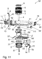
- a yarn feeding device 50 'of an alternative of the second example is in the exploded view FIG. 11 shown.
- the inlet side of the yarn feeding device 50 ' is on the left side of FIG. 11 shown.
- the yarn feeding device 50 ' corresponds to the yarn feeding device 50 except for differences explained in the following description. Corresponding elements are provided with the same reference numerals.
- the exploded view shows the drive shaft 4 of the yarn feeding device 50 ', at the upper end of two pulleys 6, 7 are provided. Between the pulleys 6, 7 is a clutch disc 9. Compared to the yarn feeding device 50, the yarn feeding device 50 'in addition to a cover A above the upper clutch disc 6.
- the drive shaft 4 extends vertically through the carrier 51. At the lower end of the drive shaft 4, a yarn feed wheel 3 'with a screw S and a disc S is attached.
- the yarn feed wheel 3 ' has, in contrast to the yarn feed wheel 3 of the yarn feeding device 50 on a rod cage.
- FIG. 11 shows the hollow cylinder H1, the bearing holder 59 and the hollow cylinder H3, which are arranged on the drive shaft 4.
- the inlet eye 9, the knot catcher 11, the thread brake 10 and the thread eye 13 are arranged on the holder 42.
- the yarn feeding device 50 of the knot catcher 11 is arranged in the yarn path in front of the yarn brake 10. It is secured by an additional screw 11 'on the holder 42.
- the holder 42 is fastened by two screws 43 on the housing of the yarn feeding device 50 '.
- a screw 43 simultaneously fastens the thread brake 10 on the holder 42nd
- the bearing holder 59 is fixed to the bracket 51 by four screws 71.
- the holder 42 is attached to the bearing holder 59 and with this on the carrier 51.
- the upper screw 43 is connected to an element St, a nut, and the lower screw to the bearing holder 59 itself.
- the yarn feeding device 50 ' like the yarn feeding device 50, has three housing elements 53', 54 ', and 55'.
- the first housing element 53 ' forms a front transverse side wall and a subsequent bottom part of the housing of the yarn feeding device 50'.
- the second housing element 54 ' forms a further, larger bottom part of the housing.
- the third housing element 55 ' forms a rear, the front transverse side wall opposite transverse side wall.
- the third housing element 55 ' is located in the region of the fastening device 18.
- a U-shaped threaded plate 39' is set in the opening 38 against the housing element 55 'and connected by a clamping connection with the housing element 55'.
- the housing element 54 ' is made with the two additional elements wheel cover R and partition Z' as a part, namely as an injection molded part made of plastic.
- the third additional element namely the separate cover element 56 ', is fastened to the housing element 54'.
- the cover 56 ' is connected to the housing member 54' by clamping connections.
- the housing element 54 'with the intermediate wall Z' forms an interior together with the cover element 56 '.
- housing element 54 ' with the two additional elements and the cover 56' form an assembly.
- the assembly also includes the inlet sensor 57 and the outlet sensor 58.
- the electronics assembly 34 e.g. arranged with line elements and switching elements 35 and the suspensions for the inlet sensor 57 and the outlet sensor 58.
- the assembly is attached to the carrier 51.
- the assembly is secured together with the signaling device 17 via the screw 78 on the carrier 51.
- the assembly is also secured to the bearing support 59 with screws 77 and secured to the support 51 via the bearing support 57.
- Assemblies can be prefabricated at various locations and delivered to final assembly to a different location.
- sensitive components can be prefabricated in assemblies with an interior and sent securely.
- the prefabricated assembly can be shipped for final assembly.
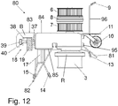
- An inventive yarn feeding device 80 of a third example is in the FIGS. 12 to 14 shown.
- the yarn feeding apparatus 80 of the third example is the same as that of the first example except for the following differences.
- Corresponding elements are identified by the same reference numerals.
- the yarn feeding device 80 is shown without a thread, wherein the inlet sensor 81 and the outlet sensor 82 are in rest positions.
- the knot catcher 11 is arranged in the thread path in front of the brake 10.
- the outlet sensor 82 is arranged in the thread path between the first outlet eye 14 and the second outlet eye 15.
- the carrier 83 is formed as a segment of an extruded aluminum profile.
- the extrusion direction of the extruded profile extends in the horizontal direction perpendicular to the drive shaft 4 and, unlike the first example, perpendicular to the planes in which the thread is guided in the inlet region and in the outlet region by the thread guide elements, i. perpendicular to the thread path to the textile machine.
- the extrusion direction of the extruded profile of the carrier 83 extends perpendicular to that of the first and second examples.
- Housing elements of the yarn feeding device 80 of the third example are formed as a cover 84 and a cover 85.
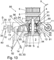
- the cross section of the extruded profile, from the segments of which the carrier 83 of the third example is made, has substantially the shape of a "P" rotated by 90 ° in the clockwise direction. That is the in FIG. 13 shown carrier has a horizontal beam portion, at the in FIG. 13 right side of a frame portion is formed, which has an approximately square cross-section.
- the cross section is rectangular, oval or round.
- the carrier 83 has a recess extending in the longitudinal direction of the extruded profile which forms the opening 38 for the fastening device 18.
- a threaded plate 39 is arranged with the fastening screw 40.
- the cover element 84 designed as a housing element has a ceiling, two longitudinal side walls and a front transverse side wall.
- the cover 84 extends in the horizontal direction until the attachment part of the beam portion.
- the cover 84 covers outer surfaces of the carrier 83, namely up to the attachment part B, an upper side of the beam section with its ceiling, the front transverse side wall with its transverse side wall and the cut surfaces of the carrier 83 on the longitudinal sides with their longitudinal side walls.
- the fastening part B of the carrier 83 projects out of the cover 84.
- a housing of the yarn feeding device 80 is formed by the carrier 83, whose outer walls are covered by the cover 84, the cover 84 and the cover plate 85 with the intermediate wall Z.
- a separate additional element is designed as a wheel cover R for the yarn feed wheel 3 and attached to the carrier 83.
- the cover bottom 85 with the intermediate wall Z and the cover 84 are each formed as one-piece injection molded plastic parts.
- the drive shaft 4 is arranged in the frame portion of the carrier 83, in which it is supported by means of a bearing holder 86.
- the separate bearing holder 86 has a lower and an upper portion each with a bearing seat 87, 88, in each of which a roller bearing 89, 90 is arranged.
- the bearing holder 86 is formed of plastic.
- the lower bearing seat 87 is formed by pouring the rolling bearing 89.
- a bearing crimping member 91 is disposed between the upper bearing seat 88 and the upper roller bearing 90.
- the bearing holder 86 is locked in the upper portion and in the lower portion of the carrier.
- the bearing holder 86 in the upper and in the lower portion projections 92 which protrude into corresponding recesses 93 of the frame portion of the carrier 83.
- the projections 92 and the recesses 93 extend parallel to the longitudinal direction of the extruded profile, so that the bearing holder 83 can be inserted in this direction in the frame of the frame part.
- the bearing retainer 86 is provided with upper and lower locking means 94, e.g. Clamping bolts and / or screws in both sections locked to the carrier 83.
- FIG. 13 also shows screws 95, through which a holder 96 and the cover 84 are fixed to the carrier 83 on the front transverse side. On the holder 96, the inlet eye 9 and the thread eye 13 are formed and the knot catcher 11 and the thread brake 10 is attached.
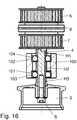
- the carrier 100 is also formed as a segment of an extruded aluminum profile.
- the extrusion direction of the extruded profile runs parallel to the drive shaft 4 and thus perpendicular to the longitudinal direction of the housing of the yarn feeding device, which corresponds to the running direction of the yarn to the textile machine.
- the cross-section of the extruded profile is in the form of an elongate, internally open oval having at one end an annular surface and at a distance from the annular surface at the other end a filled portion.
- a segment of the extruded profile, and thus the support 100, is thereby formed in its front portion as a cylinder Y for supporting the drive shaft 4 and in its rear portion of solid material in which the opening 38 is provided for the fastening device 18, e.g. is milled out.
- In its central portion between the front and rear portions of the carrier 100 defines a housing interior.
- the carrier 100 forms outer walls of the housing of the yarn feeding device, namely the two longitudinal side walls and the front and rear transverse side wall.
- Housing elements not shown form a ceiling and a bottom of the housing of the yarn feeding device.
- two storage holders are formed in the carrier 100. That the carrier 100 forms the storekeeper itself.
- a lower bearing seat 101 is formed in a lower portion of the cylinder Y, and an upper bearing seat 102 is formed in an upper portion, respectively, as a stepped extension of the cylinder Y downward and upward.
- the bearing seats 101, 102 each have a rolling bearing 103, 104 are arranged. Between the rolling bearings 103, 104 and the respective bearing seats 101, 102 Lagerquetschieri not shown are provided.
Landscapes
- Engineering & Computer Science (AREA)
- Textile Engineering (AREA)
- Knitting Machines (AREA)
- Looms (AREA)
- Injection Moulding Of Plastics Or The Like (AREA)
- Tyre Moulding (AREA)
- Ropes Or Cables (AREA)
- Rolling Contact Bearings (AREA)
- Yarns And Mechanical Finishing Of Yarns Or Ropes (AREA)
Claims (14)
- Fournisseur de fil (1, 50, 50', 80) pour fournir un fil à une machine textile
avec une roue de délivreur de fil (3),
avec un arbre moteur (4) sur lequel est agencée la roue de délivreur de fil (3), avec un support (5, 51, 83, 100) avec au moins un appui de palier (22, 59, 86) avec au moins un siège de palier non divisé (23, 24 ; 60, 61 ; 87, 88 ; 101, 102) destiné à recevoir un palier à roulement (25, 26) à chaque fois et avec au moins un palier à roulement (25, 26 ; 62, 63 ; 89, 90 ; 103, 104) destiné à loger l'arbre moteur (4),
dans lequel le fournisseur de fil (1, 50, 50', 80) présente au moins un élément de carter (20, 21 ; 53, 54, 55 ; 53', 54', 55' ; 84, 85) qui est fixé au support et forme une paroi extérieure du carter du fournisseur de fil (1, 50, 80) et
dans lequel le fournisseur de fil (1, 50, 50', 80) présente au moins un élément supplémentaire (R, 33, 56, 56', Z, Z') qui est agencé sur le support (5) ou sur l'élément de carter (20 ; 54, 54', 85) ou sur l'appui de palier (22),
dans lequel le ou l'un des éléments de carter (20, 54, 54', 85) et le ou l'un des éléments supplémentaires (33, 56, 56', Z, Z') qui est fixé à l'élément de carter (20, 54, 54', Z, Z') forment un espace intérieur, caractérisé en ce que le support (5, 51, 83, 100) est formé d'au moins un segment tronçonné d'un profil extrudé. - Fournisseur de fil (1, 50, 50', 80) selon la revendication 1, caractérisé en ce que le support (5, 51, 83, 100) est réalisé comme au moins un segment d'un profil extrudé en aluminium.
- Fournisseur de fil (1, 50, 50') selon la revendication 1 ou 2, caractérisé en ce que le support (5, 51, 100) forme au moins une paroi extérieure d'un carter du fournisseur de fil (1, 50).
- Fournisseur de fil (1, 50, 50', 80) selon la revendication 3, caractérisé en ce que le ou un des éléments supplémentaires est réalisé comme un chapeau de roue (R) ou comme un élément de recouvrement (33, 56, 56') ou comme une paroi intermédiaire (Z, Z').
- Fournisseur de fil (1, 50, 50', 80) selon la revendication 4, caractérisé en ce que le ou l'un des éléments de carter (20, 54, 54', 85) est réalisé avec au moins un autre élément de carter et/ou avec au moins un élément supplémentaire (R) en tant qu'une partie.
- Fournisseur de fil (1, 50, 50', 80) selon l'une quelconque des revendications 1 à 5, caractérisé en ce qu'un élément de carter (20, 54, 54', 85) et au moins un élément supplémentaire séparé (56, 56', Z, Z') fixé à l'élément de carter (20, 54, 54', 85) forment un ensemble.
- Fournisseur de fil (1, 50, 50', 80) selon l'une quelconque des revendications 1 à 6, caractérisé en ce qu'au moins un appui de palier dans le support (100) est réalisé par le support (100).
- Fournisseur de fil (1, 50, 50', 80) selon l'une quelconque des revendications 1 à 7, caractérisé en ce qu'au moins un appui de palier est réalisé comme un appui de palier séparé (22, 59, 86) qui est fixé au support (5, 51, 83).
- Fournisseur de fil (1, 50, 50', 80) selon la revendication 8, caractérisé en ce que l'appui de palier (22, 59, 86, 100) présente deux sections avec chacune un siège de palier (23, 24 ; 60, 61 ; 87, 88 ; 101, 102).
- Fournisseur de fil (1, 50, 50') selon l'une quelconque des revendications 1 à 9, caractérisé en ce que le support (5, 51) est formé d'un segment d'un profil extrudé dont des plans de section transversale s'étendent parallèlement à l'arbre moteur (4) perpendiculairement à la direction longitudinale du fournisseur de fil (1, 50), dans lequel le support (5, 51) forme un plafond et/ou un plancher et deux parois latérales longitudinales d'un carter du fournisseur de fil (1, 50).
- Fournisseur de fil (1) selon la revendication 10, caractérisé en ce que le support (5, 51) forme un plafond, au-dessous du plafond un plafond intermédiaire (41, 52) et deux parois latérales longitudinales du carter du fournisseur de fil (1).
- Fournisseur de fil (1) selon la revendication 11, caractérisé en ce que l'appui de palier (22, 59) présente deux sections avec chacune un siège de palier (23, 24, 60, 61) et est fixé dans une section au plafond intermédiaire (41, 52) et est bloqué par assemblages serrés dans l'autre section au niveau des parois latérales longitudinales.
- Fournisseur de fil (80) selon l'une quelconque des revendications 1 à 9, caractérisé en ce que le support (83) est formé d'un profil extrudé dont des plans de section transversale s'étendent parallèlement à l'arbre moteur (4) et parallèlement à la direction longitudinale du fournisseur de fil (80), dans lequel le support (83) forme un plafond, un plancher et deux parois latérales transversales d'un carter du fournisseur de fil (80).
- Fournisseur de fil selon l'une quelconque des revendications 1 à 9, caractérisé en ce que le support (100) est formé d'un profil extrudé dont des plans de section transversale s'étendent perpendiculairement à l'arbre moteur (4), dans lequel le support (100) forme deux parois latérales longitudinales et deux parois latérales transversales d'un carter du fournisseur de fil.
Priority Applications (1)
| Application Number | Priority Date | Filing Date | Title |
|---|---|---|---|
| EP16200694.4A EP3178979B1 (fr) | 2012-06-08 | 2013-06-07 | Délivreur pour appel de fil |
Applications Claiming Priority (2)
| Application Number | Priority Date | Filing Date | Title |
|---|---|---|---|
| DE102012104976.9A DE102012104976B4 (de) | 2012-06-08 | 2012-06-08 | Fadenliefergerät |
| PCT/EP2013/061828 WO2013182690A1 (fr) | 2012-06-08 | 2013-06-07 | Distributeur de fil |
Related Child Applications (2)
| Application Number | Title | Priority Date | Filing Date |
|---|---|---|---|
| EP16200694.4A Division EP3178979B1 (fr) | 2012-06-08 | 2013-06-07 | Délivreur pour appel de fil |
| EP16200694.4A Division-Into EP3178979B1 (fr) | 2012-06-08 | 2013-06-07 | Délivreur pour appel de fil |
Publications (2)
| Publication Number | Publication Date |
|---|---|
| EP2859140A1 EP2859140A1 (fr) | 2015-04-15 |
| EP2859140B1 true EP2859140B1 (fr) | 2019-08-07 |
Family
ID=48607248
Family Applications (2)
| Application Number | Title | Priority Date | Filing Date |
|---|---|---|---|
| EP16200694.4A Active EP3178979B1 (fr) | 2012-06-08 | 2013-06-07 | Délivreur pour appel de fil |
| EP13728167.1A Active EP2859140B1 (fr) | 2012-06-08 | 2013-06-07 | Distributeur de fil |
Family Applications Before (1)
| Application Number | Title | Priority Date | Filing Date |
|---|---|---|---|
| EP16200694.4A Active EP3178979B1 (fr) | 2012-06-08 | 2013-06-07 | Délivreur pour appel de fil |
Country Status (8)
| Country | Link |
|---|---|
| EP (2) | EP3178979B1 (fr) |
| CN (2) | CN104520482B (fr) |
| BR (2) | BR112014030508A2 (fr) |
| DE (1) | DE102012104976B4 (fr) |
| IN (1) | IN2014DN10356A (fr) |
| TR (1) | TR201904060T4 (fr) |
| TW (2) | TWI557284B (fr) |
| WO (1) | WO2013182690A1 (fr) |
Families Citing this family (1)
| Publication number | Priority date | Publication date | Assignee | Title |
|---|---|---|---|---|
| CN114738380A (zh) * | 2021-01-07 | 2022-07-12 | 斯凯孚公司 | 滚针轴承 |
Family Cites Families (12)
| Publication number | Priority date | Publication date | Assignee | Title |
|---|---|---|---|---|
| IT212037Z2 (it) * | 1987-10-12 | 1989-05-25 | Roy Electrotex Spa | Carcassa perfezionata per alimentatori di trama. |
| US5156079A (en) * | 1990-06-05 | 1992-10-20 | North Carolina State University | Yarn carrier apparatus for braiding machines and the like |
| DE4409450C2 (de) * | 1994-03-18 | 1996-12-05 | Memminger Iro Gmbh | Fadenbremseinrichtung |
| DE19932485A1 (de) * | 1999-07-12 | 2001-01-18 | Memminger Iro Gmbh | Lagereinrichtung, insbesondere für Fadenliefergeräte |
| DE19932481A1 (de) * | 1999-07-12 | 2001-01-18 | Memminger Iro Gmbh | Fadenliefergerät für Textilmaschinen |
| CN2387122Y (zh) * | 1999-07-21 | 2000-07-12 | 林忠民 | 针织机喂纱器改良装置 |
| CZ291398B6 (cs) * | 2000-12-29 | 2003-02-12 | Amtek, Spol. S R. O. | Okrouhlý pletací stroj |
| CN1366104A (zh) * | 2001-01-14 | 2002-08-28 | 叶齐炎 | 位移式输纱装置和输纱方法 |
| SE0301181D0 (sv) * | 2003-04-21 | 2003-04-21 | Iropa Ag | Yarn Feeder and Reflector body |
| WO2007042057A1 (fr) * | 2005-10-07 | 2007-04-19 | Memminger-Iro Gmbh | Distributeur de fil à roue amovible |
| CN101535543B (zh) * | 2006-10-06 | 2011-07-27 | 梅明格-Iro股份有限公司 | 喂纱器 |
| CN101209465A (zh) * | 2006-12-26 | 2008-07-02 | 环麒钢铝合金股份有限公司 | 制备铝系复合材料的挤制型材的方法和挤制型材 |
-
2012
- 2012-06-08 DE DE102012104976.9A patent/DE102012104976B4/de not_active Expired - Fee Related
-
2013
- 2013-06-07 BR BR112014030508A patent/BR112014030508A2/pt not_active Application Discontinuation
- 2013-06-07 WO PCT/EP2013/061828 patent/WO2013182690A1/fr unknown
- 2013-06-07 IN IN10356DEN2014 patent/IN2014DN10356A/en unknown
- 2013-06-07 TR TR2019/04060T patent/TR201904060T4/tr unknown
- 2013-06-07 CN CN201380042079.8A patent/CN104520482B/zh active Active
- 2013-06-07 BR BR122017012186A patent/BR122017012186A2/pt not_active Application Discontinuation
- 2013-06-07 EP EP16200694.4A patent/EP3178979B1/fr active Active
- 2013-06-07 EP EP13728167.1A patent/EP2859140B1/fr active Active
- 2013-06-07 TW TW102120237A patent/TWI557284B/zh active
- 2013-06-07 TW TW105131108A patent/TWI588311B/zh active
- 2013-06-07 CN CN201610883196.2A patent/CN106987997B/zh active Active
Non-Patent Citations (1)
| Title |
|---|
| None * |
Also Published As
| Publication number | Publication date |
|---|---|
| TW201704579A (zh) | 2017-02-01 |
| TW201410931A (zh) | 2014-03-16 |
| WO2013182690A1 (fr) | 2013-12-12 |
| TR201904060T4 (tr) | 2019-04-22 |
| TWI588311B (zh) | 2017-06-21 |
| EP3178979B1 (fr) | 2018-12-26 |
| DE102012104976A1 (de) | 2013-12-12 |
| CN106987997B (zh) | 2020-03-03 |
| BR122017012186A2 (pt) | 2019-09-03 |
| EP3178979A1 (fr) | 2017-06-14 |
| TWI557284B (zh) | 2016-11-11 |
| CN104520482A (zh) | 2015-04-15 |
| IN2014DN10356A (fr) | 2015-08-07 |
| DE102012104976B4 (de) | 2015-11-05 |
| BR112014030508A2 (pt) | 2017-06-27 |
| CN106987997A (zh) | 2017-07-28 |
| EP2859140A1 (fr) | 2015-04-15 |
| CN104520482B (zh) | 2017-02-15 |
Similar Documents
| Publication | Publication Date | Title |
|---|---|---|
| DE69307075T2 (de) | Führung für zylindrische Teleskopteile und eine Säule, die solche Führungen enthält | |
| DE19955755C2 (de) | Kraftfahrzeug mit einer Verstärkungsstruktur eines Seitenlängsträgerteils | |
| DE2533019A1 (de) | Lagerhalterung | |
| EP2859140B1 (fr) | Distributeur de fil | |
| EP2358931B1 (fr) | Cylindre supérieur pour un banc d'étirage | |
| DE60219440T2 (de) | Einer vorrichtung zur herstellung von käfigen zugeordnetes bildungselement | |
| DE3301309A1 (de) | Verstellvorrichtung fuer fahrzeug-sitze | |
| EP2805083B1 (fr) | Connexion de câble et manchon de câble pour une connexion de câble | |
| DE4023426A1 (de) | Trittleiter | |
| WO2021198282A1 (fr) | Dispositif de fixation conçu pour fixer un entraînement d'une installation d'ascenseur | |
| EP1525063B1 (fr) | Procede de fixation du tambour d'un lave-linge et fixation a cet effet | |
| DE102014117021B3 (de) | Gießdüse, Gießrad und Anordnung umfassend ein Gießrad und mindestens eine Gießdüse | |
| DE3619673C2 (fr) | ||
| EP3344478B1 (fr) | Support d'appui | |
| DE4203150A1 (de) | Dreheinrichtung fuer fahrzeugsitze, insbesondere kraftfahrzeugsitze | |
| DE102015206224A1 (de) | Wälzlagerkäfig | |
| DE3309676C1 (de) | Schwerthaltevorrichtung für Falzmaschinen | |
| DE102019008257B4 (de) | Modulare Halterungsvorrichtung zum Montieren eines Gegenstands an einem Fahrzeug, Halteranordnung und Fahrzeug umfassend solch eine Halteranordnung | |
| DE19852432C1 (de) | Ersatzrad-Tragvorrichtung für eine Ersatzradwinde | |
| DE29619925U1 (de) | Verbindungskonstruktion für Stehlampen | |
| EP0223938A1 (fr) | Magasin pour bande abrasive | |
| EP0768268B1 (fr) | Cantre, support pour une plaque intercalaire à l'intérieur du cantre et plaque intercalaire | |
| EP4091932A1 (fr) | Système de fixation destiné à la fixation d'éléments de revêtement dans un avion, en particulier pour la fixation de parois latérales et de panneaux dado | |
| WO1998001203A1 (fr) | Distributeur de liquide pour colonne echangeuse de substances | |
| EP4296444A2 (fr) | Dispositif de montage |
Legal Events
| Date | Code | Title | Description |
|---|---|---|---|
| PUAI | Public reference made under article 153(3) epc to a published international application that has entered the european phase |
Free format text: ORIGINAL CODE: 0009012 |
|
| 17P | Request for examination filed |
Effective date: 20141205 |
|
| AK | Designated contracting states |
Kind code of ref document: A1 Designated state(s): AL AT BE BG CH CY CZ DE DK EE ES FI FR GB GR HR HU IE IS IT LI LT LU LV MC MK MT NL NO PL PT RO RS SE SI SK SM TR |
|
| AX | Request for extension of the european patent |
Extension state: BA ME |
|
| DAX | Request for extension of the european patent (deleted) | ||
| STAA | Information on the status of an ep patent application or granted ep patent |
Free format text: STATUS: EXAMINATION IS IN PROGRESS |
|
| 17Q | First examination report despatched |
Effective date: 20170302 |
|
| GRAP | Despatch of communication of intention to grant a patent |
Free format text: ORIGINAL CODE: EPIDOSNIGR1 |
|
| STAA | Information on the status of an ep patent application or granted ep patent |
Free format text: STATUS: GRANT OF PATENT IS INTENDED |
|
| INTG | Intention to grant announced |
Effective date: 20181008 |
|
| GRAJ | Information related to disapproval of communication of intention to grant by the applicant or resumption of examination proceedings by the epo deleted |
Free format text: ORIGINAL CODE: EPIDOSDIGR1 |
|
| STAA | Information on the status of an ep patent application or granted ep patent |
Free format text: STATUS: EXAMINATION IS IN PROGRESS |
|
| INTC | Intention to grant announced (deleted) | ||
| GRAP | Despatch of communication of intention to grant a patent |
Free format text: ORIGINAL CODE: EPIDOSNIGR1 |
|
| STAA | Information on the status of an ep patent application or granted ep patent |
Free format text: STATUS: GRANT OF PATENT IS INTENDED |
|
| INTG | Intention to grant announced |
Effective date: 20190115 |
|
| GRAS | Grant fee paid |
Free format text: ORIGINAL CODE: EPIDOSNIGR3 |
|
| GRAA | (expected) grant |
Free format text: ORIGINAL CODE: 0009210 |
|
| STAA | Information on the status of an ep patent application or granted ep patent |
Free format text: STATUS: THE PATENT HAS BEEN GRANTED |
|
| AK | Designated contracting states |
Kind code of ref document: B1 Designated state(s): AL AT BE BG CH CY CZ DE DK EE ES FI FR GB GR HR HU IE IS IT LI LT LU LV MC MK MT NL NO PL PT RO RS SE SI SK SM TR |
|
| REG | Reference to a national code |
Ref country code: GB Ref legal event code: FG4D Free format text: NOT ENGLISH |
|
| REG | Reference to a national code |
Ref country code: CH Ref legal event code: EP Ref country code: AT Ref legal event code: REF Ref document number: 1164030 Country of ref document: AT Kind code of ref document: T Effective date: 20190815 |
|
| REG | Reference to a national code |
Ref country code: DE Ref legal event code: R096 Ref document number: 502013013317 Country of ref document: DE |
|
| REG | Reference to a national code |
Ref country code: IE Ref legal event code: FG4D Free format text: LANGUAGE OF EP DOCUMENT: GERMAN |
|
| REG | Reference to a national code |
Ref country code: NL Ref legal event code: MP Effective date: 20190807 |
|
| REG | Reference to a national code |
Ref country code: LT Ref legal event code: MG4D |
|
| PG25 | Lapsed in a contracting state [announced via postgrant information from national office to epo] |
Ref country code: SE Free format text: LAPSE BECAUSE OF FAILURE TO SUBMIT A TRANSLATION OF THE DESCRIPTION OR TO PAY THE FEE WITHIN THE PRESCRIBED TIME-LIMIT Effective date: 20190807 Ref country code: NL Free format text: LAPSE BECAUSE OF FAILURE TO SUBMIT A TRANSLATION OF THE DESCRIPTION OR TO PAY THE FEE WITHIN THE PRESCRIBED TIME-LIMIT Effective date: 20190807 Ref country code: BG Free format text: LAPSE BECAUSE OF FAILURE TO SUBMIT A TRANSLATION OF THE DESCRIPTION OR TO PAY THE FEE WITHIN THE PRESCRIBED TIME-LIMIT Effective date: 20191107 Ref country code: LT Free format text: LAPSE BECAUSE OF FAILURE TO SUBMIT A TRANSLATION OF THE DESCRIPTION OR TO PAY THE FEE WITHIN THE PRESCRIBED TIME-LIMIT Effective date: 20190807 Ref country code: HR Free format text: LAPSE BECAUSE OF FAILURE TO SUBMIT A TRANSLATION OF THE DESCRIPTION OR TO PAY THE FEE WITHIN THE PRESCRIBED TIME-LIMIT Effective date: 20190807 Ref country code: PT Free format text: LAPSE BECAUSE OF FAILURE TO SUBMIT A TRANSLATION OF THE DESCRIPTION OR TO PAY THE FEE WITHIN THE PRESCRIBED TIME-LIMIT Effective date: 20191209 Ref country code: FI Free format text: LAPSE BECAUSE OF FAILURE TO SUBMIT A TRANSLATION OF THE DESCRIPTION OR TO PAY THE FEE WITHIN THE PRESCRIBED TIME-LIMIT Effective date: 20190807 Ref country code: NO Free format text: LAPSE BECAUSE OF FAILURE TO SUBMIT A TRANSLATION OF THE DESCRIPTION OR TO PAY THE FEE WITHIN THE PRESCRIBED TIME-LIMIT Effective date: 20191107 |
|
| PG25 | Lapsed in a contracting state [announced via postgrant information from national office to epo] |
Ref country code: GR Free format text: LAPSE BECAUSE OF FAILURE TO SUBMIT A TRANSLATION OF THE DESCRIPTION OR TO PAY THE FEE WITHIN THE PRESCRIBED TIME-LIMIT Effective date: 20191108 Ref country code: LV Free format text: LAPSE BECAUSE OF FAILURE TO SUBMIT A TRANSLATION OF THE DESCRIPTION OR TO PAY THE FEE WITHIN THE PRESCRIBED TIME-LIMIT Effective date: 20190807 Ref country code: IS Free format text: LAPSE BECAUSE OF FAILURE TO SUBMIT A TRANSLATION OF THE DESCRIPTION OR TO PAY THE FEE WITHIN THE PRESCRIBED TIME-LIMIT Effective date: 20191207 Ref country code: ES Free format text: LAPSE BECAUSE OF FAILURE TO SUBMIT A TRANSLATION OF THE DESCRIPTION OR TO PAY THE FEE WITHIN THE PRESCRIBED TIME-LIMIT Effective date: 20190807 Ref country code: RS Free format text: LAPSE BECAUSE OF FAILURE TO SUBMIT A TRANSLATION OF THE DESCRIPTION OR TO PAY THE FEE WITHIN THE PRESCRIBED TIME-LIMIT Effective date: 20190807 Ref country code: AL Free format text: LAPSE BECAUSE OF FAILURE TO SUBMIT A TRANSLATION OF THE DESCRIPTION OR TO PAY THE FEE WITHIN THE PRESCRIBED TIME-LIMIT Effective date: 20190807 |
|
| PG25 | Lapsed in a contracting state [announced via postgrant information from national office to epo] |
Ref country code: DK Free format text: LAPSE BECAUSE OF FAILURE TO SUBMIT A TRANSLATION OF THE DESCRIPTION OR TO PAY THE FEE WITHIN THE PRESCRIBED TIME-LIMIT Effective date: 20190807 Ref country code: EE Free format text: LAPSE BECAUSE OF FAILURE TO SUBMIT A TRANSLATION OF THE DESCRIPTION OR TO PAY THE FEE WITHIN THE PRESCRIBED TIME-LIMIT Effective date: 20190807 Ref country code: RO Free format text: LAPSE BECAUSE OF FAILURE TO SUBMIT A TRANSLATION OF THE DESCRIPTION OR TO PAY THE FEE WITHIN THE PRESCRIBED TIME-LIMIT Effective date: 20190807 Ref country code: PL Free format text: LAPSE BECAUSE OF FAILURE TO SUBMIT A TRANSLATION OF THE DESCRIPTION OR TO PAY THE FEE WITHIN THE PRESCRIBED TIME-LIMIT Effective date: 20190807 |
|
| PG25 | Lapsed in a contracting state [announced via postgrant information from national office to epo] |
Ref country code: SM Free format text: LAPSE BECAUSE OF FAILURE TO SUBMIT A TRANSLATION OF THE DESCRIPTION OR TO PAY THE FEE WITHIN THE PRESCRIBED TIME-LIMIT Effective date: 20190807 Ref country code: SK Free format text: LAPSE BECAUSE OF FAILURE TO SUBMIT A TRANSLATION OF THE DESCRIPTION OR TO PAY THE FEE WITHIN THE PRESCRIBED TIME-LIMIT Effective date: 20190807 Ref country code: IS Free format text: LAPSE BECAUSE OF FAILURE TO SUBMIT A TRANSLATION OF THE DESCRIPTION OR TO PAY THE FEE WITHIN THE PRESCRIBED TIME-LIMIT Effective date: 20200224 Ref country code: CZ Free format text: LAPSE BECAUSE OF FAILURE TO SUBMIT A TRANSLATION OF THE DESCRIPTION OR TO PAY THE FEE WITHIN THE PRESCRIBED TIME-LIMIT Effective date: 20190807 |
|
| REG | Reference to a national code |
Ref country code: DE Ref legal event code: R097 Ref document number: 502013013317 Country of ref document: DE |
|
| PLBE | No opposition filed within time limit |
Free format text: ORIGINAL CODE: 0009261 |
|
| STAA | Information on the status of an ep patent application or granted ep patent |
Free format text: STATUS: NO OPPOSITION FILED WITHIN TIME LIMIT |
|
| PG2D | Information on lapse in contracting state deleted |
Ref country code: IS |
|
| 26N | No opposition filed |
Effective date: 20200603 |
|
| PG25 | Lapsed in a contracting state [announced via postgrant information from national office to epo] |
Ref country code: SI Free format text: LAPSE BECAUSE OF FAILURE TO SUBMIT A TRANSLATION OF THE DESCRIPTION OR TO PAY THE FEE WITHIN THE PRESCRIBED TIME-LIMIT Effective date: 20190807 |
|
| PGFP | Annual fee paid to national office [announced via postgrant information from national office to epo] |
Ref country code: IT Payment date: 20200630 Year of fee payment: 8 |
|
| PG25 | Lapsed in a contracting state [announced via postgrant information from national office to epo] |
Ref country code: MC Free format text: LAPSE BECAUSE OF FAILURE TO SUBMIT A TRANSLATION OF THE DESCRIPTION OR TO PAY THE FEE WITHIN THE PRESCRIBED TIME-LIMIT Effective date: 20190807 |
|
| REG | Reference to a national code |
Ref country code: CH Ref legal event code: PL |
|
| GBPC | Gb: european patent ceased through non-payment of renewal fee |
Effective date: 20200607 |
|
| PG25 | Lapsed in a contracting state [announced via postgrant information from national office to epo] |
Ref country code: LU Free format text: LAPSE BECAUSE OF NON-PAYMENT OF DUE FEES Effective date: 20200607 |
|
| REG | Reference to a national code |
Ref country code: BE Ref legal event code: MM Effective date: 20200630 |
|
| PG25 | Lapsed in a contracting state [announced via postgrant information from national office to epo] |
Ref country code: FR Free format text: LAPSE BECAUSE OF NON-PAYMENT OF DUE FEES Effective date: 20200630 Ref country code: GB Free format text: LAPSE BECAUSE OF NON-PAYMENT OF DUE FEES Effective date: 20200607 Ref country code: IE Free format text: LAPSE BECAUSE OF NON-PAYMENT OF DUE FEES Effective date: 20200607 Ref country code: LI Free format text: LAPSE BECAUSE OF NON-PAYMENT OF DUE FEES Effective date: 20200630 Ref country code: CH Free format text: LAPSE BECAUSE OF NON-PAYMENT OF DUE FEES Effective date: 20200630 |
|
| PG25 | Lapsed in a contracting state [announced via postgrant information from national office to epo] |
Ref country code: BE Free format text: LAPSE BECAUSE OF NON-PAYMENT OF DUE FEES Effective date: 20200630 |
|
| REG | Reference to a national code |
Ref country code: AT Ref legal event code: MM01 Ref document number: 1164030 Country of ref document: AT Kind code of ref document: T Effective date: 20200607 |
|
| PG25 | Lapsed in a contracting state [announced via postgrant information from national office to epo] |
Ref country code: AT Free format text: LAPSE BECAUSE OF NON-PAYMENT OF DUE FEES Effective date: 20200607 |
|
| PG25 | Lapsed in a contracting state [announced via postgrant information from national office to epo] |
Ref country code: MT Free format text: LAPSE BECAUSE OF FAILURE TO SUBMIT A TRANSLATION OF THE DESCRIPTION OR TO PAY THE FEE WITHIN THE PRESCRIBED TIME-LIMIT Effective date: 20190807 Ref country code: CY Free format text: LAPSE BECAUSE OF FAILURE TO SUBMIT A TRANSLATION OF THE DESCRIPTION OR TO PAY THE FEE WITHIN THE PRESCRIBED TIME-LIMIT Effective date: 20190807 |
|
| PG25 | Lapsed in a contracting state [announced via postgrant information from national office to epo] |
Ref country code: MK Free format text: LAPSE BECAUSE OF FAILURE TO SUBMIT A TRANSLATION OF THE DESCRIPTION OR TO PAY THE FEE WITHIN THE PRESCRIBED TIME-LIMIT Effective date: 20190807 |
|
| PG25 | Lapsed in a contracting state [announced via postgrant information from national office to epo] |
Ref country code: IT Free format text: LAPSE BECAUSE OF NON-PAYMENT OF DUE FEES Effective date: 20210607 |
|
| PGFP | Annual fee paid to national office [announced via postgrant information from national office to epo] |
Ref country code: TR Payment date: 20230601 Year of fee payment: 11 |
|
| REG | Reference to a national code |
Ref country code: DE Ref legal event code: R082 Ref document number: 502013013317 Country of ref document: DE Representative=s name: PAUL & ALBRECHT PATENTANWAELTE PARTG MBB, DE |
|
| PGFP | Annual fee paid to national office [announced via postgrant information from national office to epo] |
Ref country code: DE Payment date: 20240617 Year of fee payment: 12 |