EP2857718A1 - Kettenführung und kettenantriebsvorrichtung - Google Patents
Kettenführung und kettenantriebsvorrichtung Download PDFInfo
- Publication number
- EP2857718A1 EP2857718A1 EP13793188.7A EP13793188A EP2857718A1 EP 2857718 A1 EP2857718 A1 EP 2857718A1 EP 13793188 A EP13793188 A EP 13793188A EP 2857718 A1 EP2857718 A1 EP 2857718A1
- Authority
- EP
- European Patent Office
- Prior art keywords
- chain
- guide
- roller
- shaft
- side plates
- Prior art date
- Legal status (The legal status is an assumption and is not a legal conclusion. Google has not performed a legal analysis and makes no representation as to the accuracy of the status listed.)
- Granted
Links
- 230000005540 biological transmission Effects 0.000 title claims description 19
- 238000005096 rolling process Methods 0.000 claims abstract description 13
- 230000002093 peripheral effect Effects 0.000 claims description 10
- 238000000926 separation method Methods 0.000 claims description 10
- 238000000465 moulding Methods 0.000 claims description 9
- 239000012768 molten material Substances 0.000 claims description 5
- 229910052751 metal Inorganic materials 0.000 claims description 4
- 239000002184 metal Substances 0.000 claims description 4
- 229920003002 synthetic resin Polymers 0.000 claims description 4
- 239000000057 synthetic resin Substances 0.000 claims description 4
- 239000003921 oil Substances 0.000 description 48
- 229920005989 resin Polymers 0.000 description 12
- 239000011347 resin Substances 0.000 description 12
- 230000001050 lubricating effect Effects 0.000 description 8
- 239000000126 substance Substances 0.000 description 4
- 238000005266 casting Methods 0.000 description 3
- 238000010438 heat treatment Methods 0.000 description 3
- 239000010687 lubricating oil Substances 0.000 description 3
- 229910000838 Al alloy Inorganic materials 0.000 description 2
- 229910000861 Mg alloy Inorganic materials 0.000 description 2
- 230000015572 biosynthetic process Effects 0.000 description 2
- 238000004512 die casting Methods 0.000 description 2
- 238000011144 upstream manufacturing Methods 0.000 description 2
- 229920003189 Nylon 4,6 Polymers 0.000 description 1
- 229920002302 Nylon 6,6 Polymers 0.000 description 1
- 229910000831 Steel Inorganic materials 0.000 description 1
- 238000005452 bending Methods 0.000 description 1
- 238000005256 carbonitriding Methods 0.000 description 1
- 238000005255 carburizing Methods 0.000 description 1
- 230000007423 decrease Effects 0.000 description 1
- 239000003365 glass fiber Substances 0.000 description 1
- 230000017525 heat dissipation Effects 0.000 description 1
- 230000006698 induction Effects 0.000 description 1
- 238000003780 insertion Methods 0.000 description 1
- 230000037431 insertion Effects 0.000 description 1
- 238000003825 pressing Methods 0.000 description 1
- 238000010791 quenching Methods 0.000 description 1
- 230000000171 quenching effect Effects 0.000 description 1
- 125000006850 spacer group Chemical group 0.000 description 1
- 239000010959 steel Substances 0.000 description 1
Images




Classifications
-
- F—MECHANICAL ENGINEERING; LIGHTING; HEATING; WEAPONS; BLASTING
- F16—ENGINEERING ELEMENTS AND UNITS; GENERAL MEASURES FOR PRODUCING AND MAINTAINING EFFECTIVE FUNCTIONING OF MACHINES OR INSTALLATIONS; THERMAL INSULATION IN GENERAL
- F16H—GEARING
- F16H57/00—General details of gearing
- F16H57/04—Features relating to lubrication or cooling or heating
- F16H57/042—Guidance of lubricant
- F16H57/0427—Guidance of lubricant on rotary parts, e.g. using baffles for collecting lubricant by centrifugal force
-
- F—MECHANICAL ENGINEERING; LIGHTING; HEATING; WEAPONS; BLASTING
- F16—ENGINEERING ELEMENTS AND UNITS; GENERAL MEASURES FOR PRODUCING AND MAINTAINING EFFECTIVE FUNCTIONING OF MACHINES OR INSTALLATIONS; THERMAL INSULATION IN GENERAL
- F16H—GEARING
- F16H7/00—Gearings for conveying rotary motion by endless flexible members
- F16H7/18—Means for guiding or supporting belts, ropes, or chains
-
- F—MECHANICAL ENGINEERING; LIGHTING; HEATING; WEAPONS; BLASTING
- F01—MACHINES OR ENGINES IN GENERAL; ENGINE PLANTS IN GENERAL; STEAM ENGINES
- F01L—CYCLICALLY OPERATING VALVES FOR MACHINES OR ENGINES
- F01L1/00—Valve-gear or valve arrangements, e.g. lift-valve gear
- F01L1/02—Valve drive
- F01L1/022—Chain drive
-
- F—MECHANICAL ENGINEERING; LIGHTING; HEATING; WEAPONS; BLASTING
- F16—ENGINEERING ELEMENTS AND UNITS; GENERAL MEASURES FOR PRODUCING AND MAINTAINING EFFECTIVE FUNCTIONING OF MACHINES OR INSTALLATIONS; THERMAL INSULATION IN GENERAL
- F16C—SHAFTS; FLEXIBLE SHAFTS; ELEMENTS OR CRANKSHAFT MECHANISMS; ROTARY BODIES OTHER THAN GEARING ELEMENTS; BEARINGS
- F16C13/00—Rolls, drums, discs, or the like; Bearings or mountings therefor
- F16C13/006—Guiding rollers, wheels or the like, formed by or on the outer element of a single bearing or bearing unit, e.g. two adjacent bearings, whose ratio of length to diameter is generally less than one
-
- F—MECHANICAL ENGINEERING; LIGHTING; HEATING; WEAPONS; BLASTING
- F16—ENGINEERING ELEMENTS AND UNITS; GENERAL MEASURES FOR PRODUCING AND MAINTAINING EFFECTIVE FUNCTIONING OF MACHINES OR INSTALLATIONS; THERMAL INSULATION IN GENERAL
- F16C—SHAFTS; FLEXIBLE SHAFTS; ELEMENTS OR CRANKSHAFT MECHANISMS; ROTARY BODIES OTHER THAN GEARING ELEMENTS; BEARINGS
- F16C19/00—Bearings with rolling contact, for exclusively rotary movement
- F16C19/22—Bearings with rolling contact, for exclusively rotary movement with bearing rollers essentially of the same size in one or more circular rows, e.g. needle bearings
- F16C19/24—Bearings with rolling contact, for exclusively rotary movement with bearing rollers essentially of the same size in one or more circular rows, e.g. needle bearings for radial load mainly
- F16C19/26—Bearings with rolling contact, for exclusively rotary movement with bearing rollers essentially of the same size in one or more circular rows, e.g. needle bearings for radial load mainly with a single row of rollers
-
- F—MECHANICAL ENGINEERING; LIGHTING; HEATING; WEAPONS; BLASTING
- F16—ENGINEERING ELEMENTS AND UNITS; GENERAL MEASURES FOR PRODUCING AND MAINTAINING EFFECTIVE FUNCTIONING OF MACHINES OR INSTALLATIONS; THERMAL INSULATION IN GENERAL
- F16C—SHAFTS; FLEXIBLE SHAFTS; ELEMENTS OR CRANKSHAFT MECHANISMS; ROTARY BODIES OTHER THAN GEARING ELEMENTS; BEARINGS
- F16C33/00—Parts of bearings; Special methods for making bearings or parts thereof
- F16C33/30—Parts of ball or roller bearings
- F16C33/66—Special parts or details in view of lubrication
-
- F—MECHANICAL ENGINEERING; LIGHTING; HEATING; WEAPONS; BLASTING
- F16—ENGINEERING ELEMENTS AND UNITS; GENERAL MEASURES FOR PRODUCING AND MAINTAINING EFFECTIVE FUNCTIONING OF MACHINES OR INSTALLATIONS; THERMAL INSULATION IN GENERAL
- F16C—SHAFTS; FLEXIBLE SHAFTS; ELEMENTS OR CRANKSHAFT MECHANISMS; ROTARY BODIES OTHER THAN GEARING ELEMENTS; BEARINGS
- F16C35/00—Rigid support of bearing units; Housings, e.g. caps, covers
- F16C35/04—Rigid support of bearing units; Housings, e.g. caps, covers in the case of ball or roller bearings
- F16C35/042—Housings for rolling element bearings for rotary movement
- F16C35/045—Housings for rolling element bearings for rotary movement with a radial flange to mount the housing
-
- F—MECHANICAL ENGINEERING; LIGHTING; HEATING; WEAPONS; BLASTING
- F16—ENGINEERING ELEMENTS AND UNITS; GENERAL MEASURES FOR PRODUCING AND MAINTAINING EFFECTIVE FUNCTIONING OF MACHINES OR INSTALLATIONS; THERMAL INSULATION IN GENERAL
- F16H—GEARING
- F16H57/00—General details of gearing
- F16H57/04—Features relating to lubrication or cooling or heating
- F16H57/0467—Elements of gearings to be lubricated, cooled or heated
- F16H57/0469—Bearings or seals
- F16H57/0471—Bearing
-
- F—MECHANICAL ENGINEERING; LIGHTING; HEATING; WEAPONS; BLASTING
- F16—ENGINEERING ELEMENTS AND UNITS; GENERAL MEASURES FOR PRODUCING AND MAINTAINING EFFECTIVE FUNCTIONING OF MACHINES OR INSTALLATIONS; THERMAL INSULATION IN GENERAL
- F16H—GEARING
- F16H57/00—General details of gearing
- F16H57/04—Features relating to lubrication or cooling or heating
- F16H57/05—Features relating to lubrication or cooling or heating of chains
-
- F—MECHANICAL ENGINEERING; LIGHTING; HEATING; WEAPONS; BLASTING
- F16—ENGINEERING ELEMENTS AND UNITS; GENERAL MEASURES FOR PRODUCING AND MAINTAINING EFFECTIVE FUNCTIONING OF MACHINES OR INSTALLATIONS; THERMAL INSULATION IN GENERAL
- F16H—GEARING
- F16H7/00—Gearings for conveying rotary motion by endless flexible members
- F16H7/08—Means for varying tension of belts, ropes or chains
-
- F—MECHANICAL ENGINEERING; LIGHTING; HEATING; WEAPONS; BLASTING
- F16—ENGINEERING ELEMENTS AND UNITS; GENERAL MEASURES FOR PRODUCING AND MAINTAINING EFFECTIVE FUNCTIONING OF MACHINES OR INSTALLATIONS; THERMAL INSULATION IN GENERAL
- F16C—SHAFTS; FLEXIBLE SHAFTS; ELEMENTS OR CRANKSHAFT MECHANISMS; ROTARY BODIES OTHER THAN GEARING ELEMENTS; BEARINGS
- F16C2226/00—Joining parts; Fastening; Assembling or mounting parts
- F16C2226/50—Positive connections
-
- F—MECHANICAL ENGINEERING; LIGHTING; HEATING; WEAPONS; BLASTING
- F16—ENGINEERING ELEMENTS AND UNITS; GENERAL MEASURES FOR PRODUCING AND MAINTAINING EFFECTIVE FUNCTIONING OF MACHINES OR INSTALLATIONS; THERMAL INSULATION IN GENERAL
- F16C—SHAFTS; FLEXIBLE SHAFTS; ELEMENTS OR CRANKSHAFT MECHANISMS; ROTARY BODIES OTHER THAN GEARING ELEMENTS; BEARINGS
- F16C2361/00—Apparatus or articles in engineering in general
- F16C2361/63—Gears with belts and pulleys
-
- F—MECHANICAL ENGINEERING; LIGHTING; HEATING; WEAPONS; BLASTING
- F16—ENGINEERING ELEMENTS AND UNITS; GENERAL MEASURES FOR PRODUCING AND MAINTAINING EFFECTIVE FUNCTIONING OF MACHINES OR INSTALLATIONS; THERMAL INSULATION IN GENERAL
- F16H—GEARING
- F16H7/00—Gearings for conveying rotary motion by endless flexible members
- F16H7/08—Means for varying tension of belts, ropes or chains
- F16H2007/0863—Finally actuated members, e.g. constructional details thereof
- F16H2007/0865—Pulleys
-
- F—MECHANICAL ENGINEERING; LIGHTING; HEATING; WEAPONS; BLASTING
- F16—ENGINEERING ELEMENTS AND UNITS; GENERAL MEASURES FOR PRODUCING AND MAINTAINING EFFECTIVE FUNCTIONING OF MACHINES OR INSTALLATIONS; THERMAL INSULATION IN GENERAL
- F16H—GEARING
- F16H7/00—Gearings for conveying rotary motion by endless flexible members
- F16H7/08—Means for varying tension of belts, ropes or chains
- F16H2007/0863—Finally actuated members, e.g. constructional details thereof
- F16H2007/0874—Two or more finally actuated members
-
- F—MECHANICAL ENGINEERING; LIGHTING; HEATING; WEAPONS; BLASTING
- F16—ENGINEERING ELEMENTS AND UNITS; GENERAL MEASURES FOR PRODUCING AND MAINTAINING EFFECTIVE FUNCTIONING OF MACHINES OR INSTALLATIONS; THERMAL INSULATION IN GENERAL
- F16H—GEARING
- F16H7/00—Gearings for conveying rotary motion by endless flexible members
- F16H7/08—Means for varying tension of belts, ropes or chains
- F16H2007/0889—Path of movement of the finally actuated member
- F16H2007/0893—Circular path
-
- F—MECHANICAL ENGINEERING; LIGHTING; HEATING; WEAPONS; BLASTING
- F16—ENGINEERING ELEMENTS AND UNITS; GENERAL MEASURES FOR PRODUCING AND MAINTAINING EFFECTIVE FUNCTIONING OF MACHINES OR INSTALLATIONS; THERMAL INSULATION IN GENERAL
- F16H—GEARING
- F16H57/00—General details of gearing
- F16H57/04—Features relating to lubrication or cooling or heating
Definitions
- This invention relates to a chain guide used to adjust tension of a chain or guide the movement of the chain, and a chain transmission device including such a chain guide.
- a chain transmission device includes a driving sprocket mounted to a crankshaft, a driven sprocket mounted to a camshaft, and a timing chain trained around the driving sprocket and the driven sprocket and configured to drive the camshaft.
- Such a chain transmission device further includes a chain guide provided on one side of the slack side of the timing chain and pivotable about a first end thereof, and a chain tensioner configured to apply an adjusting force to a second end of the chain guide remote from the first end so as to apply tension to the timing chain, thereby preventing the chain from slackening and flapping.
- This chain guide is advantageous in that since the timing chain is guided by the rollers with the rollers rolling, the chain guide hardly offers a moving resistance to the timing chain, thus minimizing transmission torque loss.
- Patent document 1 WO2010/090139A
- An object of the present invention is to better lubricate the roller element bearings for guiding the timing chain while rolling.
- the present invention also provides a chain transmission device comprising a driving sprocket, a driven sprocket, a timing chain trained around the driving sprocket and the driven sprocket, a pivotable chain guide provided on one side of the slack side of the timing chain so as to be pivotable about one end of the chain guide, and configured to guide the movement of the timing chain, and a chain tensioner configured to apply an adjusting force to the remote end of the chain guide remote from the one end of the chain guide so as to press the remote end against the timing chain, wherein the chain guide is the chain guide according to the present invention.
- This chain transmission device preferably further comprises a stationary chain guide provided on one side of the tension side of the chain guide and configured to guide the movement of the timing chain, wherein the stationary chain guide is the chain guide according to the present invention.
- oil guide holes are formed in the wall surfaces of the tapered groove sections of the shaft engaging portions, which are formed on the side plates, so as to extend through the side plates to their outer side surfaces, oil adhered to the outer side surfaces of the side plates flows through the oil guide holes into the shaft engaging portions or their surrounding portions, then flows along the radially outer surfaces of the roller shafts, and flows into the roller element bearings together with oil that has already adhered to the roller shafts, thereby lubricating the roller element bearings.
- Oil adhered to the outer side surfaces of the side plates is taken into the roller element bearings through the oil guide holes, and along the radially outer surfaces of the roller shafts in the above-described manner, and effectively lubricates the roller element bearings.
- the roller shafts are formed with roller element rolling surfaces on the outer peripheries of the roller shafts, each of the roller element rolling surfaces is in contact at a contact portion with one of the roller elements of a corresponding one of the roller element bearings that lies in a loaded region where radial loads are applied to the one of the roller elements, and the oil guide holes lie on extensions of the respective contact portions.
- the guide base By forming the guide base by molding a resin or by casting or die-casting a light metal such as an aluminum alloy or a magnesium alloy, it is possible to form the oil guide holes during molding or casting, which eliminates the necessity of after-processing, thus making it possible to reduce the processing cost.
- each of the roller element bearings further comprises seals mounted at respective open ends of the outer race with gaps defined between the radially inner surfaces of the respective seals and the radially outer surface of the roller shaft so that the seals prevent entry of foreign matter into the respective roller element bearings.
- Each of the shaft engaging portions may comprise a tapered groove section extending from the outer peripheral surface of the corresponding side plate facing the timing chain in the width direction of the side plate, and a circular shaft support section connected to the narrow end of the tapered groove section and configured to support one end the corresponding roller shaft, wherein the narrow end of the tapered groove section is configured to prevent the end of the roller shaft from being pulled out of the shaft support section, and wherein the oil guide holes are formed in the respective tapered groove sections.
- each of the shaft engaging portions comprise a tapered groove section extending from the outer peripheral surface of the corresponding side plate facing the timing chain in the width direction of the side plate, and a shaft support section connected to the a narrow end of the tapered groove section and configured to support one end of the roller shaft, and for each of the shaft engaging portions, the shaft support section has on the inner periphery thereof an opposed pair of first flat surfaces which are kept in surface contact with second flat surfaces formed on the outer periphery of the roller shaft at the one end thereof, thereby preventing rotation of the one of the roller shafts, the tapered groove section has side surfaces connected to ends of the respective first flat surfaces, the tapered groove section has a wall surface facing the end surface of the roller shaft and formed with an anti-separation protrusion kept in engagement with the outer periphery of the one end of the roller shaft, and the tapered groove section is formed with one of the oil guide holes.
- the shaft engaging portions may comprise shaft holes extending through the respective side plates from one to the other side surface of each of the side plates, wherein the side plates are formed from a molten material by passing the molten material in the direction in which the shaft holes are to be arranged, such that a weld line is formed at a position downstream of each of the shaft holes.
- the oil guide holes at or around the shaft engaging portions, which support the roller shafts, so as to extend through the respective side plate from to the other side surface thereof, lubricating oil that has adhered to the outer side surfaces of the side plates can be fed into the roller element bearings through the oil guide holes, thus making it possible to lubricating the roller element bearings in an optimum manner.
- roller element bearings can be lubricated in an optimum manner, using only a conventional chain lubricating device and without the need for an additional dedicated lubricating device.
- Fig. 1 shows a chain transmission device for driving a camshaft which includes a driving sprocket 2 mounted to one end of a crankshaft 1, and a driven sprocket 4 mounted to one end of a camshaft 3.
- a timing chain 5 is trained around the driving and driven sprockets 2 and 4.
- the timing chain 5 may be a roller chain or a silent chain.
- a chain guide A 2 is provided on the other side of the tension side 5b of the timing chain 5.
- the chain guide A 2 is elongated, as with the pivotable chain guide A 1 , in the travel direction of the timing chain 5.
- the chain guide A 2 has both ends thereof fixed in position by tightening bolts 12 threaded into the engine block, and is configured to guide the movement of the timing chain 5.
- the pivotable chain guide A 1 and the fixed chain guide A 2 are of the same structure, except that the pivotable chain guide A 1 is formed with holes at the top end portion through which the pivot shaft 10 is inserted, while the fixed chain guide A 2 is formed with holes at both end portions thereof through which the bolts 12 are inserted.
- pivotable chain guide A 1 is described below, while elements of the fixed chain guide A 2 corresponding to those of the pivotable chain guide A 1 are denoted by identical numerals, and their description is omitted.
- the chain guide A 1 includes a guide base 21 elongated in the travel direction of the timing chain 5, and a plurality of roller shafts 31 arranged so as to be spaced apart from each other in the length direction of the guide base 21. Rollers 41 are rotatably mounted on the respective roller shafts 31.
- the guide base 21 includes an opposed pair of side plates 22, and a plurality of spacer plates 23 provided between the side plates 22 so as to be spaced apart from each other in the length direction of the guide base 21.
- the side plates 22 are bow-shaped members formed with the insertion holes 24 at the top end portions thereof through which the pivot shaft 10 is inserted.
- the respective opposed inner surfaces of the side plates 22 are formed with a plurality of shaft engaging portions 25 spaced apart from each other in the length direction of the side plates 22 and supporting the respective ends of the roller shafts 31.
- Each shaft engaging portion 25 includes a tapered groove section 25a extending from the peripheral surface of the side plate 22 facing the timing chain 5 in the width direction of the side plate 22 and having a wide opening at the peripheral surface of the side plate 22.
- the shaft engaging portion 25 further includes a circular shaft support section 25b in the form a closed end portion and connected to a narrow end of the tapered groove section 25a.
- the roller shaft 31 is inserted through the tapered groove section 25a and fitted in and supported by the shaft support section 25b.
- the tapered groove section 25a has a wall surface facing the end surface of the roller shaft 31 and formed with an oil guide hole 26 extending through the side plate 22 to its outer side surface.
- the tapered groove sections 25a are dimensioned to satisfy the relation d > D 2 > D 1 , where D 1 is the width of the narrow end of the tapered groove section 25a, D 2 is the inner diameter of the shaft support section 25b, and d is the outer diameters of the roller shafts 31.
- the roller shafts 31 are pushed through the tapered groove sections 25a into the shaft support sections 25b and fitted in the shaft support sections 25b with an interference fit. In this state, the roller shafts 31 are prevented from being pulled out of the shaft support sections 25b by the narrow ends of the tapered groove sections 25a.
- the guide base 21 is formed of a synthetic resin.
- the oil guide holes 26 are formed simultaneously when the guide base 21 is formed.
- the synthetic resin forming the guide base 21 is preferably an oil-resistant, weather-resistant, high-strength resin.
- Such resins include polyamide 46 (PA 46) and polyamide 66 (PA 66).
- PA 46 polyamide 46
- PA 66 polyamide 66
- the resin may be reinforced with glass fiber.
- the guide base 21 may be formed by casting or die-casting a light metal such as an aluminum alloy or a magnesium alloy.
- the roller shafts 31 are formed of SUJ2 or SU steel. In order to increase hardness, thereby improving wear resistance, the roller shafts 31 are subjected to heat treatment. Bright quenching is used as heat treatment in the embodiment, but induction hardening or carburizing hardening may be used instead, or further alternatively, carbonitriding treatment may be used.
- the outer race 42 is a shell-shaped member formed by drawing a metal plate such as SPC or SCM.
- the outer race 42 is subjected to heat treatment to increase hardness.
- the shell-shaped outer race 42 has inwardly extending flanges 45 at both ends of the outer race 42 to prevent the retainer 44 from being pulled out of the outer race 42.
- the inwardly extending flanges 45 are formed by bending after the retainer 44 has been mounted to retainer the roller elements 43 in position.
- roller element bearings may be needle roller element bearings or cylindrical roller element bearings.
- the roller element bearing may also be full type roller element bearings, namely bearings including no retainer.
- oil guide holes 26 are formed in the wall surfaces of the tapered groove sections 25a of the shaft engaging portions 25, which are formed on the side plates 22, so as to extend through the side plates 22 to their outer side surfaces, oil adhered to the outer side surfaces of the side plates 22 flows through the oil guide holes 26 into the tapered groove sections 25a, then flows along the radially outer surfaces of the roller shafts 31, and flows into the roller element bearings 41 together with oil that has already adhered to the radially outer surfaces of the roller shafts 31, thereby lubricating the roller element bearings 41.
- Oil adhered to the outer side surfaces of the side plates 22 is taken into the roller element bearings 41 through the oil guide holes 26 in the above-described manner, and effectively lubricates the contact portions between the roller elements 43 and the roller element rolling surfaces 32 on the radially outer surfaces of the roller shafts 31 and the contact portions between the roller elements 43 and the raceways formed on the inner peripheries of the outer races 42.
- Oil used to lubricate the roller element bearings 41 may contain foreign substances, and if such foreign substances enter any of the roller element bearings 41, foreign substances could become wedged between moving parts of the roller element bearing 41, thus damaging the roller element bearing 41.
- seals 46 have their radially inner portions in elastic contact with the radially outer surfaces of the roller shafts 31, it becomes impossible to introduce lubricating oil into the respective outer races 42.
- seals 46 have inner diameters larger than the outer diameters of the roller shafts 31 so that gaps 47 are defined between the radially inner surfaces of the seals 46 and the roller element rolling surfaces of the roller shafts 31.
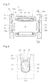
- the oil guide holes 26 are formed in the wall surfaces of the tapered groove sections 25a, but as shown in Figs. 5 and 6 , the oil guide holes 26 may be formed in the respective side plates 22 so as to lie on the extensions of the contact portions between the roller elements 43 in the loaded regions T of the respective bearings, where radial loads are applied, and the roller element rolling surfaces 32 on the outer peripheries of the roller shafts 31. With this arrangement, oil flowing into the oil guide holes 26 more smoothly flows into the roller element bearings 41, so that oil can be effectively introduced into the roller element bearings 41.
- Figs. 7 and 8 show different shaft engaging portions 25.
- those shown in Figs. 7 and 8 each comprise a tapered groove section 25a and a shaft support section 25b which is connected to the narrow end of the tapered groove section 25a.
- the shaft support section 25b is formed with opposed flat surfaces 27 on the inner wall thereof which is brought into surface contact with flat surfaces 33 formed on the outer periphery of the corresponding end of the roller shaft 31, thereby preventing rotation of the roller shaft 31.
- the tapered groove section 25a has side surfaces connected to the ends of the respective flat surfaces 27 so as to be moderately inclined outwardly from the ends of the flat surfaces 27.
- roller shafts 31 When the roller shafts 31 are inserted into the shaft engaging portions 25 of Figs. 7 and 8 , the end surfaces of the roller shafts 31 press the guide surfaces 29 of the respective anti-separation protrusions 28, thereby smoothly elastically deforming the anti-separation protrusions 28 so as to permit passage of the ends of the shafts through the respective anti-separation protrusions 28.
- the anti-separation protrusions 28 elastically return to their original shape, thus engaging the outer peripheries of the roller shafts 31 at their ends.
- the roller shafts 31 can thus be smoothly mounted in position.
- the side plates 22 may be formed by molding with the roller shafts 31 inserted in the respective roller element bearings such that the ends of the roller shafts 31 are embedded in the side plates 22.
- Figs. 9 and 10 show still different shaft engaging portions 25.
- These shaft engaging portions 25 are in the form of shaft holes extending through the side plates 22 from one to the other side thereof, each shaft hole having an oil guide hole 26 comprising an axial groove formed in the inner periphery of the shaft hole.
- the shaft engaging portions 25 are in the form of shaft holes extending through the side plates from one to the other side thereof
- the guide base 21 when the guide base 21 is formed by molding a resin in molds, the flow of molten resin is divided into two at a position upstream of each shaft hole 25, and the thus divided flows of molten resin meet at a position downstream of the shaft hole 25.
- the divided flows meet, they are not mixed together and thus form a weld line. Since the guide base 21 is low in strength at such weld lines, if the weld lines form in loaded regions, the guide base 21 tends to be damaged and thus its durability decreases.
- the loaded regions of the guide base 21 refer to the portions of the guide base 21 where high loads are applied from the timing chain 5 through the rollers 41 and the roller shafts 31.
- the loaded regions of the guide base 21 are indicated by the two-dot chain lines T in Fig. 10 .
- the guide base 21 is formed such that each weld line L is located between the intersections "a" and "b" between the circular inner surface of each shaft hole 25 and the diametric line A that passes the center O of the circular inner surface of the shaft hole 25 and extends in the width direction of the side plate 22.
- the guide base 21 is formed such that the weld line L is located on the horizontal line that passes the center O of the shaft hole 25 (namely, the line perpendicular to the line A) so that the weld line L is located farthest from the loaded regions T in the region between the intersections "a" and "b".
- the ratio of L 2 to L 1 may be determined at 1 to 3 or less too.
Landscapes
- Engineering & Computer Science (AREA)
- General Engineering & Computer Science (AREA)
- Mechanical Engineering (AREA)
- Devices For Conveying Motion By Means Of Endless Flexible Members (AREA)
- General Details Of Gearings (AREA)
Applications Claiming Priority (3)
| Application Number | Priority Date | Filing Date | Title |
|---|---|---|---|
| JP2012118389A JP5992724B2 (ja) | 2012-05-24 | 2012-05-24 | チェーンガイドおよびチェーン伝動装置 |
| JP2012186235A JP2014043887A (ja) | 2012-08-27 | 2012-08-27 | チェーンガイドおよびチェーン伝動装置 |
| PCT/JP2013/064467 WO2013176248A1 (ja) | 2012-05-24 | 2013-05-24 | チェーンガイドおよびチェーン伝動装置 |
Publications (3)
| Publication Number | Publication Date |
|---|---|
| EP2857718A1 true EP2857718A1 (de) | 2015-04-08 |
| EP2857718A4 EP2857718A4 (de) | 2015-06-10 |
| EP2857718B1 EP2857718B1 (de) | 2017-01-04 |
Family
ID=49623928
Family Applications (1)
| Application Number | Title | Priority Date | Filing Date |
|---|---|---|---|
| EP13793188.7A Not-in-force EP2857718B1 (de) | 2012-05-24 | 2013-05-24 | Kettenführung und kettenantriebsvorrichtung |
Country Status (4)
| Country | Link |
|---|---|
| US (1) | US9400046B2 (de) |
| EP (1) | EP2857718B1 (de) |
| CN (1) | CN104321559B (de) |
| WO (1) | WO2013176248A1 (de) |
Families Citing this family (4)
| Publication number | Priority date | Publication date | Assignee | Title |
|---|---|---|---|---|
| JP5980177B2 (ja) * | 2013-07-22 | 2016-08-31 | 株式会社椿本チエイン | チェーンガイド |
| JP6278673B2 (ja) * | 2013-11-28 | 2018-02-14 | Ntn株式会社 | チェーンガイドおよびチェーン伝動装置 |
| JP6265810B2 (ja) * | 2014-03-27 | 2018-01-24 | Ntn株式会社 | チェーンガイドおよびチェーン伝動装置 |
| USD1066147S1 (en) * | 2023-07-17 | 2025-03-11 | ZZ Performance, LLC | Timing chain guide |
Family Cites Families (80)
| Publication number | Priority date | Publication date | Assignee | Title |
|---|---|---|---|---|
| US68625A (en) * | 1867-09-10 | Improvement in belt-tightener | ||
| US993684A (en) * | 1909-11-11 | 1911-05-30 | Felten & Guilleaume Lahmeyerwe | Transporting mechanism. |
| US1338293A (en) * | 1918-03-23 | 1920-04-27 | Renault Louis | Driving-chain |
| US1579245A (en) * | 1919-11-13 | 1926-04-06 | Gordon R Pennington | Spring suspension for track-laying tractors |
| USRE15894E (en) * | 1921-03-30 | 1924-08-19 | Basfb j | |
| US1499920A (en) * | 1923-01-17 | 1924-07-01 | Norfolk Iron Company | Conveyer |
| US2349281A (en) * | 1942-02-07 | 1944-05-23 | George H Kendall | Pulley bearing |
| US2341273A (en) * | 1942-08-05 | 1944-02-08 | Boeing Aircraft Co | Cable tensioning device |
| US2709371A (en) * | 1951-10-01 | 1955-05-31 | Singer Mfg Co | Universal bobbin winder pulleys |
| US2729110A (en) * | 1953-05-07 | 1956-01-03 | Automatic Steel Products Inc | Sheet metal pulley construction for tooth grip belts |
| US2892206A (en) * | 1953-11-12 | 1959-06-30 | Trico Products Corp | Windshield wiper drive mechanism |
| US2827153A (en) * | 1954-04-07 | 1958-03-18 | Rapids Standard Co Inc | Powered roll conveyors |
| US2964155A (en) * | 1958-12-26 | 1960-12-13 | Leonard B Flowers | Conveyor |
| JPS4331780Y1 (de) * | 1964-11-16 | 1968-12-24 | ||
| US3598194A (en) * | 1968-06-10 | 1971-08-10 | Joachim Wappler | Final drive for terrain vehicle |
| US3586142A (en) * | 1969-05-01 | 1971-06-22 | Rapistan Inc | Rail for racks and the like |
| US3950046A (en) * | 1973-08-30 | 1976-04-13 | Industriewerk Schaeffler Ohg | Bearing plate |
| US3888217A (en) * | 1973-09-24 | 1975-06-10 | Charles A Hisserich | Camshaft belt drive for variable valve timing |
| US4078641A (en) * | 1974-04-04 | 1978-03-14 | F.E.I., Inc. | Sanitary roller conveyor |
| US3930323A (en) * | 1974-11-29 | 1976-01-06 | General Motors Corporation | Chain tensioning mechanism for scraper elevator device |
| US3951484A (en) * | 1975-04-14 | 1976-04-20 | Albert G. Nicholson | Roller assembly in a turn chain assembly |
| US4068535A (en) * | 1975-11-10 | 1978-01-17 | David L. Ray | Method and apparatus for controlling the tension of drive belts |
| US4208078A (en) * | 1977-08-29 | 1980-06-17 | Koyo Seiko Company Limited | Cylindrical roller bearings |
| US4213523A (en) * | 1978-09-11 | 1980-07-22 | C. L. Frost & Son, Inc. | Conveyor roller assembly |
| DE8025902U1 (de) * | 1980-09-27 | 1981-01-15 | Skf Kugellagerfabriken Gmbh, 8720 Schweinfurt | Rolle, insbesondere Spannrolle für Riementriebe o.dgl |
| US4474562A (en) * | 1980-12-03 | 1984-10-02 | Fag Kugelfischer Georg Schafer & Co. | Tensioner for motor-vehicle timing belt |
| US4416648A (en) * | 1981-01-12 | 1983-11-22 | Dyneer Corporation | Belt tensioner |
| US4416647A (en) * | 1981-05-26 | 1983-11-22 | Dayco Corporation | Belt tensioner |
| AU554589B2 (en) * | 1983-05-23 | 1986-08-28 | Fuji Kiko Co. Ltd. | Grooved pulley and manufacturing method therefor |
| JPH0247800Y2 (de) * | 1985-04-30 | 1990-12-14 | ||
| US4723516A (en) * | 1985-11-25 | 1988-02-09 | Slagley Michael W | Valve open duration and timing controller |
| CS265980B1 (en) * | 1987-09-02 | 1989-11-14 | Burysek Frantisek | Device for belt pressure with spindleless spinning frame |
| JPH0623776Y2 (ja) * | 1987-11-27 | 1994-06-22 | 日本精工株式会社 | ころ軸受部用フローティングシール |
| JPH01150070A (ja) * | 1987-12-04 | 1989-06-13 | Mitsubishi Electric Corp | プーリおよびその製造方法 |
| US4969548A (en) * | 1988-04-27 | 1990-11-13 | Kornylak Corporation | Compression set limiting gravity conveyor |
| FR2640714B1 (fr) * | 1988-12-16 | 1991-02-08 | Caoutchouc Manuf Plastique | Dispositif de tension par transmission par lien souple a double galet sur bague elastique de torsion |
| US4892508A (en) * | 1989-06-13 | 1990-01-09 | Robert Ryan | Safety guide support for pivoting pulley |
| US5244439A (en) * | 1992-05-27 | 1993-09-14 | Rogus Thomas E | Roller chain idler replacement |
| US5368403A (en) * | 1993-04-30 | 1994-11-29 | Hewlett-Packard Company | Carriage support system for computer driven printer |
| US5441458A (en) * | 1994-01-14 | 1995-08-15 | Rogus; Thomas E. | Grooved roller chain idler |
| US5848846A (en) * | 1996-07-26 | 1998-12-15 | Ntn Corporation | Shell type needle roller bearing and method of producing the same |
| JP3805449B2 (ja) * | 1996-12-19 | 2006-08-02 | 株式会社椿本チエイン | ローラチェーン用走行案内シュー |
| JP3487540B2 (ja) * | 1997-07-01 | 2004-01-19 | 本田技研工業株式会社 | チェーン駆動車両のチェーンローラ構造 |
| JP3269011B2 (ja) * | 1997-07-28 | 2002-03-25 | 株式会社椿本チエイン | 伝動チェーンの走行案内シュー |
| JP3855383B2 (ja) * | 1997-08-07 | 2006-12-06 | 株式会社デンソー | プーリ一体型ロータの製造方法 |
| EP0931737A1 (de) * | 1998-01-22 | 1999-07-28 | Rexnord Marbett S.p.A. | Vorrichtung mit Leitrollen für eine Leitwand für Stückgutförderer |
| US5967925A (en) * | 1998-03-30 | 1999-10-19 | Ford Global Technologies, Inc. | Pulley with controlled surface irregularity for an internal combustion engine |
| JP2000130527A (ja) * | 1998-10-30 | 2000-05-12 | Nissan Motor Co Ltd | Vベルト式無段変速機用プーリー及び無段変速機 |
| US6346057B1 (en) * | 1998-11-25 | 2002-02-12 | Klaus Edelmann | Belt tensioning device |
| US6245436B1 (en) * | 1999-02-08 | 2001-06-12 | David Boyle | Surfacing of aluminum bodies by anodic spark deposition |
| US6155218A (en) * | 1999-03-22 | 2000-12-05 | The United States Of America As Represented By The Secretary Of The Army | Cam advancing and retarding mechanism |
| US6179740B1 (en) * | 1999-06-02 | 2001-01-30 | Moxee Innovations Corporation | Dual-adjustable belt idler |
| US20010053727A1 (en) * | 2000-06-13 | 2001-12-20 | Eijiro Nakashima | Belt transmission system |
| US7419447B2 (en) * | 2000-10-03 | 2008-09-02 | The Gates Corporation | Dual linear belt tensioner |
| DE10131916A1 (de) * | 2001-07-05 | 2003-01-23 | Muhr & Bender Kg | Spanneinrichtung für Zugmittel, insbesondere Riemenspanneinrichtung |
| DE60239630D1 (de) * | 2001-11-08 | 2011-05-12 | Jtekt Corp | Lagervorrichtung zur abstützung einer ritzelwelle |
| JP3336337B1 (ja) * | 2001-11-14 | 2002-10-21 | 株式会社椿本チエイン | 伝動装置用プラスチック製可動ガイド |
| US6866602B2 (en) * | 2002-07-01 | 2005-03-15 | Performance Engineering & Machine Inc. | Belt drive system |
| JP3734781B2 (ja) | 2002-08-29 | 2006-01-11 | 伸一 真木 | 軸固定構造およびコンベヤ |
| JP4376503B2 (ja) * | 2002-10-25 | 2009-12-02 | ボルグワーナー・モールステック・ジャパン株式会社 | サイレントチェーン用スプロケットおよびその製造方法 |
| JP2005042879A (ja) * | 2003-07-25 | 2005-02-17 | Ntn Corp | 鋼板製軌道輪付きころ軸受 |
| EP1664561A4 (de) * | 2003-09-12 | 2007-01-10 | Minebea Co Ltd | Dynamische fluidlagereinheit |
| US7611289B2 (en) * | 2004-09-24 | 2009-11-03 | Ntn Corporation | Rollers with retainer |
| JP4360999B2 (ja) * | 2004-10-07 | 2009-11-11 | 株式会社椿本チエイン | 伝動チェーン |
| JP4851105B2 (ja) * | 2005-03-07 | 2012-01-11 | バンドー化学株式会社 | ベルト伝動装置 |
| CA2612834A1 (en) * | 2005-06-16 | 2006-12-28 | Moxee Innovations Corporation | Tensioning method |
| DE102006002224A1 (de) * | 2006-01-16 | 2007-07-19 | Schaeffler Kg | Anordnung zum Schutz eines Substrates vor Korrosion, Verfahren zu dessen Herstellung sowie Riemenscheibe |
| US7815533B2 (en) * | 2006-09-18 | 2010-10-19 | Ford Global Technologies | Camshaft drive system for internal combustion engine |
| FR2907526B1 (fr) * | 2006-10-20 | 2009-06-26 | Skf Ab | Dispositif de galet tendeur ou enrouleur. |
| DE102007061020A1 (de) * | 2007-12-18 | 2009-06-25 | Schaeffler Kg | Wälzlager für eine Spann- oder Umlenkrolle in einem Riementrieb |
| JP4667478B2 (ja) | 2008-02-26 | 2011-04-13 | 日立建機株式会社 | 走行装置 |
| US7866292B2 (en) * | 2008-03-26 | 2011-01-11 | AES Industries Inc | Apparatus and methods for continuous variable valve timing |
| ATE520899T1 (de) * | 2008-10-08 | 2011-09-15 | Ntn Toyo Bearing Co Ltd | Kettenspanner |
| DE102009004562B4 (de) * | 2009-01-14 | 2015-06-03 | Shw Casting Technologies Gmbh | Walzenkörper für eine Walze zur Behandlung eines Materials und Verfahren zur Herstellung eines Walzenkörpers |
| CN102301158A (zh) * | 2009-02-03 | 2011-12-28 | Ntn株式会社 | 链条导轨和紧链器装置 |
| JP5329346B2 (ja) * | 2009-08-27 | 2013-10-30 | Ntn株式会社 | チェーンガイドおよびチェーンテンショナ装置 |
| JP5702528B2 (ja) | 2009-09-09 | 2015-04-15 | Ntn株式会社 | チェーンガイドおよびチェーンテンショナ装置 |
| CN102400736A (zh) * | 2010-09-15 | 2012-04-04 | 重庆长安汽车股份有限公司 | 一种发动机正时链条系统的润滑结构 |
| CN103384784B (zh) * | 2011-02-23 | 2016-11-16 | Ntn株式会社 | 链条引导件和链条张紧装置 |
| JP2012172810A (ja) * | 2011-02-23 | 2012-09-10 | Ntn Corp | チェーンガイド及びチェーンテンショナ装置 |
-
2013
- 2013-05-24 CN CN201380026382.9A patent/CN104321559B/zh not_active Expired - Fee Related
- 2013-05-24 US US14/402,340 patent/US9400046B2/en not_active Expired - Fee Related
- 2013-05-24 WO PCT/JP2013/064467 patent/WO2013176248A1/ja not_active Ceased
- 2013-05-24 EP EP13793188.7A patent/EP2857718B1/de not_active Not-in-force
Also Published As
| Publication number | Publication date |
|---|---|
| US9400046B2 (en) | 2016-07-26 |
| CN104321559A (zh) | 2015-01-28 |
| EP2857718B1 (de) | 2017-01-04 |
| WO2013176248A1 (ja) | 2013-11-28 |
| EP2857718A4 (de) | 2015-06-10 |
| CN104321559B (zh) | 2017-08-25 |
| US20150105197A1 (en) | 2015-04-16 |
Similar Documents
| Publication | Publication Date | Title |
|---|---|---|
| EP2857718B1 (de) | Kettenführung und kettenantriebsvorrichtung | |
| US9464699B2 (en) | Chain guide and chain transmission device | |
| EP2738423B1 (de) | Kettenantriebsvorrichtung für nockenwellenantrieb | |
| EP2803880B1 (de) | Kettenführung und kettenantriebsvorrichtung | |
| EP3109511A1 (de) | Kettentriebvorrichtung zur ansteuerung von nockenwellen | |
| EP2738422B1 (de) | Kettenführung und kettenantriebsvorrichtung | |
| EP2735769A1 (de) | Kettenführung und kettenantrieb | |
| JP5992724B2 (ja) | チェーンガイドおよびチェーン伝動装置 | |
| JP6034567B2 (ja) | チェーンガイドおよびチェーン伝動装置 | |
| JP5933349B2 (ja) | チェーンガイドおよびチェーン伝動装置 | |
| EP3076047A1 (de) | Kettenführung und kettenantriebsvorrichtung | |
| JP2014020438A (ja) | チェーンガイドおよびチェーン伝動装置 | |
| JP5706260B2 (ja) | チェーンガイドおよびチェーン伝動装置 | |
| JP2014043887A (ja) | チェーンガイドおよびチェーン伝動装置 | |
| JP5706259B2 (ja) | チェーンガイドおよびチェーン伝動装置 | |
| JP2015068372A (ja) | チェーンガイドおよびチェーン伝動装置 | |
| JP2013024297A (ja) | チェーンガイドおよびチェーン伝動装置 | |
| JP2014001821A (ja) | チェーンガイドおよびチェーン伝動装置 | |
| JP2018040418A (ja) | チェーンガイドおよびチェーン伝動装置 |
Legal Events
| Date | Code | Title | Description |
|---|---|---|---|
| PUAI | Public reference made under article 153(3) epc to a published international application that has entered the european phase |
Free format text: ORIGINAL CODE: 0009012 |
|
| 17P | Request for examination filed |
Effective date: 20141222 |
|
| AK | Designated contracting states |
Kind code of ref document: A1 Designated state(s): AL AT BE BG CH CY CZ DE DK EE ES FI FR GB GR HR HU IE IS IT LI LT LU LV MC MK MT NL NO PL PT RO RS SE SI SK SM TR |
|
| AX | Request for extension of the european patent |
Extension state: BA ME |
|
| RA4 | Supplementary search report drawn up and despatched (corrected) |
Effective date: 20150512 |
|
| RIC1 | Information provided on ipc code assigned before grant |
Ipc: F16H 57/04 20100101ALI20150506BHEP Ipc: F16H 7/08 20060101AFI20150506BHEP Ipc: F16C 19/26 20060101ALI20150506BHEP Ipc: F16C 33/66 20060101ALI20150506BHEP Ipc: F16H 7/18 20060101ALI20150506BHEP |
|
| DAX | Request for extension of the european patent (deleted) | ||
| GRAP | Despatch of communication of intention to grant a patent |
Free format text: ORIGINAL CODE: EPIDOSNIGR1 |
|
| INTG | Intention to grant announced |
Effective date: 20160816 |
|
| GRAS | Grant fee paid |
Free format text: ORIGINAL CODE: EPIDOSNIGR3 |
|
| GRAA | (expected) grant |
Free format text: ORIGINAL CODE: 0009210 |
|
| AK | Designated contracting states |
Kind code of ref document: B1 Designated state(s): AL AT BE BG CH CY CZ DE DK EE ES FI FR GB GR HR HU IE IS IT LI LT LU LV MC MK MT NL NO PL PT RO RS SE SI SK SM TR |
|
| REG | Reference to a national code |
Ref country code: GB Ref legal event code: FG4D |
|
| REG | Reference to a national code |
Ref country code: CH Ref legal event code: EP |
|
| REG | Reference to a national code |
Ref country code: AT Ref legal event code: REF Ref document number: 859568 Country of ref document: AT Kind code of ref document: T Effective date: 20170115 |
|
| REG | Reference to a national code |
Ref country code: IE Ref legal event code: FG4D |
|
| REG | Reference to a national code |
Ref country code: DE Ref legal event code: R096 Ref document number: 602013016267 Country of ref document: DE |
|
| REG | Reference to a national code |
Ref country code: FR Ref legal event code: PLFP Year of fee payment: 5 |
|
| REG | Reference to a national code |
Ref country code: LT Ref legal event code: MG4D Ref country code: NL Ref legal event code: MP Effective date: 20170104 |
|
| REG | Reference to a national code |
Ref country code: AT Ref legal event code: MK05 Ref document number: 859568 Country of ref document: AT Kind code of ref document: T Effective date: 20170104 |
|
| PG25 | Lapsed in a contracting state [announced via postgrant information from national office to epo] |
Ref country code: NL Free format text: LAPSE BECAUSE OF FAILURE TO SUBMIT A TRANSLATION OF THE DESCRIPTION OR TO PAY THE FEE WITHIN THE PRESCRIBED TIME-LIMIT Effective date: 20170104 |
|
| PG25 | Lapsed in a contracting state [announced via postgrant information from national office to epo] |
Ref country code: NO Free format text: LAPSE BECAUSE OF FAILURE TO SUBMIT A TRANSLATION OF THE DESCRIPTION OR TO PAY THE FEE WITHIN THE PRESCRIBED TIME-LIMIT Effective date: 20170404 Ref country code: FI Free format text: LAPSE BECAUSE OF FAILURE TO SUBMIT A TRANSLATION OF THE DESCRIPTION OR TO PAY THE FEE WITHIN THE PRESCRIBED TIME-LIMIT Effective date: 20170104 Ref country code: GR Free format text: LAPSE BECAUSE OF FAILURE TO SUBMIT A TRANSLATION OF THE DESCRIPTION OR TO PAY THE FEE WITHIN THE PRESCRIBED TIME-LIMIT Effective date: 20170405 Ref country code: LT Free format text: LAPSE BECAUSE OF FAILURE TO SUBMIT A TRANSLATION OF THE DESCRIPTION OR TO PAY THE FEE WITHIN THE PRESCRIBED TIME-LIMIT Effective date: 20170104 Ref country code: IS Free format text: LAPSE BECAUSE OF FAILURE TO SUBMIT A TRANSLATION OF THE DESCRIPTION OR TO PAY THE FEE WITHIN THE PRESCRIBED TIME-LIMIT Effective date: 20170504 Ref country code: HR Free format text: LAPSE BECAUSE OF FAILURE TO SUBMIT A TRANSLATION OF THE DESCRIPTION OR TO PAY THE FEE WITHIN THE PRESCRIBED TIME-LIMIT Effective date: 20170104 |
|
| PG25 | Lapsed in a contracting state [announced via postgrant information from national office to epo] |
Ref country code: RS Free format text: LAPSE BECAUSE OF FAILURE TO SUBMIT A TRANSLATION OF THE DESCRIPTION OR TO PAY THE FEE WITHIN THE PRESCRIBED TIME-LIMIT Effective date: 20170104 Ref country code: BG Free format text: LAPSE BECAUSE OF FAILURE TO SUBMIT A TRANSLATION OF THE DESCRIPTION OR TO PAY THE FEE WITHIN THE PRESCRIBED TIME-LIMIT Effective date: 20170404 Ref country code: PT Free format text: LAPSE BECAUSE OF FAILURE TO SUBMIT A TRANSLATION OF THE DESCRIPTION OR TO PAY THE FEE WITHIN THE PRESCRIBED TIME-LIMIT Effective date: 20170504 Ref country code: LU Free format text: LAPSE BECAUSE OF NON-PAYMENT OF DUE FEES Effective date: 20170531 Ref country code: AT Free format text: LAPSE BECAUSE OF FAILURE TO SUBMIT A TRANSLATION OF THE DESCRIPTION OR TO PAY THE FEE WITHIN THE PRESCRIBED TIME-LIMIT Effective date: 20170104 Ref country code: SE Free format text: LAPSE BECAUSE OF FAILURE TO SUBMIT A TRANSLATION OF THE DESCRIPTION OR TO PAY THE FEE WITHIN THE PRESCRIBED TIME-LIMIT Effective date: 20170104 Ref country code: PL Free format text: LAPSE BECAUSE OF FAILURE TO SUBMIT A TRANSLATION OF THE DESCRIPTION OR TO PAY THE FEE WITHIN THE PRESCRIBED TIME-LIMIT Effective date: 20170104 Ref country code: ES Free format text: LAPSE BECAUSE OF FAILURE TO SUBMIT A TRANSLATION OF THE DESCRIPTION OR TO PAY THE FEE WITHIN THE PRESCRIBED TIME-LIMIT Effective date: 20170104 Ref country code: LV Free format text: LAPSE BECAUSE OF FAILURE TO SUBMIT A TRANSLATION OF THE DESCRIPTION OR TO PAY THE FEE WITHIN THE PRESCRIBED TIME-LIMIT Effective date: 20170104 |
|
| REG | Reference to a national code |
Ref country code: DE Ref legal event code: R097 Ref document number: 602013016267 Country of ref document: DE |
|
| PG25 | Lapsed in a contracting state [announced via postgrant information from national office to epo] |
Ref country code: RO Free format text: LAPSE BECAUSE OF FAILURE TO SUBMIT A TRANSLATION OF THE DESCRIPTION OR TO PAY THE FEE WITHIN THE PRESCRIBED TIME-LIMIT Effective date: 20170104 Ref country code: EE Free format text: LAPSE BECAUSE OF FAILURE TO SUBMIT A TRANSLATION OF THE DESCRIPTION OR TO PAY THE FEE WITHIN THE PRESCRIBED TIME-LIMIT Effective date: 20170104 Ref country code: CZ Free format text: LAPSE BECAUSE OF FAILURE TO SUBMIT A TRANSLATION OF THE DESCRIPTION OR TO PAY THE FEE WITHIN THE PRESCRIBED TIME-LIMIT Effective date: 20170104 Ref country code: SK Free format text: LAPSE BECAUSE OF FAILURE TO SUBMIT A TRANSLATION OF THE DESCRIPTION OR TO PAY THE FEE WITHIN THE PRESCRIBED TIME-LIMIT Effective date: 20170104 Ref country code: IT Free format text: LAPSE BECAUSE OF FAILURE TO SUBMIT A TRANSLATION OF THE DESCRIPTION OR TO PAY THE FEE WITHIN THE PRESCRIBED TIME-LIMIT Effective date: 20170104 |
|
| PLBE | No opposition filed within time limit |
Free format text: ORIGINAL CODE: 0009261 |
|
| STAA | Information on the status of an ep patent application or granted ep patent |
Free format text: STATUS: NO OPPOSITION FILED WITHIN TIME LIMIT |
|
| PG25 | Lapsed in a contracting state [announced via postgrant information from national office to epo] |
Ref country code: SM Free format text: LAPSE BECAUSE OF FAILURE TO SUBMIT A TRANSLATION OF THE DESCRIPTION OR TO PAY THE FEE WITHIN THE PRESCRIBED TIME-LIMIT Effective date: 20170104 Ref country code: DK Free format text: LAPSE BECAUSE OF FAILURE TO SUBMIT A TRANSLATION OF THE DESCRIPTION OR TO PAY THE FEE WITHIN THE PRESCRIBED TIME-LIMIT Effective date: 20170104 |
|
| REG | Reference to a national code |
Ref country code: CH Ref legal event code: PL |
|
| GBPC | Gb: european patent ceased through non-payment of renewal fee |
Effective date: 20170524 |
|
| PG25 | Lapsed in a contracting state [announced via postgrant information from national office to epo] |
Ref country code: MC Free format text: LAPSE BECAUSE OF FAILURE TO SUBMIT A TRANSLATION OF THE DESCRIPTION OR TO PAY THE FEE WITHIN THE PRESCRIBED TIME-LIMIT Effective date: 20170104 |
|
| REG | Reference to a national code |
Ref country code: IE Ref legal event code: MM4A |
|
| PG25 | Lapsed in a contracting state [announced via postgrant information from national office to epo] |
Ref country code: LI Free format text: LAPSE BECAUSE OF NON-PAYMENT OF DUE FEES Effective date: 20170531 Ref country code: CH Free format text: LAPSE BECAUSE OF NON-PAYMENT OF DUE FEES Effective date: 20170531 Ref country code: SI Free format text: LAPSE BECAUSE OF FAILURE TO SUBMIT A TRANSLATION OF THE DESCRIPTION OR TO PAY THE FEE WITHIN THE PRESCRIBED TIME-LIMIT Effective date: 20170104 |
|
| PG25 | Lapsed in a contracting state [announced via postgrant information from national office to epo] |
Ref country code: LU Free format text: LAPSE BECAUSE OF NON-PAYMENT OF DUE FEES Effective date: 20170524 |
|
| REG | Reference to a national code |
Ref country code: FR Ref legal event code: PLFP Year of fee payment: 6 |
|
| REG | Reference to a national code |
Ref country code: BE Ref legal event code: MM Effective date: 20170531 |
|
| PG25 | Lapsed in a contracting state [announced via postgrant information from national office to epo] |
Ref country code: GB Free format text: LAPSE BECAUSE OF NON-PAYMENT OF DUE FEES Effective date: 20170524 Ref country code: IE Free format text: LAPSE BECAUSE OF NON-PAYMENT OF DUE FEES Effective date: 20170524 |
|
| PG25 | Lapsed in a contracting state [announced via postgrant information from national office to epo] |
Ref country code: BE Free format text: LAPSE BECAUSE OF NON-PAYMENT OF DUE FEES Effective date: 20170531 |
|
| PG25 | Lapsed in a contracting state [announced via postgrant information from national office to epo] |
Ref country code: MT Free format text: LAPSE BECAUSE OF NON-PAYMENT OF DUE FEES Effective date: 20170524 |
|
| PG25 | Lapsed in a contracting state [announced via postgrant information from national office to epo] |
Ref country code: HU Free format text: LAPSE BECAUSE OF FAILURE TO SUBMIT A TRANSLATION OF THE DESCRIPTION OR TO PAY THE FEE WITHIN THE PRESCRIBED TIME-LIMIT; INVALID AB INITIO Effective date: 20130524 |
|
| PG25 | Lapsed in a contracting state [announced via postgrant information from national office to epo] |
Ref country code: CY Free format text: LAPSE BECAUSE OF FAILURE TO SUBMIT A TRANSLATION OF THE DESCRIPTION OR TO PAY THE FEE WITHIN THE PRESCRIBED TIME-LIMIT Effective date: 20170104 |
|
| PG25 | Lapsed in a contracting state [announced via postgrant information from national office to epo] |
Ref country code: MK Free format text: LAPSE BECAUSE OF FAILURE TO SUBMIT A TRANSLATION OF THE DESCRIPTION OR TO PAY THE FEE WITHIN THE PRESCRIBED TIME-LIMIT Effective date: 20170104 |
|
| PG25 | Lapsed in a contracting state [announced via postgrant information from national office to epo] |
Ref country code: TR Free format text: LAPSE BECAUSE OF FAILURE TO SUBMIT A TRANSLATION OF THE DESCRIPTION OR TO PAY THE FEE WITHIN THE PRESCRIBED TIME-LIMIT Effective date: 20170104 |
|
| PG25 | Lapsed in a contracting state [announced via postgrant information from national office to epo] |
Ref country code: AL Free format text: LAPSE BECAUSE OF FAILURE TO SUBMIT A TRANSLATION OF THE DESCRIPTION OR TO PAY THE FEE WITHIN THE PRESCRIBED TIME-LIMIT Effective date: 20170104 |
|
| PGFP | Annual fee paid to national office [announced via postgrant information from national office to epo] |
Ref country code: DE Payment date: 20200512 Year of fee payment: 8 Ref country code: FR Payment date: 20200414 Year of fee payment: 8 |
|
| REG | Reference to a national code |
Ref country code: DE Ref legal event code: R119 Ref document number: 602013016267 Country of ref document: DE |
|
| PG25 | Lapsed in a contracting state [announced via postgrant information from national office to epo] |
Ref country code: DE Free format text: LAPSE BECAUSE OF NON-PAYMENT OF DUE FEES Effective date: 20211201 |
|
| PG25 | Lapsed in a contracting state [announced via postgrant information from national office to epo] |
Ref country code: FR Free format text: LAPSE BECAUSE OF NON-PAYMENT OF DUE FEES Effective date: 20210531 |