EP2856089B1 - Zuführeinheit, zuführmodul mit mehreren zuführeinheiten und verfahren zum entladen eines konstanten massenflusses eines oder mehrerer pulver in einen aufnahmebehälter - Google Patents
Zuführeinheit, zuführmodul mit mehreren zuführeinheiten und verfahren zum entladen eines konstanten massenflusses eines oder mehrerer pulver in einen aufnahmebehälter Download PDFInfo
- Publication number
- EP2856089B1 EP2856089B1 EP12729233.2A EP12729233A EP2856089B1 EP 2856089 B1 EP2856089 B1 EP 2856089B1 EP 12729233 A EP12729233 A EP 12729233A EP 2856089 B1 EP2856089 B1 EP 2856089B1
- Authority
- EP
- European Patent Office
- Prior art keywords
- feeder
- feeder unit
- storage hopper
- refilling
- unit
- Prior art date
- Legal status (The legal status is an assumption and is not a legal conclusion. Google has not performed a legal analysis and makes no representation as to the accuracy of the status listed.)
- Active
Links
- 239000000843 powder Substances 0.000 title claims description 48
- 238000000034 method Methods 0.000 title claims description 41
- 238000007599 discharging Methods 0.000 title claims description 6
- 238000003860 storage Methods 0.000 claims description 64
- 238000005303 weighing Methods 0.000 claims description 31
- 238000012545 processing Methods 0.000 claims description 8
- 238000004140 cleaning Methods 0.000 claims description 5
- 239000000825 pharmaceutical preparation Substances 0.000 claims description 4
- 229940127557 pharmaceutical product Drugs 0.000 claims description 4
- 239000000203 mixture Substances 0.000 claims description 3
- 239000011540 sensing material Substances 0.000 claims description 3
- 230000000087 stabilizing effect Effects 0.000 claims description 2
- 239000000463 material Substances 0.000 description 18
- 238000002156 mixing Methods 0.000 description 15
- 238000004519 manufacturing process Methods 0.000 description 10
- 238000010924 continuous production Methods 0.000 description 6
- 238000011161 development Methods 0.000 description 5
- 238000011068 loading method Methods 0.000 description 5
- 238000005259 measurement Methods 0.000 description 5
- 230000000694 effects Effects 0.000 description 4
- 239000008186 active pharmaceutical agent Substances 0.000 description 3
- 238000004458 analytical method Methods 0.000 description 3
- 125000004122 cyclic group Chemical group 0.000 description 3
- 238000013461 design Methods 0.000 description 3
- 239000004615 ingredient Substances 0.000 description 3
- 238000012544 monitoring process Methods 0.000 description 3
- 238000010923 batch production Methods 0.000 description 2
- 239000000872 buffer Substances 0.000 description 2
- 230000001276 controlling effect Effects 0.000 description 2
- 230000001419 dependent effect Effects 0.000 description 2
- 238000001035 drying Methods 0.000 description 2
- 239000008187 granular material Substances 0.000 description 2
- 239000000546 pharmaceutical excipient Substances 0.000 description 2
- 238000002360 preparation method Methods 0.000 description 2
- 238000011057 process analytical technology Methods 0.000 description 2
- 230000001681 protective effect Effects 0.000 description 2
- 238000004513 sizing Methods 0.000 description 2
- 238000011144 upstream manufacturing Methods 0.000 description 2
- 238000009825 accumulation Methods 0.000 description 1
- 238000003556 assay Methods 0.000 description 1
- 230000033228 biological regulation Effects 0.000 description 1
- 238000011109 contamination Methods 0.000 description 1
- 239000003814 drug Substances 0.000 description 1
- 229940079593 drug Drugs 0.000 description 1
- 239000000428 dust Substances 0.000 description 1
- 238000005516 engineering process Methods 0.000 description 1
- 238000011049 filling Methods 0.000 description 1
- 238000009434 installation Methods 0.000 description 1
- 238000002955 isolation Methods 0.000 description 1
- 239000012464 large buffer Substances 0.000 description 1
- 239000003562 lightweight material Substances 0.000 description 1
- 239000007788 liquid Substances 0.000 description 1
- 238000004886 process control Methods 0.000 description 1
- 238000010925 quality by design Methods 0.000 description 1
- 238000011084 recovery Methods 0.000 description 1
- 230000001105 regulatory effect Effects 0.000 description 1
- 230000029058 respiratory gaseous exchange Effects 0.000 description 1
- 238000005096 rolling process Methods 0.000 description 1
- 238000013341 scale-up Methods 0.000 description 1
- 238000007789 sealing Methods 0.000 description 1
- 230000006641 stabilisation Effects 0.000 description 1
- 238000011105 stabilization Methods 0.000 description 1
- 238000010977 unit operation Methods 0.000 description 1
Images


Classifications
-
- B—PERFORMING OPERATIONS; TRANSPORTING
- B65—CONVEYING; PACKING; STORING; HANDLING THIN OR FILAMENTARY MATERIAL
- B65B—MACHINES, APPARATUS OR DEVICES FOR, OR METHODS OF, PACKAGING ARTICLES OR MATERIALS; UNPACKING
- B65B1/00—Packaging fluent solid material, e.g. powders, granular or loose fibrous material, loose masses of small articles, in individual containers or receptacles, e.g. bags, sacks, boxes, cartons, cans, or jars
- B65B1/04—Methods of, or means for, filling the material into the containers or receptacles
-
- B—PERFORMING OPERATIONS; TRANSPORTING
- B29—WORKING OF PLASTICS; WORKING OF SUBSTANCES IN A PLASTIC STATE IN GENERAL
- B29B—PREPARATION OR PRETREATMENT OF THE MATERIAL TO BE SHAPED; MAKING GRANULES OR PREFORMS; RECOVERY OF PLASTICS OR OTHER CONSTITUENTS OF WASTE MATERIAL CONTAINING PLASTICS
- B29B7/00—Mixing; Kneading
- B29B7/74—Mixing; Kneading using other mixers or combinations of mixers, e.g. of dissimilar mixers ; Plant
- B29B7/78—Mixing; Kneading using other mixers or combinations of mixers, e.g. of dissimilar mixers ; Plant by gravity, e.g. falling particle mixers
-
- G—PHYSICS
- G01—MEASURING; TESTING
- G01G—WEIGHING
- G01G13/00—Weighing apparatus with automatic feed or discharge for weighing-out batches of material
-
- B—PERFORMING OPERATIONS; TRANSPORTING
- B01—PHYSICAL OR CHEMICAL PROCESSES OR APPARATUS IN GENERAL
- B01F—MIXING, e.g. DISSOLVING, EMULSIFYING OR DISPERSING
- B01F21/00—Dissolving
-
- B—PERFORMING OPERATIONS; TRANSPORTING
- B29—WORKING OF PLASTICS; WORKING OF SUBSTANCES IN A PLASTIC STATE IN GENERAL
- B29B—PREPARATION OR PRETREATMENT OF THE MATERIAL TO BE SHAPED; MAKING GRANULES OR PREFORMS; RECOVERY OF PLASTICS OR OTHER CONSTITUENTS OF WASTE MATERIAL CONTAINING PLASTICS
- B29B7/00—Mixing; Kneading
- B29B7/02—Mixing; Kneading non-continuous, with mechanical mixing or kneading devices, i.e. batch type
- B29B7/22—Component parts, details or accessories; Auxiliary operations
- B29B7/24—Component parts, details or accessories; Auxiliary operations for feeding
- B29B7/242—Component parts, details or accessories; Auxiliary operations for feeding in measured doses
- B29B7/244—Component parts, details or accessories; Auxiliary operations for feeding in measured doses of several materials
-
- B—PERFORMING OPERATIONS; TRANSPORTING
- B29—WORKING OF PLASTICS; WORKING OF SUBSTANCES IN A PLASTIC STATE IN GENERAL
- B29B—PREPARATION OR PRETREATMENT OF THE MATERIAL TO BE SHAPED; MAKING GRANULES OR PREFORMS; RECOVERY OF PLASTICS OR OTHER CONSTITUENTS OF WASTE MATERIAL CONTAINING PLASTICS
- B29B7/00—Mixing; Kneading
- B29B7/02—Mixing; Kneading non-continuous, with mechanical mixing or kneading devices, i.e. batch type
- B29B7/22—Component parts, details or accessories; Auxiliary operations
- B29B7/28—Component parts, details or accessories; Auxiliary operations for measuring, controlling or regulating, e.g. viscosity control
-
- B—PERFORMING OPERATIONS; TRANSPORTING
- B29—WORKING OF PLASTICS; WORKING OF SUBSTANCES IN A PLASTIC STATE IN GENERAL
- B29B—PREPARATION OR PRETREATMENT OF THE MATERIAL TO BE SHAPED; MAKING GRANULES OR PREFORMS; RECOVERY OF PLASTICS OR OTHER CONSTITUENTS OF WASTE MATERIAL CONTAINING PLASTICS
- B29B7/00—Mixing; Kneading
- B29B7/30—Mixing; Kneading continuous, with mechanical mixing or kneading devices
- B29B7/58—Component parts, details or accessories; Auxiliary operations
- B29B7/60—Component parts, details or accessories; Auxiliary operations for feeding, e.g. end guides for the incoming material
- B29B7/603—Component parts, details or accessories; Auxiliary operations for feeding, e.g. end guides for the incoming material in measured doses, e.g. proportioning of several materials
-
- B—PERFORMING OPERATIONS; TRANSPORTING
- B29—WORKING OF PLASTICS; WORKING OF SUBSTANCES IN A PLASTIC STATE IN GENERAL
- B29B—PREPARATION OR PRETREATMENT OF THE MATERIAL TO BE SHAPED; MAKING GRANULES OR PREFORMS; RECOVERY OF PLASTICS OR OTHER CONSTITUENTS OF WASTE MATERIAL CONTAINING PLASTICS
- B29B7/00—Mixing; Kneading
- B29B7/30—Mixing; Kneading continuous, with mechanical mixing or kneading devices
- B29B7/58—Component parts, details or accessories; Auxiliary operations
- B29B7/72—Measuring, controlling or regulating
-
- B—PERFORMING OPERATIONS; TRANSPORTING
- B65—CONVEYING; PACKING; STORING; HANDLING THIN OR FILAMENTARY MATERIAL
- B65B—MACHINES, APPARATUS OR DEVICES FOR, OR METHODS OF, PACKAGING ARTICLES OR MATERIALS; UNPACKING
- B65B1/00—Packaging fluent solid material, e.g. powders, granular or loose fibrous material, loose masses of small articles, in individual containers or receptacles, e.g. bags, sacks, boxes, cartons, cans, or jars
- B65B1/30—Devices or methods for controlling or determining the quantity or quality or the material fed or filled
- B65B1/32—Devices or methods for controlling or determining the quantity or quality or the material fed or filled by weighing
-
- G—PHYSICS
- G01—MEASURING; TESTING
- G01G—WEIGHING
- G01G11/00—Apparatus for weighing a continuous stream of material during flow; Conveyor belt weighers
- G01G11/08—Apparatus for weighing a continuous stream of material during flow; Conveyor belt weighers having means for controlling the rate of feed or discharge
-
- G—PHYSICS
- G01—MEASURING; TESTING
- G01G—WEIGHING
- G01G13/00—Weighing apparatus with automatic feed or discharge for weighing-out batches of material
- G01G13/003—Details; specially adapted accessories
- G01G13/006—Container supply or discharge mechanism
-
- G—PHYSICS
- G01—MEASURING; TESTING
- G01G—WEIGHING
- G01G17/00—Apparatus for or methods of weighing material of special form or property
-
- G—PHYSICS
- G01—MEASURING; TESTING
- G01G—WEIGHING
- G01G19/00—Weighing apparatus or methods adapted for special purposes not provided for in the preceding groups
- G01G19/387—Weighing apparatus or methods adapted for special purposes not provided for in the preceding groups for combinatorial weighing, i.e. selecting a combination of articles whose total weight or number is closest to a desired value
- G01G19/393—Weighing apparatus or methods adapted for special purposes not provided for in the preceding groups for combinatorial weighing, i.e. selecting a combination of articles whose total weight or number is closest to a desired value using two or more weighing units
-
- B—PERFORMING OPERATIONS; TRANSPORTING
- B30—PRESSES
- B30B—PRESSES IN GENERAL
- B30B11/00—Presses specially adapted for forming shaped articles from material in particulate or plastic state, e.g. briquetting presses, tabletting presses
- B30B11/02—Presses specially adapted for forming shaped articles from material in particulate or plastic state, e.g. briquetting presses, tabletting presses using a ram exerting pressure on the material in a moulding space
- B30B11/08—Presses specially adapted for forming shaped articles from material in particulate or plastic state, e.g. briquetting presses, tabletting presses using a ram exerting pressure on the material in a moulding space co-operating with moulds carried by a turntable
-
- B—PERFORMING OPERATIONS; TRANSPORTING
- B30—PRESSES
- B30B—PRESSES IN GENERAL
- B30B15/00—Details of, or accessories for, presses; Auxiliary measures in connection with pressing
- B30B15/30—Feeding material to presses
- B30B15/302—Feeding material in particulate or plastic state to moulding presses
Definitions
- the present invention relates to a feeder unit comprising a storage hopper, a weighing cell, a conveyer, and a discharge end, the storage hopper being adapted to be connected to a refilling system, and the discharge end to a receiving container, the feeder unit having a predefined dead weight and the storage hopper having a predefined volume to define a capacity of the storage hopper below 10 liters, a working space in kgh being defined by the arithmetic product of dead weight in kg of the feeder unit and the refilling interval in h.
- the invention furthermore relates to a feeder module comprising a plurality of feeder units, and a method for discharging a constant mass flow of one or more powders into a receiving container.
- Typical manufacturing processes hitherto employed within the pharmaceutical field are of a batch nature. Batch manufacturing processes have a number of advantages and provide satisfactory results within many areas. However, due the increasingly widespread application of regulated criteria for monitoring and controlling in particular pharmaceutical manufacturing processes, and to the general increase in the demands to quality by design, the level of quality of monitoring and control attainable by a batch process is often not sufficient, i.a. due to the fact that settings are fixed. Furthermore, a relatively large buffer volume is required, entailing undesired backmixing of the material stream. As a consequence, manufacturers' and customers' focus of interest has shifted to continuous processes, in which settings may be varied and are allowed to change within a design space.
- Some examples of continuous processes have been devised in the prior art, for instance in EP 0 275 834 A1 , in which two or more ingredients are fed into the process line at various feed or inlet points, and the ingredients are mixed, dried and subsequently compacted in a conventional tabletting machine.
- the process line includes a first mixing unit, a drying unit, a sizing unit and a second mixing unit.
- the output corresponds to the aggregated input of ingredients at the feed or inlet points, i.e. all of the material is fed to the manufacturing machine in a continuous flow and at a constant rate. Due to a variety of factors, this is not feasible in practice. First, it is under any circumstances almost impossible to adjust the output from the mixing and drying units to provide a just-in-time supply of material to the tabletting machine. Second, the continuous production of tablets of a desired high level of quality requires careful monitoring, controlling and adjustment of process parameters in order to avoid a large rejection number from the tabletting machine. This may lead to accumulation of material along the process line awaiting adjustment of certain process parameters. In turn, this inevitably necessitates the use of intermediate buffer vessels in order to store material upstream of the tablet press.
- WO 2010/128359 (GEA Pharma Systems), a contained module being able to operate by a fully continuous process for the production of tablets is devised.
- all units of the tabletting process may be contained, thus reducing the risk of operator exposure and facilitating operation of the tablet press, as all preparations of the material stream fed to the tablet press are carried out in a contained and controlled manner.
- the term "contained" is defined by its level of containment according to suitable measurements, and is defined as at least dust-tight.
- the mixing unit refers to a unit operation generally capable of mixing or otherwise processing one, two or more components into a desired form.
- the mixing unit may thus also be capable of modifying the physical form of dry component(s) processed in the mixing unit, e.g. a feed stream of powder(s) may be converted to a granulate comprising the component(s).
- the mixing unit may be a granulator for making a granulate from dry powders, such as a granulator to which a granulating liquid is added, or a roller compactor. Further examples include a twin screw blender and a twin screw granulator.
- the mixing unit may include such equipment as a dryer, a dry blender, a continuous dry blender or the like.
- Dispensing or dosing the component(s) to the mixing unit, or to a receiving container upstream of the mixing unit most often takes place from storage hoppers connected to feeders which in turn supply the mixing unit or receiving container with the desired amount of powder(s) or other component(s).
- Feeding of powders is carried out by means of screw conveyors according to one of two main solutions: volumetric feeding or gravimetric feeding.
- volumetric feeding material held in a hopper is fed into a process at a constant volume per unit of time
- gravimetric feeding material is fed into a process at a constant weight per unit of time. The weight is measured by a weighing cell.
- Gravimetric feeders may operate on the loss-in-weight principle, which provides for more accurate dosing than feeders operating on other principles.
- EP 290 999 B1 One example of prior art concerned with achieving an increased accuracy when feeding powders is EP 290 999 B1 , in which powders are fed from storage hoppers to a weighing hopper and further to a mixing or preparation container.
- a feeder unit of the kind mentioned in the introduction which is furthermore characterized in that the dead weight of the feeder lies in the range 1 to 8 kg, and that the working space (ws) is below 0.2 kgh.
- the feeder unit is able to dispense a very accurately measured amount of material into a receiving container. Relative to feeder units having a higher dead weight and usually a lower refill interval, it is possible to obtain a higher accuracy in the measurement because of the lower dead weight of the feeder unit.
- Loss in-weight-feeders known in the art typically weigh up to 20-100 kg. Consequently, a higher inaccuracy is present because the loss in weight is so small, typically 0.05-0.1 g, and the weight of the feeder unit is included in weight measurement.
- the working space is below 0.1 kgh.
- the dead weight of the feeder unit lies in the range 1 to 6 kg, more preferably 1 to 3 kg.
- the storage hopper may have a predefined volume to define a capacity of the storage hopper below 5 liters, most preferably below 3 liters.
- the maximum net weight of powder in the storage hopper may lie in the interval 50 g to 5000 g the working space may be below 0.2 kgh, preferably below 0.1 kgh, most preferred below 0.05 kgh.
- the feeder unit may comprise a refilling valve connected to the storage hopper and a level or weight indicator above the refilling valve for controlled predosing of a refill amount.
- a controller adapted to store a conveying parameter together with a level or a weight may be provided.
- the weighing cell may be any weighing cell fulfilling the demands to accuracy on that point and preferably, the weighing cell is with Electro Magnetic Force Restoration (EMFR).
- EMFR Electro Magnetic Force Restoration
- each feeding unit In order to allow for detachment of parts of each feeding unit relative to other parts, it is advantageous that the storage hopper, the conveyer and the discharge end of each feeder unit are releasably connected to the weighing cell.
- the powder may in principle be transported or pumped from the storage hopper to the receiving container in any suitable manner.
- the conveyer is a twin screw conveyor.
- At least one, preferably both, of the screws of the twin screw conveyor has a variable pitch along its length underneath the storage hopper.
- At least one, preferably both, of the screws has a variable diameter along its length underneath the storage hopper.
- the variable diameter assures that the whole length of at least one screw, or of both screws, under the hopper is evenly loaded and hereby creating an even transport volume over the section of the hopper.
- the feeder unit comprises a controller for processing weight signals and compensate for external forces.
- the feeder unit may further comprise a sensor for sensing material variations.
- the storage hopper, the conveyer, and the discharge end of the feeder unit are contained and isolated from the weighing cell.
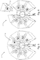
- a feeder module comprising a plurality of feeder units, wherein five to eight feeder units are arranged in a spokes-like configuration, each feeder unit extending radially outwards from an imaginary inner circle defined at the discharge end adapted to face the common receiving container to an imaginary outer circle defined by radially opposite end of each feeder unit, the feeder units being positioned substantially on radii extending from the imaginary inner circle.
- the feeder unit according to the invention may be utilised independently, it may thus form part of a feeder module which also benefits from the greater accuracy obtained.
- a method for discharging a constant mass flow of one or more powders into a receiving container comprising the steps of:
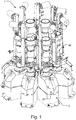
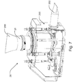
- a feeder module generally designated 1 is shown.
- the feeder module 1 comprises a plurality of feeder units 2.
- Each feeder unit 2 comprises a feeder part 20 and a weighing cell.
- a pre-feeder element 40 is attached to the feeder part 20.
- the feeder unit 2 according to the invention may also be used independently, as a single unit.
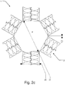
- the feeder module comprises five feeder units 2 and the diameter of the imaginary inner circle is 42-100 mm for a twin screw discharge tube (WDis) of 24 to 45 mm and a lateral clearance (CL) in between two twin screw discharge tubes of 1 to 10 mm, see Fig. 2d .
- WDis twin screw discharge tube
- CL lateral clearance
- the feeder module may comprise six feeder units and the diameter of the imaginary inner circle is 50-120 mm for a twin screw discharge tube of 24 to 45 mm and a lateral clearance (CL) in between two twin screw discharge tubes of 1 to 10 mm. See Fig. 2c .
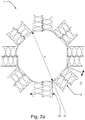
- the feeder module comprises seven feeder units and the diameter of the imaginary inner circle is 57-140 mm for a twin screw discharge tube of 24 to 45mm and a lateral clearance (CL) in between two twin screw discharge tubes of 1 to 10 mm, see Fig. 2b .
- the feeder module comprises eight feeder units and the diameter of the imaginary inner circle is 65-150 mm for a twin screw discharge tube of 24 to 45 mm and a lateral clearance in between two twin screw discharge tubes of 1 to 10 mm, see Fig. 2a .
- each feeder unit 2 includes a storage hopper 21 to contain material to be processed, a conveyer 22, a discharge end 23, and a weighing cell 24.
- the conveyer 22 has the function of transporting the material from the storage hopper 21 to discharge the material into a receiving container in a manner to be described in further detail below. Furthermore, it emerges from these Figures that the feeder units 2 are arranged in a single level to discharge into a common receiving container 3.
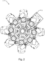
- the feeder units 2 are distributed substantially evenly over 360° in the same level, i.e. on substantially the same horizontal plane.
- the feeder units 2 are arranged in a spokes-like configuration, each feeder unit 2 extending radially outwards from an imaginary inner circle 31 defined at the discharge end 23 facing the common receiving container 3 to an imaginary outer circle defined by radially opposite end of each feeder unit.
- the feeder units 2 are positioned substantially on radii extending from the imaginary inner circle.
- the smallest possible dimension of the imaginary inner circle 31, and hence of the receiving container 3, depends on the number of feeder units 2 and of the physical dimensions of the individual feeder units 2. Typical values in embodiments comprising five feeder units, possibly distributed substantially evenly, are a diameter of the imaginary inner circle of 42-100 mm. In an embodiment comprising six feeder units, possibly distributed substantially evenly, the diameter of the imaginary inner circle is typically 50-120 mm. 7 feeders 57-140 mm. In the embodiment shown in Figs 1 to 4 , where eight feeder units 2 are adapted to be distributed substantially evenly, the diameter of the imaginary inner circle is typically 65 to 150 mm, in the specific embodiment approximately 107 mm. These values are dependent also on the desired clearance of 1-10 mm between parts of neighbouring feeder units and the dimensions of the individual parts. In the embodiment shown, the approximate width 26 of the discharge tube of each feeder unit 2 is 40 mm.
- the dimensioning of the feeder units 2 of the feeder module 1 depends on the field of application. Sizing may for instance be available as a range, such that each feeder unit 2 in a module 1 is of a different size.
- the dead weight of each feeder unit 2 is below 5 kg, and the capacity of the storage hopper of each feeder unit is less than 2 liters.
- the net weight of the powder to be filled into the storage hopper 21 of the individual feeder units 2 depends on the volume but also on the kind of powder applied.
- the maximum volume of powder in the storage hopper lies in the interval 1.6 to 2 liters.
- the maximum mass flow rate is approximately 50 kg/h.
- the ratio of powder weight and the maximum mass flow provide a maximum run time to empty a feeder or a maximum refilling interval pr. hour.
- the arithmetic product of the maximum refilling interval [h] and the dead weight [kg] of each feeder unit 2 is below 0.1 kgh. If the powder density is taken out of the equation and replaced by volume the maximum refilling interval is also the ratio of the hopper volume [L] and the feed rate [L/h]. E.g the capacity of the storage hopper of each feeder unit is less than 1.6 liters. The maximum flow rate is 100 L/h. The maximum refill interval is then 0.016h.
- the dead weight of each feeder unit 2 is typically 5 kg.
- the arithmetic product of the dead weight 5 kg and the maximum refill interval 0.016h is 0.08 kgh.
- the arithmetic product is typically below 0.2, preferably below 0.1, most preferably below 0.05 kgh.
- the storage hopper, the conveyer and the discharge end of each feeder unit are releasably connected to the weighing cell.
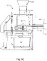
- Fig. 4 shows a detail cross section of the receiving hopper or receiving container 3.
- the discharge tube end 23 of the feeder units 2 with the imaginary circle 31 is smaller than the diameter of the receiving container 3.
- the discharged powder falls straight into the throat of the receiving container 3 and is substantially not hooking up to the inner walls of the receiving container 3.
- the configuration of the feeder units 2 of the feeder module is slightly different from that of Figs 1 to 4 .
- Detachment of one feeder unit 2, for instance for cleaning purposes, is carried out by detaching the feeder unit 2 from the receiving container 3. This may take place in a contained manner, for instance by other tightening or sealing devices, such as by Layflat tubing (LFT).
- LFT Layflat tubing
- a casing 250 is provided around the storage hopper, the conveyer 22 and the discharge end 23 of each feeder.
- the openings in the casing 250 are detached from the weighing cell.
- the receiving container, which is also detached from the weighing cell, and the feeder part 20 are isolated in a contained way by means of a lay flat tube 260.
- Lay flat tubes 260 are preferably made of a lightweight material having a very low stiffness, such that the weighing signal is left almost completely unaffected.
- a lay flat tube 260 may also be provided between the storage hopper 21 and a pre-feeder element (see Fig. 1 ).
- Refilling of the storage hoppers of the feeding units 2 may take place at different points in time, if expedient according to a predefined schedule.
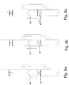
- the refilling takes place by means of a valve with air compensation, cf. part 25 shown in Figs 8a-c .
- Suitable valves are represented by plug valves, rotary dosing valves 41, butterfly valves 42 and slide valves 43.
- Above the valve a level sensor 44 is provided for use when the weight is fluctuating during refill of the feeder unit 2.
- the refilling takes place in a contained manner so as to at least assure that no dust enters the surrounding environment by the use of an appropriate seal or tube.
- the storage hopper 21 may be supplemented by a stirrer device 211 to break any bridges formed in the powder and to ensure that the conveyer 22 is fed properly.
- the conveyer 22 is in the embodiment shown a twin screw conveyor.
- the feeder unit 2 is additionally provided with lay flat tubing 260 and the receiving opening of the storage hopper 21 and at the discharge end 23.
- both of the concave screws 221 and 222 of the twin screw conveyor 22 have a variable pitch along its length, a first pitch p1 and a second pitch p2, being different from the first pitch P1.
- the conveyer 22 is driven by a motor M.
- the diameter of ach screw is constant.
- the pitch of each screw is constant, whereas the diameter of the screws is variable along the length shown as diameter d1 and diameter d2. It is also possible to have one or more screws with both a variable pitch and a variable diameter.
- the feeder module may comprise a number of additional features, such as analysis and control systems, loading and discharging stations etc.
- the feeder unit of the feeder module has a storage hopper of a limited volume, a rapid or high frequency refilling system is provided.
- feeders of a larger volume are refilled 4 to 8 times per hour.
- the powder which is dropping into the storage hopper causes disturbances on the weight signal (due to the impact forces of the powder) over a period which is equal to the sum of the powder drop time and scale stabilization time. Together with the time of rolling average filters this usually takes 30 s up to 60 s to get a stable weighing signal after a refill or top-up.
- the feeder is running in a volumetric mode.
- the screw speed is defined by the Feed Factor curve, the feed factor being defined as the equivalent of the weight per screw revolution, and the accuracy depending on how good the curve is fitting to the reality.
- Typical values of the refilling frequency of the feeder module according to the invention are one time per minute at a feed rate of 50 kg/h, i.e. mass flow 5 kg/h refill after 10 min. Due to its reduced weight and dynamic properties, the feeder module stabilizes in 2 to 4 seconds at a feed rate of 50 kg/h.
- the principle underlying the refilling system of the feeder module according to the invention is different from others as it is based on refilling each time the same amount of power under the same conditions.
- the refill system has either a weighing scale or a level sensor integrated combined with a volumetric dosing valve.
- the system itself acts as a (pre)feeder and stores the number of impeller turns together with a level or a weight.
- Such a refill or top-up system can also be used for material determination using the feeder data. Furthermore, it can be set to sense material variations. As the powder dosing valve always discharges in the center of the top-up tube, the shape of the powder stack is constant in the same area. During the powder drop, the powder at the bottom of the hopper is more compacted than the powder at the top of the hopper. However, the powder volume in the discharge tube is still not compacted. The screw speed remains unchanged until the fresh (i.e. more compacted) material is coming to the discharge opening. Each refill is reproducible and the system learns and converges to the optimal speed of the screws.
- feeder data may be used to calculate theoretical compositions and confirm BU and Assay over specified time periods.
- FFT fast Fourier Transform
- the feeder module is subjected to a number of external and internal disturbances.
- the disturbances normally include mechanical vibrations, wind load, bellow deformation forces etc. falling into one of two main types, viz. deterministic disturbances, which can be filtered, and nondeterministic disturbances, the effect of which must be reduced in other ways.
- AVC Active Vibration Compensation
- the feeder module according to the invention is dynamically more precise and faster responding compared to others. For instance, the recovery from non-cyclic external disturbances will only take about 2 to 4 seconds.
- a controller adapted to store a conveying parameter together with a level or a weight may be provided, and the feeder unit may further comprise a sensor for sensing material variations.
- the method is intended for discharging a constant mass flow of one or more powders into a receiving container. Primarily, the method forms part of a process for processing pharmaceutical products, but may also be applied in other fields.
- the method is suitable for being operated in a feeder unit 2 as described in the above and comprises the steps of:
- the storage hopper 21 is refilled 40 to 80 times per hour, preferably 50 to 70 times per hour.
- the stabilizing time after each refill is in the range 2 to 4 seconds.
- a working space is defined by the value resulting from the formula:
- the arithmetic product of the dead weight [kg] of each feeder unit and the refilling interval [h] is below 0.2 or even below 0.1. Due to the low powder mass in the hopper a very sensitive scale can be used which leads to a very high accuracy. The low powder mass makes a more frequent refilling necessary.
- the storage hoppers of the respective feeder units are refilled intermittently as described in the above.
- the method may include the further steps of detaching the storage hopper, the conveyer and the discharge end of each feeder unit from the weighing cell, and cleaning the storage hopper, the conveyer and the discharge end of each feeder unit in a contained manner.
Claims (25)
- Zuführeinheit (2), umfassend ein Vorratsbehältnis (21), eine Wägezelle (24), einen Förderer (22) und ein Austragsende (23), wobei das Vorratsbehältnis (21) ausgelegt ist, mit einem Nachfüllsystem verbunden zu sein, und das Austragsende (23) mit einem Aufnahmebehälter (3), wobei die Zuführeinheit (2) ein vordefiniertes Leergewicht (dw) aufweist und das Vorratsbehältnis (21) ein vordefiniertes Volumen aufweist, um eine Kapazität des Vorratsbehältnisses (21) unter 10 Litern zu definieren, wobei ein Arbeitsraum (ws) in kgh durch das arithmetische Produkt von Leergewicht (dw) in kg der Zuführeinheit (2) und dem Nachfüllintervall (ri) in h definiert ist, dadurch gekennzeichnet, dass das Leergewicht der Zuführeinheit (2) in dem Bereich 1 bis 8 kg liegt, und dass der Arbeitsraum (ws) unter 0,2 kgh liegt.
- Zuführeinheit (2) nach Anspruch 1, wobei der Arbeitsraum (ws) unter 0,1 kgh liegt.
- Zuführeinheit (2) nach Anspruch 1 oder 2, wobei das Leergewicht der Zuführeinheit (2) in dem Bereich 1 bis 6 kg, noch weiter bevorzugt 1 bis 3 kg, liegt.
- Zuführeinheit (2) nach einem der vorhergehenden Ansprüche, wobei das Vorratsbehältnis (21) ein vordefiniertes Volumen aufweist, um eine Kapazität des Vorratsbehältnisses (21) unter 5 Litern, am stärksten bevorzugt unter 3 Litern, zu definieren.
- Zuführeinheit (2) nach Anspruch 4, wobei das maximale Nettogewicht von Pulver in dem Vorratsbehältnis in dem Intervall 50 g bis 5000 g liegt und der Arbeitsraum unter 0,2 kgh, vorzugsweise unter 0,1 kgh, am stärksten bevorzugt unter 0,05 kgh, liegt.
- Zuführeinheit (2) nach einem der vorhergehenden Ansprüche, wobei die Zuführeinheit (2) ein Nachfüllventil (41, 42, 43) umfasst, das mit dem Vorratsbehältnis (21) und einer Füllstands- oder Gewichtsanzeige (44) über dem Nachfüllventil (41, 42, 43) für ein kontrolliertes Vordosieren einer Nachfüllmenge verbunden ist.
- Zuführeinheit (2) nach einem der vorhergehenden Ansprüche, wobei eine Steuerung, die ausgelegt ist, einen Förderparameter zusammen mit einem Füllstand oder einem Gewicht zu speichern, bereitgestellt ist.
- Zuführeinheit (2) nach einem der vorhergehenden Ansprüche, wobei die Wägezelle (24) eine Wägezelle mit einer elektromagnetischen Kraftkompensation (EMK) ist.
- Zuführeinheit (2) nach einem der vorhergehenden Ansprüche, wobei das Vorratsbehältnis (21), der Förderer (22) und das Austragsende (23) jeder Zuführeinheit (2) lösbar mit der Wägezelle (24) verbunden sind.
- Zuführeinheit (2) nach einem der vorhergehenden Ansprüche, wobei ein oder mehrere Förderer Doppelschneckenförderer (221, 222) sind.
- Zuführeinheit (2) nach Anspruch 10, wobei mindestens eine, vorzugsweise beide, der Schnecken des Doppelschneckenförderers eine variable Steigung (p1, p2) entlang ihrer Länge unterhalb des Vorratsbehältnisses (21) aufweist, oder mindestens eine, vorzugsweise beide, der Schnecken einen variablen Durchmesser (d2, d2) entlang ihrer Länge unterhalb des Vorratsbehältnisses (21) aufweist.
- Zuführeinheit (2) nach einem der vorhergehenden Ansprüche, wobei die Zuführeinheit (2) eine Steuerung für ein Verarbeiten von Gewichtssignalen und Kompensieren externer Kräfte umfasst.
- Zuführeinheit (2) nach einem der vorhergehenden Ansprüche, wobei die Zuführeinheit (2) ferner einen Sensor zum Erfassen von Materialschwankungen umfasst.
- Zuführeinheit (2) nach einem der vorhergehenden Ansprüche, wobei das Vorratsbehältnis (21), der Förderer (22) und das Austragsende (23) der Zuführeinheit (2) geschlossen und von der Wägezelle (24) isoliert sind.
- Zuführmodul (1) umfassend mehrere Zuführeinheiten (2) nach einem der Ansprüche 1 bis 14, wobei fünf bis acht Zuführeinheiten (2) in einer speichenartigen Anordnung angeordnet sind, wobei sich jede Zuführeinheit (2) radial nach außen von einem imaginären inneren Kreis (31), der an dem Austragsende (23) definiert ist, das ausgelegt ist, dem gemeinsamen Aufnahmebehälter (3) zugewandt zu sein, zu einem imaginären äußeren Kreis erstreckt, der durch radiale gegenüberliegende Enden jeder Zuführeinheit (2) definiert ist, wobei die Zuführeinheiten (2) im Wesentlichen an Radien positioniert sind, die sich von dem imaginären inneren Kreis (31) erstrecken.
- Zuführmodul nach Anspruch 15, wobei das Zuführmodul (1) 5 Zuführeinheiten (2) umfasst und der Durchmesser des imaginären inneren Kreises (31) 42-100 mm ist, oder wobei das Zuführmodul (1) sechs Zuführeinheiten (2) umfasst und der Durchmesser des imaginären inneren Kreises (31) 50-120 mm ist, oder wobei das Zuführmodul (1) acht Zuführeinheiten (2) umfasst und der Durchmesser (d) des imaginären inneren Kreises (31) 65-150 mm ist.
- Verfahren zum Austragen eines konstanten Massendurchflusses von einem oder mehreren Pulvern in einen Aufnahmebehälter, wobei das Verfahren in einer Zuführeinheit (2) nach Anspruch 1 bis 14 betrieben wird, wobei das Verfahren die folgenden Schritte umfasst:Bereitstellen einer Zuführeinheit (2) mit einem Vorratsbehältnis (21), einer Wägezelle (24), einem Förderer (22) und einem Austragsende (23),Verbinden des Vorratsbehältnisses (21) mit einem Nachfüllsystem mit einem Nachfüllventil (41, 42, 43),Verbinden des Nachfüllventils mit einer Füllstands- oder Gewichtsanzeige (44), wobei sich die Füllstands- oder Gewichtsanzeige (44) über dem Nachfüllventil (41, 42, 43) befindet,Verbinden des Austragsendes (23) mit einem Aufnahmebehälter (3),periodisches Nachfüllen des Vorratsbehältnisses (21) in vordefinierten Intervallen,Speichern von Daten während des Nachfüllens,wobei während des Nachfüllens das Nachfüllventil (41, 42, 43) die gleiche Menge an Pulver in das Vorratsbehältnis (21) abgibt, undder Förderer (22) gemäß den während vorheriger Nachfüllungen gesammelten Daten betrieben wird.
- Verfahren nach Anspruch 17, wobei ein Arbeitsraum (ws) in kgh durch das arithmetische Produkt des Leergewichts (dw) in kg der Zuführeinheit (2) und dem Nachfüllintervall (ri) in h definiert ist, und wobei der Arbeitsraum (ws) unter 0,2 kgh liegt.
- Verfahren nach Anspruch 18, wobei der Arbeitsraum (ws) unter 0,1 kgh liegt.
- Verfahren nach einem der Ansprüche 17 bis 19, wobei das Vorratsbehältnis (21) 40 bis 80 Mal pro Stunde, vorzugsweise 50 bis 70 Mal pro Stunde, nachgefüllt wird.
- Verfahren nach einem der Ansprüche 17 bis 20, wobei die Stabilisierungszeit nach jedem Nachfüllen in dem Bereich 2 bis 4 Sekunden liegt.
- Verfahren nach einem der Ansprüche 17 bis 21, wobei das Verfahren ferner die folgenden Schritte umfasst:Trennen des Vorratsbehältnisses (21), des Förderers (22) und des Austragsendes (23) jeder Zuführeinheit (2) von der Wägezelle (24) auf eine geschlossene Weise, undReinigen des Vorratsbehältnisses (21), des Förderers (22) und des Austragsendes (23) jeder Zuführeinheit (2).
- Verfahren nach einem der Ansprüche 17 bis 22, wobei der Aufnahmebehälter (3) mit einer Granuliervorrichtung verbunden ist, und ferner umfassend den folgenden Schritt
Granulieren der Mischung des einen oder der mehreren Pulver. - Verfahren nach einem der Ansprüche 17 bis 23, wobei der Aufnahmebehälter (3) mit einer Tablettenpresse verbunden ist, und ferner umfassend den folgenden Schritt
Tablettieren der Mischung des einen oder der mehreren Pulver. - Verfahren nach einem der Ansprüche 17 bis 24, wobei das Verfahren einen Teil eines Prozesses für ein Verarbeiten pharmazeutischer Produkte bildet.
Priority Applications (1)
| Application Number | Priority Date | Filing Date | Title |
|---|---|---|---|
| EP19150215.2A EP3489636A1 (de) | 2012-06-04 | 2012-06-04 | Zuführereinheit, zuführermodul mit einer vielzahl von zuführereinheiten und verfahren zum entladen eines konstanten massenflusses aus einem oder mehrerer pulver in einen aufnahmebehälter |
Applications Claiming Priority (1)
| Application Number | Priority Date | Filing Date | Title |
|---|---|---|---|
| PCT/IB2012/052803 WO2013182869A1 (en) | 2012-06-04 | 2012-06-04 | Feeder unit, a feeder module comprising a plurality of feeder units, and method for discharging a constant mass flow of one or more powders into a receiving container |
Related Child Applications (2)
| Application Number | Title | Priority Date | Filing Date |
|---|---|---|---|
| EP19150215.2A Division-Into EP3489636A1 (de) | 2012-06-04 | 2012-06-04 | Zuführereinheit, zuführermodul mit einer vielzahl von zuführereinheiten und verfahren zum entladen eines konstanten massenflusses aus einem oder mehrerer pulver in einen aufnahmebehälter |
| EP19150215.2A Division EP3489636A1 (de) | 2012-06-04 | 2012-06-04 | Zuführereinheit, zuführermodul mit einer vielzahl von zuführereinheiten und verfahren zum entladen eines konstanten massenflusses aus einem oder mehrerer pulver in einen aufnahmebehälter |
Publications (2)
| Publication Number | Publication Date |
|---|---|
| EP2856089A1 EP2856089A1 (de) | 2015-04-08 |
| EP2856089B1 true EP2856089B1 (de) | 2019-06-26 |
Family
ID=46331652
Family Applications (2)
| Application Number | Title | Priority Date | Filing Date |
|---|---|---|---|
| EP12729233.2A Active EP2856089B1 (de) | 2012-06-04 | 2012-06-04 | Zuführeinheit, zuführmodul mit mehreren zuführeinheiten und verfahren zum entladen eines konstanten massenflusses eines oder mehrerer pulver in einen aufnahmebehälter |
| EP19150215.2A Pending EP3489636A1 (de) | 2012-06-04 | 2012-06-04 | Zuführereinheit, zuführermodul mit einer vielzahl von zuführereinheiten und verfahren zum entladen eines konstanten massenflusses aus einem oder mehrerer pulver in einen aufnahmebehälter |
Family Applications After (1)
| Application Number | Title | Priority Date | Filing Date |
|---|---|---|---|
| EP19150215.2A Pending EP3489636A1 (de) | 2012-06-04 | 2012-06-04 | Zuführereinheit, zuführermodul mit einer vielzahl von zuführereinheiten und verfahren zum entladen eines konstanten massenflusses aus einem oder mehrerer pulver in einen aufnahmebehälter |
Country Status (6)
| Country | Link |
|---|---|
| US (3) | US20150183531A1 (de) |
| EP (2) | EP2856089B1 (de) |
| JP (1) | JP5926455B2 (de) |
| CN (3) | CN111220244A (de) |
| IN (1) | IN2014DN11260A (de) |
| WO (1) | WO2013182869A1 (de) |
Families Citing this family (18)
| Publication number | Priority date | Publication date | Assignee | Title |
|---|---|---|---|---|
| CN111220244A (zh) * | 2012-06-04 | 2020-06-02 | 基伊埃工程技术有限公司 | 加工药用粉末的方法及用于该方法的进料模块 |
| PL3094463T3 (pl) * | 2014-01-16 | 2021-12-13 | Ampacet Corporation | Układ ważenia i mieszania do wytwarzania mieszanki granulowanych składników oraz powiązany sposób |
| CN104635387B (zh) * | 2015-03-03 | 2017-10-10 | 合肥京东方光电科技有限公司 | 一种液晶滴注计量设备与方法 |
| CN104997637B (zh) * | 2015-05-07 | 2019-02-12 | 丹东金丸集团有限公司 | 水蜜丸填充装置 |
| DE102015108979A1 (de) | 2015-06-08 | 2016-12-08 | Windmöller & Hölscher Kg | Verfahren für die Durchführung eines Materialwechsels bei einer Extrusionsvorrichtung |
| DE202015105482U1 (de) * | 2015-10-16 | 2015-11-26 | INOEX GmbH Innovationen und Ausrüstungen für die Extrusionstechnik | Dosiervorrichtung zum Aufnehmen und Ausgeben von Schüttgut |
| JP7082455B2 (ja) | 2015-10-20 | 2022-06-08 | サクラ精機株式会社 | ワーク搬送装置 |
| CN105564671B (zh) * | 2015-12-01 | 2018-07-24 | 苏州信亨自动化科技有限公司 | 一种散装中药自动化定量分拣设备 |
| WO2018017561A1 (en) * | 2016-07-18 | 2018-01-25 | Cutispharma, Inc. | Apparatus and method for filling bulk materials into a container |
| CN108553306B (zh) * | 2018-04-24 | 2021-02-02 | 山东鲁北药业有限公司 | 蹄甲多肽片成型包装一体机 |
| KR102078678B1 (ko) * | 2018-05-11 | 2020-02-19 | 주식회사 아리제약 | 자동화된 정제형태의 의약품의 제조시스템 및 그 제조방법 |
| CN108792657A (zh) * | 2018-07-10 | 2018-11-13 | 苏州如德科技有限公司 | 中药饮片发药装置 |
| DE102018128043A1 (de) | 2018-11-09 | 2020-05-14 | Brabender Technologie Gmbh & Co. Kg | Vorrichtung zum Dosieren von Schüttgütern |
| CN109927968A (zh) * | 2019-03-12 | 2019-06-25 | 福建省亚热带植物研究所 | 一种胀气去除剂和农产品的包装方法 |
| CN110395490A (zh) * | 2019-07-24 | 2019-11-01 | 南京科亚化工成套装备有限公司 | 一种双螺杆防架桥喂料装置 |
| IT202000002281A1 (it) * | 2020-02-05 | 2020-05-05 | Hero Europe S R L | Dispositivo per erogare e dosare materiali in polvere o pastosi o liquidi |
| CN112123826B (zh) * | 2020-09-08 | 2022-05-24 | 浙江中天能橡胶股份有限公司 | 一种高性能输送带的制造方法 |
| CN113859602B (zh) * | 2021-09-28 | 2023-04-07 | 太原理工大学 | 锚网支护用锚固剂无人化生产装备 |
Family Cites Families (58)
| Publication number | Priority date | Publication date | Assignee | Title |
|---|---|---|---|---|
| CA961789A (en) * | 1972-11-24 | 1975-01-28 | Macmillan Bloedel Research Limited | Screw conveyor for particulate material |
| IT1117750B (it) * | 1977-08-05 | 1986-02-17 | Bersano Terenzio | Estrusore bivite/bistadio e pluristadio a doppia alimentazione |
| JPS60141394A (ja) | 1983-12-28 | 1985-07-26 | Mitsubishi Electric Corp | レ−ザ−加工機 |
| JPS6172828A (ja) | 1984-09-19 | 1986-04-14 | Kawasaki Heavy Ind Ltd | 予圧比可変型2サイクルエンジン |
| JPS61165558A (ja) * | 1985-04-16 | 1986-07-26 | 株式会社デンソー | 車両用冷房冷凍装置 |
| JPS6249734A (ja) | 1985-08-29 | 1987-03-04 | Nec Corp | 時分割多重分離方法及びその装置 |
| JPS6249734U (de) * | 1985-09-18 | 1987-03-27 | ||
| JPS62184434A (ja) | 1986-02-10 | 1987-08-12 | Hitachi Ltd | 光ビ−ム偏向器 |
| US5340211A (en) * | 1986-02-26 | 1994-08-23 | Micro Chemical, Inc. | Programmable apparatus and method for delivering microingredient feed additives by weight |
| US4815042A (en) * | 1986-02-26 | 1989-03-21 | Micro Chemical, Inc. | Programmable apparatus and method for delivering microingredient feed additives to animals by weight |
| JPH051788Y2 (de) * | 1986-05-15 | 1993-01-18 | ||
| JPH0621814B2 (ja) * | 1986-05-29 | 1994-03-23 | 大和製衡株式会社 | 計重装置の計重信号の濾波方法及び装置 |
| IE873172L (en) * | 1986-12-29 | 1988-06-29 | Harvard College | Continuous process for producing a comestible tablet |
| IT1210567B (it) * | 1987-04-22 | 1989-09-14 | Color Service Srl | Impianto di pesatura automatica per coloranti in polvere. |
| US4762252A (en) * | 1987-05-08 | 1988-08-09 | Hyer Industries, Inc. | Adaptation to major or sporadic disturbance error in weigh feeding apparatus |
| US4880142A (en) | 1987-05-12 | 1989-11-14 | Fuji Photo Film Co., Ltd. | Powder weighing mixer and method thereof |
| JP2587236B2 (ja) * | 1987-05-12 | 1997-03-05 | 富士写真フイルム株式会社 | 粉体計量方法 |
| DE3933471A1 (de) * | 1989-10-06 | 1991-04-18 | Schenck Ag Carl | Verfahren und vorrichtung zur verbesserung der dosiergenauigkeit einer geregelten differentialdosierwaage |
| DE4011314A1 (de) * | 1990-04-07 | 1991-10-10 | Hottinger Messtechnik Baldwin | Dehnungsmessstreifen und messgroessenaufnehmer mit derartigen dehnungsmessstreifen |
| GB2281113B (en) | 1990-09-12 | 1995-05-17 | British Gas Plc | Abandonment of a branch main |
| WO1992005410A1 (en) * | 1990-09-17 | 1992-04-02 | Anritsu Corporation | Measuring system for simply realizing high precision measuring of a wide range of work including viscous substances |
| US5143166A (en) * | 1991-02-01 | 1992-09-01 | Hough Richard M | Micro weighing system |
| DE4112268C1 (de) * | 1991-04-15 | 1992-03-12 | Plasma-Technik Ag, Wohlen, Ch | |
| US5148943A (en) * | 1991-06-17 | 1992-09-22 | Hydreclaim Corporation | Method and apparatus for metering and blending different material ingredients |
| DE4309109A1 (de) * | 1993-03-22 | 1994-09-29 | Schenck Ag Carl | Verfahren zur Störausblendung bei einer Differentialdosierwaage und Vorrichtung zur Durchführung des Verfahrens |
| DE4312281A1 (de) * | 1993-04-15 | 1994-10-20 | Eirich Maschf Gustav | Verfahren und Vorrichtung zur gravimetrischen Dosierung und Vermischung mindestens zweier Komponenten |
| US5423455A (en) * | 1993-06-25 | 1995-06-13 | Acrison, Inc. | Materials feeding system with level sensing probe and method for automatic bulk density determination |
| CH687869A5 (de) * | 1994-08-15 | 1997-03-14 | Buehler Ag Geb | Mikrodosiergeraet. |
| US5524796A (en) * | 1994-08-24 | 1996-06-11 | Hyer Industries, Inc. | Screw feeder with multiple concentric flights |
| US5738153A (en) * | 1995-11-03 | 1998-04-14 | E. I. Du Pont De Nemours And Company | Measuring and dispensing system for solid dry flowable materials |
| JP3476633B2 (ja) * | 1996-11-08 | 2003-12-10 | 愛三工業株式会社 | 粉体供給装置 |
| DE29714643U1 (de) * | 1997-08-16 | 1997-10-16 | Vollmar Hartmut | Verwiegeeinrichtung für ein eine oder mehrere Komponenten enthaltendes Aufgabegut |
| DE29714642U1 (de) * | 1997-08-16 | 1997-10-16 | Vollmar Hartmut | Zufuhrvorrichtung für ein rieselfähiges Aufgabegut in eine Dosiervorrichtung |
| US6168305B1 (en) * | 1998-02-27 | 2001-01-02 | Merrick Industries, Inc. | System for precisely controlling discharge rates for loss-in-weight feeder systems |
| FI107525B (fi) * | 1998-05-29 | 2001-08-31 | Raute Prec Oy | Menetelmä hienojakoisen aineen syöttämiseksi |
| US6056027A (en) * | 1998-10-20 | 2000-05-02 | Murray Equipment, Inc. | Dry material dispensing apparatus |
| US6284987B1 (en) * | 1999-07-29 | 2001-09-04 | Khalid F. Al-Modiny | Embedded weight scale |
| WO2001086238A1 (fr) * | 2000-05-11 | 2001-11-15 | Ishida Co., Ltd. | Dispositif transporteur et unite de test d'articles equipee de ce dernier |
| NL1015439C2 (nl) * | 2000-06-14 | 2001-12-17 | E H Klijn Beheer B V | Doseerinrichting. |
| GB2357588B (en) * | 2000-11-23 | 2002-01-09 | Bmh Chronos Richardson Ltd | Weighing apparatus |
| US20020084293A1 (en) * | 2001-01-02 | 2002-07-04 | Liad Weighing And Control Systems Ltd. | System for feeding portions of material to an injection molding machine |
| US6774318B2 (en) * | 2001-02-14 | 2004-08-10 | Process Control Corporation | Removable material hopper assembly and method of using same to eliminate residual ingredient material |
| ATE352413T1 (de) | 2001-09-05 | 2007-02-15 | Courtoy N V | Rundlauf-tablettierpresse und verfahren zum reinigen einer presse |
| US7311223B2 (en) * | 2004-05-07 | 2007-12-25 | Fluid Management, Inc. | Apparatus for dispensing a plurality of powders and method of compounding substances |
| CN1318826C (zh) * | 2005-01-28 | 2007-05-30 | 武汉科技大学 | 一种粉状物料的动态计量装置 |
| US8729410B2 (en) * | 2005-03-03 | 2014-05-20 | Cabinplant International A/S | Arrangement for conveying controlled portions of a product material to a combinational weighing system consisting of a transport screw with a quick release mechanism |
| US7301110B2 (en) * | 2005-03-03 | 2007-11-27 | Cabinplant International A/S | Arrangement for conveying controlled portions of a product material to a weighing system |
| CN2929669Y (zh) * | 2006-01-05 | 2007-08-01 | 向红跃 | 一种连续自动计量失重秤 |
| US7534970B2 (en) * | 2006-06-15 | 2009-05-19 | Schenck Accurate, Inc. | Counterbalanced dispensing system |
| CN201045587Y (zh) * | 2007-06-15 | 2008-04-09 | 武汉科恒工控工程有限责任公司 | 一种提高失重秤称量精度的装置 |
| US9057640B1 (en) * | 2008-12-16 | 2015-06-16 | Solomon Colors, Inc. | Bulk mortar system |
| DK2427166T3 (da) | 2009-05-07 | 2014-01-27 | Gea Pharma Systems Ltd | Tabletfremstillingsmodul og fremgangsmåde til kontinuerlig fremstilling af tabletter |
| CN101581597A (zh) * | 2009-06-29 | 2009-11-18 | 广东海川智能机器有限公司 | 一种组合称重装置及其操作方法 |
| CN202255578U (zh) * | 2011-08-12 | 2012-05-30 | 广东海川智能机器有限公司 | 组合秤 |
| CN111220244A (zh) * | 2012-06-04 | 2020-06-02 | 基伊埃工程技术有限公司 | 加工药用粉末的方法及用于该方法的进料模块 |
| WO2013182870A1 (en) * | 2012-06-04 | 2013-12-12 | Gea Process Engineering Nv | Feeder module and method for providing a mixture of one or more powders to a receiving container |
| US10138075B2 (en) * | 2016-10-06 | 2018-11-27 | Stephen B. Maguire | Tower configuration gravimetric blender |
| GB2538778B (en) * | 2015-05-28 | 2020-01-01 | Frito Lay Trading Co Gmbh | Multihead weigher and weighing method |
-
2012
- 2012-06-04 CN CN202010104630.9A patent/CN111220244A/zh active Pending
- 2012-06-04 JP JP2015515593A patent/JP5926455B2/ja active Active
- 2012-06-04 WO PCT/IB2012/052803 patent/WO2013182869A1/en active Application Filing
- 2012-06-04 CN CN201280073707.4A patent/CN104508436A/zh active Pending
- 2012-06-04 CN CN201710514712.9A patent/CN107356310B/zh active Active
- 2012-06-04 IN IN11260DEN2014 patent/IN2014DN11260A/en unknown
- 2012-06-04 US US14/404,972 patent/US20150183531A1/en not_active Abandoned
- 2012-06-04 EP EP12729233.2A patent/EP2856089B1/de active Active
- 2012-06-04 EP EP19150215.2A patent/EP3489636A1/de active Pending
-
2017
- 2017-07-03 US US15/640,654 patent/US10501213B2/en active Active
-
2019
- 2019-11-12 US US16/680,977 patent/US11479374B2/en active Active
Non-Patent Citations (18)
| Title |
|---|
| ANONYMOUS: "ATEX Konformitätsbewertung für elektrisches Betriebsmittel K-SFT III XPC3", K-TRON FEEDERS, 25 September 2009 (2009-09-25), pages 1, XP055765419 |
| ANONYMOUS: "Bau von Dosierern unter 5 kg", K-TRON, 24 March 2020 (2020-03-24), pages 1, XP055765471, [retrieved on 20210115] |
| ANONYMOUS: "Der Dosierer KT20 Orgasol von Hexcel, UK mit einer Waage SFT-II", K-TRON, 24 March 2020 (2020-03-24), pages 1 - 5, XP055765445 |
| ANONYMOUS: "Group K-TRON Product Information K4G Continuous Gravimetric Blender K4G-L-Group", K-TRON FEEDERS, 1 July 2011 (2011-07-01), pages 1 - 2, XP055765416, Retrieved from the Internet <URL:http://literature.puertoricosupplier.com/074/UR74008.pdf> [retrieved on 20210115] |
| ANONYMOUS: "K-ML-KT20 K-TRON Product Specification Twin Screw Loss-in-Weight Feeder", K-TRON, 1 March 2002 (2002-03-01), pages 1 - 2, XP055765439, Retrieved from the Internet <URL:http://www.pfe.pt/pfe/imdata/n18_117.pdf> [retrieved on 20210115] |
| ANONYMOUS: "K-MV-BSP-100 1 2 3 4 K-TRON Product Specification Volumetric Bulk Solids Pump (BSP) Feeder", K-TRON FEEDERS, 1 July 2011 (2011-07-01), pages 1 - 2, XP055765414, Retrieved from the Internet <URL:http://www.pfe.pt/pfe/imdata/n12_104.pdf> [retrieved on 20210115] |
| ANONYMOUS: "K-SFT-III K-TRON Product Specification Smart Force Transducer K-SFT-III Load Cell VibratingWirePrincipleofOperation K-SFT-III", K-TRON FEEDERS, 1 November 2009 (2009-11-01), pages 1 - 2, XP055765417, Retrieved from the Internet <URL:http://www.pfe.pt/pfe/imdata/n16_124.pdf> [retrieved on 20210115] |
| ANONYMOUS: "K-TRON Corporation", K-TRON, 1 June 1983 (1983-06-01), pages 1 - 18, XP055765465, [retrieved on 20210115] |
| ANONYMOUS: "K-TRON Product Specifi cation Loss-in-Weight Twin-Screw Microfeeder", K-TRON FEEDERS, 1 July 2007 (2007-07-01), pages 1 - 2, XP055765411, Retrieved from the Internet <URL:https://nanopdf.com/download/k-cl-sfs-mt12-k-ph-cl-sfs-mt12-k-tron-product_pdf> [retrieved on 20210115] |
| ANONYMOUS: "K-Tron Smart Force Transducer Weighing Technology for Gravimetric Feeding, Batching and Metering", K-TRON, 1 January 2004 (2004-01-01), pages 1 - 2, XP055765433 |
| ANONYMOUS: "Messung des Einschwingverhaltens der Coperion K- Tron SFT Wägezellen SFT II und SFT III", K-TRON FEEDERS, 24 March 2020 (2020-03-24), pages 1 - 14, XP055765423 |
| ANONYMOUS: "Product Specification Multi Weigh Gravi- metric Blender Multi Weigh W2, W3,W4", K-TRON, 1 April 2006 (2006-04-01), pages 1 - 2, XP055765456 |
| ANONYMOUS: "Product Specification Smart Force Transducer K-SFT II / Load Cell K-SFT II 12 - 20 kg", K-TRON, 1 May 2002 (2002-05-01), pages 1 - 2, XP055765443 |
| ANONYMOUS: "Smart Refill Technology in Loss-in-Weight Feeding", K-TRON, 1 November 2011 (2011-11-01), pages 1 - 5, XP055765455, Retrieved from the Internet <URL:https://www.mmsonline.com/cdn/cms/uploadedFiles/Ktron-Smart_Refill.pdf> [retrieved on 20210115] |
| DAVID H. WILSON: "How to troubleshoot and maintain your feeder", POWDER AND BULK ENGINEERING, 1 December 2001 (2001-12-01), XP055423681 |
| JUSTIN W. FERNANDEZ; PAUL W. CLEARY; WILLIAM MCBRIDE;: "Effect of screw design on hopper drawdown of spherical particles in a horizontal screw feeder", CHEMICAL ENGINEERING SCIENCE, OXFORD, GB, vol. 66, no. 22, 26 July 2011 (2011-07-26), GB, pages 5585 - 5601, XP028293154, ISSN: 0009-2509, DOI: 10.1016/j.ces.2011.07.043 |
| K-TRON CORPORATION: "K-Tron Model LW20 All-Digital Loss-in-Weight System", K-TRON SPECIFICATION, 1 September 1983 (1983-09-01), XP055423709 |
| K-TRON, PHOTO DER GEWICHTSMESSUNG EINER WÄGEZELLE SFT-III, October 2017 (2017-10-01) |
Also Published As
| Publication number | Publication date |
|---|---|
| WO2013182869A1 (en) | 2013-12-12 |
| US11479374B2 (en) | 2022-10-25 |
| CN107356310A (zh) | 2017-11-17 |
| US20150183531A1 (en) | 2015-07-02 |
| EP2856089A1 (de) | 2015-04-08 |
| JP5926455B2 (ja) | 2016-05-25 |
| IN2014DN11260A (de) | 2015-10-09 |
| JP2015528098A (ja) | 2015-09-24 |
| US20200079533A1 (en) | 2020-03-12 |
| CN111220244A (zh) | 2020-06-02 |
| US10501213B2 (en) | 2019-12-10 |
| CN107356310B (zh) | 2020-07-07 |
| CN104508436A (zh) | 2015-04-08 |
| US20170334583A1 (en) | 2017-11-23 |
| EP3489636A1 (de) | 2019-05-29 |
Similar Documents
| Publication | Publication Date | Title |
|---|---|---|
| US11479374B2 (en) | Feeder unit, feeder module comprising feeder units, and method for discharging a constant mass flow of one or more powders into a receiving container | |
| CN102389742B (zh) | 一种高精度配料设备及其控制方法 | |
| EP1279009B1 (de) | Drehende zellenrad-dosierwaage | |
| WO2013182870A1 (en) | Feeder module and method for providing a mixture of one or more powders to a receiving container | |
| US5125535A (en) | Gravimetric metering apparatus for bulk materials | |
| CN105612048A (zh) | 用于药片的连续生产的方法,用于执行此方法的压片系统,以及用于生产包含具有明显不同的颗粒尺寸的颗粒的至少两种成分的药片的压片系统的用途 | |
| JP2008183168A (ja) | 錠剤製造システム | |
| CN110711507B (zh) | 螺杆式多组份物料配料装置控制器 | |
| CN110697100A (zh) | 直落式多组份物料下料装置控制器 | |
| CN111302000A (zh) | 一种定量给料系统 | |
| CN201251474Y (zh) | 全自动称重装置 | |
| CN201873300U (zh) | 一种防爆型固相连续自动加料装置 | |
| CN105366382A (zh) | 一种将微量固体粉料和颗粒连续均匀计量配料装置 | |
| KR102069037B1 (ko) | 조립 시스템 | |
| JP2898403B2 (ja) | 微量配量装置 | |
| CN206013948U (zh) | 减重式微量添加机 | |
| JP2008517256A (ja) | バルク製品用重量計量装置 | |
| DK201270298A (en) | Feeder module and method for providing a mixture of on or more powders to a receing container | |
| CN206853619U (zh) | 小型通用叠加式自动配料机 | |
| JP2009019947A (ja) | 粉体計量装置 | |
| JP7173493B2 (ja) | 粉粒体定量供給装置 | |
| EP1518092A1 (de) | Loss-in-weight-zuführer mit entladungsdruckkompensator | |
| WO2006092030A2 (en) | System and method for adding a product to be dosed | |
| CN214398649U (zh) | 一种精确计量振动式喂料机 | |
| CN207632134U (zh) | 一种喂料称 |
Legal Events
| Date | Code | Title | Description |
|---|---|---|---|
| PUAI | Public reference made under article 153(3) epc to a published international application that has entered the european phase |
Free format text: ORIGINAL CODE: 0009012 |
|
| 17P | Request for examination filed |
Effective date: 20141202 |
|
| AK | Designated contracting states |
Kind code of ref document: A1 Designated state(s): AL AT BE BG CH CY CZ DE DK EE ES FI FR GB GR HR HU IE IS IT LI LT LU LV MC MK MT NL NO PL PT RO RS SE SI SK SM TR |
|
| AX | Request for extension of the european patent |
Extension state: BA ME |
|
| DAX | Request for extension of the european patent (deleted) | ||
| 17Q | First examination report despatched |
Effective date: 20160219 |
|
| TPAC | Observations filed by third parties |
Free format text: ORIGINAL CODE: EPIDOSNTIPA |
|
| GRAP | Despatch of communication of intention to grant a patent |
Free format text: ORIGINAL CODE: EPIDOSNIGR1 |
|
| STAA | Information on the status of an ep patent application or granted ep patent |
Free format text: STATUS: GRANT OF PATENT IS INTENDED |
|
| INTG | Intention to grant announced |
Effective date: 20180329 |
|
| GRAJ | Information related to disapproval of communication of intention to grant by the applicant or resumption of examination proceedings by the epo deleted |
Free format text: ORIGINAL CODE: EPIDOSDIGR1 |
|
| STAA | Information on the status of an ep patent application or granted ep patent |
Free format text: STATUS: EXAMINATION IS IN PROGRESS |
|
| GRAP | Despatch of communication of intention to grant a patent |
Free format text: ORIGINAL CODE: EPIDOSNIGR1 |
|
| STAA | Information on the status of an ep patent application or granted ep patent |
Free format text: STATUS: GRANT OF PATENT IS INTENDED |
|
| INTC | Intention to grant announced (deleted) | ||
| INTG | Intention to grant announced |
Effective date: 20180912 |
|
| GRAJ | Information related to disapproval of communication of intention to grant by the applicant or resumption of examination proceedings by the epo deleted |
Free format text: ORIGINAL CODE: EPIDOSDIGR1 |
|
| STAA | Information on the status of an ep patent application or granted ep patent |
Free format text: STATUS: EXAMINATION IS IN PROGRESS |
|
| GRAJ | Information related to disapproval of communication of intention to grant by the applicant or resumption of examination proceedings by the epo deleted |
Free format text: ORIGINAL CODE: EPIDOSDIGR1 |
|
| GRAL | Information related to payment of fee for publishing/printing deleted |
Free format text: ORIGINAL CODE: EPIDOSDIGR3 |
|
| GRAS | Grant fee paid |
Free format text: ORIGINAL CODE: EPIDOSNIGR3 |
|
| INTC | Intention to grant announced (deleted) | ||
| INTC | Intention to grant announced (deleted) | ||
| GRAJ | Information related to disapproval of communication of intention to grant by the applicant or resumption of examination proceedings by the epo deleted |
Free format text: ORIGINAL CODE: EPIDOSDIGR1 |
|
| GRAL | Information related to payment of fee for publishing/printing deleted |
Free format text: ORIGINAL CODE: EPIDOSDIGR3 |
|
| INTC | Intention to grant announced (deleted) | ||
| GRAR | Information related to intention to grant a patent recorded |
Free format text: ORIGINAL CODE: EPIDOSNIGR71 |
|
| STAA | Information on the status of an ep patent application or granted ep patent |
Free format text: STATUS: GRANT OF PATENT IS INTENDED |
|
| GRAA | (expected) grant |
Free format text: ORIGINAL CODE: 0009210 |
|
| STAA | Information on the status of an ep patent application or granted ep patent |
Free format text: STATUS: THE PATENT HAS BEEN GRANTED |
|
| INTG | Intention to grant announced |
Effective date: 20190508 |
|
| AK | Designated contracting states |
Kind code of ref document: B1 Designated state(s): AL AT BE BG CH CY CZ DE DK EE ES FI FR GB GR HR HU IE IS IT LI LT LU LV MC MK MT NL NO PL PT RO RS SE SI SK SM TR |
|
| REG | Reference to a national code |
Ref country code: GB Ref legal event code: FG4D |
|
| REG | Reference to a national code |
Ref country code: CH Ref legal event code: EP |
|
| REG | Reference to a national code |
Ref country code: AT Ref legal event code: REF Ref document number: 1148828 Country of ref document: AT Kind code of ref document: T Effective date: 20190715 |
|
| REG | Reference to a national code |
Ref country code: DE Ref legal event code: R096 Ref document number: 602012061404 Country of ref document: DE |
|
| REG | Reference to a national code |
Ref country code: IE Ref legal event code: FG4D |
|
| REG | Reference to a national code |
Ref country code: NL Ref legal event code: MP Effective date: 20190626 |
|
| PG25 | Lapsed in a contracting state [announced via postgrant information from national office to epo] |
Ref country code: HR Free format text: LAPSE BECAUSE OF FAILURE TO SUBMIT A TRANSLATION OF THE DESCRIPTION OR TO PAY THE FEE WITHIN THE PRESCRIBED TIME-LIMIT Effective date: 20190626 Ref country code: LT Free format text: LAPSE BECAUSE OF FAILURE TO SUBMIT A TRANSLATION OF THE DESCRIPTION OR TO PAY THE FEE WITHIN THE PRESCRIBED TIME-LIMIT Effective date: 20190626 Ref country code: AL Free format text: LAPSE BECAUSE OF FAILURE TO SUBMIT A TRANSLATION OF THE DESCRIPTION OR TO PAY THE FEE WITHIN THE PRESCRIBED TIME-LIMIT Effective date: 20190626 Ref country code: FI Free format text: LAPSE BECAUSE OF FAILURE TO SUBMIT A TRANSLATION OF THE DESCRIPTION OR TO PAY THE FEE WITHIN THE PRESCRIBED TIME-LIMIT Effective date: 20190626 Ref country code: NO Free format text: LAPSE BECAUSE OF FAILURE TO SUBMIT A TRANSLATION OF THE DESCRIPTION OR TO PAY THE FEE WITHIN THE PRESCRIBED TIME-LIMIT Effective date: 20190926 Ref country code: SE Free format text: LAPSE BECAUSE OF FAILURE TO SUBMIT A TRANSLATION OF THE DESCRIPTION OR TO PAY THE FEE WITHIN THE PRESCRIBED TIME-LIMIT Effective date: 20190626 |
|
| REG | Reference to a national code |
Ref country code: LT Ref legal event code: MG4D |
|
| PG25 | Lapsed in a contracting state [announced via postgrant information from national office to epo] |
Ref country code: GR Free format text: LAPSE BECAUSE OF FAILURE TO SUBMIT A TRANSLATION OF THE DESCRIPTION OR TO PAY THE FEE WITHIN THE PRESCRIBED TIME-LIMIT Effective date: 20190927 Ref country code: BG Free format text: LAPSE BECAUSE OF FAILURE TO SUBMIT A TRANSLATION OF THE DESCRIPTION OR TO PAY THE FEE WITHIN THE PRESCRIBED TIME-LIMIT Effective date: 20190926 Ref country code: LV Free format text: LAPSE BECAUSE OF FAILURE TO SUBMIT A TRANSLATION OF THE DESCRIPTION OR TO PAY THE FEE WITHIN THE PRESCRIBED TIME-LIMIT Effective date: 20190626 Ref country code: RS Free format text: LAPSE BECAUSE OF FAILURE TO SUBMIT A TRANSLATION OF THE DESCRIPTION OR TO PAY THE FEE WITHIN THE PRESCRIBED TIME-LIMIT Effective date: 20190626 |
|
| REG | Reference to a national code |
Ref country code: AT Ref legal event code: MK05 Ref document number: 1148828 Country of ref document: AT Kind code of ref document: T Effective date: 20190626 |
|
| PG25 | Lapsed in a contracting state [announced via postgrant information from national office to epo] |
Ref country code: EE Free format text: LAPSE BECAUSE OF FAILURE TO SUBMIT A TRANSLATION OF THE DESCRIPTION OR TO PAY THE FEE WITHIN THE PRESCRIBED TIME-LIMIT Effective date: 20190626 Ref country code: NL Free format text: LAPSE BECAUSE OF FAILURE TO SUBMIT A TRANSLATION OF THE DESCRIPTION OR TO PAY THE FEE WITHIN THE PRESCRIBED TIME-LIMIT Effective date: 20190626 Ref country code: PT Free format text: LAPSE BECAUSE OF FAILURE TO SUBMIT A TRANSLATION OF THE DESCRIPTION OR TO PAY THE FEE WITHIN THE PRESCRIBED TIME-LIMIT Effective date: 20191028 Ref country code: CZ Free format text: LAPSE BECAUSE OF FAILURE TO SUBMIT A TRANSLATION OF THE DESCRIPTION OR TO PAY THE FEE WITHIN THE PRESCRIBED TIME-LIMIT Effective date: 20190626 Ref country code: RO Free format text: LAPSE BECAUSE OF FAILURE TO SUBMIT A TRANSLATION OF THE DESCRIPTION OR TO PAY THE FEE WITHIN THE PRESCRIBED TIME-LIMIT Effective date: 20190626 Ref country code: SK Free format text: LAPSE BECAUSE OF FAILURE TO SUBMIT A TRANSLATION OF THE DESCRIPTION OR TO PAY THE FEE WITHIN THE PRESCRIBED TIME-LIMIT Effective date: 20190626 Ref country code: AT Free format text: LAPSE BECAUSE OF FAILURE TO SUBMIT A TRANSLATION OF THE DESCRIPTION OR TO PAY THE FEE WITHIN THE PRESCRIBED TIME-LIMIT Effective date: 20190626 |
|
| PG25 | Lapsed in a contracting state [announced via postgrant information from national office to epo] |
Ref country code: IS Free format text: LAPSE BECAUSE OF FAILURE TO SUBMIT A TRANSLATION OF THE DESCRIPTION OR TO PAY THE FEE WITHIN THE PRESCRIBED TIME-LIMIT Effective date: 20191026 Ref country code: SM Free format text: LAPSE BECAUSE OF FAILURE TO SUBMIT A TRANSLATION OF THE DESCRIPTION OR TO PAY THE FEE WITHIN THE PRESCRIBED TIME-LIMIT Effective date: 20190626 Ref country code: ES Free format text: LAPSE BECAUSE OF FAILURE TO SUBMIT A TRANSLATION OF THE DESCRIPTION OR TO PAY THE FEE WITHIN THE PRESCRIBED TIME-LIMIT Effective date: 20190626 Ref country code: IT Free format text: LAPSE BECAUSE OF FAILURE TO SUBMIT A TRANSLATION OF THE DESCRIPTION OR TO PAY THE FEE WITHIN THE PRESCRIBED TIME-LIMIT Effective date: 20190626 |
|
| REG | Reference to a national code |
Ref country code: DE Ref legal event code: R026 Ref document number: 602012061404 Country of ref document: DE |
|
| PG25 | Lapsed in a contracting state [announced via postgrant information from national office to epo] |
Ref country code: TR Free format text: LAPSE BECAUSE OF FAILURE TO SUBMIT A TRANSLATION OF THE DESCRIPTION OR TO PAY THE FEE WITHIN THE PRESCRIBED TIME-LIMIT Effective date: 20190626 |
|
| PLBI | Opposition filed |
Free format text: ORIGINAL CODE: 0009260 |
|
| PG25 | Lapsed in a contracting state [announced via postgrant information from national office to epo] |
Ref country code: DK Free format text: LAPSE BECAUSE OF FAILURE TO SUBMIT A TRANSLATION OF THE DESCRIPTION OR TO PAY THE FEE WITHIN THE PRESCRIBED TIME-LIMIT Effective date: 20190626 Ref country code: PL Free format text: LAPSE BECAUSE OF FAILURE TO SUBMIT A TRANSLATION OF THE DESCRIPTION OR TO PAY THE FEE WITHIN THE PRESCRIBED TIME-LIMIT Effective date: 20190626 |
|
| 26 | Opposition filed |
Opponent name: K-TRON TECHNOLOGIES INC. Effective date: 20200326 |
|
| PG25 | Lapsed in a contracting state [announced via postgrant information from national office to epo] |
Ref country code: IS Free format text: LAPSE BECAUSE OF FAILURE TO SUBMIT A TRANSLATION OF THE DESCRIPTION OR TO PAY THE FEE WITHIN THE PRESCRIBED TIME-LIMIT Effective date: 20200224 |
|
| PLAX | Notice of opposition and request to file observation + time limit sent |
Free format text: ORIGINAL CODE: EPIDOSNOBS2 |
|
| PG2D | Information on lapse in contracting state deleted |
Ref country code: IS |
|
| PG25 | Lapsed in a contracting state [announced via postgrant information from national office to epo] |
Ref country code: SI Free format text: LAPSE BECAUSE OF FAILURE TO SUBMIT A TRANSLATION OF THE DESCRIPTION OR TO PAY THE FEE WITHIN THE PRESCRIBED TIME-LIMIT Effective date: 20190626 |
|
| PLBB | Reply of patent proprietor to notice(s) of opposition received |
Free format text: ORIGINAL CODE: EPIDOSNOBS3 |
|
| PG25 | Lapsed in a contracting state [announced via postgrant information from national office to epo] |
Ref country code: MC Free format text: LAPSE BECAUSE OF FAILURE TO SUBMIT A TRANSLATION OF THE DESCRIPTION OR TO PAY THE FEE WITHIN THE PRESCRIBED TIME-LIMIT Effective date: 20190626 |
|
| GBPC | Gb: european patent ceased through non-payment of renewal fee |
Effective date: 20200604 |
|
| PG25 | Lapsed in a contracting state [announced via postgrant information from national office to epo] |
Ref country code: LU Free format text: LAPSE BECAUSE OF NON-PAYMENT OF DUE FEES Effective date: 20200604 |
|
| REG | Reference to a national code |
Ref country code: BE Ref legal event code: MM Effective date: 20200630 |
|
| PG25 | Lapsed in a contracting state [announced via postgrant information from national office to epo] |
Ref country code: IE Free format text: LAPSE BECAUSE OF NON-PAYMENT OF DUE FEES Effective date: 20200604 Ref country code: GB Free format text: LAPSE BECAUSE OF NON-PAYMENT OF DUE FEES Effective date: 20200604 |
|
| PG25 | Lapsed in a contracting state [announced via postgrant information from national office to epo] |
Ref country code: BE Free format text: LAPSE BECAUSE OF NON-PAYMENT OF DUE FEES Effective date: 20200630 |
|
| PG25 | Lapsed in a contracting state [announced via postgrant information from national office to epo] |
Ref country code: MT Free format text: LAPSE BECAUSE OF FAILURE TO SUBMIT A TRANSLATION OF THE DESCRIPTION OR TO PAY THE FEE WITHIN THE PRESCRIBED TIME-LIMIT Effective date: 20190626 Ref country code: CY Free format text: LAPSE BECAUSE OF FAILURE TO SUBMIT A TRANSLATION OF THE DESCRIPTION OR TO PAY THE FEE WITHIN THE PRESCRIBED TIME-LIMIT Effective date: 20190626 |
|
| PG25 | Lapsed in a contracting state [announced via postgrant information from national office to epo] |
Ref country code: MK Free format text: LAPSE BECAUSE OF FAILURE TO SUBMIT A TRANSLATION OF THE DESCRIPTION OR TO PAY THE FEE WITHIN THE PRESCRIBED TIME-LIMIT Effective date: 20190626 |
|
| PLAY | Examination report in opposition despatched + time limit |
Free format text: ORIGINAL CODE: EPIDOSNORE2 |
|
| PLBC | Reply to examination report in opposition received |
Free format text: ORIGINAL CODE: EPIDOSNORE3 |
|
| P01 | Opt-out of the competence of the unified patent court (upc) registered |
Effective date: 20230528 |
|
| PGFP | Annual fee paid to national office [announced via postgrant information from national office to epo] |
Ref country code: FR Payment date: 20230522 Year of fee payment: 12 Ref country code: DE Payment date: 20230524 Year of fee payment: 12 |
|
| APBM | Appeal reference recorded |
Free format text: ORIGINAL CODE: EPIDOSNREFNO |
|
| APBP | Date of receipt of notice of appeal recorded |
Free format text: ORIGINAL CODE: EPIDOSNNOA2O |
|
| APAH | Appeal reference modified |
Free format text: ORIGINAL CODE: EPIDOSCREFNO |
|
| APBM | Appeal reference recorded |
Free format text: ORIGINAL CODE: EPIDOSNREFNO |
|
| APBP | Date of receipt of notice of appeal recorded |
Free format text: ORIGINAL CODE: EPIDOSNNOA2O |
|
| PGFP | Annual fee paid to national office [announced via postgrant information from national office to epo] |
Ref country code: CH Payment date: 20230702 Year of fee payment: 12 |
|
| APBQ | Date of receipt of statement of grounds of appeal recorded |
Free format text: ORIGINAL CODE: EPIDOSNNOA3O |