EP2855917B1 - Brennstoffeinspritzventil - Google Patents
Brennstoffeinspritzventil Download PDFInfo
- Publication number
- EP2855917B1 EP2855917B1 EP13725637.6A EP13725637A EP2855917B1 EP 2855917 B1 EP2855917 B1 EP 2855917B1 EP 13725637 A EP13725637 A EP 13725637A EP 2855917 B1 EP2855917 B1 EP 2855917B1
- Authority
- EP
- European Patent Office
- Prior art keywords
- ring
- face surface
- injection valve
- chamber
- fuel injection
- Prior art date
- Legal status (The legal status is an assumption and is not a legal conclusion. Google has not performed a legal analysis and makes no representation as to the accuracy of the status listed.)
- Not-in-force
Links
Images


Classifications
-
- F—MECHANICAL ENGINEERING; LIGHTING; HEATING; WEAPONS; BLASTING
- F02—COMBUSTION ENGINES; HOT-GAS OR COMBUSTION-PRODUCT ENGINE PLANTS
- F02M—SUPPLYING COMBUSTION ENGINES IN GENERAL WITH COMBUSTIBLE MIXTURES OR CONSTITUENTS THEREOF
- F02M67/00—Apparatus in which fuel-injection is effected by means of high-pressure gas, the gas carrying the fuel into working cylinders of the engine, e.g. air-injection type
- F02M67/10—Injectors peculiar thereto, e.g. valve less type
- F02M67/12—Injectors peculiar thereto, e.g. valve less type having valves
-
- F—MECHANICAL ENGINEERING; LIGHTING; HEATING; WEAPONS; BLASTING
- F02—COMBUSTION ENGINES; HOT-GAS OR COMBUSTION-PRODUCT ENGINE PLANTS
- F02B—INTERNAL-COMBUSTION PISTON ENGINES; COMBUSTION ENGINES IN GENERAL
- F02B17/00—Engines characterised by means for effecting stratification of charge in cylinders
- F02B17/005—Engines characterised by means for effecting stratification of charge in cylinders having direct injection in the combustion chamber
-
- F—MECHANICAL ENGINEERING; LIGHTING; HEATING; WEAPONS; BLASTING
- F02—COMBUSTION ENGINES; HOT-GAS OR COMBUSTION-PRODUCT ENGINE PLANTS
- F02M—SUPPLYING COMBUSTION ENGINES IN GENERAL WITH COMBUSTIBLE MIXTURES OR CONSTITUENTS THEREOF
- F02M51/00—Fuel-injection apparatus characterised by being operated electrically
- F02M51/06—Injectors peculiar thereto with means directly operating the valve needle
- F02M51/061—Injectors peculiar thereto with means directly operating the valve needle using electromagnetic operating means
- F02M51/0625—Injectors peculiar thereto with means directly operating the valve needle using electromagnetic operating means characterised by arrangement of mobile armatures
- F02M51/0664—Injectors peculiar thereto with means directly operating the valve needle using electromagnetic operating means characterised by arrangement of mobile armatures having a cylindrically or partly cylindrically shaped armature, e.g. entering the winding; having a plate-shaped or undulated armature entering the winding
- F02M51/0671—Injectors peculiar thereto with means directly operating the valve needle using electromagnetic operating means characterised by arrangement of mobile armatures having a cylindrically or partly cylindrically shaped armature, e.g. entering the winding; having a plate-shaped or undulated armature entering the winding the armature having an elongated valve body attached thereto
-
- F—MECHANICAL ENGINEERING; LIGHTING; HEATING; WEAPONS; BLASTING
- F02—COMBUSTION ENGINES; HOT-GAS OR COMBUSTION-PRODUCT ENGINE PLANTS
- F02M—SUPPLYING COMBUSTION ENGINES IN GENERAL WITH COMBUSTIBLE MIXTURES OR CONSTITUENTS THEREOF
- F02M61/00—Fuel-injectors not provided for in groups F02M39/00 - F02M57/00 or F02M67/00
- F02M61/16—Details not provided for in, or of interest apart from, the apparatus of groups F02M61/02 - F02M61/14
- F02M61/18—Injection nozzles, e.g. having valve seats; Details of valve member seated ends, not otherwise provided for
- F02M61/1806—Injection nozzles, e.g. having valve seats; Details of valve member seated ends, not otherwise provided for characterised by the arrangement of discharge orifices, e.g. orientation or size
- F02M61/1813—Discharge orifices having different orientations with respect to valve member direction of movement, e.g. orientations being such that fuel jets emerging from discharge orifices collide with each other
-
- F—MECHANICAL ENGINEERING; LIGHTING; HEATING; WEAPONS; BLASTING
- F02—COMBUSTION ENGINES; HOT-GAS OR COMBUSTION-PRODUCT ENGINE PLANTS
- F02M—SUPPLYING COMBUSTION ENGINES IN GENERAL WITH COMBUSTIBLE MIXTURES OR CONSTITUENTS THEREOF
- F02M61/00—Fuel-injectors not provided for in groups F02M39/00 - F02M57/00 or F02M67/00
- F02M61/16—Details not provided for in, or of interest apart from, the apparatus of groups F02M61/02 - F02M61/14
- F02M61/18—Injection nozzles, e.g. having valve seats; Details of valve member seated ends, not otherwise provided for
- F02M61/1806—Injection nozzles, e.g. having valve seats; Details of valve member seated ends, not otherwise provided for characterised by the arrangement of discharge orifices, e.g. orientation or size
- F02M61/1833—Discharge orifices having changing cross sections, e.g. being divergent
-
- F—MECHANICAL ENGINEERING; LIGHTING; HEATING; WEAPONS; BLASTING
- F02—COMBUSTION ENGINES; HOT-GAS OR COMBUSTION-PRODUCT ENGINE PLANTS
- F02B—INTERNAL-COMBUSTION PISTON ENGINES; COMBUSTION ENGINES IN GENERAL
- F02B75/00—Other engines
- F02B75/12—Other methods of operation
- F02B2075/125—Direct injection in the combustion chamber for spark ignition engines, i.e. not in pre-combustion chamber
-
- F—MECHANICAL ENGINEERING; LIGHTING; HEATING; WEAPONS; BLASTING
- F02—COMBUSTION ENGINES; HOT-GAS OR COMBUSTION-PRODUCT ENGINE PLANTS
- F02M—SUPPLYING COMBUSTION ENGINES IN GENERAL WITH COMBUSTIBLE MIXTURES OR CONSTITUENTS THEREOF
- F02M2200/00—Details of fuel-injection apparatus, not otherwise provided for
- F02M2200/06—Fuel-injection apparatus having means for preventing coking, e.g. of fuel injector discharge orifices or valve needles
Definitions
- the present invention relates to a fuel injection valve.
- a high pressure injector is shown for injecting fuel directly into a combustion chamber.
- the fuel is sprayed through injection holes and precursor chambers in the combustion chamber.
- the preliminary stage chamber ends flush with the combustion chamber side end face of the housing of the injection valve. This end face is also referred to as Injektorkuppe.
- Each injection leads to a wetting of the region of the front surface near the preamplifier and to increased particle emission.
- fuel residues polymerize and form a porous layer by incorporating the soot particles formed in the combustion chamber. This porous layer acts as a "sponge" for the fuel during subsequent injection processes and leads to evaporation and particle generation in the negative pressure chase following the compression.
- a fuel injection valve in particular a high-pressure injection valve for directly injecting fuel into a combustion chamber, is already known.
- the injector includes, inter alia, a housing having a combustion chamber-side housing end face, an actuator, an actuatable by the actuator valve closing body and at least one outlet opening in the housing end face for the fuel, the valve closing body depending on the position, the outlet opening closes or releases.
- a ring on the combustion chamber side housing end face is formed on the combustion chamber side, which extends the outlet opening beyond the housing end face.
- the outlet opening has either an inner, in the outflow direction of the fuel tapered trumpet-shaped or an inner tapering in the outflow direction of the fuel barrel-like flow channel.
- the fuel injection valve according to the invention with the features of claim 1 provides a ring on the injector, combustion chamber side of the precursor chamber before.
- the wetted surface with fuel is drastically reduced and by a sharp-edged design of the ring in the injection hole or in the pre-stage chamber remaining fuel lamella "cut” and the closing process of the outlet opening back into the Retracted fuel injector.
- the deposits on the annular face of the ring can be easily blown off by the combustion chamber flow.
- the patch ring has a relatively low mass and thus can be strongly heated, so it comes to a rapid evaporation of remaining fuel residues in the deposits, which in turn reduces the formation of particles drastically. All these advantages are achieved by the fuel injection valve according to the invention.
- this is a high-pressure injection valve for the direct injection of fuel into a combustion chamber.
- the injection valve comprises (i) a housing having a combustion chamber-side housing end face, (ii) an actuator (iii), a valve-closing body actuable by the actuator, and (iv) at least one outlet opening in the housing end face for the fuel.
- the valve closing body is moved so that it optionally closes or releases the outlet opening.
- a ring is formed on the combustion chamber side housing end face.
- this ring is an integral part of the housing.
- the ring can also be referred to as a bead, Auf scheme or collar.
- the ring or the end face of the ring represents a very small area for deposition of fuel, so that the initially mentioned problems are largely avoided.
- the combustion chamber side or the combustion chamber facing housing end face in which the outlet opening is formed in particular dome-shaped.
- the dome shape extends in the direction of the combustion chamber. Advantage of this dome-shaped configuration is that distributed on the dome shape more outlet openings can be formed.
- the valve closing body is in particular designed so that it simultaneously closes all outlet openings depending on the position or releases all outlet openings. It is particularly preferably provided that a ring according to the invention is arranged at each of the outlet openings.
- the outlet opening is composed of a spray hole with a first diameter and a combustion chamber side adjoining the injection hole precursor chamber with a second diameter.
- the second diameter is larger than the first diameter.
- the inner diameter of the ring there are two preferred variants.
- the inner diameter of the ring may be equal to the second diameter.
- the ring represents an extension of the pre-stage chamber without paragraphs.
- the inner diameter of the ring is larger than the second diameter. In this case, there is a step or step at the transition from the precursor chamber to the interior of the ring.
- the ring has a combustion chamber-side or an annular end face facing the combustion chamber. On this ring end face it comes to the deposition of the fuel. To avoid this deposition as far as possible, the wall thickness of the ring is chosen as small as possible. In addition, it is advantageous for the blowing away of the deposits when the annular end face is inclined.
- the combustion chamber facing housing end face is perpendicular to the longitudinal axis of the fuel injection valve, the inclination of the annular end face can be defined directly with respect to the housing end face. In a preferred embodiment, however, it is provided that the housing end face is dome-shaped. In the dome-shaped design, there is a tangent surface of the housing end face. This tangent surface is formed by the Tangentenschar at the dome-shaped housing end face. The inclination of the annular end face can accordingly be defined in relation to the tangent surface.
- the entire annular surface with respect to the housing end face or the tangent surface has a slope.
- the Tilt angle is preferably at least 5 °, more preferably at least 10 °.
- the annular end face is inclined outwards. This means that the ring is higher inside than outside.
- the annular end face in cross-section saddle roof shape.
- the annular end face is divided into two annular partial surfaces which are angled to each other. Again, it is preferably provided to set the inclination angle of the individual partial surfaces to at least 5 °, preferably to at least 10 °.
- the wall thickness of the ring is kept as low as possible in order to avoid deposits.
- the wall thickness should be between 0.1 mm and 0.3 mm.
- a sufficient height of the ring must ensure that the fuel settles on the ring end face but not on the surrounding housing end face. Therefore, the ring should protrude 0.1 mm to 0.5 mm beyond the housing face.
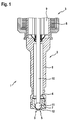
- FIG. 1 shows a sectional view of a fuel injection valve according to the invention 1.
- the fuel injection valve 1 is designed as a high-pressure injection valve for directly injecting fuel into a combustion chamber.
- FIG. 1 shows the structure for all embodiments.
- the fuel injection valve 1 comprises a housing 2, an actuator 3, a valve closing body 4 and a plurality of outlet openings 5.
- the housing 2 is composed of a base body 6 and a combustion chamber side insert 7.
- the combustion chamber facing side of the insert 7 is referred to as housing end face 12.
- the plurality of outlet openings 5 are arranged.
- the actuator 3 comprises an energizable coil 8 and a core 9.
- the valve closing body 4 is moved via the armature 9.
- the valve closing body 4 comprises a needle 10 and a ball 11. With a corresponding position of the needle 10, the ball 11 simultaneously closes all the outlet openings 5.
- FIGS. 2 to 7 is in each case an outlet opening surrounded by a dashed line.
- This edged exit opening shows a comparative example 14 according to the prior art.
- all outlet openings 5 are designed according to the invention on the housing end face 12.
- FIG. 2 shows a detail of the fuel injection valve 1 according to a first embodiment. Shown is a section of the combustion chamber facing housing end face 12. This housing end face 12 is designed dome-shaped. Shown is one of the several outlet openings 5. The combustion chamber is located in the upper region, accordingly, an injection direction 13 is shown for the fuel.
- the outlet opening 5 is composed of an injection hole 17 and a pre-stage chamber 18.
- the pre-stage chamber 18 is arranged on the combustion chamber side of the spray hole 17.
- the ring 15 is an integral part of the housing 2, in particular of the insert 7.
- the ring 15 has the combustion chamber side an annular end face 16 on the combustion chamber side of the precursor chamber 18.
- the edge at the transition to the annular end face 16 is referred to as edge 28. This edge 28 is formed as sharp as possible, to achieve a tearing of the flow here.
- the injection hole 17 has a first diameter 19.
- the precursor chamber 18 has a second diameter 20.
- the injection hole 17 extends over a first length 21.
- the pre-stage chamber 18 extends over a second length 22.
- the interior of the ring 15 extends over a third length 23.
- the ring 15 has a wall thickness 24.
- the second diameter 20 corresponds to an inner diameter of the ring 15. Furthermore, the second diameter 20 is formed substantially larger than the first diameter 19.
- the wall thickness 24 is as small as possible, preferably between 0.1 mm and 0.3 mm, formed in order to avoid deposition of the fuel on the annular end face 16 as far as possible.
- the third length 23 is between 0.1 mm and 0.5 mm.
- FIG. 3 shows in detail a second embodiment of the fuel injection valve 1.
- the annular end face 16 is inclined in the second embodiment relative to the tangent surface on the housing end face 12 by an angle ⁇ .
- the angle ⁇ is here at 10 °.
- the annular end face 16 is inclined outwards. As a result, a blow-off of deposits on the annular end face 16 is improved.
- FIG. 3 a radius 15 at the transition from the ring 15 to the housing end face 12th
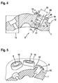
- FIGS. 4 and 5 show a detail of the fuel injection valve 1 according to a third embodiment.
- the annular end face 16 is not formed parallel to the tangent surface of the housing end face 12 in the third embodiment.
- the annular end face 16 is viewed in cross-section saddle-roof-shaped. The two faces of the annular end face 16 are inclined by the angle ⁇ , so that the tip or the gable roof shape is formed. This design of the annular end face 16 promotes the blowing off of deposits.
- FIGS. 6 and 7 show the fuel injection valve 1 according to a fourth embodiment.
- the annular end face 16 is designed like a saddle roof in the third embodiment.
- an inner diameter 27 of the ring 15 is increased. The inner diameter 27 is thus larger than the second diameter 20. This results in a step or a shoulder at the transition from the precursor chamber 18 to the interior of the ring 15th
Landscapes
- Engineering & Computer Science (AREA)
- Chemical & Material Sciences (AREA)
- Combustion & Propulsion (AREA)
- Mechanical Engineering (AREA)
- General Engineering & Computer Science (AREA)
- Physics & Mathematics (AREA)
- Electromagnetism (AREA)
- Fuel-Injection Apparatus (AREA)
Description
- Die vorliegende Erfindung betrifft ein Brennstoffeinspritzventil. Insbesondere wird ein Hochdruckeinspritzventil zum direkten Einspritzen von Brennstoff in einen Brennraum gezeigt.
- Bei vorbekannten Hochdruckeinspritzventilen, insbesondere mit Mehrlochaufbereitung, wird der Kraftstoff durch Spritzlöcher und Vorstufenkammern in den Brennraum abgespritzt. Die Vorstufenkammer endet dabei brennraumseitig bündig mit der brennraumzugewandten Stirnfläche des Gehäuses des Einspritzventils. Diese Stirnfläche wird auch als Injektorkuppe bezeichnet. Jede Einspritzung führt zu einer Benetzung des vorstufennahen Bereichs der Stirnfläche und zur erhöhten Partikelemission. Dabei polymerisieren Kraftstoffreste und bilden unter Einbindung der im Brennraum gebildeten Rußpartikel eine poröse Schicht. Diese poröse Schicht wirkt bei nachfolgenden Einspritzvorgängen wie ein "Schwamm" für den Kraftstoff und führt in der der Kompression nachfolgenden Unterdruckfase zur Ausdampfung und Partikelgenerierung.
- Aus der
DE 101 24 748 A1 ist bereits ein Brennstoffeinspritzventil, insbesondere ein Hochdruckeinspritzventil zum direkten Einspritzen von Brennstoff in einen Brennraum bekannt. Das Einspritzventil umfasst u.a. ein Gehäuse mit einer brennraumseitigen Gehäusestirnfläche, einen Aktor, einen von dem Aktor betätigbaren Ventilschließkörper und zumindest eine Austrittsöffnung in der Gehäusestirnfläche für den Brennstoff, wobei der Ventilschließkörper je nach Stellung die Austrittsöffnung verschließt oder frei gibt. Um die Austrittsöffnung herum ist brennraumseitig ein Ring auf der brennraumseitigen Gehäusestirnfläche ausgebildet, der die Austrittsöffnung über die Gehäusestirnfläche hinaus verlängert. Die Austrittsöffnung weist entweder einen inneren sich in Abströmrichtung des Brennstoffs verjüngenden trompetenförmigen oder einen inneren sich in Abströmrichtung des Brennstoffs verjüngenden tonnenartigen Strömungskanal auf. - Das erfindungsgemäße Brennstoffeinspritzventil mit den Merkmalen des Anspruchs 1 sieht einen Ring auf der Injektorkuppe, brennraumseitig der Vorstufenkammer vor. Dadurch wird die mit Kraftstoff benetzte Fläche drastisch reduziert und durch eine scharfkantige Ausführung des Ringes wird die im Spritzloch bzw. in der Vorstufenkammer verbleibende Kraftstofflamelle "abgeschnitten" und beim Schließvorgang der Austrittsöffnung wieder in das Brennstoffeinspritzventil zurückgezogen. Dadurch reduziert sich die verbleibende Masse. Die Ablagerungen auf der Ringstirnfläche des Ringes können leicht durch die Brennraumströmung abgeblasen werden. Der aufgesetzte Ring weist eine relativ geringe Masse auf und kann somit stark aufgeheizt werden, sodass es zu einer schnellen Ausdampfung verbleibender Kraftstoffreste in den Ablagerungen kommt, wodurch wiederum die Partikelbildung drastisch reduziert wird. All diese Vorteile werden erreicht durch das erfindungsgemäße Brennstoffeinspritzventil. Insbesondere handelt es sich hierbei um ein Hochdruckeinspritzventil zum direkten Einspritzen von Brennstoff in einen Brennraum. Das Einspritzventil umfasst (i) ein Gehäuse mit einer brennraumseitigen Gehäusestirnfläche, (ii) einen Aktor (iii), einen von dem Aktor betätigbaren Ventilschließkörper, und (iv) zumindest eine Austrittsöffnung in der Gehäusestirnfläche für den Brennstoff. Mittels des Aktors wird der Ventilschließkörper so bewegt, dass er wahlweise die Austrittsöffnung verschließt oder freigibt. Brennraumseitig um die Austrittsöffnung herum ist erfindungsgemäß ein Ring auf der brennraumseitigen Gehäusestirnfläche ausgebildet. Insbesondere ist dieser Ring integraler Bestandteil des Gehäuses. Der Ring kann auch als Wulst, Aufwurf oder Bund bezeichnet werden. Der Ring bzw. die Stirnfläche des Ringes stellt eine sehr kleine Fläche zur Ablagerung von Brennstoff dar, sodass eingangs erwähnte Probleme weitgehend vermieden werden.
- Die Unteransprüche zeigen bevorzugte Weiterbildungen der Erfindung.
- Die brennraumseitige bzw. die dem Brennraum zugewandte Gehäusestirnfläche, in der die Austrittsöffnung ausgebildet ist, ist insbesondere kuppelförmig gestaltet. Die Kuppelform erstreckt sich dabei in Richtung Brennraum. Vorteil dieser kuppelförmigen Ausgestaltung ist, dass auf der Kuppelform verteilt mehrere Austrittsöffnungen ausgebildet werden können. Der Ventilschließkörper ist insbesondere so gestaltet, dass er gleichzeitig je nach Stellung alle Austrittsöffnungen verschließt oder alle Austrittsöffnungen freigibt. Besonders bevorzugt ist vorgesehen, dass an jeder der Austrittsöffnungen ein erfindungsgemäßer Ring angeordnet ist.
- In vorteilhafter Ausbildung setzt sich die Austrittsöffnung aus einem Spritzloch mit einem ersten Durchmesser und einer sich brennraumseitig an das Spritzloch anschließenden Vorstufenkammer mit einem zweiten Durchmesser zusammen.
- Der zweite Durchmesser ist dabei größer als der erste Durchmesser. Der Brennstoff wird also durch das Spritzloch in die Vorstufenkammer eingespritzt. Aus dieser Vorstufenkammer geht der Brennstoff weiter in die Brennkammer der Brennkraftmaschine. Eben bei der Ausbildung der Austrittsöffnung mit einem Spritzloch und einer nachgeschalteten Vorstufenkammer gibt es bei vorbekannten Anordnungen die Problematik mit der Ablagerung von Brennstoff an der brennraumzugewandten Gehäusestirnfläche. Deshalb wird hier in vorteilhafter Weise der erfindungsgemäße Ring brennraumseitig der Vorstufenkammer verwendet.
- Für den Innendurchmesser des Ringes gibt es zwei bevorzugte Varianten. Zum einen kann der Innendurchmesser des Rings gleich dem zweiten Durchmesser sein. In diesem Fall stellt der Ring eine Verlängerung der Vorstufenkammer ohne Absätze dar.
- Alternativ dazu ist es möglich, dass der Innendurchmesser des Rings größer ist als der zweite Durchmesser. In diesem Fall gibt es eine Stufe oder einen Absatz am Übergang von der Vorstufenkammer zum Innenraum des Ringes.
- Der Ring weist eine brennraumseitige bzw. eine dem Brennraum zugewandte Ringstirnfläche auf. Auf dieser Ringstirnfläche kommt es zur Ablagerung vom Brennstoff. Um diese Ablagerung weitestgehend zu vermeiden, wird die Wandstärke des Rings möglichst klein gewählt. Darüber hinaus ist es vorteilhaft für das Wegblasen der Ablagerungen, wenn die Ringstirnfläche geneigt ist. Wenn die brennraumzugewandte Gehäusestirnfläche senkrecht zur Längsachse des Brennstoffeinspritzventils steht, kann die Neigung der Ringstirnfläche direkt in Bezug auf die Gehäusestirnfläche definiert werden. In bevorzugter Ausbildung ist jedoch vorgesehen, dass die Gehäusestirnfläche kuppelförmig ausgebildet ist. Bei der kuppelförmigen Ausbildung gibt es eine Tangentenfläche der Gehäusestirnfläche. Diese Tangentenfläche wird gebildet durch die Tangentenschar an der kuppelförmigen Gehäusestirnfläche. Die Neigung der Ringstirnfläche kann dementsprechend in Bezug zur Tangentenfläche definiert werden.
- Es ist bevorzugt vorgesehen, dass die gesamte Ringfläche gegenüber der Gehäusestirnfläche oder der Tangentenfläche eine Neigung aufweist. Der Neigungswinkel beträgt vorzugsweise zumindest 5 °, besonders vorzugsweise zumindest 10 °. Insbesondere ist die Ringstirnfläche nach außen geneigt. Dies bedeutet, dass der Ring innen höher ist als außen.
- Alternativ dazu ist es möglich, die Ringstirnfläche im Querschnitt betrachtet satteldachförmig auszugestalten. In diesem Fall unterteilt sich die Ringstirnfläche in zwei ringförmige Teilflächen die zu einander abgewinkelt sind. Auch hier ist es bevorzugt vorgesehen, die Neigungswinkel der einzelnen Teilflächen auf zumindest 5 °, vorzugsweise auf zumindest 10 ° zu setzen.
- Des Weiteren wird die Wandstärke des Rings möglichst gering gehalten, um Ablagerungen zu vermeiden. Insbesondere sollte die Wandstärke zwischen 0,1 mm und 0,3 mm liegen.
- Eine ausreichende Höhe des Rings muss sicherstellen, dass sich der Brennstoff auf der Ringstirnfläche ablagert jedoch nicht auf der umliegenden Gehäusestirnfläche. Deshalb sollte der Ring um 0,1 mm bis 0,5 mm über die Gehäusestirnfläche überstehen.
- Nachfolgend werden mehrere Ausführungsbeispiele der Erfindung unter Bezugnahme auf die begleitende Zeichnung im Detail beschrieben. Dabei zeigen:
- Figur 1
- eine Schnittansicht eines erfindungsgemäßen Brennstoffeinspritzventils gemäß allen Ausführungsbeispielen,
- Figur 2
- ein Detail des erfindungsgemäßen Brennstoffeinspritzventils gemäß einem ersten Ausführungsbeispiel,
- Figur 3
- ein Detail des erfindungsgemäßen Brennstoffeinspritzventils gemäß einem zweiten Ausführungsbeispiel,
- Figuren 4 und 5
- Details des erfindungsgemäßen Brennstoffeinspritzventils gemäß einem dritten Ausführungsbeispiel, und
- Figuren 6 und 7
- Details des erfindungsgemäßen Brennstoffeinspritzventils gemäß einem vierten Ausführungsbeispiel.
-
Figur 1 zeigt eine Schnittansicht eines erfindungsgemäßen Brennstoffeinspritzventils 1. Das Brennstoffeinspritzventil 1 ist ausgebildet als Hochdruckeinspritzventil zum direkten Einspritzen von Brennstoff in einen Brennraum.Figur 1 zeigt den Aufbau für alle Ausführungsbeispiele. - Das Brennstoffeinspritzventil 1 umfasst eine Gehäuse 2, einen Aktor 3, einen Ventilschließkörper 4 und mehrere Austrittsöffnungen 5. Das Gehäuse 2 setzt sich zusammen aus einem Grundkörper 6 und einem brennraumseitigen Einsatz 7. Die Brennraumzugewandte Seite des Einsatzes 7 wird als Gehäusestirnfläche 12 bezeichnet. In dieser Gehäusestirnfläche 12 sind die mehreren Austrittsöffnungen 5 angeordnet.
- Der Aktor 3 umfasst eine bestrombare Spule 8 und einen Kern 9. Durch Bestromen der Spule 8 wird über den Anker 9 der Ventilschließkörper 4 bewegt. Der Ventilschließkörper 4 umfasst eine Nadel 10 und eine Kugel 11. Bei entsprechender Stellung der Nadel 10 verschließt die Kugel 11 gleichzeitig alle Austrittsöffnungen 5.
- In den
Figuren 2 bis 7 ist jeweils eine Austrittsöffnung mit einer gestrichelten Linie umrandet. Diese umrandete Austrittsöffnung zeigt ein Vergleichsbeispiel 14 nach dem Stand der Technik. Tatsächlich sind alle Austrittsöffnungen 5 auf der Gehäusestirnfläche 12 erfindungsgemäß ausgestaltet. - Gleiche bzw. funktional gleiche Bauteile sind in allen Ausführungsbeispielen mit denselben Bezugszeichen versehen.
-
Figur 2 zeigt ein Detail des Brennstoffeinspritzventils 1 gemäß einem ersten Ausführungsbeispiel. Gezeigt ist ein Ausschnitt der brennraumzugewandten Gehäusestirnfläche 12. Diese Gehäusestirnfläche 12 ist kuppelförmig ausgestaltet. Gezeigt ist eine der mehreren Austrittsöffnungen 5. Der Brennraum befindet sich im oberen Bereich, demgemäß ist eine Einspritzrichtung 13 für den Brennstoff eingezeichnet. - Die Austrittsöffnung 5 setzt sich zusammen aus einem Spritzloch 17 und einer Vorstufenkammer 18. Die Vorstufenkammer 18 ist brennraumseitig des Spritzloches 17 angeordnet. Brennraumseitig der Vorstufenkammer 18 sitzt ein Ring 15 auf der Gehäusestirnfläche 12. Der Ring 15 ist integraler Bestandteil des Gehäuses 2, insbesondere des Einsatzes 7. Der Ring 15 weist brennraumseitig eine Ringstirnfläche 16 auf. Die Kante am Übergang zur Ringstirnfläche 16 wird als Kante 28 bezeichnet. Diese Kante 28 ist möglichst scharfkantig ausgebildet, um hier ein Abreißen der Strömung zu erreichen.
- Das Spritzloch 17 weist einen ersten Durchmesser 19 auf. Die Vorstufenkammer 18 weist einen zweiten Durchmesser 20 auf. Das Spritzloch 17 erstreckt sich über eine erste Länge 21. Die Vorstufenkammer 18 erstreckt sich über eine zweite Länge 22. Der Innenraum des Rings 15 erstreckt sich über eine dritte Länge 23. Der Ring 15 weist eine Wandstärke 24 auf.
- Im ersten Ausführungsbeispiel entspricht der zweite Durchmesser 20 einem Innendurchmesser des Rings 15. Des Weiteren ist der zweite Durchmesser 20 wesentlich größer ausgebildet als der erste Durchmesser 19.
- Die Wandstärke 24 wird möglichst klein, vorzugsweise zwischen 0,1 mm und 0,3 mm, ausgebildet, um eine Ablagerung des Brennstoffs auf der Ringstirnfläche 16 weitestgehend zu vermeiden.
- Die dritte Länge 23 liegt zwischen 0,1 mm und 0,5 mm.
-
Figur 3 zeigt im Detail ein zweites Ausführungsbeispiel des Brennstoffeinspritzventils 1. Im Unterschied zum ersten Ausführungsbeispiel, ist die Ringstirnfläche 16 im zweiten Ausführungsbeispiel gegenüber der Tangentenfläche auf die Gehäusestirnfläche 12 um einen Winkel α geneigt. Der Winkel α liegt hier bei 10 °. Die Ringstirnfläche 16 ist nach außen geneigt. Dadurch wird ein Abblasen von Ablagerungen auf der Ringstirnfläche 16 verbessert. Des Weiteren zeigtFigur 3 einen Radius 15 am Übergang vom Ring 15 zur Gehäusestirnfläche 12. - Die
Figuren 4 und 5 zeigen ein Detail des Brennstoffeinspritzventils 1 gemäß einem dritten Ausführungsbeispiel. Im Gegensatz zum ersten Ausführungsbeispiel wird im dritten Ausführungsbeispiel die Ringstirnfläche 16 nicht parallel zur Tangentenfläche der Gehäusestirnfläche 12 ausgebildet. Im dritten Ausführungsbeispiel ist die Ringstirnfläche 16 im Querschnitt betrachtet satteldachförmig. Die beiden Teilflächen der Ringstirnfläche 16 sind um den Winkel α geneigt, sodass die Spitze bzw. die Satteldachform entsteht. Diese Ausbildung der Ringstirnfläche 16 fördert das Abblasen von Ablagerungen. -
Figuren 6 und 7 zeigen das Brennstoffeinspritzventil 1 gemäß einem vierten Ausführungsbeispiel. Im vierten Ausführungsbeispiel ist die Ringstirnfläche 16 wie im dritten Ausführungsbeispiel satteldachförmig ausgestaltet. Des Weiteren wird im vierten Ausführungsbeispiel ein Innendurchmesser 27 des Rings 15 vergrößert. Der Innendurchmesser 27 ist somit größer als der zweite Durchmesser 20. Dadurch entstehen eine Stufe bzw. ein Absatz am Übergang von der Vorstufenkammer 18 zum Innenraum des Rings 15. - Diese unterschiedliche Ausbildung der Innendurchmesser am Ring 15 und der Vorstufenkammer 18 und die dadurch entstehende Kante am Übergang kann an allen Ausführungsbeispielen vorteilhaft angewendet werden und ist nicht abhängig von der satteldachförmigen Ausgestaltung der Ringstirnfläche 16.
Claims (9)
- Brennstoffeinspritzventil (1), insbesondere Hochdruckeinspritzventil zum direkten Einspritzen von Brennstoff in einen Brennraum, umfassend:ein Gehäuse (2) mit einer brennraumseitigen Gehäusestirnfläche (12),einen Aktor (3),einen von dem Aktor (3) betätigbaren Ventilschließkörper (4), undzumindest eine Austrittsöffnung (5) in der Gehäusestirnfläche (12) für den Brennstoff, wobei der Ventilschließkörper (4) je nach Stellung die Austrittsöffnung (5) verschließt oder frei gibt,einen brennraumseitig um die Austrittsöffnung (5) herum ausgebildeten Ring (15) auf der brennraumseitigen Gehäusestirnfläche (12),dadurch gekennzeichnet,dass die Austrittsöffnung (5) ein Spritzloch (17) mit einem ersten Durchmesser (19) und eine sich brennraumseitig an das Spritzloch (17) anschließende Vorstufenkammer (18) mit einem zweiten Durchmesser (20) umfasst, wobei der zweite Durchmesser (20) größer ist als der erste Durchmesser (19) und die Vorstufenkammer (18) in Strömungsrichtung gesehen bereits vor der Gehäusestirnfläche (12) beginnt und wobei ein Innendurchmesser (27) des Rings (15) gleich dem zweiten Durchmesser (20) ist oder noch größer ist als der zweite Durchmesser (20).
- Brennstoffeinspritzventil nach Anspruch 1, dadurch gekennzeichnet, dass die brennraumseitige Gehäusestirnfläche (12) kuppelförmig ausgebildet ist.
- Brennstoffeinspritzventil nach einem der vorhergehenden Ansprüche, dadurch gekennzeichnet, dass auf der brennraumseitigen Gehäusestirnfläche (12) mehrere Austrittsöffnungen (5) mit jeweils einem Ring (15) angeordnet sind.
- Brennstoffeinspritzventil nach einem der vorhergehenden Ansprüche, dadurch gekennzeichnet, dass eine brennraumseitige Ringstirnfläche (16) des Rings (15) parallel zur Gehäusestirnfläche (12) oder parallel zur Tangentenfläche der Gehäusestirnfläche (12) angeordnet ist.
- Brennstoffeinspritzventil nach einem der Ansprüche 1 bis 3, dadurch gekennzeichnet, dass die brennraumseitige Ringstirnfläche (16) des Rings (15) bezüglich der Gehäusestirnfläche (12) oder bezüglich der Tangentenfläche der Gehäusestirnfläche (12) geneigt ist.
- Brennstoffeinspritzventil nach Anspruch 5, dadurch gekennzeichnet, dass die brennraumseitige Ringstirnfläche (16) des Rings (15) im Querschnitt betrachtet satteldachförmig ausgebildet ist.
- Brennstoffeinspritzventil nach einem der Ansprüche 5 oder 6, dadurch gekennzeichnet, dass die brennraumseitige Ringstirnfläche (16) des Rings (15) bezüglich der Gehäusestirnfläche (12) oder bezüglich der Tangentenfläche der Gehäusestirnfläche (12) um zumindest 5°, vorzugsweise um zumindest 10°, geneigt ist.
- Brennstoffeinspritzventil nach einem der vorhergehenden Ansprüche, dadurch gekennzeichnet, dass eine Wandstärke (24) des Rings (15) zwischen 0,1mm und 0,3mm liegt.
- Brennstoffeinspritzventil nach einem der vorhergehenden Ansprüche, dadurch gekennzeichnet, dass der Ring (15) von der Gehäusestirnfläche (12) um 0,1mm bis 0,5mm übersteht.
Applications Claiming Priority (2)
| Application Number | Priority Date | Filing Date | Title |
|---|---|---|---|
| DE201210209326 DE102012209326A1 (de) | 2012-06-01 | 2012-06-01 | Brennstoffeinspritzventil |
| PCT/EP2013/060757 WO2013178549A1 (de) | 2012-06-01 | 2013-05-24 | Brennstoffeinspritzventil |
Publications (2)
| Publication Number | Publication Date |
|---|---|
| EP2855917A1 EP2855917A1 (de) | 2015-04-08 |
| EP2855917B1 true EP2855917B1 (de) | 2016-10-19 |
Family
ID=48536844
Family Applications (1)
| Application Number | Title | Priority Date | Filing Date |
|---|---|---|---|
| EP13725637.6A Not-in-force EP2855917B1 (de) | 2012-06-01 | 2013-05-24 | Brennstoffeinspritzventil |
Country Status (6)
| Country | Link |
|---|---|
| US (1) | US9599084B2 (de) |
| EP (1) | EP2855917B1 (de) |
| JP (1) | JP6077648B2 (de) |
| KR (1) | KR102089242B1 (de) |
| DE (1) | DE102012209326A1 (de) |
| WO (1) | WO2013178549A1 (de) |
Families Citing this family (5)
| Publication number | Priority date | Publication date | Assignee | Title |
|---|---|---|---|---|
| JP6020380B2 (ja) * | 2013-08-02 | 2016-11-02 | 株式会社デンソー | 燃料噴射弁 |
| DE102013225948A1 (de) | 2013-12-13 | 2015-06-18 | Continental Automotive Gmbh | Düsenkopf und Fluid-Einspritzventil |
| JP6292188B2 (ja) * | 2015-04-09 | 2018-03-14 | 株式会社デンソー | 燃料噴射装置 |
| WO2019030078A1 (en) * | 2017-08-08 | 2019-02-14 | Robert Bosch Gmbh | FUEL INJECTOR NOZZLE |
| GB2577251A (en) * | 2018-09-18 | 2020-03-25 | Ford Global Tech Llc | Diesel injectors and method of manufacturing diesel injectors |
Family Cites Families (43)
| Publication number | Priority date | Publication date | Assignee | Title |
|---|---|---|---|---|
| US4245789A (en) * | 1979-05-03 | 1981-01-20 | General Motors Corporation | Electromagnetic fuel injector |
| DE3116954C2 (de) * | 1981-04-29 | 1993-10-21 | Bosch Gmbh Robert | Kraftstoffeinspritzventil für Brennkraftmaschinen |
| JPS59139578U (ja) * | 1983-03-10 | 1984-09-18 | 日産自動車株式会社 | ホ−ル型燃料噴射弁 |
| DE3408012A1 (de) * | 1984-03-05 | 1985-09-05 | Gerhard Dipl.-Ing. Warren Mich. Mesenich | Elektromagnetisches einspritzventil |
| DE3427526A1 (de) | 1984-07-26 | 1986-02-06 | Robert Bosch Gmbh, 7000 Stuttgart | Elektromagnetisch betaetigbares ventil |
| JPS62116164U (de) * | 1986-01-14 | 1987-07-23 | ||
| DE3733604A1 (de) * | 1987-10-05 | 1989-04-13 | Bosch Gmbh Robert | Lochkoerper fuer eine kraftstoffeinspritzventil |
| JPH04246274A (ja) | 1991-02-01 | 1992-09-02 | Shinnenshiyou Syst Kenkyusho:Kk | 直接噴射式ディーゼル機関の燃料噴射装置 |
| JPH08232813A (ja) * | 1995-02-27 | 1996-09-10 | Aisan Ind Co Ltd | インジェクタ |
| JPH09236062A (ja) * | 1996-02-27 | 1997-09-09 | Zexel Corp | 電磁式燃料噴射弁のカーボンデポジット防止装置 |
| JPH10252612A (ja) * | 1997-03-07 | 1998-09-22 | Zexel Corp | 燃料噴射ノズル |
| JP3771361B2 (ja) * | 1997-11-26 | 2006-04-26 | 株式会社日立製作所 | 燃料噴射弁 |
| JPH11200998A (ja) * | 1998-01-19 | 1999-07-27 | Denso Corp | 流体噴射ノズル |
| DE19815789A1 (de) * | 1998-04-08 | 1999-10-14 | Bosch Gmbh Robert | Brennstoffeinspritzventil |
| DE19815918A1 (de) * | 1998-04-09 | 1999-10-21 | Man B & W Diesel As | Brennstoffeinspritzvorrichtung |
| JP3466480B2 (ja) * | 1998-07-06 | 2003-11-10 | 日本碍子株式会社 | 液体吐出装置用ノズル及びその製造方法 |
| JP2000064929A (ja) * | 1998-08-24 | 2000-03-03 | Mitsubishi Electric Corp | 燃料噴射弁 |
| JP2976973B1 (ja) * | 1998-09-29 | 1999-11-10 | トヨタ自動車株式会社 | 内燃機関用燃料噴射弁 |
| JP2000227063A (ja) * | 1998-12-04 | 2000-08-15 | Hitachi Ltd | 燃料噴射弁、燃料噴射装置及び内燃機関 |
| DE19907899A1 (de) * | 1999-02-24 | 2000-08-31 | Bosch Gmbh Robert | Brennstoffeinspritzventil |
| DE19937961A1 (de) * | 1999-08-11 | 2001-02-15 | Bosch Gmbh Robert | Brennstoffeinspritzventil und Verfahren zur Herstellung von Austrittsöffnungen an Ventilen |
| JP2001099035A (ja) * | 1999-09-30 | 2001-04-10 | Hitachi Ltd | 燃料噴射用ノズル及びその製造方法 |
| JP3651338B2 (ja) * | 1999-12-15 | 2005-05-25 | 株式会社日立製作所 | 筒内燃料噴射弁およびこれを搭載した内燃機関 |
| JP2002206469A (ja) * | 2001-01-12 | 2002-07-26 | Hitachi Ltd | 燃料噴射弁およびこれを搭載した内燃機関 |
| DE10118163B4 (de) * | 2001-04-11 | 2007-04-19 | Robert Bosch Gmbh | Brennstoffeinspritzventil |
| DE10120462A1 (de) * | 2001-04-26 | 2002-10-31 | Bosch Gmbh Robert | Brennstoffeinspritzventil |
| DE10124748A1 (de) * | 2001-05-21 | 2003-02-27 | Bosch Gmbh Robert | Brennstoffeinspritzventil |
| JP3882623B2 (ja) * | 2002-01-28 | 2007-02-21 | 株式会社デンソー | 燃料噴射ノズル |
| DE10307931A1 (de) * | 2003-02-25 | 2004-10-28 | Robert Bosch Gmbh | Brennstoffeinspritzventil |
| DE10319694A1 (de) * | 2003-05-02 | 2004-12-02 | Robert Bosch Gmbh | Brennstoffeinspritzventil |
| JP2005098160A (ja) | 2003-09-24 | 2005-04-14 | Toyota Central Res & Dev Lab Inc | 筒内直噴式内燃機関の燃料噴射弁 |
| JP2006132434A (ja) * | 2004-11-05 | 2006-05-25 | Denso Corp | 噴孔部材、燃料噴射弁、および噴孔部材の製造方法 |
| US7438241B2 (en) * | 2004-11-05 | 2008-10-21 | Visteon Global Technologies, Inc. | Low pressure fuel injector nozzle |
| JP4185045B2 (ja) * | 2004-12-22 | 2008-11-19 | 株式会社日立製作所 | 燃料噴射弁 |
| US7712680B2 (en) * | 2006-01-30 | 2010-05-11 | Sono-Tek Corporation | Ultrasonic atomizing nozzle and method |
| JP4595960B2 (ja) * | 2007-05-10 | 2010-12-08 | 株式会社デンソー | 燃料噴射弁 |
| JP4548448B2 (ja) * | 2007-05-24 | 2010-09-22 | 株式会社デンソー | 燃料噴射弁 |
| JP4627783B2 (ja) * | 2008-03-31 | 2011-02-09 | 日立オートモティブシステムズ株式会社 | 燃料噴射弁及びオリフィスの加工方法 |
| JP4610631B2 (ja) * | 2008-05-01 | 2011-01-12 | 三菱電機株式会社 | 燃料噴射弁 |
| JP5559962B2 (ja) * | 2008-09-05 | 2014-07-23 | 日立オートモティブシステムズ株式会社 | 燃料噴射弁及びノズルの加工方法 |
| JP4988791B2 (ja) * | 2009-06-18 | 2012-08-01 | 日立オートモティブシステムズ株式会社 | 燃料噴射弁 |
| JP2011179429A (ja) * | 2010-03-02 | 2011-09-15 | Toyota Motor Corp | 燃料噴射弁 |
| CN103703242B (zh) * | 2011-08-03 | 2016-06-01 | 日立汽车系统株式会社 | 燃料喷射阀 |
-
2012
- 2012-06-01 DE DE201210209326 patent/DE102012209326A1/de not_active Withdrawn
-
2013
- 2013-05-24 EP EP13725637.6A patent/EP2855917B1/de not_active Not-in-force
- 2013-05-24 WO PCT/EP2013/060757 patent/WO2013178549A1/de not_active Ceased
- 2013-05-24 KR KR1020147033527A patent/KR102089242B1/ko not_active Expired - Fee Related
- 2013-05-24 JP JP2015514437A patent/JP6077648B2/ja not_active Expired - Fee Related
- 2013-05-24 US US14/404,724 patent/US9599084B2/en not_active Expired - Fee Related
Also Published As
| Publication number | Publication date |
|---|---|
| US20150115068A1 (en) | 2015-04-30 |
| KR20150018525A (ko) | 2015-02-23 |
| DE102012209326A1 (de) | 2013-12-05 |
| JP2015518111A (ja) | 2015-06-25 |
| US9599084B2 (en) | 2017-03-21 |
| EP2855917A1 (de) | 2015-04-08 |
| WO2013178549A1 (de) | 2013-12-05 |
| KR102089242B1 (ko) | 2020-03-16 |
| JP6077648B2 (ja) | 2017-02-08 |
Similar Documents
| Publication | Publication Date | Title |
|---|---|---|
| EP1076772B1 (de) | Kraftstoffeinspritzdüse für eine brennkraftmaschine | |
| DE69806509T2 (de) | Flache nadel für ein druckbeaufschlagtes dralleinspritzventil | |
| DE3841142A1 (de) | Einspritzventil | |
| EP2087228B1 (de) | Brennstoffeinspritzventil | |
| WO2003031806A1 (de) | Brennstoffeinspritzventil | |
| EP2855917A1 (de) | Brennstoffeinspritzventil | |
| EP2521853B1 (de) | Brennstoffeinspritzventil | |
| DE102006000407B4 (de) | Kraftstoffeinspritzdüse mit mehreren Einspritzlöchern | |
| DE102010032050B4 (de) | Düsenkörper mit Sackloch | |
| EP1408231B1 (de) | Einspritzvorrichtung zum Einspritzen von Kraftstoff | |
| DE102016224084B4 (de) | Kraftstoffinjektor | |
| WO2015055632A1 (de) | Einspritzvorrichtung | |
| DE10142299A1 (de) | Brennstoffeinspritzsystem | |
| WO2017114634A1 (de) | Brennstoffeinspritzventil | |
| EP1481159B1 (de) | Brennstoffeinspritzventil | |
| DE102017218224A1 (de) | Ventil zum Zumessen eines Fluids, insbesondere Brennstoffeinspritzventil | |
| DE102016222239A1 (de) | Injektor zum Einspritzen eines Fluids mit verbessertem Spraybild | |
| DE102017205665A1 (de) | Injektor zum Einbringen eines Fluids mit verbesserter Strahlaufbereitung | |
| EP2914839A1 (de) | Düsenbaugruppe für einen kraftstoffinjektor und kraftstoffinjektor | |
| WO2015052031A1 (de) | Düsenkörper für ein einspritzventil und einspritzventil | |
| DE102010062808A1 (de) | Düsenkörper mit konischem Einspritzloch | |
| DE102024210666A1 (de) | Injektor zum Einblasen eines gasförmigen Mediums | |
| DE102025137518A1 (de) | Injektor zum Einblasen eines gasförmigen Mediums | |
| EP3098434B1 (de) | Kraftstoffeinspritzsystem | |
| WO2016102239A1 (de) | Düsenkörper und fluid-einspritzventil |
Legal Events
| Date | Code | Title | Description |
|---|---|---|---|
| PUAI | Public reference made under article 153(3) epc to a published international application that has entered the european phase |
Free format text: ORIGINAL CODE: 0009012 |
|
| 17P | Request for examination filed |
Effective date: 20150105 |
|
| AK | Designated contracting states |
Kind code of ref document: A1 Designated state(s): AL AT BE BG CH CY CZ DE DK EE ES FI FR GB GR HR HU IE IS IT LI LT LU LV MC MK MT NL NO PL PT RO RS SE SI SK SM TR |
|
| AX | Request for extension of the european patent |
Extension state: BA ME |
|
| DAX | Request for extension of the european patent (deleted) | ||
| GRAP | Despatch of communication of intention to grant a patent |
Free format text: ORIGINAL CODE: EPIDOSNIGR1 |
|
| INTG | Intention to grant announced |
Effective date: 20160729 |
|
| GRAS | Grant fee paid |
Free format text: ORIGINAL CODE: EPIDOSNIGR3 |
|
| GRAA | (expected) grant |
Free format text: ORIGINAL CODE: 0009210 |
|
| AK | Designated contracting states |
Kind code of ref document: B1 Designated state(s): AL AT BE BG CH CY CZ DE DK EE ES FI FR GB GR HR HU IE IS IT LI LT LU LV MC MK MT NL NO PL PT RO RS SE SI SK SM TR |
|
| REG | Reference to a national code |
Ref country code: GB Ref legal event code: FG4D Free format text: NOT ENGLISH |
|
| REG | Reference to a national code |
Ref country code: CH Ref legal event code: EP |
|
| REG | Reference to a national code |
Ref country code: AT Ref legal event code: REF Ref document number: 838573 Country of ref document: AT Kind code of ref document: T Effective date: 20161115 |
|
| REG | Reference to a national code |
Ref country code: IE Ref legal event code: FG4D Free format text: LANGUAGE OF EP DOCUMENT: GERMAN |
|
| REG | Reference to a national code |
Ref country code: DE Ref legal event code: R096 Ref document number: 502013005044 Country of ref document: DE |
|
| REG | Reference to a national code |
Ref country code: NL Ref legal event code: MP Effective date: 20161019 |
|
| REG | Reference to a national code |
Ref country code: LT Ref legal event code: MG4D |
|
| PG25 | Lapsed in a contracting state [announced via postgrant information from national office to epo] |
Ref country code: LV Free format text: LAPSE BECAUSE OF FAILURE TO SUBMIT A TRANSLATION OF THE DESCRIPTION OR TO PAY THE FEE WITHIN THE PRESCRIBED TIME-LIMIT Effective date: 20161019 |
|
| PG25 | Lapsed in a contracting state [announced via postgrant information from national office to epo] |
Ref country code: NO Free format text: LAPSE BECAUSE OF FAILURE TO SUBMIT A TRANSLATION OF THE DESCRIPTION OR TO PAY THE FEE WITHIN THE PRESCRIBED TIME-LIMIT Effective date: 20170119 Ref country code: SE Free format text: LAPSE BECAUSE OF FAILURE TO SUBMIT A TRANSLATION OF THE DESCRIPTION OR TO PAY THE FEE WITHIN THE PRESCRIBED TIME-LIMIT Effective date: 20161019 Ref country code: GR Free format text: LAPSE BECAUSE OF FAILURE TO SUBMIT A TRANSLATION OF THE DESCRIPTION OR TO PAY THE FEE WITHIN THE PRESCRIBED TIME-LIMIT Effective date: 20170120 Ref country code: LT Free format text: LAPSE BECAUSE OF FAILURE TO SUBMIT A TRANSLATION OF THE DESCRIPTION OR TO PAY THE FEE WITHIN THE PRESCRIBED TIME-LIMIT Effective date: 20161019 |
|
| REG | Reference to a national code |
Ref country code: FR Ref legal event code: PLFP Year of fee payment: 5 |
|
| PG25 | Lapsed in a contracting state [announced via postgrant information from national office to epo] |
Ref country code: PL Free format text: LAPSE BECAUSE OF FAILURE TO SUBMIT A TRANSLATION OF THE DESCRIPTION OR TO PAY THE FEE WITHIN THE PRESCRIBED TIME-LIMIT Effective date: 20161019 Ref country code: NL Free format text: LAPSE BECAUSE OF FAILURE TO SUBMIT A TRANSLATION OF THE DESCRIPTION OR TO PAY THE FEE WITHIN THE PRESCRIBED TIME-LIMIT Effective date: 20161019 Ref country code: FI Free format text: LAPSE BECAUSE OF FAILURE TO SUBMIT A TRANSLATION OF THE DESCRIPTION OR TO PAY THE FEE WITHIN THE PRESCRIBED TIME-LIMIT Effective date: 20161019 Ref country code: ES Free format text: LAPSE BECAUSE OF FAILURE TO SUBMIT A TRANSLATION OF THE DESCRIPTION OR TO PAY THE FEE WITHIN THE PRESCRIBED TIME-LIMIT Effective date: 20161019 Ref country code: RS Free format text: LAPSE BECAUSE OF FAILURE TO SUBMIT A TRANSLATION OF THE DESCRIPTION OR TO PAY THE FEE WITHIN THE PRESCRIBED TIME-LIMIT Effective date: 20161019 Ref country code: IS Free format text: LAPSE BECAUSE OF FAILURE TO SUBMIT A TRANSLATION OF THE DESCRIPTION OR TO PAY THE FEE WITHIN THE PRESCRIBED TIME-LIMIT Effective date: 20170219 Ref country code: HR Free format text: LAPSE BECAUSE OF FAILURE TO SUBMIT A TRANSLATION OF THE DESCRIPTION OR TO PAY THE FEE WITHIN THE PRESCRIBED TIME-LIMIT Effective date: 20161019 Ref country code: PT Free format text: LAPSE BECAUSE OF FAILURE TO SUBMIT A TRANSLATION OF THE DESCRIPTION OR TO PAY THE FEE WITHIN THE PRESCRIBED TIME-LIMIT Effective date: 20170220 |
|
| REG | Reference to a national code |
Ref country code: DE Ref legal event code: R097 Ref document number: 502013005044 Country of ref document: DE |
|
| PG25 | Lapsed in a contracting state [announced via postgrant information from national office to epo] |
Ref country code: DK Free format text: LAPSE BECAUSE OF FAILURE TO SUBMIT A TRANSLATION OF THE DESCRIPTION OR TO PAY THE FEE WITHIN THE PRESCRIBED TIME-LIMIT Effective date: 20161019 Ref country code: RO Free format text: LAPSE BECAUSE OF FAILURE TO SUBMIT A TRANSLATION OF THE DESCRIPTION OR TO PAY THE FEE WITHIN THE PRESCRIBED TIME-LIMIT Effective date: 20161019 Ref country code: EE Free format text: LAPSE BECAUSE OF FAILURE TO SUBMIT A TRANSLATION OF THE DESCRIPTION OR TO PAY THE FEE WITHIN THE PRESCRIBED TIME-LIMIT Effective date: 20161019 Ref country code: SK Free format text: LAPSE BECAUSE OF FAILURE TO SUBMIT A TRANSLATION OF THE DESCRIPTION OR TO PAY THE FEE WITHIN THE PRESCRIBED TIME-LIMIT Effective date: 20161019 Ref country code: CZ Free format text: LAPSE BECAUSE OF FAILURE TO SUBMIT A TRANSLATION OF THE DESCRIPTION OR TO PAY THE FEE WITHIN THE PRESCRIBED TIME-LIMIT Effective date: 20161019 |
|
| PLBE | No opposition filed within time limit |
Free format text: ORIGINAL CODE: 0009261 |
|
| STAA | Information on the status of an ep patent application or granted ep patent |
Free format text: STATUS: NO OPPOSITION FILED WITHIN TIME LIMIT |
|
| PG25 | Lapsed in a contracting state [announced via postgrant information from national office to epo] |
Ref country code: BG Free format text: LAPSE BECAUSE OF FAILURE TO SUBMIT A TRANSLATION OF THE DESCRIPTION OR TO PAY THE FEE WITHIN THE PRESCRIBED TIME-LIMIT Effective date: 20170119 Ref country code: LU Free format text: LAPSE BECAUSE OF NON-PAYMENT OF DUE FEES Effective date: 20170531 Ref country code: SM Free format text: LAPSE BECAUSE OF FAILURE TO SUBMIT A TRANSLATION OF THE DESCRIPTION OR TO PAY THE FEE WITHIN THE PRESCRIBED TIME-LIMIT Effective date: 20161019 |
|
| 26N | No opposition filed |
Effective date: 20170720 |
|
| PG25 | Lapsed in a contracting state [announced via postgrant information from national office to epo] |
Ref country code: SI Free format text: LAPSE BECAUSE OF FAILURE TO SUBMIT A TRANSLATION OF THE DESCRIPTION OR TO PAY THE FEE WITHIN THE PRESCRIBED TIME-LIMIT Effective date: 20161019 |
|
| REG | Reference to a national code |
Ref country code: CH Ref legal event code: PL |
|
| PG25 | Lapsed in a contracting state [announced via postgrant information from national office to epo] |
Ref country code: MC Free format text: LAPSE BECAUSE OF FAILURE TO SUBMIT A TRANSLATION OF THE DESCRIPTION OR TO PAY THE FEE WITHIN THE PRESCRIBED TIME-LIMIT Effective date: 20161019 |
|
| REG | Reference to a national code |
Ref country code: IE Ref legal event code: MM4A |
|
| PG25 | Lapsed in a contracting state [announced via postgrant information from national office to epo] |
Ref country code: CH Free format text: LAPSE BECAUSE OF NON-PAYMENT OF DUE FEES Effective date: 20170531 Ref country code: LI Free format text: LAPSE BECAUSE OF NON-PAYMENT OF DUE FEES Effective date: 20170531 |
|
| PG25 | Lapsed in a contracting state [announced via postgrant information from national office to epo] |
Ref country code: LU Free format text: LAPSE BECAUSE OF NON-PAYMENT OF DUE FEES Effective date: 20170524 |
|
| REG | Reference to a national code |
Ref country code: BE Ref legal event code: MM Effective date: 20170531 |
|
| PG25 | Lapsed in a contracting state [announced via postgrant information from national office to epo] |
Ref country code: IE Free format text: LAPSE BECAUSE OF NON-PAYMENT OF DUE FEES Effective date: 20170524 |
|
| REG | Reference to a national code |
Ref country code: FR Ref legal event code: PLFP Year of fee payment: 6 |
|
| PG25 | Lapsed in a contracting state [announced via postgrant information from national office to epo] |
Ref country code: BE Free format text: LAPSE BECAUSE OF NON-PAYMENT OF DUE FEES Effective date: 20170531 |
|
| PG25 | Lapsed in a contracting state [announced via postgrant information from national office to epo] |
Ref country code: MT Free format text: LAPSE BECAUSE OF FAILURE TO SUBMIT A TRANSLATION OF THE DESCRIPTION OR TO PAY THE FEE WITHIN THE PRESCRIBED TIME-LIMIT Effective date: 20161019 |
|
| PG25 | Lapsed in a contracting state [announced via postgrant information from national office to epo] |
Ref country code: HU Free format text: LAPSE BECAUSE OF FAILURE TO SUBMIT A TRANSLATION OF THE DESCRIPTION OR TO PAY THE FEE WITHIN THE PRESCRIBED TIME-LIMIT; INVALID AB INITIO Effective date: 20130524 |
|
| REG | Reference to a national code |
Ref country code: AT Ref legal event code: MM01 Ref document number: 838573 Country of ref document: AT Kind code of ref document: T Effective date: 20180524 |
|
| PGFP | Annual fee paid to national office [announced via postgrant information from national office to epo] |
Ref country code: IT Payment date: 20190521 Year of fee payment: 7 |
|
| PGFP | Annual fee paid to national office [announced via postgrant information from national office to epo] |
Ref country code: FR Payment date: 20190521 Year of fee payment: 7 |
|
| PG25 | Lapsed in a contracting state [announced via postgrant information from national office to epo] |
Ref country code: CY Free format text: LAPSE BECAUSE OF FAILURE TO SUBMIT A TRANSLATION OF THE DESCRIPTION OR TO PAY THE FEE WITHIN THE PRESCRIBED TIME-LIMIT Effective date: 20161019 Ref country code: AT Free format text: LAPSE BECAUSE OF NON-PAYMENT OF DUE FEES Effective date: 20180524 |
|
| PGFP | Annual fee paid to national office [announced via postgrant information from national office to epo] |
Ref country code: GB Payment date: 20190523 Year of fee payment: 7 |
|
| PG25 | Lapsed in a contracting state [announced via postgrant information from national office to epo] |
Ref country code: MK Free format text: LAPSE BECAUSE OF FAILURE TO SUBMIT A TRANSLATION OF THE DESCRIPTION OR TO PAY THE FEE WITHIN THE PRESCRIBED TIME-LIMIT Effective date: 20161019 |
|
| PG25 | Lapsed in a contracting state [announced via postgrant information from national office to epo] |
Ref country code: TR Free format text: LAPSE BECAUSE OF FAILURE TO SUBMIT A TRANSLATION OF THE DESCRIPTION OR TO PAY THE FEE WITHIN THE PRESCRIBED TIME-LIMIT Effective date: 20161019 |
|
| PG25 | Lapsed in a contracting state [announced via postgrant information from national office to epo] |
Ref country code: AL Free format text: LAPSE BECAUSE OF FAILURE TO SUBMIT A TRANSLATION OF THE DESCRIPTION OR TO PAY THE FEE WITHIN THE PRESCRIBED TIME-LIMIT Effective date: 20161019 |
|
| GBPC | Gb: european patent ceased through non-payment of renewal fee |
Effective date: 20200524 |
|
| PG25 | Lapsed in a contracting state [announced via postgrant information from national office to epo] |
Ref country code: GB Free format text: LAPSE BECAUSE OF NON-PAYMENT OF DUE FEES Effective date: 20200524 Ref country code: FR Free format text: LAPSE BECAUSE OF NON-PAYMENT OF DUE FEES Effective date: 20200531 |
|
| PG25 | Lapsed in a contracting state [announced via postgrant information from national office to epo] |
Ref country code: IT Free format text: LAPSE BECAUSE OF NON-PAYMENT OF DUE FEES Effective date: 20200524 |
|
| PGFP | Annual fee paid to national office [announced via postgrant information from national office to epo] |
Ref country code: DE Payment date: 20220725 Year of fee payment: 10 |
|
| REG | Reference to a national code |
Ref country code: DE Ref legal event code: R119 Ref document number: 502013005044 Country of ref document: DE |
|
| PG25 | Lapsed in a contracting state [announced via postgrant information from national office to epo] |
Ref country code: DE Free format text: LAPSE BECAUSE OF NON-PAYMENT OF DUE FEES Effective date: 20231201 |