EP2855154B1 - Procédé de commande d'une imprimante couleur ou d'un copieur couleur - Google Patents
Procédé de commande d'une imprimante couleur ou d'un copieur couleur Download PDFInfo
- Publication number
- EP2855154B1 EP2855154B1 EP13732353.1A EP13732353A EP2855154B1 EP 2855154 B1 EP2855154 B1 EP 2855154B1 EP 13732353 A EP13732353 A EP 13732353A EP 2855154 B1 EP2855154 B1 EP 2855154B1
- Authority
- EP
- European Patent Office
- Prior art keywords
- color
- control field
- color value
- determined
- control
- Prior art date
- Legal status (The legal status is an assumption and is not a legal conclusion. Google has not performed a legal analysis and makes no representation as to the accuracy of the status listed.)
- Active
Links
- 238000000034 method Methods 0.000 title claims description 36
- 238000000926 separation method Methods 0.000 claims description 81
- 239000003086 colorant Substances 0.000 claims description 47
- 239000000758 substrate Substances 0.000 claims description 11
- 239000000463 material Substances 0.000 description 17
- 238000012544 monitoring process Methods 0.000 description 9
- 238000010586 diagram Methods 0.000 description 7
- 239000000976 ink Substances 0.000 description 7
- 238000005259 measurement Methods 0.000 description 7
- 230000003287 optical effect Effects 0.000 description 4
- 230000007423 decrease Effects 0.000 description 3
- 230000011514 reflex Effects 0.000 description 3
- 230000003595 spectral effect Effects 0.000 description 3
- 238000012360 testing method Methods 0.000 description 3
- 238000012546 transfer Methods 0.000 description 3
- 230000001419 dependent effect Effects 0.000 description 2
- 238000009826 distribution Methods 0.000 description 2
- 238000002474 experimental method Methods 0.000 description 2
- XOFYZVNMUHMLCC-ZPOLXVRWSA-N prednisone Chemical compound O=C1C=C[C@]2(C)[C@H]3C(=O)C[C@](C)([C@@](CC4)(O)C(=O)CO)[C@@H]4[C@@H]3CCC2=C1 XOFYZVNMUHMLCC-ZPOLXVRWSA-N 0.000 description 2
- 238000012935 Averaging Methods 0.000 description 1
- 239000004642 Polyimide Substances 0.000 description 1
- 230000006978 adaptation Effects 0.000 description 1
- 230000033228 biological regulation Effects 0.000 description 1
- 238000001739 density measurement Methods 0.000 description 1
- 238000001514 detection method Methods 0.000 description 1
- 238000011161 development Methods 0.000 description 1
- 230000018109 developmental process Effects 0.000 description 1
- 238000006073 displacement reaction Methods 0.000 description 1
- 230000000694 effects Effects 0.000 description 1
- 239000000284 extract Substances 0.000 description 1
- 238000009434 installation Methods 0.000 description 1
- 239000000203 mixture Substances 0.000 description 1
- 238000005457 optimization Methods 0.000 description 1
- 229920001721 polyimide Polymers 0.000 description 1
- 238000012216 screening Methods 0.000 description 1
- 239000007787 solid Substances 0.000 description 1
Images


Classifications
-
- H—ELECTRICITY
- H04—ELECTRIC COMMUNICATION TECHNIQUE
- H04N—PICTORIAL COMMUNICATION, e.g. TELEVISION
- H04N1/00—Scanning, transmission or reproduction of documents or the like, e.g. facsimile transmission; Details thereof
- H04N1/46—Colour picture communication systems
- H04N1/56—Processing of colour picture signals
- H04N1/60—Colour correction or control
- H04N1/603—Colour correction or control controlled by characteristics of the picture signal generator or the picture reproducer
- H04N1/6033—Colour correction or control controlled by characteristics of the picture signal generator or the picture reproducer using test pattern analysis
- H04N1/6044—Colour correction or control controlled by characteristics of the picture signal generator or the picture reproducer using test pattern analysis involving a sensor integrated in the machine or otherwise specifically adapted to read the test pattern
-
- H—ELECTRICITY
- H04—ELECTRIC COMMUNICATION TECHNIQUE
- H04N—PICTORIAL COMMUNICATION, e.g. TELEVISION
- H04N1/00—Scanning, transmission or reproduction of documents or the like, e.g. facsimile transmission; Details thereof
- H04N1/46—Colour picture communication systems
- H04N1/56—Processing of colour picture signals
- H04N1/58—Edge or detail enhancement; Noise or error suppression, e.g. colour misregistration correction
-
- B—PERFORMING OPERATIONS; TRANSPORTING
- B41—PRINTING; LINING MACHINES; TYPEWRITERS; STAMPS
- B41F—PRINTING MACHINES OR PRESSES
- B41F33/00—Indicating, counting, warning, control or safety devices
- B41F33/0081—Devices for scanning register marks
-
- G—PHYSICS
- G03—PHOTOGRAPHY; CINEMATOGRAPHY; ANALOGOUS TECHNIQUES USING WAVES OTHER THAN OPTICAL WAVES; ELECTROGRAPHY; HOLOGRAPHY
- G03G—ELECTROGRAPHY; ELECTROPHOTOGRAPHY; MAGNETOGRAPHY
- G03G15/00—Apparatus for electrographic processes using a charge pattern
- G03G15/50—Machine control of apparatus for electrographic processes using a charge pattern, e.g. regulating differents parts of the machine, multimode copiers, microprocessor control
- G03G15/5062—Machine control of apparatus for electrographic processes using a charge pattern, e.g. regulating differents parts of the machine, multimode copiers, microprocessor control by measuring the characteristics of an image on the copy material
-
- H—ELECTRICITY
- H04—ELECTRIC COMMUNICATION TECHNIQUE
- H04N—PICTORIAL COMMUNICATION, e.g. TELEVISION
- H04N1/00—Scanning, transmission or reproduction of documents or the like, e.g. facsimile transmission; Details thereof
- H04N1/46—Colour picture communication systems
- H04N1/56—Processing of colour picture signals
- H04N1/60—Colour correction or control
- H04N1/603—Colour correction or control controlled by characteristics of the picture signal generator or the picture reproducer
- H04N1/6033—Colour correction or control controlled by characteristics of the picture signal generator or the picture reproducer using test pattern analysis
- H04N1/6038—Colour correction or control controlled by characteristics of the picture signal generator or the picture reproducer using test pattern analysis for controlling interaction among colorants
-
- B—PERFORMING OPERATIONS; TRANSPORTING
- B41—PRINTING; LINING MACHINES; TYPEWRITERS; STAMPS
- B41P—INDEXING SCHEME RELATING TO PRINTING, LINING MACHINES, TYPEWRITERS, AND TO STAMPS
- B41P2233/00—Arrangements for the operation of printing presses
- B41P2233/50—Marks on printed material
- B41P2233/52—Marks on printed material for registering
-
- G—PHYSICS
- G03—PHOTOGRAPHY; CINEMATOGRAPHY; ANALOGOUS TECHNIQUES USING WAVES OTHER THAN OPTICAL WAVES; ELECTROGRAPHY; HOLOGRAPHY
- G03G—ELECTROGRAPHY; ELECTROPHOTOGRAPHY; MAGNETOGRAPHY
- G03G2215/00—Apparatus for electrophotographic processes
- G03G2215/00362—Apparatus for electrophotographic processes relating to the copy medium handling
- G03G2215/00443—Copy medium
- G03G2215/00451—Paper
- G03G2215/00455—Continuous web, i.e. roll
-
- G—PHYSICS
- G03—PHOTOGRAPHY; CINEMATOGRAPHY; ANALOGOUS TECHNIQUES USING WAVES OTHER THAN OPTICAL WAVES; ELECTROGRAPHY; HOLOGRAPHY
- G03G—ELECTROGRAPHY; ELECTROPHOTOGRAPHY; MAGNETOGRAPHY
- G03G2215/00—Apparatus for electrophotographic processes
- G03G2215/01—Apparatus for electrophotographic processes for producing multicoloured copies
- G03G2215/0103—Plural electrographic recording members
- G03G2215/0119—Linear arrangement adjacent plural transfer points
- G03G2215/0138—Linear arrangement adjacent plural transfer points primary transfer to a recording medium carried by a transport belt
- G03G2215/0141—Linear arrangement adjacent plural transfer points primary transfer to a recording medium carried by a transport belt the linear arrangement being horizontal
-
- G—PHYSICS
- G03—PHOTOGRAPHY; CINEMATOGRAPHY; ANALOGOUS TECHNIQUES USING WAVES OTHER THAN OPTICAL WAVES; ELECTROGRAPHY; HOLOGRAPHY
- G03G—ELECTROGRAPHY; ELECTROPHOTOGRAPHY; MAGNETOGRAPHY
- G03G2215/00—Apparatus for electrophotographic processes
- G03G2215/01—Apparatus for electrophotographic processes for producing multicoloured copies
- G03G2215/0151—Apparatus for electrophotographic processes for producing multicoloured copies characterised by the technical problem
- G03G2215/0158—Colour registration
- G03G2215/0161—Generation of registration marks
-
- H—ELECTRICITY
- H04—ELECTRIC COMMUNICATION TECHNIQUE
- H04N—PICTORIAL COMMUNICATION, e.g. TELEVISION
- H04N2201/00—Indexing scheme relating to scanning, transmission or reproduction of documents or the like, and to details thereof
- H04N2201/0001—Diagnosis, testing or measuring; Detecting, analysis or monitoring not otherwise provided for
- H04N2201/0003—Method used
- H04N2201/0005—Method used using a reference pattern designed for the purpose, e.g. a test chart
-
- H—ELECTRICITY
- H04—ELECTRIC COMMUNICATION TECHNIQUE
- H04N—PICTORIAL COMMUNICATION, e.g. TELEVISION
- H04N2201/00—Indexing scheme relating to scanning, transmission or reproduction of documents or the like, and to details thereof
- H04N2201/0077—Types of the still picture apparatus
- H04N2201/0094—Multifunctional device, i.e. a device capable of all of reading, reproducing, copying, facsimile transception, file transception
Definitions
- the invention relates to a method for controlling a color printer or a color copier, in which at least one color separation of a first color and a color separation of a second color are applied to a printing material to be printed with the help of a printing unit and in which, with the help of a by the Printing unit of the color printer or color copier printed control field, a control signal of a controller for reducing the registration error between the color separation of the first color and the color separation of the second color is set.
- a known method for reducing registration errors is that control marks of the different colors of the color separations are printed in an edge area of the printing material and it is determined visually whether there is a registration error and how large it is.
- the control of the printing unit is adapted accordingly.
- the problem with this method is that, due to the manual determination of the registration error, this can only be done very imprecisely and a great deal of effort is necessary for this.
- the printed control marks are recorded with the aid of an optical, high-resolution sensor and the registration error is automatically determined from this.
- the control of the printing unit is then adapted in such a way that the registration error is reduced or, optimally, there is no longer any registration error at all.
- the problem with this method is that it requires expensive, high-resolution optical sensors. Furthermore, these special sensors are used exclusively to determine the registration error and must be able to measure across the print format at various points.
- Methods for determining registration errors are, for example, from the documents DE 10 2009 035 006 A1 , DE 102 44 437 B4 , US 7,396,099 B2 , DE 101 31 957 A1 , DE 10 2010 036 249 A1 , US 2010/0007690 A1 , US 7,184,700 B2 , DE 32 48 795 C2 , EP 1 593 508 A2 and DE 197 38 992 A1 known. From the document DE 196 39 014 C2 a method is known for the detection of optical printing parameters in multi-color printing.
- US 2003/0210412 A1 relates to a method for controlling a color printer in which alignment errors (register errors or register errors) at least two color separations superimposed on one another are corrected.
- a reflex sensor reflection type photo sensor
- control fields on which color separations are printed are measured.
- the printing takes place on a transfer tape and the control fields are also measured on this transfer tape, which is an intermediate carrier for the print image to be applied later to the printing material and consists of black, glossy polyimide.
- black color is used as a reference field for a comparison with a colored control field, which differs from the glossy surface of the transfer ribbon in terms of diffuse reflection behavior and thus a color edge can be detected with high contrast by the reflex sensor.
- a control field is printed on the substrate to be printed, which has a predetermined pattern which comprises at least the first color and the second color.
- a color value sensor With the help of a color value sensor, at least one color value of the control field is determined and then a deviation of the determined color value from a target color value for the control field is determined.
- the pattern of the control field is designed in such a way that the color value of the control field changes when the registration error changes between the first color separation and the second color separation.
- At least one reference field is printed, the pattern of which is predetermined in such a way that it always has the same color value regardless of the registration error.
- the color value of the reference field is determined with the help of the color value sensor and used as a target value for the comparison with the color value of the control field.
- the control signal of the controller for reducing the registration error between the color separations of the first and second color is determined. This ensures that a precisely registered print can be achieved by the corresponding control without the need for a sensor with a high optical resolution.
- the registration error is determined exclusively with the help of the color value determined via the control field and its deviation from the target color value, so that no additional sensor, as in known methods for controlling the register, is necessary. So it has to no spatially resolving sensor can be used, only a color resolving sensor. Most color printers and color copiers have a color value sensor anyway in order to monitor the quality of the color print.
- the control signal is also referred to below as a control variable.
- the pattern of the reference field is set in such a way that it has the same color components of the first and second colors as the pattern of the control field, so that the reference field and the control field have the same color value, provided that there is no registration error in the control field.
- the predetermined limit value is selected in such a way that a usually maximum register error that occurs is less than this limit value, so that in regular operation, depending on the actual register error between the color separations of the first and second color, the reference field always has the same color value and therefore always the same color value delivers the same target value.
- the pattern of the reference field is selected in particular such that the portions of the reference field that are printed exclusively with the first color, the portions that are exclusively printed with the second color, and the portions that are not printed remain the same.
- the pattern of the reference field can also be mirror-symmetrical to a center line of the reference field.
- the pattern can also be formed from intersecting segments. The angular position is preferably 90 °. This changes the degree of coverage when Misregistration not.
- large segments can also be printed, in which register shifts only have a slight effect on the degree of coverage.
- Another possibility is to print a predetermined raster of the first color and a predetermined raster of the second color on top of one another in the reference field.
- the grid points of the two grids partially overlap, with the proportions of the color overlaps being easy to determine due to the different angles of the grids.
- the grids are selected in such a way that the resulting proportions of the color overlaps in the reference field correspond to the corresponding proportions of the color overlaps in the control field if there is no registration error when the control field is printed.
- the degrees of area coverage FD1 and FD2 are given via the grids of the first color and the second color.
- a registration error between the color separation of the first and the second color is first determined as a function of the discrepancy between the determined color value and the target color value.
- the control variable of the controller for reducing the registration error is then determined as a function of the registration error determined, this control variable being determined in such a way that the registration error is eliminated or at least reduced.
- a target color value is determined for at least one possible value of the registration error via a corresponding reference field, which the control field should have if this possible registration error is present.
- the deviation of the determined actual color value of the control field from this target color value is then determined and depending on the determined deviation and the previously determined deviation between the determined color value of the control field and the target color value determined via the corresponding reference field, the actual color value without registering errors
- the value of the misregistration is determined.
- the desired color value is determined for a large number of possible values of the registration error when this registration error is present and the deviation from the determined color value is calculated in each case.
- the actual value of the registration error is determined as a function of all the deviations determined, and the control variable is in turn determined as a function of this. If several reference fields are printed one after the other, it can be assumed that the register will not change.
- the registration error on which this color value is based is assumed to be the actual registration error.
- a compensation curve for the deviations can also be determined with the aid of the calculated target color values, the minimum of this compensation curve being subsequently determined and the registration error on which this minimum is based being used as the actual registration error.
- the pattern of the control field is not designed to be mirror-symmetrical, so that the direction of the registration error can be determined via the change in the color value at least in a preset direction.
- the pattern of the control field preferably alternately has a strip of the first color, a strip of the second color and an unprinted strip.
- the pattern changes, but not the color value, the proportions of the exclusively with the first color, the proportions exclusively with the second color and the white parts of the control field remain unchanged.
- the print image can also be made up of more than two color separations of different colors.
- the registration error or the control variable for reducing the registration error of the other colors can be determined in the same way as described above for the first and second colors.
- the control field, the pattern of the control field, the structure of the reference field and the number of control fields and reference fields used can be further developed in the corresponding manner.
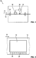
- FIG 1 a schematic, greatly simplified representation of a full-color printer 10 for printing a printing material 12 is shown. Alternatively, it can also be a color copier.
- the in Figure 1 The illustrated embodiment is the printing material 12 is a paper web transported in the direction of the arrow P1, which is printed with the aid of the color printer 10. Alternatively, sheet-shaped or sheet-shaped printing materials can also be printed.
- the printing material 12 is guided past a printing unit 16 with the aid of transport elements 14, with the aid of which ink, toner or printing ink is used to generate a multicolored print image is applied to the printing material 12.
- the multicolored print image is applied in particular in such a way that several color separations are printed one on top of the other.
- the colors of the color extracts are applied over the full area, rasterized or not, depending on the location, so that the colors are printed next to one another or in any combination on top of one another at different points.
- four color separations namely a first color separation in black, a second color separation in yellow, a third color separation in cyan and a fourth color separation in magenta are printed.
- FIG. 2 a schematic plan view of the printing material 12 is shown, the print image generated with the aid of the printing unit 16 being denoted by the reference numeral 18.
- the different colored color separations are printed on top of each other in perfect register, ie that they have a predetermined target alignment relative to one another so that the individual color separations overlap as planned and the desired colors in the individual partial areas of the print image 18 result. If the position of one color separation differs from the predetermined relative alignment to one another relative to the position of another color separation, that is to say that a so-called register error is present, it may be that a blurred print image 18 with color fringes is created.
- a plurality of control fields are printed by the printing unit 16 together with the print image 18 on at least one edge area of the printing material 12, one of which is designated by the reference symbol 20 by way of example.
- the control fields 20 are used to check the settings of the printer 10.
- at least one of the control fields 20 is used to determine the registration error between at least two color separations.
- a predetermined pattern of the control field 20, such as this in connection with the Figures 5 to 10 described in more detail is printed.
- the color value of the control field 20 is determined integrally over the entire control field and compared with a target color value of the respective control field 20 that the control field 20 should have if there is no registration error.
- the control unit 24 controls the printing unit 16 as a function of the determined control variable in such a way that when the print image 18 is generated in the future, the registration error is at least reduced by changing the alignment of the color separations with one another accordingly.
- the point in time at which the ink is ejected from the nozzles is changed.
- the print image can be shifted pixel by pixel transversely to the printing direction by assigning the nozzles used accordingly.
- the printing unit can also be moved by a motor.
- the latent image can also be shifted via the character generator.
- the control field 20 includes in particular a pattern in which all the colors of the color separations used to generate the print image 18 occur and which is designed in such a way that with its help the registration errors of all color separations used are determined relative to one another both along the transport direction and across the transport direction P1 be able.
- several control fields 20 can also be used, with the aid of which the misregistration of the individual color separations with respect to one another can be determined.
- the patterns are designed in such a way that, depending on the misregistration, different overlaps of the colors of the color separations result in other color values of the control field 20 or the control fields 20, so that the deviation of the determined color value of the control field 20 or the determined color values of the control fields 20 increases the desired color value or the desired color values of the registration errors or the registration errors can be determined.
- a three-range color measuring device or a spectral color measuring device is used as the color value sensor.
- the color value of the control field 20 is determined in a color space, in particular as a coordinate of the Lab color space.
- the determination can take place directly as a coordinate in the Lab color space or a reflection value and / or a coordinate in another color space can also be determined first, which is then converted into the coordinate of the Lab color space.
- a brightness value, a value of a red-green axis or a value of a yellow-blue axis is thus determined as the color value.
- other color spaces in which the color values are determined can also be used.
- color density measuring devices or RGB sensors can also be used as color value sensors.
- the Neugebauer model can be used, in which the color value of the colors can be determined in a raster print based on solid tones. According to the model, the visually perceived color impression depends on the spectral reflection factors of the unprinted or printed paper and on the proportion of the areas on the control field covered with the different colors of the color separations.
- R. R. P. * F. P. + R. C. * F. C. + R. M. * F. M. + R. Y * F. Y + R. K * F. K + R. CM * F. CM + R. CY * F. CY + R. CK * F. CK + R. MY * F. MY + R. MK * F. MK + R. YK * F. YK + R. CMY * F. CMY + R. CMK * F. CMK + R.
- the reflection factors R of the layers printed on top of one another can thus be calculated by multiplying the reflection factors of the individual layers. These have to be calculated by dividing the reflection factor of the full tone on paper by the reflection factor of the unprinted paper in order to obtain values that are independent of the reflection properties of the paper. This is necessary above all because the reflective properties of the paper would otherwise be taken into account several times when overprinted.
- the reflection factors of the full tones are determined in particular by printing several reference fields 26 on the printing material 12 in addition to the control field 20, with at least one reference field 26 being printed for each printing color, which has the full tone of this color, that is, completely with the respective color is printed.
- the color value is then determined for each of the reference fields 26, which then delivers the color value of the respective full tone, with the help of which the target color value for the control field 20 can be determined using the above formula according to Neugebauer, since in the predetermined pattern of the control field 20 is known which area portions of which color this pattern would ideally have if there is no misregistration.
- AEab, ⁇ E99, ⁇ E00 Different optimization levels can be used, as they are known from DIN 6174, DIN 6176 and CIE 15-2004. Appropriate differential dimensions must be used for color density measurements or measurements using RGB sensors.
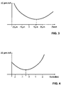
- FIG 3 a diagram for determining the registration error between at least two color separations according to a first embodiment is shown.
- a color value of the control field 20 a target value for the precisely registered printing of the control field 20
- a plurality of target values for predetermined possible registration errors are determined.
- the target values are calculated theoretically, in particular.
- the curve resulting in this way would have to have its minimum at the point zero, i.e. in the case of precisely registered printing, since at this point the deviation between the determined color value and the target color value would have to be the smallest, ideally the Should have a value of zero.
- the remaining difference is due to color variation, for example by color variations or fixation variations.
- the minimum of the determined curve is not at the point zero, but at the point at which the assumed registration error for calculating the corresponding target color value corresponds to the value of the registration error that has actually occurred is equivalent to.
- a curve is thus initially determined, in particular by interpolation, on the basis of a large number of determined desired color values and the respective deviation of the color value determined with the aid of the color measuring device 22 from these theoretical desired color values. The minimum of this curve is then determined and the registration error is determined from this.
- FIG 4 a diagram for determining the registration error according to a second embodiment is shown.
- this second embodiment only one target value is determined for the control field 20, namely the target color value that the control field 20 would have in the case of precisely registered printing.
- several control fields 20 are printed on the printing material 12, the control fields 20 each having the same pattern, the color separations being printed offset from one another by different predetermined values when this pattern is generated in the individual control fields 20.
- the color value of each of the control fields 20 is determined with the aid of the color value sensor 22.
- the deviation of this determined color value from the target color value is then calculated and, as in FIG Figure 4 shown, plotted over the respective predetermined deviation of the color separations in the respective control field 20.
- a compensation function is created from the resulting values with the help of a compensation procedure.
- an interpolation method is used.
- the resulting curve has its minimum at the point zero, that is, the deviation of the color value of that control field 20 in which the color separations are printed without offset to one another from the calculated one Target color value would be the lowest.
- the registration error can be determined by multiplying the deviation of the field of the minimum by (-1).
- the nominal color value of the control field 20 cannot be calculated from a plurality of reference fields 26, but rather can be determined via a single reference field 26 with the aid of the color value sensor 22.
- this additionally applied reference field 26 has a pattern which is designed such that it always delivers the same color value, namely the target color value, up to a predetermined limit value of the registration error, regardless of the existing registration error.
- the additionally applied reference field 26 has, in particular, the same area proportions of the respective colors as the pattern of the control field 20, whereby in contrast to the pattern of the control field 20, however, the colors, provided that the actual registration error does not exceed the preset limit value, are applied so far apart that the individual colors can overlap, but the proportions of the individual colors and the superimposed colors in the reference field 26 always remain constant despite shifts due to a misregistration. This results in the same color value regardless of the existing registration error.
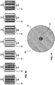
- FIG 11 Such a register-independent reference field 26 according to a first embodiment is shown.
- the differently colored segments 60, 62 are arranged mirror-symmetrically to a central axis 64 of the reference field 26, so that, regardless of the existing registration error, the differently colored segments 60, 62, viewed over the entire reference field 26, overlap each other to the same extent.
- the unprinted parts 66 of the reference field 26 also remain constant, so that the determined integral color value of the reference field 26 is independent of the registration error actually present.
- the reference field 26 is designed, in particular, in such a way that this resulting setpoint color value corresponds to the color value of the control field 20 if there is no registration error in the control field 20.
- the same colors are used for the segments 60, 62 of the reference field 26 as for the segments of the control field 20, the respective area proportions of the individual color segments and the overlaps or the unprinted areas in the reference field 26 and the precisely registered control field 20 being the same.
- a reference field 26 according to a second embodiment is shown, which also has the same color value as the target color value regardless of the registration error that occurs supplies.
- the reference field 26 has a pattern which consists of intersecting, in particular orthogonally intersecting, segments 70, 72 of different colors. With this pattern, too, the proportions of pure colors, the proportions of overlaps and the proportions of uncolored areas remain constant.
- FIG 13 a schematic representation of a plurality of reference fields 26 according to a third embodiment is shown.
- a large number of reference fields 26 are printed, the reference fields 26 each having alternating cyan-colored stripes 32, magenta-colored stripes 36 and unprinted stripes, the cyan-colored stripes 62 and the mangenta-colored stripes 36 from reference field to reference field 26 are printed with a different offset to each other and thus overlap to different extents.
- the color value of each of the reference fields 26 is determined with the aid of the color value sensor 22.
- the desired color value can now be determined in a simple manner either as one of the extreme values of the determined color values or by averaging the two extreme values determined.
- a complete overlap of the stripes 32, 36 will take place in one of the reference fields 26 and the stripes 32, 36 will be completely juxtaposed with one of the reference fields 26 so that the target color value can be determined from these values.
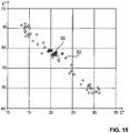
- FIG. 12 is a diagram of experimentally determined color values of a crossed reference field 26 from FIG Figure 12 and of a control field 20 with parallel stripes of the same colors as the reference field 26 with different misregistration.
- the chroma C * is plotted on the x-axis and the brightness L * is plotted on the y-axis.
- the measured values of the crossed reference field 26 are shown here by the squares 90, the measured values of the striped control field 20 by the circles 92.
- the crossed reference field 26 used in the experiment has approximately the same chroma C * and the same brightness L *, regardless of the existing registration error.
- the squares 90 are therefore close together.
- the determined measured values fluctuate significantly between two extremes, one extreme representing the complete overlapping of the different colored stripes and the other extreme representing the complete juxtaposition of the different colored stripes.
- there is a deviation ⁇ E 25 between these two extremes.
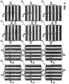
- FIG 5 a schematic representation of control fields 20 according to a first embodiment is shown.
- twelve control fields are used relative to one another to determine the registration errors of all four basic colors used in full-color printing, the corresponding registration errors being determined relative to black for each of cyan, magenta and yellow.
- Four control fields 20 are provided for each color, the pattern of two of the control fields 20 being mirror-symmetrical and the pattern of the other two control fields 20 relative to the first two control fields 20 are arranged rotated by 90 °.
- control fields 20 shown each show the ideal pattern when there is no registration error.
- the first control field i.e. the control field in Figure 5 is shown at the top left, describes what would happen if a misregistration occurred.
- both the color components of the black-colored area and the cyan remain colored areas as well as the unprinted area in the first control field remain unchanged, provided that the misregistration does not exceed the width of the stripes 30 to 34.
- the mirror-symmetrical arrangement of the pattern in the second control field i.e. the control field in the first row, the second from the left, ensures that a registration error in the second direction opposite to the first direction, i.e. a registration error to the right, can be determined with this control field .
- a registration error that is orthogonal to the first or orthogonal to the second direction, i.e. a registration error in the Figure 5 can be determined upwards or downwards.
- control fields are provided for the corresponding determination of the registration errors of the other two colors, i.e. for magenta and yellow relative to black.
- these further eight control fields each have the same pattern, mirrored and rotated accordingly.
- FIG 6 a schematic representation of the control fields 20 according to the second embodiment of the invention is shown.
- only eight control fields 20 are necessary to determine the registration errors of all four colors relative to one another.
- the strips 34 which are not printed in the first embodiment are also used in each case printed with another color.
- each pattern thus comprises alternating black stripes 30, cyan-colored stripes 32 and either magenta-colored stripes 36 or yellow stripes 38.
- the overlapping of the individual stripes 30, 32, 36, 38 different colors and thus also different resulting color values of the control fields 20.
- a misregistration of the cyan color separation to the left occurs in the control field in the upper left corner, the proportion of the black and magenta colored areas remains the same, whereby the proportion of cyan-colored areas decreases and the proportion of unprinted areas increases.
- the cyan-colored separation is shifted to the right, the black-colored areas remain the same, whereas the proportion of cyan-colored areas and magenta-colored areas decreases and the proportion of unprinted areas and blue areas increases.
- Figure 7 a schematic representation of four control fields 20 according to a third embodiment is shown, in this embodiment only the registration error between black and cyan is determined.
- the Figures 7a and 7b show two control fields 20 if there is no registration error.
- the control fields 20 each have alternating black and cyan-colored stripes 30, 32, the pattern of the control field 20 being detected Figure 7b relative to the pattern of the control field 20 of Figure 7a rotated by 90 °.
- Figure 7c shows the resulting pattern when following control field 20 Figure 7a the cyan color separation is shifted upwards. Shows accordingly Figure 7d the control field 20 after Figure 7b if there is a registration error in which the cyan color separation is shifted to the left relative to the black color separation.
- the size of the misregistration corresponds to the Figures 7c and 7d the width of the white fields.
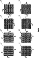
- Figure 8 two control fields 20 are shown according to a fourth embodiment, wherein Figure 8a the control field 20 in the case of a precisely registered print and Figure 8b the control field 20 shows in the presence of a misregistration.
- the control panel 20 after Figure 8a has a pattern in which completely black colored stripes and stripes, each alternating with yellow and black squares, are arranged.
- Figure 8b the resulting pattern is shown that results from a misregistration in which the yellow color separation is arranged offset downwards relative to the black color separation.
- the yellow part decreases, whereas the unprinted part, i.e. the white part, increases.
- the black part remains unchanged. A different color value results accordingly.
- Figure 9 shows two control fields 20 according to a fifth embodiment, wherein in Figure 9a again the exact register print and in Figure 9b the resulting pattern is shown in the event of a misregistration in which the yellow color separation is arranged offset downwards relative to the other three color separations.
- the control panel 20 after Figure 9a has a checkerboard-like pattern, the respective lines alternating with yellow and magenta-colored squares or black and cyan-colored squares.
- the use of such a checkerboard-like pattern has the advantage that fewer control fields are necessary to determine all registration errors of all color separations relative to one another, since depending on the direction in which which color separation is shifted relative to the others, different colors are shifted due to the overlapping of the individual ones Color separations result and thus a different color value results.
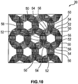
- FIG 10 a schematic representation of a control field 20 according to a sixth embodiment is shown, with this sixth embodiment of the control field 20 having a pattern in which the four printing inks used are arranged in such a way that with the help of this only one control field 20 all registration errors in all directions can be determined leave.
- the colors are arranged in such a way that, depending on the direction in which which color separation is offset relative to which other color separation, a different color value of the control field 20 results.
- the pattern according to Figure 10 has a plurality of ring-shaped dodecagons, each dodecagon in turn having six triangles 50 colored black, the tips of which are directed towards the center of the dodecagon.
- the triangles 50 are, in particular, equilateral triangles and each have the same angular spacing from one another. Between the black triangles 50 two colored stripes 52 to 56 are arranged, with a yellow stripe 52 and a cyan-colored stripe 54 and a yellow stripe 52 and magenta-colored stripes 54 alternating between two adjacent black triangles 50 a magenta-colored stripe 56 and a cyan-colored stripe 54 are arranged.
- control fields 20 In addition, a large number of other possible patterns for the control fields 20 are conceivable. Depending on the pattern used, the number of necessary control fields 20 varies in order to be able to determine all conceivable registration errors.
- control fields 20 can also be used, in which the patterns are selected in such a way that they each have the same color components of different colors, but different numbers of different widths of stripes. If strips with a large distance from one another, ie that there is a large unprinted space between them, are used, the color composition of the control field 20 does not change even if a minor misregistration occurs, so that the color value remains unchanged. In the case of control fields 20 with a relatively small spacing, on the other hand, an overlay of the stripes occurs even with a small misregistration, so that the color value of the control field 20 changes. Correspondingly, the present registration error can in turn be determined via the color values.
- the registration errors can be determined with high accuracy exclusively via the color values, even if there is only a small registration error.
- This has the advantage that no additional sensors are necessary. In particular, no sensors are necessary that deliver high-resolution images of the control fields 20 in which the deviation is then measured.
- the color value sensors 22 are generally already present in color printers 10 anyway. Furthermore, such color value sensors 22 are inexpensive compared to high-resolution sensors and require only a small amount of installation space. In particular, it is not necessary to use several sensors on the one hand for color measurement and on the other hand for register control. In particular, this also results in a high measuring speed.
- control fields 20 are compatible with the control fields used anyway, since they are of the same size and can also be printed on at the edge area.
- the stripe width is selected in particular such that the maximum registration error that occurs is less than this stripe width. If the maximum registration error that occurs is larger than the strip width, the registration error cannot be determined precisely. In this case, strips with a larger width can be used.
- a pattern for the control field 20 with wide stripes can first be used and the stripe width can be increasingly reduced during operation. It is also possible to change the patterns used in the control field 20 or the number of control fields 20 used in the printing operation as a function of the registration errors that occur. In particular, initially only one control field 20 with all the colors used is used and only when Registration errors or the exceeding of preset limit values of the registration error, additional control fields 20 are printed, with the help of which the direction of the registration error is determined and / or with the help of which a more precise determination of the registration error is possible.
- control fields 20 and reference fields 26 can only be printed on until there is no more registration error or this is within tolerable limits.
- the toner or the printing ink to be applied only simply structured monitoring fields 80 are then initially printed instead of control fields 20 and reference fields 26.
- Such a monitoring field is in Figure 14 shown.
- the monitoring field 80 comprises a large circle 82 of a first color and a much smaller circle 84 of a second color. If there is no registration error between the color separations of these two colors, the centers of the two circles 82, 84 coincide.
- the small circle moves relative to the large circle, the small circle 84 remaining in the large circle 82 until the registration error is greater than the difference between the two radii of the two circles 82, 84.
- the color value of this monitoring field 80 does not change.
- the radii are chosen such that, as long as this is the case, the misregistration is within a tolerable extent. Only when the registration error exceeds the tolerable level and thus the color value of the monitoring field 80 changes, instead of the monitoring field 80, control fields 20 and reference fields are printed again and the registration error is corrected according to the method described above.
- the measuring range of the color sensor 22 is selected in particular in such a way that it is smaller than the size of the control fields 20 or the reference fields 26 or the monitoring field 80, so that even if there are registration errors it is ensured that the area covered by the measuring range of the color sensor 22 Area is independent of the registration error and thus the error has no influence on the measurement itself.
- the width of the measurement area is in particular a multiple of the width of the strips or segments of the control fields 20.
Claims (9)
- Procédé pour commander une imprimante couleur ou un photocopieur couleur,selon lequel au moins une sélection de couleur d'une première couleur et une sélection de couleur d'une deuxième couleur sont appliquées sur un support d'impression (12) à imprimer pour produire une image imprimée (18),au moins un champ de contrôle (20) est imprimé sur le même support d'impression (12) à l'aide d'une unité d'impression (16), dans lequel le champ de contrôle (20) présente un motif prédéfini, qui comprend au moins la première couleur et la deuxième couleur et qui est réalisé de telle sorte que la valeur de couleur du champ de contrôle varie en fonction de l'erreur de repérage entre la première et la deuxième sélection de couleur,la valeur de couleur du champ de contrôle (20) est mesurée intégralement sur l'ensemble du champ de contrôle (20) à l'aide d'un capteur de valeur de couleur (22) dans un espace de couleur,caractérisé en ce queau moins un champ de référence (26), dont le motif est prédéfini de telle sorte qu'il présente la même valeur de couleur indépendamment de l'erreur de repérage, est imprimé sur le même support d'impression (12),la valeur de couleur du champ de référence (26) est déterminée à l'aide du capteur de valeur de couleur (22),une valeur de couleur théorique est déterminée en fonction de la valeur de couleur du champ de référence (26),un écart entre la valeur de couleur mesurée du champ de contrôle (20) et la valeur de couleur théorique est déterminé en tant que distance euclidienne dans l'espace de couleur, dans lequel l'écart correspond à un déplacement local des sélections de couleur,ce qui a pour effet que l'erreur de repérage est déterminée, etselon lequel au moins un signal de commande pour réduire le déplacement local des sélections de couleur est produit en fonction de l'écart déterminé.
- Procédé selon la revendication 1,
caractérisé en ce que le champ de contrôle (20) imprimé est un premier champ de contrôle, qu'au moins un autre champ de contrôle (20) est imprimé sur le support d'impression (12), dans lequel pour l'autre champ de contrôle (20) les zones encrées avec la première couleur sont disposées comme pour le motif du premier champ de contrôle (20) et les zones encrées avec la deuxième couleur sont déplacées par rapport aux zones de la première couleur selon une valeur préréglée dans une direction préréglée, que la valeur de couleur de l'autre champ de contrôle (20) est déterminée à l'aide du capteur de valeur de couleur (22), qu'un écart entre la valeur de couleur théorique et la valeur de couleur déterminée de l'autre champ de contrôle (20) est déterminé, et que le signal de commande est défini en fonction de l'écart entre la valeur de couleur déterminée du premier champ de contrôle (20) et la valeur de couleur théorique ainsi que de l'écart entre la valeur de couleur déterminée de l'autre champ de contrôle (20) et la valeur de couleur théorique. - Procédé selon l'une quelconque des revendications précédentes, caractérisé en ce que le motif du champ de contrôle (20) présente respectivement en alternance une bande (30) de la première couleur, une bande (32) de la deuxième couleur et une bande (34) non imprimée.
- Procédé selon la revendication 3, caractérisé en ce que le champ de contrôle (20) est un premier champ de contrôle, qu'au moins un deuxième champ de contrôle (20) est imprimé, dont le motif est en symétrie spéculaire par rapport au motif du premier champ de contrôle (20), qu'une valeur de couleur du deuxième champ de contrôle (20) est mesurée à l'aide du capteur de valeur de couleur (22), qu'un écart de la valeur de couleur du deuxième champ de contrôle (20) par rapport à la valeur de couleur théorique est déterminé, et que le signal de commande est défini en fonction de l'écart de la valeur de couleur déterminée du premier champ de contrôle (20) et de l'écart déterminé du deuxième champ de contrôle (20).
- Procédé selon l'une quelconque des revendications précédentes, caractérisé en ce qu'une sélection de couleur d'une troisième couleur pour produire l'image imprimée (18) est appliquée sur le support d'impression (12) à imprimer, qu'au moins un troisième champ de contrôle (20) est imprimé sur le support d'impression (12) à l'aide de l'unité d'impression (16), dans lequel le troisième champ de contrôle (20) présente un motif prédéfini, qui comprend au moins la première couleur et la troisième couleur, qu'au moins une valeur de couleur du troisième champ de contrôle (20) est mesurée à l'aide du capteur de valeur de couleur (22), qu'un écart entre la valeur de couleur mesurée du troisième champ de contrôle (20) et une valeur de couleur théorique du troisième champ de contrôle (20) est déterminé, et qu'en fonction de cet écart déterminé de la valeur de couleur déterminée du troisième champ de contrôle (20) par rapport à la valeur de couleur théorique du troisième champ de contrôle (20), au moins un signal de commande d'une commande pour réduire l'erreur de repérage entre la sélection de couleur de la première couleur et la sélection de couleur de la troisième couleur est défini.
- Procédé selon l'une quelconque des revendications précédentes, caractérisé en ce qu'une pluralité de champs de contrôle (20) sont imprimés, dans lequel pour chaque champ de contrôle (20) les zones des deux couleurs sont déplacées l'une par rapport à l'autre selon une autre valeur prédéfinie, que la valeur de couleur de chaque champ de contrôle (20) est déterminée à l'aide du capteur de valeur de couleur (22) et respectivement l'écart par rapport à la valeur théorique est calculé, que le champ de contrôle (20) avec l'écart le plus petit est sélectionné, que la valeur de laquelle les zones des deux couleurs sont déplacées l'une par rapport à l'autre pour ce champ de contrôle (20) sélectionné est multipliée par moins un et est définie en tant que valeur pour l'erreur de repérage effective, et que la grandeur de commande est définie en fonction de l'erreur de repérage effective.
- Procédé selon l'une quelconque des revendications précédentes, caractérisé en ce qu'une sélection de couleur d'une troisième couleur pour produire l'image imprimée (18) est appliquée sur un support d'impression (12) à imprimer, que le motif du champ de contrôle (20) comprend la troisième couleur, et qu'en fonction de l'écart déterminé, une grandeur de commande d'une commande pour la réduction de l'erreur de repérage entre la sélection de couleur de la première couleur et la sélection de couleur de la deuxième couleur et au moins une grandeur de commande pour la commande pour la réduction de l'erreur de repérage entre la sélection de couleur de la première couleur et la sélection de couleur de la troisième couleur sont définies.
- Procédé selon l'une quelconque des revendications précédentes, caractérisé en ce que la valeur de couleur du champ de référence (26) mesurée à l'aide du capteur de valeur de couleur (22) est utilisée comme valeur de couleur théorique.
- Procédé selon l'une quelconque des revendications 1 à 7, caractérisé en ce que la valeur de couleur théorique est calculée sur la base de la valeur de couleur du champ de référence (26) mesurée à l'aide du capteur de valeur de couleur (22).
Applications Claiming Priority (2)
| Application Number | Priority Date | Filing Date | Title |
|---|---|---|---|
| DE102012104584A DE102012104584A1 (de) | 2012-05-29 | 2012-05-29 | Verfahren zum Steuern eines Farbdruckers oder Farbkopierers |
| PCT/EP2013/001591 WO2013178360A1 (fr) | 2012-05-29 | 2013-05-29 | Procédé de commande d'une imprimante couleur ou d'un copieur couleur |
Publications (2)
| Publication Number | Publication Date |
|---|---|
| EP2855154A1 EP2855154A1 (fr) | 2015-04-08 |
| EP2855154B1 true EP2855154B1 (fr) | 2021-12-08 |
Family
ID=48703395
Family Applications (1)
| Application Number | Title | Priority Date | Filing Date |
|---|---|---|---|
| EP13732353.1A Active EP2855154B1 (fr) | 2012-05-29 | 2013-05-29 | Procédé de commande d'une imprimante couleur ou d'un copieur couleur |
Country Status (5)
| Country | Link |
|---|---|
| US (1) | US9462162B2 (fr) |
| EP (1) | EP2855154B1 (fr) |
| JP (1) | JP6058127B2 (fr) |
| DE (1) | DE102012104584A1 (fr) |
| WO (1) | WO2013178360A1 (fr) |
Families Citing this family (11)
| Publication number | Priority date | Publication date | Assignee | Title |
|---|---|---|---|---|
| EP3172052B1 (fr) * | 2014-07-22 | 2019-08-28 | The Coca-Cola Company | Systèmes et procédés pour surveiller l'orientation de surimpression |
| DE102015219245B3 (de) * | 2015-10-06 | 2016-11-17 | Heidelberger Druckmaschinen Ag | Verfahren zur effizienten Papierdehnungskompensation |
| CN105346220A (zh) * | 2015-12-15 | 2016-02-24 | 河南润嘉新材料科技有限公司 | 一种蓝光定位跟踪套印系统 |
| US9699328B1 (en) * | 2016-04-04 | 2017-07-04 | Eastman Kodak Company | Registration correction for periodic ink coverage patterns |
| DE102016107772B3 (de) * | 2016-04-27 | 2017-05-11 | Océ Holding B.V. | Verfahren zum Übertragen eines Tonerbildes von einem Transferelement auf einen Aufzeichnungsträger |
| DE102016216017A1 (de) | 2016-08-25 | 2018-03-01 | Roth + Weber Gmbh | Farbdruckwerk mit einer Steuervorrichtung und jeweils einer Druckstation für jede Farbe |
| CN106739485B (zh) * | 2016-12-13 | 2019-01-04 | 北京印刷学院 | 一种印刷机纵向套准在线检测与故障诊断方法及装置 |
| CN106897996A (zh) * | 2017-02-04 | 2017-06-27 | 同济大学 | 基于机器视觉的套印误差检测方法 |
| WO2018199882A1 (fr) | 2017-04-24 | 2018-11-01 | Hewlett-Packard Development Company, L.P. | Transformation d'un vecteur d'espace couleur en un vecteur de couverture de zone primaire de neugebauer |
| US20210023867A1 (en) * | 2018-04-13 | 2021-01-28 | Hewlett-Packard Development Company, L.P. | Imaging medium |
| EP3815911A1 (fr) * | 2019-10-31 | 2021-05-05 | Canon Production Printing Holding B.V. | Procédé d'impression sur un support d'un type de milieu donné |
Citations (1)
| Publication number | Priority date | Publication date | Assignee | Title |
|---|---|---|---|---|
| US20030210412A1 (en) * | 2002-03-25 | 2003-11-13 | Hitoshi Ishibashi | Misalignment correction pattern formation method, misalignment correction method, and color image formation apparatus |
Family Cites Families (34)
| Publication number | Priority date | Publication date | Assignee | Title |
|---|---|---|---|---|
| JPS58118261A (ja) | 1981-12-30 | 1983-07-14 | コルモ−ゲン・テクノロジイズ・コ−ポレイシヨン | 色整合を認識し、かつこれを維持するための方法及び装置 |
| US4546700A (en) | 1981-12-30 | 1985-10-15 | Kollmorgen Technologies Corporation | Method and apparatus for sensing and maintaining color registration |
| DE4335350A1 (de) * | 1993-10-16 | 1995-04-20 | Heidelberger Druckmasch Ag | Verfahren und Vorrichtung zur Ermittlung von Passerabweichungen bei mehrfarbigen, in einer Druckmaschine erstellten Druckprodukten |
| JP3324307B2 (ja) * | 1994-12-02 | 2002-09-17 | 株式会社日立製作所 | カラー画像形成装置の色補正方法及びカラー画像形成装置 |
| US5751450A (en) * | 1996-05-22 | 1998-05-12 | Medar, Inc. | Method and system for measuring color difference |
| DE19638967C2 (de) * | 1996-09-23 | 1998-12-17 | Empa | Messfeldgruppe und Verfahren zur Erfassung von optisch drucktechnischen Größen im Mehrfarben-Auflagendruck |
| ATE210555T1 (de) | 1996-09-23 | 2001-12-15 | Wifag Maschf | Messfeldblock und verfahren zur erfassung von qualitätsdaten im mehrfarben-auflagendruck |
| DE19639014C2 (de) * | 1996-09-23 | 1998-12-03 | Wifag Maschf | Messfeldgruppe und Verfahren zur Erfassung von optisch drucktechnischen Größen im Mehrfarben-Auflagendruck |
| DE19701967C2 (de) | 1997-01-22 | 1999-08-05 | Andreas Paul | Verfahren zur Bestimmung der farblichen Erscheinung sowie entsprechende Vorrichtung |
| US6198549B1 (en) * | 1997-07-31 | 2001-03-06 | International Business Machines Corporation | System, method, program, and print pattern for performing registration calibration for printers by measuring density |
| DE19738992A1 (de) | 1997-09-05 | 1999-03-11 | Empa | Messfeldblock und Verfahren zur Erfassung von Qualidätsdaten im Mehrfarben-Auflagendruck |
| EP0909646B1 (fr) * | 1997-10-14 | 2002-03-27 | Xeikon Nv | Procédé pour commander le régistre d'images imprimées dans une imprimante |
| JP2002148890A (ja) * | 2000-08-29 | 2002-05-22 | Casio Electronics Co Ltd | カラー画像形成位置調整装置 |
| DE10131957A1 (de) | 2001-07-02 | 2003-01-16 | Nexpress Solutions Llc | Verfahren und Vorrichtung zum Erfassen und Korrigieren von Farbabweichungen beim Mehrfarbdruck |
| DE10204681A1 (de) | 2002-02-06 | 2003-08-07 | Gerd Laubmann | Markierung zur Erfassung des Registerfehlers oder Passerfehlers im Mehrfarbendruck |
| JP2003341016A (ja) * | 2002-05-24 | 2003-12-03 | Dainippon Screen Mfg Co Ltd | 検出マーク、見当ずれ量測定装置、印刷装置、見当ずれ量測定方法、印刷方法およびプログラム |
| DE10244437B4 (de) | 2002-09-24 | 2009-09-17 | Maschinenfabrik Wifag | Verfahren zur Bestimmung der Position und Form von Marken auf einer bedruckten Papierbahn |
| JP4265907B2 (ja) * | 2002-12-02 | 2009-05-20 | 株式会社リコー | 画像形成装置及び画像形成の位置ずれ量検出方法 |
| US7184700B2 (en) | 2003-08-18 | 2007-02-27 | Heidelberger Druckmaschinen Ag | Method of determining color register and/or register errors in a printing machine |
| JP4553344B2 (ja) | 2003-09-04 | 2010-09-29 | キヤノン株式会社 | 記録装置 |
| JP2005091005A (ja) * | 2003-09-12 | 2005-04-07 | Dainippon Printing Co Ltd | 色評価装置 |
| US20050157317A1 (en) * | 2004-01-16 | 2005-07-21 | Xerox Corporation | Systems and methods for spectrophotometric assessment of color misregistration in an image forming system |
| DE102004021597B4 (de) | 2004-05-03 | 2017-04-13 | Heidelberger Druckmaschinen Ag | Registermarke |
| JP4885554B2 (ja) * | 2006-02-13 | 2012-02-29 | 京セラミタ株式会社 | 色ずれ検出用マーク、色ずれ検出方法及びカラー画像形成装置 |
| US8270049B2 (en) * | 2006-08-01 | 2012-09-18 | Xerox Corporation | System and method for high resolution characterization of spatial variance of color separation misregistration |
| DE102006036587A1 (de) | 2006-08-04 | 2008-02-07 | Man Roland Druckmaschinen Ag | Messelement zur Messung eines Farbregisters sowie Verfahren zur Farbregisterregelung bzw. Farbregistermessung |
| DE102007041393B4 (de) * | 2007-08-31 | 2010-12-16 | Eastman Kodak Co. | Verfahren zum Kalibrieren einer Mehrfarben-Druckmaschine |
| DE102008025419A1 (de) | 2008-05-27 | 2009-12-03 | Manroland Ag | Verfahren zur Farbregistermessung an einer Druckmaschine |
| JP2009296545A (ja) * | 2008-06-09 | 2009-12-17 | Canon Inc | 画像処理装置およびその方法 |
| DE102009035006B4 (de) | 2008-09-08 | 2019-06-06 | Heidelberger Druckmaschinen Ag | Intensitätsoptimierte Kontrollmarkenmessung |
| US8204416B2 (en) * | 2008-12-02 | 2012-06-19 | Xerox Corporation | Method and apparatus for measuring color-to-color registration |
| DE102010036249A1 (de) | 2009-10-01 | 2011-04-07 | Heidelberger Druckmaschinen Ag | Verfahren und Vorrichtung zur Ermittlung von Passerabweichungen mittels Rekursionsanalyse |
| US8355189B2 (en) * | 2010-05-14 | 2013-01-15 | Hewlett-Packard Development Company, L.P. | Reducing the visibility of color changes caused by color plane registration variations in halftone color printing |
| US9075374B2 (en) * | 2010-07-20 | 2015-07-07 | Hewlett-Packard Indigo B.V. | Method and apparatus for assessing the operation of a color printing system |
-
2012
- 2012-05-29 DE DE102012104584A patent/DE102012104584A1/de not_active Withdrawn
-
2013
- 2013-05-29 WO PCT/EP2013/001591 patent/WO2013178360A1/fr active Application Filing
- 2013-05-29 EP EP13732353.1A patent/EP2855154B1/fr active Active
- 2013-05-29 US US14/400,755 patent/US9462162B2/en active Active
- 2013-05-29 JP JP2015514379A patent/JP6058127B2/ja active Active
Patent Citations (1)
| Publication number | Priority date | Publication date | Assignee | Title |
|---|---|---|---|---|
| US20030210412A1 (en) * | 2002-03-25 | 2003-11-13 | Hitoshi Ishibashi | Misalignment correction pattern formation method, misalignment correction method, and color image formation apparatus |
Also Published As
| Publication number | Publication date |
|---|---|
| US20150156376A1 (en) | 2015-06-04 |
| US9462162B2 (en) | 2016-10-04 |
| JP2015523238A (ja) | 2015-08-13 |
| JP6058127B2 (ja) | 2017-01-11 |
| DE102012104584A1 (de) | 2013-12-05 |
| EP2855154A1 (fr) | 2015-04-08 |
| WO2013178360A1 (fr) | 2013-12-05 |
Similar Documents
| Publication | Publication Date | Title |
|---|---|---|
| EP2855154B1 (fr) | Procédé de commande d'une imprimante couleur ou d'un copieur couleur | |
| EP0255586B1 (fr) | Procédé et dispositif pour influencer l'encrage d'une surface encrée dans une machine à imprimer | |
| EP2008818B1 (fr) | Bandes de contrôle de pression améliorées destinées à la mesure de la couleur sur une matière d'impression | |
| DE10359322B4 (de) | Verfahren und Vorrichtung zur Korrektur von nicht angepassten Druckdaten anhand eines farbmetrisch vermessenen Referenzbogens | |
| DE102004003612B4 (de) | Verfahren und Auswertung eines Bildes von einem vorbestimmten Ausschnitt eines Druckerzeugnisses | |
| DE19703129B4 (de) | Verfahren zur Bewertung der Qualität eines im Mehrfarbendruck auf einem Bedruckstoff erzeugten Druckbildes | |
| DE19749066A1 (de) | Verfahren zur Regelung des Farbauftrages bei einer Druckmaschine | |
| DE102010036249A1 (de) | Verfahren und Vorrichtung zur Ermittlung von Passerabweichungen mittels Rekursionsanalyse | |
| EP0836942B1 (fr) | Bloc de mesure et procédé d'acquisition des données de qualité dans des machines d'impression multicoloré | |
| DE102012004482A1 (de) | Nutzenfarboptimierung | |
| DE69909843T2 (de) | Automatische register- und längeeinstellung | |
| EP1199168A1 (fr) | Procédure et dispositif de détection d'une déviation de registre dans l'impression polychrome ainsi que de contrôle du repérage et des marques de registre | |
| EP2049336B1 (fr) | Élément de mesure pour mesurer un registre de couleur et procédé de réglage du registre de couleurs et/ou de mesure du registre de couleurs | |
| DE102019113267B4 (de) | Verfahren zum Betreiben einer Tintenstrahldruckmaschine mit zumindest einer Modifikationsfunktion | |
| DE102010051952B4 (de) | Analyse Farbauszüge | |
| EP0590282B1 (fr) | Barres de contrÔle pour commander et surveiller le processus d'impression | |
| DE3942254C2 (fr) | ||
| DE102022109630A1 (de) | Verfahren zum Betreiben einer Tintenstrahldruckmaschine unter Verwendung zumindest eines künstlichen neuronalen Netzes | |
| DE3248795C2 (de) | Verfahren und Vorrichtung zum Bestimmen und Aufrechterhalten des Passers bei Farbdruckmaschinen | |
| DE19638967C2 (de) | Messfeldgruppe und Verfahren zur Erfassung von optisch drucktechnischen Größen im Mehrfarben-Auflagendruck | |
| DE19917773A1 (de) | Kontrollelement zum Bestimmen von Passerabweichungen eines auf einem Bedruckstoff aus mehreren Teilfarben bestehenden Druckbildes | |
| DE19639014C2 (de) | Messfeldgruppe und Verfahren zur Erfassung von optisch drucktechnischen Größen im Mehrfarben-Auflagendruck | |
| EP0649743B1 (fr) | Procédé pour contrÔler l'apport de couleur dans une presse fonctionnant suivant le procédé de similigravure | |
| CH693533A5 (de) | Messfeldblock und Verfahren zur Erfassung von Qualitotsdaten im Mehrfarben-Auflagendruck. | |
| WO2010000739A1 (fr) | Procédé de détermination de la largeur de caractères composés de points d'impression dans une machine à imprimer ou à copier |
Legal Events
| Date | Code | Title | Description |
|---|---|---|---|
| PUAI | Public reference made under article 153(3) epc to a published international application that has entered the european phase |
Free format text: ORIGINAL CODE: 0009012 |
|
| 17P | Request for examination filed |
Effective date: 20140703 |
|
| AK | Designated contracting states |
Kind code of ref document: A1 Designated state(s): AL AT BE BG CH CY CZ DE DK EE ES FI FR GB GR HR HU IE IS IT LI LT LU LV MC MK MT NL NO PL PT RO RS SE SI SK SM TR |
|
| AX | Request for extension of the european patent |
Extension state: BA ME |
|
| DAX | Request for extension of the european patent (deleted) | ||
| STAA | Information on the status of an ep patent application or granted ep patent |
Free format text: STATUS: EXAMINATION IS IN PROGRESS |
|
| 17Q | First examination report despatched |
Effective date: 20180810 |
|
| STAA | Information on the status of an ep patent application or granted ep patent |
Free format text: STATUS: EXAMINATION IS IN PROGRESS |
|
| RAP1 | Party data changed (applicant data changed or rights of an application transferred) |
Owner name: CANON PRODUCTION PRINTING GERMANY GMBH & CO. KG |
|
| GRAP | Despatch of communication of intention to grant a patent |
Free format text: ORIGINAL CODE: EPIDOSNIGR1 |
|
| STAA | Information on the status of an ep patent application or granted ep patent |
Free format text: STATUS: GRANT OF PATENT IS INTENDED |
|
| RIC1 | Information provided on ipc code assigned before grant |
Ipc: B41F 33/00 20060101AFI20210610BHEP Ipc: G03G 15/00 20060101ALI20210610BHEP |
|
| INTG | Intention to grant announced |
Effective date: 20210705 |
|
| GRAS | Grant fee paid |
Free format text: ORIGINAL CODE: EPIDOSNIGR3 |
|
| GRAA | (expected) grant |
Free format text: ORIGINAL CODE: 0009210 |
|
| STAA | Information on the status of an ep patent application or granted ep patent |
Free format text: STATUS: THE PATENT HAS BEEN GRANTED |
|
| AK | Designated contracting states |
Kind code of ref document: B1 Designated state(s): AL AT BE BG CH CY CZ DE DK EE ES FI FR GB GR HR HU IE IS IT LI LT LU LV MC MK MT NL NO PL PT RO RS SE SI SK SM TR |
|
| REG | Reference to a national code |
Ref country code: GB Ref legal event code: FG4D Free format text: NOT ENGLISH |
|
| REG | Reference to a national code |
Ref country code: AT Ref legal event code: REF Ref document number: 1453476 Country of ref document: AT Kind code of ref document: T Effective date: 20211215 Ref country code: CH Ref legal event code: EP |
|
| REG | Reference to a national code |
Ref country code: DE Ref legal event code: R096 Ref document number: 502013016009 Country of ref document: DE |
|
| REG | Reference to a national code |
Ref country code: IE Ref legal event code: FG4D Free format text: LANGUAGE OF EP DOCUMENT: GERMAN |
|
| REG | Reference to a national code |
Ref country code: LT Ref legal event code: MG9D |
|
| REG | Reference to a national code |
Ref country code: NL Ref legal event code: MP Effective date: 20211208 |
|
| PG25 | Lapsed in a contracting state [announced via postgrant information from national office to epo] |
Ref country code: RS Free format text: LAPSE BECAUSE OF FAILURE TO SUBMIT A TRANSLATION OF THE DESCRIPTION OR TO PAY THE FEE WITHIN THE PRESCRIBED TIME-LIMIT Effective date: 20211208 Ref country code: LT Free format text: LAPSE BECAUSE OF FAILURE TO SUBMIT A TRANSLATION OF THE DESCRIPTION OR TO PAY THE FEE WITHIN THE PRESCRIBED TIME-LIMIT Effective date: 20211208 Ref country code: FI Free format text: LAPSE BECAUSE OF FAILURE TO SUBMIT A TRANSLATION OF THE DESCRIPTION OR TO PAY THE FEE WITHIN THE PRESCRIBED TIME-LIMIT Effective date: 20211208 Ref country code: BG Free format text: LAPSE BECAUSE OF FAILURE TO SUBMIT A TRANSLATION OF THE DESCRIPTION OR TO PAY THE FEE WITHIN THE PRESCRIBED TIME-LIMIT Effective date: 20220308 |
|
| PG25 | Lapsed in a contracting state [announced via postgrant information from national office to epo] |
Ref country code: SE Free format text: LAPSE BECAUSE OF FAILURE TO SUBMIT A TRANSLATION OF THE DESCRIPTION OR TO PAY THE FEE WITHIN THE PRESCRIBED TIME-LIMIT Effective date: 20211208 Ref country code: NO Free format text: LAPSE BECAUSE OF FAILURE TO SUBMIT A TRANSLATION OF THE DESCRIPTION OR TO PAY THE FEE WITHIN THE PRESCRIBED TIME-LIMIT Effective date: 20220308 Ref country code: LV Free format text: LAPSE BECAUSE OF FAILURE TO SUBMIT A TRANSLATION OF THE DESCRIPTION OR TO PAY THE FEE WITHIN THE PRESCRIBED TIME-LIMIT Effective date: 20211208 Ref country code: HR Free format text: LAPSE BECAUSE OF FAILURE TO SUBMIT A TRANSLATION OF THE DESCRIPTION OR TO PAY THE FEE WITHIN THE PRESCRIBED TIME-LIMIT Effective date: 20211208 Ref country code: GR Free format text: LAPSE BECAUSE OF FAILURE TO SUBMIT A TRANSLATION OF THE DESCRIPTION OR TO PAY THE FEE WITHIN THE PRESCRIBED TIME-LIMIT Effective date: 20220309 Ref country code: ES Free format text: LAPSE BECAUSE OF FAILURE TO SUBMIT A TRANSLATION OF THE DESCRIPTION OR TO PAY THE FEE WITHIN THE PRESCRIBED TIME-LIMIT Effective date: 20211208 |
|
| PG25 | Lapsed in a contracting state [announced via postgrant information from national office to epo] |
Ref country code: NL Free format text: LAPSE BECAUSE OF FAILURE TO SUBMIT A TRANSLATION OF THE DESCRIPTION OR TO PAY THE FEE WITHIN THE PRESCRIBED TIME-LIMIT Effective date: 20211208 |
|
| PG25 | Lapsed in a contracting state [announced via postgrant information from national office to epo] |
Ref country code: SM Free format text: LAPSE BECAUSE OF FAILURE TO SUBMIT A TRANSLATION OF THE DESCRIPTION OR TO PAY THE FEE WITHIN THE PRESCRIBED TIME-LIMIT Effective date: 20211208 Ref country code: SK Free format text: LAPSE BECAUSE OF FAILURE TO SUBMIT A TRANSLATION OF THE DESCRIPTION OR TO PAY THE FEE WITHIN THE PRESCRIBED TIME-LIMIT Effective date: 20211208 Ref country code: RO Free format text: LAPSE BECAUSE OF FAILURE TO SUBMIT A TRANSLATION OF THE DESCRIPTION OR TO PAY THE FEE WITHIN THE PRESCRIBED TIME-LIMIT Effective date: 20211208 Ref country code: PT Free format text: LAPSE BECAUSE OF FAILURE TO SUBMIT A TRANSLATION OF THE DESCRIPTION OR TO PAY THE FEE WITHIN THE PRESCRIBED TIME-LIMIT Effective date: 20220408 Ref country code: EE Free format text: LAPSE BECAUSE OF FAILURE TO SUBMIT A TRANSLATION OF THE DESCRIPTION OR TO PAY THE FEE WITHIN THE PRESCRIBED TIME-LIMIT Effective date: 20211208 Ref country code: CZ Free format text: LAPSE BECAUSE OF FAILURE TO SUBMIT A TRANSLATION OF THE DESCRIPTION OR TO PAY THE FEE WITHIN THE PRESCRIBED TIME-LIMIT Effective date: 20211208 |
|
| PG25 | Lapsed in a contracting state [announced via postgrant information from national office to epo] |
Ref country code: PL Free format text: LAPSE BECAUSE OF FAILURE TO SUBMIT A TRANSLATION OF THE DESCRIPTION OR TO PAY THE FEE WITHIN THE PRESCRIBED TIME-LIMIT Effective date: 20211208 |
|
| REG | Reference to a national code |
Ref country code: DE Ref legal event code: R097 Ref document number: 502013016009 Country of ref document: DE |
|
| PG25 | Lapsed in a contracting state [announced via postgrant information from national office to epo] |
Ref country code: IS Free format text: LAPSE BECAUSE OF FAILURE TO SUBMIT A TRANSLATION OF THE DESCRIPTION OR TO PAY THE FEE WITHIN THE PRESCRIBED TIME-LIMIT Effective date: 20220408 |
|
| PLBE | No opposition filed within time limit |
Free format text: ORIGINAL CODE: 0009261 |
|
| STAA | Information on the status of an ep patent application or granted ep patent |
Free format text: STATUS: NO OPPOSITION FILED WITHIN TIME LIMIT |
|
| PG25 | Lapsed in a contracting state [announced via postgrant information from national office to epo] |
Ref country code: DK Free format text: LAPSE BECAUSE OF FAILURE TO SUBMIT A TRANSLATION OF THE DESCRIPTION OR TO PAY THE FEE WITHIN THE PRESCRIBED TIME-LIMIT Effective date: 20211208 Ref country code: AL Free format text: LAPSE BECAUSE OF FAILURE TO SUBMIT A TRANSLATION OF THE DESCRIPTION OR TO PAY THE FEE WITHIN THE PRESCRIBED TIME-LIMIT Effective date: 20211208 |
|
| 26N | No opposition filed |
Effective date: 20220909 |
|
| PG25 | Lapsed in a contracting state [announced via postgrant information from national office to epo] |
Ref country code: SI Free format text: LAPSE BECAUSE OF FAILURE TO SUBMIT A TRANSLATION OF THE DESCRIPTION OR TO PAY THE FEE WITHIN THE PRESCRIBED TIME-LIMIT Effective date: 20211208 |
|
| REG | Reference to a national code |
Ref country code: CH Ref legal event code: PL |
|
| REG | Reference to a national code |
Ref country code: BE Ref legal event code: MM Effective date: 20220531 |
|
| PG25 | Lapsed in a contracting state [announced via postgrant information from national office to epo] |
Ref country code: MC Free format text: LAPSE BECAUSE OF FAILURE TO SUBMIT A TRANSLATION OF THE DESCRIPTION OR TO PAY THE FEE WITHIN THE PRESCRIBED TIME-LIMIT Effective date: 20211208 Ref country code: LU Free format text: LAPSE BECAUSE OF NON-PAYMENT OF DUE FEES Effective date: 20220529 Ref country code: LI Free format text: LAPSE BECAUSE OF NON-PAYMENT OF DUE FEES Effective date: 20220531 Ref country code: CH Free format text: LAPSE BECAUSE OF NON-PAYMENT OF DUE FEES Effective date: 20220531 |
|
| PG25 | Lapsed in a contracting state [announced via postgrant information from national office to epo] |
Ref country code: IE Free format text: LAPSE BECAUSE OF NON-PAYMENT OF DUE FEES Effective date: 20220529 |
|
| PG25 | Lapsed in a contracting state [announced via postgrant information from national office to epo] |
Ref country code: IT Free format text: LAPSE BECAUSE OF FAILURE TO SUBMIT A TRANSLATION OF THE DESCRIPTION OR TO PAY THE FEE WITHIN THE PRESCRIBED TIME-LIMIT Effective date: 20211208 Ref country code: BE Free format text: LAPSE BECAUSE OF NON-PAYMENT OF DUE FEES Effective date: 20220531 |
|
| REG | Reference to a national code |
Ref country code: AT Ref legal event code: MM01 Ref document number: 1453476 Country of ref document: AT Kind code of ref document: T Effective date: 20220529 |
|
| PG25 | Lapsed in a contracting state [announced via postgrant information from national office to epo] |
Ref country code: AT Free format text: LAPSE BECAUSE OF NON-PAYMENT OF DUE FEES Effective date: 20220529 |
|
| PGFP | Annual fee paid to national office [announced via postgrant information from national office to epo] |
Ref country code: FR Payment date: 20230526 Year of fee payment: 11 Ref country code: DE Payment date: 20230519 Year of fee payment: 11 |
|
| PGFP | Annual fee paid to national office [announced via postgrant information from national office to epo] |
Ref country code: GB Payment date: 20230524 Year of fee payment: 11 |
|
| PG25 | Lapsed in a contracting state [announced via postgrant information from national office to epo] |
Ref country code: HU Free format text: LAPSE BECAUSE OF FAILURE TO SUBMIT A TRANSLATION OF THE DESCRIPTION OR TO PAY THE FEE WITHIN THE PRESCRIBED TIME-LIMIT; INVALID AB INITIO Effective date: 20130529 |