EP2850700B1 - Steckverbindergehäuse und steckverbinder - Google Patents
Steckverbindergehäuse und steckverbinder Download PDFInfo
- Publication number
- EP2850700B1 EP2850700B1 EP13720964.9A EP13720964A EP2850700B1 EP 2850700 B1 EP2850700 B1 EP 2850700B1 EP 13720964 A EP13720964 A EP 13720964A EP 2850700 B1 EP2850700 B1 EP 2850700B1
- Authority
- EP
- European Patent Office
- Prior art keywords
- housing
- connector
- constituent
- recess
- housing part
- Prior art date
- Legal status (The legal status is an assumption and is not a legal conclusion. Google has not performed a legal analysis and makes no representation as to the accuracy of the status listed.)
- Active
Links
Images

Classifications
-
- H—ELECTRICITY
- H01—ELECTRIC ELEMENTS
- H01R—ELECTRICALLY-CONDUCTIVE CONNECTIONS; STRUCTURAL ASSOCIATIONS OF A PLURALITY OF MUTUALLY-INSULATED ELECTRICAL CONNECTING ELEMENTS; COUPLING DEVICES; CURRENT COLLECTORS
- H01R13/00—Details of coupling devices of the kinds covered by groups H01R12/70 or H01R24/00 - H01R33/00
- H01R13/46—Bases; Cases
- H01R13/502—Bases; Cases composed of different pieces
- H01R13/506—Bases; Cases composed of different pieces assembled by snap action of the parts
-
- H—ELECTRICITY
- H01—ELECTRIC ELEMENTS
- H01R—ELECTRICALLY-CONDUCTIVE CONNECTIONS; STRUCTURAL ASSOCIATIONS OF A PLURALITY OF MUTUALLY-INSULATED ELECTRICAL CONNECTING ELEMENTS; COUPLING DEVICES; CURRENT COLLECTORS
- H01R13/00—Details of coupling devices of the kinds covered by groups H01R12/70 or H01R24/00 - H01R33/00
- H01R13/46—Bases; Cases
- H01R13/52—Dustproof, splashproof, drip-proof, waterproof, or flameproof cases
-
- H—ELECTRICITY
- H01—ELECTRIC ELEMENTS
- H01R—ELECTRICALLY-CONDUCTIVE CONNECTIONS; STRUCTURAL ASSOCIATIONS OF A PLURALITY OF MUTUALLY-INSULATED ELECTRICAL CONNECTING ELEMENTS; COUPLING DEVICES; CURRENT COLLECTORS
- H01R13/00—Details of coupling devices of the kinds covered by groups H01R12/70 or H01R24/00 - H01R33/00
- H01R13/46—Bases; Cases
- H01R13/52—Dustproof, splashproof, drip-proof, waterproof, or flameproof cases
- H01R13/5205—Sealing means between cable and housing, e.g. grommet
Definitions
- the invention relates to a connector housing, comprising a first housing part having electrical components and a second housing part forming a housing cap, which is connectable to the first housing part, and having a recess in the second housing part, through which an electrical connection line for electrical connection of electrical components of the first housing part can be passed.
- the invention also relates to a connector with such a connector housing.
- Housing of electrical connectors are usually constructed in two parts, wherein a first housing part as a holder of socket contacts or plug pins, which are collectively referred to as plug contact elements, is provided, and a second housing part forms a housing cap, which can be connected to the first housing part and which completes the first housing part.
- the plug contacts or other electrical components arranged inside the housing are protected against environmental influences.
- the housing cap has a recess through which a connecting line can be passed.
- a connector for short - is protected as well as possible against environmental influences.
- a liquid-tight encapsulation is not always necessary; However, a minimum requirement is often that the electrical components are protected from conductive solid particles, especially from metallic chips, which can cause short circuits.
- plug-in contact elements which are arranged on the first housing part, with the conductor wires of a connecting cable.
- the housing cap To complete the connector then finally the housing cap must be pushed over the connecting cable, wherein the connecting cable is guided through the recess on the housing cap. This assembly step is severely hampered by the connection line narrow comprehensive recess. Even more difficult is the sliding of the housing cap, if this has a rubber seal.
- the invention makes it possible that the width of the recess on the second housing part can be made significantly larger than the cross section of the connecting line, so that the connecting line can be passed through the recess without a large force caused by friction force.
- a sword-like Anformung is provided on the first housing part, which largely covers the recess after the connection of the two housing parts. This leaves only a small part of the recess as a lead-through area of the connecting line, which can also be compressed by the sword-shaped Anformung in this area. In this way, a good seal is achieved even if the connection line is led out of the connector housing as a bundle of individual conductor wires.
- Connectors with such a connector housing can be advantageously used for example in transmission housings of motor vehicles under oil.
- the penetration of oil into the connector housing is unproblematic, as long as it does not carry any electrically conductive parts such as abraded chips with it.
- the inventive design a span réelle seal of the connector housing is achieved.
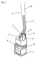
- the FIG. 1 shows a fully assembled connector with a two-part connector housing.
- the connector housing consists of a first and a second housing part 1, 2, which are interconnected via latching elements 8, 9.
- the locking elements 8, 9 are here exemplified by locking lugs 8 on the first housing part 1 and locking tabs 9 on the second housing part 2 realized.
- the two housing parts 1, 2 can in principle also be connected to one another in other ways, for example by gluing or welding, but the locking proposed here is a preferred method of connection that is particularly simple to carry out.
- the second housing part 2 forms a housing cap for the first housing part 1 and has a recess 4, through which a connecting line 3 is passed.
- the connecting line 3 is in electrical connection to electrical components, not shown here, in particular plug-in contact elements in the first housing part 1.
- the recess 4 is largely covered by a sword-shaped Anformung 5, which, as particularly clear in the FIG. 2 can be seen, is integrally formed with the first housing part 1.
- the sword-shaped Anformung 5 thus reduces the recess 4 except for a small lead-through area 6 which is surrounded by a not completely closed annular collar 7, which is integrally formed on the second housing part 2.
- the free end portion of the sword-like Anformung 5 extends to the collar 7, which is thereby closed to a complete ring.
- the connecting line 3, which forms a bundle of individual conductor wires 11 in the lead-through region 6, is clamped between the sword-shaped projection 5 and the collar 7.
- FIG. 2 shows the first housing part 1 of the multi-pin connector, which holds one of the number of poles corresponding number of plug contact elements, such as, for example, in the figure socket contacts, not shown.
- a line core 11 of the connecting line 3 is electrically and mechanically connected to the plug-in contact elements, as a result of which the first housing part 1 is also mechanically fixedly coupled to the connecting line 3.
- the connecting line 3 To connect the second housing part 2 as a housing cap with the top of the first housing part 1, the connecting line 3 must first be passed through the recess 4 of the second housing part 2 therethrough. Since the conductor wires 11 of the connecting line 3 are already connected to the first housing part 1, there is only the possibility of postponing the second housing part 2 from the free side of the connecting line 3 via the sheathing 10 in the direction of the first housing part 1. To enable this without much effort, the diameter of the recess 4 is made larger than the cross-sectional diameter of the sheath 10 of the connecting line 3, so that the second housing part can be pushed virtually frictionless over the connecting line 3.
- the first housing part 1 which in the FIGS. 2 and 3 is shown, so pass through the exposed cable wires 11 of the connecting line 3, the recess 4 of the second housing part 2, which together have a substantially smaller cross-section than that Sheath 10 of the connecting line 3. Since the core wires 11 are not able to fill the recess 4 approximately, a relatively large area of the recess 4 remains as a free space through which relatively large foreign particles could penetrate into the connector housing.
Landscapes
- Connector Housings Or Holding Contact Members (AREA)
Description
- Die Erfindung betrifft ein Steckverbindergehäuse, mit einem elektrische Komponenten aufweisenden ersten Gehäuseteil und einem eine Gehäusekappe ausbildenden zweiten Gehäuseteil, welches mit dem ersten Gehäuseteil verbindbar ist, und mit einer Ausnehmung im zweiten Gehäuseteil, durch die eine elektrischen Anschlussleitung zur elektrischen Anbindung elektrischer Komponenten des ersten Gehäuseteils hindurchführbar ist. Die Erfindung betrifft außerdem einen Steckverbinder mit einem solchen Steckverbindergehäuse.
- Gehäuse von elektrischen Steckverbindern sind in häufig zweiteilig aufgebaut, wobei ein erstes Gehäuseteil als Halter von Steckhülsenkontakten oder Steckerstiften, die im folgenden zusammenfassend als Steckkontaktelemente bezeichnet werden, vorgesehen ist, und ein zweites Gehäuseteil eine Gehäusekappe ausbildet, die mit dem ersten Gehäuseteil verbunden werden kann und die das erste Gehäuseteil abschließt. Dadurch sind die im Inneren des Gehäuses angeordneten Steckkontakte oder sonstigen elektrischen Komponenten vor Umwelteinflüssen geschützt. Zumeist weist die Gehäusekappe eine Ausnehmung auf, durch die eine Anschlussleitung hindurchführbar ist.
- Im Allgemeinen ist es erwünscht, dass das Innere des mit einer Anschlussleitung versehenen Steckverbindergehäuses - diese Kombination wird im Folgenden kurz als Steckverbinder bezeichnet - möglichst gut gegen Umwelteinflüsse geschützt ist. Eine flüssigkeitsdichte Kapselung ist dabei nicht immer nötig; ein Mindesterfordernis ist aber häufig, dass die elektrischen Komponenten vor leitenden Feststoffpartikeln, insbesondere vor metallischen Spänen, welche Kurzschlüsse bewirken können, geschützt sind.
- Dies erfordert, dass der Querschnitt der Anschlussleitung die Ausnehmung des zweiten Gehäuseteils möglichst dicht ausfüllt oder dass ein zusätzliches Abdichtmittel, wie etwa eine Gummidichtung in oder um die Ausnehmung herum angeordnet wird. Beide Maßnahmen erhöhen aber den Kosten- und Montageaufwand des Steckverbinders.
- Üblich ist es, Steckkontaktelemente, die am ersten Gehäuseteil angeordnet sind, mit den Leitungsadern einer Anschlussleitung vorzukonfektionieren. Zum Fertigstellen des Steckverbinders muss dann abschließend noch die Gehäusekappe über die Anschlussleitung geschoben werden, wobei die Anschlussleitung durch die Ausnehmung an der Gehäusekappe geführt wird. Dieser Montageschritt wird durch eine die Anschlussleitung eng umfassende Ausnehmung stark erschwert. Noch schwieriger ist das Aufschieben der Gehäusekappe, wenn diese eine Gummidichtung aufweist.
- Noch problematischer ist es, wenn die Anschlussleitung mit einer Ummantelung versehen ist, die am Ende der Anschlussleitung entfernt ist, um die von der Ummantelung umgebenen Leitungsadern einzeln an Steckkontaktelemente oder sonstige elektrischen Komponenten des ersten Gehäuseteils anzuschließen. Hieraus ergibt sich das Problem, dass beim montierten Steckverbinder durch die Ausnehmung des zweiten Gehäuseteils ein Bündel von einzelnen Leitungsadern hindurchgeführt ist, die zusammen aber einen deutlichen kleineren Querschnitt aufweisen als der ummantelte Bereich der Anschlussleitung. Da die Weite der Ausnehmung aber auf den ummantelten Bereich der Anschlussleitung abgestimmt ist, verbleibt in der Ausnehmung ein relativ großer nicht ausgefüllter Bereich. Hierdurch ist der montierte Steckverbinder in vielen Fällen gegen das Eindringen elektrisch leitender Feststoffpartikel nicht ausreichend gut abgedichtet,
WO2004001962 A1 zeigt ein Steckverbindergehäuse nach dem Oberbegriff des Anspruchs 1. - Es stellte sich die Aufgabe, ein Steckverbindergehäuse zu schaffen, welches auf einfache und kostengünstige Weise die vorgenannten Nachteile vermeidet.
- Diese Aufgabe wird erfindungsgemäß durch die Merkmale des Anspruchs 1 gelöst.
- Die Erfindung ermöglicht es, dass die Weite der Ausnehmung am zweiten Gehäuseteil deutlich größer ausgeführt sein kann als der Querschnitt der Anschlussleitung, so dass die Anschlussleitung ohne einen großen, durch Reibung verursachten Kraftaufwand durch die Ausnehmung hindurchgeführt werden kann. Um dennoch eine gute Abdichtung zu erzielen, ist erfindungsgemäß am ersten Gehäuseteil eine schwertartige Anformung vorgesehen, welche nach dem Verbinden der beiden Gehäuseteile die Ausnehmung größtenteils abdeckt. Hierdurch verbleibt nur noch ein kleiner Teil der Ausnehmung als Durchführungsbereich der Anschlussleitung, die zudem durch die schwertförmige Anformung in diesem Bereich zusammengepresst werden kann. Auf diese Weise wird selbst dann eine gute Abdichtung erreicht, wenn die Anschlussleitung als ein Bündel einzelner Leitungsadern aus dem Steckverbindergehäuse herausgeführt wird. Steckverbinder mit einem derartigen Steckverbindergehäuse können vorteilhaft beispielsweise in Getriebegehäusen von Kraftfahrzeugen unter Öl eingesetzt werden. Das Eindringen von Öl in das Steckverbindergehäuse ist dabei unproblematisch, solange dieses keine elektrisch leitfähigen Teile wie etwa abgeriebene Späne mit sich führt. Durch die erfindungsgemäße Ausgestaltung wird eine spandichte Abdichtung des Steckverbindergehäuses erreicht.
- Weitere Einzelheiten der Erfindung ergeben sich aus den abhängigen Ansprüche und der nachfolgenden Beschreibung eines Ausführungsbeispiels anhand der Zeichnung. Es zeigen die
- Figur 1
- einen fertig montierten Steckverbinder mit einem erfindungsgemäßen Steckverbindergehäuse,
- Figuren 2 bis 4
- Montagephasen des Steckverbinders.
- Die
Figur 1 zeigt einen fertig montierten Steckverbinder mit einem zweiteilig ausgeführten Steckverbindergehäuse. Das Steckverbindergehäuse besteht aus einem ersten und einem zweiten Gehäuseteil 1, 2, die über Rastelemente 8, 9 miteinander verbunden. Die Rastelemente 8, 9 sind hier beispielhaft durch Rastnasen 8 am ersten Gehäuseteil 1 und Rastlaschen 9 am zweiten Gehäuseteil 2 realisiert. Die beiden Gehäuseteile 1, 2 können grundsätzlich auch auf andere Weise, etwa durch Verkleben oder Verschweißen, miteinander verbunden sein, wobei aber das hier vorgeschlagene Verrasten eine bevorzugte, weil besonders einfach ausführbare Verbindungsmethode ist. - Das zweite Gehäuseteil 2 bildet eine Gehäusekappe für das erste Gehäuseteil 1 aus und weist eine Ausnehmung 4 auf, durch die eine Anschlussleitung 3 hindurchgeführt ist. Die Anschlussleitung 3 steht in elektrischer Verbindung zu hier nicht dargestellten elektrischen Komponenten, wie insbesondere Steckkontaktelementen im ersten Gehäuseteil 1. Die Ausnehmung 4 wird größtenteils durch eine schwertförmige Anformung 5 abgedeckt, die, wie besonders deutlich in der
Figur 2 erkennbar ist, einstückig mit dem ersten Gehäuseteil 1 ausgebildet ist. - Die schwertförmige Anformung 5 verkleinert so die Ausnehmung 4 bis auf einen kleinen Durchführungsbereich 6, der von einem nicht vollständig geschlossenen ringförmigen Kragen 7 umgeben ist, welcher am zweiten Gehäuseteil 2 angeformt ist. Bei miteinander verbundenen Gehäuseteilen 1, 2 erstreckt sich der freie Endabschnitt der schwertartigen Anformung 5 bis zu dem Kragen 7, der dadurch zu einem vollständigen Ring geschlossen wird. Dadurch wird die Anschlussleitung 3, die in dem Durchführungsbereich 6 ein Bündel von einzelnen Leitungsadern 11 ausbildet, zwischen der schwertförmigen Anformung 5 und dem Kragen 7 klemmend gehalten.
- In den
Figuren 2 bis 4 sind drei Montagephasen des Steckverbinders dargestellt. DieFigur 2 zeigt das erste Gehäuseteil 1 des mehrpoligen Steckverbinders, welches eine der Polzahl entsprechende Anzahl von Steckkontaktelementen, wie beispielsweise in der Figur nicht dargestellte Steckhülsenkontakte, haltert. Mit den Steckkontaktelementen ist jeweils eine Leitungsader 11 der Anschlussleitung 3 elektrisch und mechanisch verbunden, wodurch auch das erste Gehäuseteil 1 mechanisch fest an die Anschlussleitung 3 gekoppelt ist. - Um das zweite Gehäuseteil 2 als Gehäusekappe mit der Oberseite des ersten Gehäuseteil 1 zu verbinden, muss zunächst die Anschlussleitung 3 durch die Ausnehmung 4 des zweiten Gehäuseteils 2 hindurch geführt werden. Da die Leitungsadern 11 der Anschlussleitung 3 schon mit dem ersten Gehäuseteil 1 verbunden sind, besteht hierzu nur die Möglichkeit, das zweite Gehäuseteil 2 von der freien Seite der Anschlussleitung 3 her über deren Ummantelung 10 in Richtung auf das erste Gehäuseteil 1 aufzuschieben. Um dies ohne großen Kraftaufwand zu ermöglichen, ist der Durchmesser der Ausnehmung 4 größer ausgeführt als der Querschnittsdurchmesser der Ummantelung 10 der Anschlussleitung 3, so dass das zweite Gehäuseteil praktisch reibungsfrei über die Anschlussleitung 3 geschoben werden kann.
- Erreicht das zweite Gehäuseteil 2 das erste Gehäuseteil 1, was in den
Figuren 2 und 3 dargestellt ist, so durchgreifen die freiliegenden Leitungsadern 11 der Anschlussleitung 3 die Ausnehmung 4 des zweiten Gehäuseteils 2, welche aber zusammen einen wesentlich kleineren Querschnitt aufweisen als die Ummantelung 10 der Anschlussleitung 3. Da die Leitungsadern 11 die Ausnehmung 4 nicht annähernd auszufüllen vermögen, verbleibt ein relativ großer Bereich der Ausnehmung 4 als ein Freiraum, durch die auch relativ große Fremdpartikel in das Steckverbindergehäuse eindringen könnten. - Dieser Freiraum wird aber im Verlauf des weiteren Zusammenfügens der beiden Gehäuseteile 1, 2 zunehmend durch die schwertförmige Anformung 5 des ersten Gehäuseteils 1 ausgefüllt. Haben die beiden Gehäuseteile 1, 2 ihre Endpositionen relativ zueinander erreicht, so verrasten die Rastelemente 8, 9 der beiden Gehäuseteile 1, 2 miteinander und bilden zusammen ein vollständiges Steckverbindergehäuse aus. Damit ist der bereits in der
Figur 1 dargestellte Montagezustand erreicht. Die schwertförmige Anformung 5 deckt nur die Ausnehmung 4 fast vollständig ab und drängt die Leitungsadern 11 in den kleinen Durchführungsbereich 6, der von dem ringförmigen Kragen 7 umgeben ist. Wie dieFigur 1 zeigt presst die schwertförmige Anformung 5 die Leitungsadern 11 gegen den Rand des Kragens 7. Hierdurch ist der Durchführungsbereich 6 der Leitungsadern 11 weitgehend, das heißt, zwar nicht flüssigkeitsdicht, aber doch gegen das Eindringen makroskopischer Feststoffpartikel, abgedichtet. -
- 1
- erstes Gehäuseteil
- 2
- zweites Gehäuseteil (Gehäusekappe)
- 3
- Anschlussleitung
- 4
- Ausnehmung
- 5
- (schwertartige) Anformung
- 6
- Durchführungsbereich
- 7
- (ringförmiger) Kragen
- 8
- Rastnasen (Rastelement)
- 9
- Rastlaschen (Rastelement)
- 10
- Ummantelung
- 11
- Leitungsader(n)
Claims (6)
- Steckverbindergehäuse
mit einem elektrische Komponenten aufweisenden ersten Gehäuseteil (1) und einem eine Gehäusekappe ausbildenden zweiten Gehäuseteil (2), welches mit dem ersten Gehäuseteil (1) verbindbar ist, und
mit einer Ausnehmung (4) im zweiten Gehäuseteil (2), dadurch gekennzeichnet, dass die Ausnehmung (4) im zweiten Gehäuseteil (2) durch das zweite Gehäuseteil (2) geschlossen umrandet ist, wobei durch die Ausnehmung (4) eine elektrische
Anschlussleitung (3) zur elektrischen Anbindung elektrischer Komponenten des ersten Gehäuseteils (1) hindurchführbar ist,
wobei
das erste Gehäuseteil (1) eine schwertartige Anformung (5) aufweist, welche nach dem Verbinden des zweiten Gehäuseteils (2) mit dem ersten Gehäuseteils (1) die Ausnehmung (4) größtenteils abdeckt. - Steckverbindergehäuse nach Anspruch 1, dadurch gekennzeichnet, dass die schwertartige Anformung (5) den zur Durchführung der Anschlussleitung (3) nicht benötigten Bereich der Ausnehmung (4) abdeckt.
- Steckverbindergehäuse nach Anspruch 1, dadurch gekennzeichnet, dass das zweite Gehäuseteil (2) mit dem ersten Gehäuseteil über Rastelemente (8, 9) verbindbar ist.
- Steckverbinder mit einem Steckverbindergehäuse nach Anspruch 1, dadurch gekennzeichnet, dass nach dem Verbinden des ersten und des zweiten Gehäuseteils (1, 2) Abschnitte der Anschlussleitung (3) zwischen der schwertartigen Anformung (5) des ersten Gehäuseteils (1) und dem zweiten Gehäuseteil (2) eingepresst ist.
- Steckverbinder nach Anspruch 4, dadurch gekennzeichnet, dass das zweite Gehäuseteil (2) an der Austrittsstelle der Anschlussleitung (3) einen Kragen (7) besitzt, der einen nicht vollständig geschlossenen ringförmigen Randabschnitt aufweist, der durch die schwertartigen Anformung (5) abgeschlossen ist.
- Steckverbinder mit einem Steckverbindergehäuse nach Anspruch 1,
dadurch gekennzeichnet, dass der Steckverbinder zur Verwendung in einem ölgefüllten Getriebegehäuse eines Kraftfahrzeugs geeignet ist.
Applications Claiming Priority (2)
| Application Number | Priority Date | Filing Date | Title |
|---|---|---|---|
| DE102012009877A DE102012009877A1 (de) | 2012-05-18 | 2012-05-18 | Steckverbindergehäuse und Steckverbinder |
| PCT/EP2013/059586 WO2013171111A1 (de) | 2012-05-18 | 2013-05-08 | Steckverbindergehäuse und steckverbinder |
Publications (2)
| Publication Number | Publication Date |
|---|---|
| EP2850700A1 EP2850700A1 (de) | 2015-03-25 |
| EP2850700B1 true EP2850700B1 (de) | 2016-10-12 |
Family
ID=48325733
Family Applications (1)
| Application Number | Title | Priority Date | Filing Date |
|---|---|---|---|
| EP13720964.9A Active EP2850700B1 (de) | 2012-05-18 | 2013-05-08 | Steckverbindergehäuse und steckverbinder |
Country Status (6)
| Country | Link |
|---|---|
| US (1) | US9209553B2 (de) |
| EP (1) | EP2850700B1 (de) |
| JP (1) | JP6371274B2 (de) |
| DE (1) | DE102012009877A1 (de) |
| ES (1) | ES2606654T3 (de) |
| WO (1) | WO2013171111A1 (de) |
Families Citing this family (7)
| Publication number | Priority date | Publication date | Assignee | Title |
|---|---|---|---|---|
| DE102012013948A1 (de) | 2012-07-13 | 2014-01-16 | Kostal Kontakt Systeme Gmbh | Elektrische Steckverbinderanordnung |
| DE102013101123B4 (de) * | 2013-02-05 | 2019-06-27 | HARTING Electronics GmbH | Steckverbindergehäuse |
| DE102014008343A1 (de) * | 2014-06-04 | 2015-12-17 | Kostal Kontakt Systeme Gmbh | Elektrisches Gerät |
| JP1532486S (de) * | 2014-11-25 | 2015-08-31 | ||
| JP6558991B2 (ja) * | 2015-07-22 | 2019-08-14 | 矢崎総業株式会社 | コネクタ付き電線 |
| US10530103B2 (en) | 2017-03-24 | 2020-01-07 | Alpine Electronics, Inc. | Structure of electrical connector casing |
| DE102022120486A1 (de) * | 2022-08-12 | 2024-02-15 | Lisa Dräxlmaier GmbH | Gewinkelter mehrpoliger steckverbinder |
Family Cites Families (40)
| Publication number | Priority date | Publication date | Assignee | Title |
|---|---|---|---|---|
| US3112148A (en) * | 1962-01-12 | 1963-11-26 | Jasper Blackburn Corp | Protective sheath for an electric connector |
| US3683314A (en) * | 1971-01-21 | 1972-08-08 | Bunker Ramo | Cable junction box |
| US4229616A (en) * | 1978-08-10 | 1980-10-21 | Hotchkiss Kenneth W | Cable connector cover |
| US4382649A (en) * | 1981-01-12 | 1983-05-10 | Communication Systems, Inc. | Multiple cable connector box |
| US4449015A (en) * | 1981-05-18 | 1984-05-15 | Proto Production Plastics, Inc. | Connector cover with multiple mounting means |
| US4444447A (en) * | 1982-05-24 | 1984-04-24 | Minnesota Mining And Manufacturing Company | Electrical wire connector |
| US4749363A (en) * | 1987-03-12 | 1988-06-07 | Robert Luska | Extension cord safety box |
| JPH0748387B2 (ja) * | 1987-10-19 | 1995-05-24 | 矢崎総業株式会社 | コネクタ |
| JP2543150Y2 (ja) * | 1991-03-29 | 1997-08-06 | 古河電気工業株式会社 | フラットケーブルの接続部構造 |
| US5129839A (en) * | 1991-11-20 | 1992-07-14 | Doskocil Manufacturing Company, Inc. | Extension cord connection housing |
| FR2689329B1 (fr) * | 1992-03-30 | 1994-07-22 | Interco Sa | Procede et dispositif de terminaison de cables electriques installes dans un immeuble pour connexion ulterieure. |
| JPH06163090A (ja) * | 1992-11-25 | 1994-06-10 | Yazaki Corp | コネクタ |
| US5371323B1 (en) * | 1993-03-10 | 1997-07-29 | Keptel Inc | Splice housing apparatus |
| GB9318256D0 (en) * | 1993-09-03 | 1993-10-20 | Raychem Sa Nv | A coaxial cable connector housing |
| JP2926676B2 (ja) * | 1993-09-24 | 1999-07-28 | 矢崎総業株式会社 | ハウジング結合型コネクタ |
| US5804770A (en) * | 1995-09-19 | 1998-09-08 | Sumitomo Wiring Systems, Ltd. | Cover equipped electrical connection device and a cover for an electrical connection device |
| JP3512084B2 (ja) * | 1997-04-18 | 2004-03-29 | 住友電装株式会社 | ゴムブーツ |
| CA2261307A1 (en) * | 1997-05-22 | 1998-11-26 | Mark R. Drane | Cable splice closure |
| US6213808B1 (en) * | 1998-10-13 | 2001-04-10 | Gregory Jay Whatmore | Method of joining electrical conductors and an apparatus for practicing this method |
| US6099340A (en) * | 1998-12-09 | 2000-08-08 | Florentine; Angela | Waterproof container for electrical plugs and sockets |
| NL1011376C2 (nl) * | 1999-02-23 | 2000-08-24 | Framatome Connectors Belgium | Kabelconnector en werkwijze voor het aansluiten van een kabel op een kabelconnector. |
| US6234823B1 (en) * | 1999-03-29 | 2001-05-22 | Paul Martin Fuess | Plug adapter having eccentric ring driving cord retention wedge |
| TW490090U (en) * | 2001-03-28 | 2002-06-01 | All Line Inc | Socket with a lid shell |
| US6547600B2 (en) * | 2001-07-16 | 2003-04-15 | Chun Chang Yen | Engaging structure for electrical wires of a plug |
| DE20114120U1 (de) * | 2001-08-27 | 2003-01-23 | Compagnie Deutsch GmbH, 82152 Planegg | Zugentlastungsvorrichtung für ein elektrisches Kabel |
| US6752646B2 (en) * | 2001-08-27 | 2004-06-22 | Dekko Technologies, Inc. | Compressor plug cap assembly |
| WO2004001962A1 (en) * | 2002-06-19 | 2003-12-31 | The Siemon Company | Video balun |
| DE20304555U1 (de) * | 2003-03-21 | 2003-10-09 | Tyco Electronics Nederland B.V., Hertogenbosch | Kabelstecker mit verbesserter Kabelabdichtung und Zugentlastung |
| US7044776B2 (en) * | 2003-12-02 | 2006-05-16 | King Jr Lloyd Herbert | Wire connector |
| US6955558B1 (en) * | 2004-04-26 | 2005-10-18 | Andrew Corporation | Cable and apparatus interface security device |
| US7083472B2 (en) * | 2004-06-10 | 2006-08-01 | Commscope Solutions Properties, Llc | Shielded jack assemblies and methods for forming a cable termination |
| US7189100B1 (en) * | 2005-02-18 | 2007-03-13 | Colbourne Jerome G | Cord retaining housing and method |
| USD616058S1 (en) * | 2008-10-31 | 2010-05-18 | Detnet South Africa (Pty) Limited | Detonator connector |
| JP5218850B2 (ja) * | 2009-03-23 | 2013-06-26 | 住友電装株式会社 | コネクタ |
| US8016607B2 (en) * | 2010-01-08 | 2011-09-13 | Lear Corporation | Connector assembly for electric vehicle charging |
| US8025510B2 (en) * | 2010-02-24 | 2011-09-27 | Mikhail Bolshakov | Tethered port protector for portable electronic devices and kit of port protectors |
| JP5560949B2 (ja) * | 2010-06-23 | 2014-07-30 | 住友電装株式会社 | 端子カバー |
| DE102011014215B4 (de) * | 2011-03-17 | 2012-10-18 | Phoenix Contact Gmbh & Co. Kg | Kabelgehäuse |
| CA2844133C (en) * | 2011-08-29 | 2016-06-28 | Midwest Innovative Products, Llc | Electrical cord connection covering techniques |
| US8870587B2 (en) * | 2011-08-29 | 2014-10-28 | Midwest Innovative Products, Llc | Electrical cord connection covering techniques |
-
2012
- 2012-05-18 DE DE102012009877A patent/DE102012009877A1/de not_active Withdrawn
-
2013
- 2013-05-08 JP JP2015511996A patent/JP6371274B2/ja active Active
- 2013-05-08 ES ES13720964.9T patent/ES2606654T3/es active Active
- 2013-05-08 WO PCT/EP2013/059586 patent/WO2013171111A1/de not_active Ceased
- 2013-05-08 EP EP13720964.9A patent/EP2850700B1/de active Active
-
2014
- 2014-08-29 US US14/472,879 patent/US9209553B2/en active Active
Non-Patent Citations (1)
| Title |
|---|
| None * |
Also Published As
| Publication number | Publication date |
|---|---|
| ES2606654T3 (es) | 2017-03-27 |
| DE102012009877A1 (de) | 2013-11-21 |
| JP2015521348A (ja) | 2015-07-27 |
| US9209553B2 (en) | 2015-12-08 |
| US20140370744A1 (en) | 2014-12-18 |
| WO2013171111A1 (de) | 2013-11-21 |
| EP2850700A1 (de) | 2015-03-25 |
| JP6371274B2 (ja) | 2018-08-08 |
Similar Documents
| Publication | Publication Date | Title |
|---|---|---|
| WO2013171111A1 (de) | Steckverbindergehäuse und steckverbinder | |
| DE112008000565T5 (de) | Abschirmschale | |
| EP3959781B1 (de) | Steckverbinder und steckverbinderanornung | |
| DE112017000228T5 (de) | Verbinder | |
| DE102008006340A1 (de) | Steckverbindungsanordnung mit aufgeformtem abgeschirmtem Gehäuse | |
| EP2599163B1 (de) | Elektrische verbindung | |
| EP2351161A1 (de) | Elektrisches steckverbindungssystem | |
| DE112018001914B4 (de) | Innenleiteranschluss und abgeschirmter Verbinder | |
| DE112014002122T5 (de) | Verbinder | |
| EP3416248A1 (de) | Kabeldurchführung | |
| EP3869622A1 (de) | Ladebuchse für ein elektrofahrzeug | |
| DE202012010451U1 (de) | Steckverbinder mit Isolierteil | |
| EP3416249A2 (de) | Kabeldurchführung und steuervorrichtung | |
| WO2010091985A1 (de) | Steckbare anschlussvorrichtung zum anschluss eines kabels an ein anschlussgehäuse | |
| EP4569576A1 (de) | Gewinkelter mehrpoliger steckverbinder | |
| EP3340392B1 (de) | Anordnung zum verbinden von elektrischen leitungen | |
| DE10054501C2 (de) | Kabeleinführung | |
| EP2467904B1 (de) | Kontaktelement | |
| DE102014203701B4 (de) | Wasserdichte Struktur für einen Anschluss | |
| EP2731206A1 (de) | Verbinder und Verfahren zur Montage | |
| DE102017220944A1 (de) | Elektrischer Steckverbinder für ein mehradriges elektrisches Kabel | |
| EP3477777A1 (de) | Elektrische leitung mit schirmausleitung | |
| DE102011077886B4 (de) | Verfahren zur Leitungskonfektionierung | |
| DE102005006145B4 (de) | Kabelgehäuse und elektrische Verbindung für abgeschirmte Kabel | |
| DE112022003035T5 (de) | Elektrische Verbindereinheit |
Legal Events
| Date | Code | Title | Description |
|---|---|---|---|
| PUAI | Public reference made under article 153(3) epc to a published international application that has entered the european phase |
Free format text: ORIGINAL CODE: 0009012 |
|
| 17P | Request for examination filed |
Effective date: 20141212 |
|
| AK | Designated contracting states |
Kind code of ref document: A1 Designated state(s): AL AT BE BG CH CY CZ DE DK EE ES FI FR GB GR HR HU IE IS IT LI LT LU LV MC MK MT NL NO PL PT RO RS SE SI SK SM TR |
|
| AX | Request for extension of the european patent |
Extension state: BA ME |
|
| DAX | Request for extension of the european patent (deleted) | ||
| GRAP | Despatch of communication of intention to grant a patent |
Free format text: ORIGINAL CODE: EPIDOSNIGR1 |
|
| INTG | Intention to grant announced |
Effective date: 20160425 |
|
| GRAP | Despatch of communication of intention to grant a patent |
Free format text: ORIGINAL CODE: EPIDOSNIGR1 |
|
| INTG | Intention to grant announced |
Effective date: 20160608 |
|
| GRAP | Despatch of communication of intention to grant a patent |
Free format text: ORIGINAL CODE: EPIDOSNIGR1 |
|
| INTG | Intention to grant announced |
Effective date: 20160715 |
|
| GRAS | Grant fee paid |
Free format text: ORIGINAL CODE: EPIDOSNIGR3 |
|
| GRAA | (expected) grant |
Free format text: ORIGINAL CODE: 0009210 |
|
| AK | Designated contracting states |
Kind code of ref document: B1 Designated state(s): AL AT BE BG CH CY CZ DE DK EE ES FI FR GB GR HR HU IE IS IT LI LT LU LV MC MK MT NL NO PL PT RO RS SE SI SK SM TR |
|
| REG | Reference to a national code |
Ref country code: GB Ref legal event code: FG4D Free format text: NOT ENGLISH |
|
| REG | Reference to a national code |
Ref country code: CH Ref legal event code: EP |
|
| REG | Reference to a national code |
Ref country code: AT Ref legal event code: REF Ref document number: 837251 Country of ref document: AT Kind code of ref document: T Effective date: 20161015 |
|
| REG | Reference to a national code |
Ref country code: IE Ref legal event code: FG4D Free format text: LANGUAGE OF EP DOCUMENT: GERMAN |
|
| REG | Reference to a national code |
Ref country code: DE Ref legal event code: R096 Ref document number: 502013004956 Country of ref document: DE |
|
| REG | Reference to a national code |
Ref country code: LT Ref legal event code: MG4D |
|
| REG | Reference to a national code |
Ref country code: NL Ref legal event code: MP Effective date: 20161012 |
|
| PG25 | Lapsed in a contracting state [announced via postgrant information from national office to epo] |
Ref country code: LV Free format text: LAPSE BECAUSE OF FAILURE TO SUBMIT A TRANSLATION OF THE DESCRIPTION OR TO PAY THE FEE WITHIN THE PRESCRIBED TIME-LIMIT Effective date: 20161012 |
|
| PG25 | Lapsed in a contracting state [announced via postgrant information from national office to epo] |
Ref country code: NO Free format text: LAPSE BECAUSE OF FAILURE TO SUBMIT A TRANSLATION OF THE DESCRIPTION OR TO PAY THE FEE WITHIN THE PRESCRIBED TIME-LIMIT Effective date: 20170112 Ref country code: GR Free format text: LAPSE BECAUSE OF FAILURE TO SUBMIT A TRANSLATION OF THE DESCRIPTION OR TO PAY THE FEE WITHIN THE PRESCRIBED TIME-LIMIT Effective date: 20170113 Ref country code: LT Free format text: LAPSE BECAUSE OF FAILURE TO SUBMIT A TRANSLATION OF THE DESCRIPTION OR TO PAY THE FEE WITHIN THE PRESCRIBED TIME-LIMIT Effective date: 20161012 Ref country code: SE Free format text: LAPSE BECAUSE OF FAILURE TO SUBMIT A TRANSLATION OF THE DESCRIPTION OR TO PAY THE FEE WITHIN THE PRESCRIBED TIME-LIMIT Effective date: 20161012 |
|
| REG | Reference to a national code |
Ref country code: FR Ref legal event code: PLFP Year of fee payment: 5 |
|
| PG25 | Lapsed in a contracting state [announced via postgrant information from national office to epo] |
Ref country code: FI Free format text: LAPSE BECAUSE OF FAILURE TO SUBMIT A TRANSLATION OF THE DESCRIPTION OR TO PAY THE FEE WITHIN THE PRESCRIBED TIME-LIMIT Effective date: 20161012 Ref country code: NL Free format text: LAPSE BECAUSE OF FAILURE TO SUBMIT A TRANSLATION OF THE DESCRIPTION OR TO PAY THE FEE WITHIN THE PRESCRIBED TIME-LIMIT Effective date: 20161012 Ref country code: IS Free format text: LAPSE BECAUSE OF FAILURE TO SUBMIT A TRANSLATION OF THE DESCRIPTION OR TO PAY THE FEE WITHIN THE PRESCRIBED TIME-LIMIT Effective date: 20170212 Ref country code: RS Free format text: LAPSE BECAUSE OF FAILURE TO SUBMIT A TRANSLATION OF THE DESCRIPTION OR TO PAY THE FEE WITHIN THE PRESCRIBED TIME-LIMIT Effective date: 20161012 Ref country code: PT Free format text: LAPSE BECAUSE OF FAILURE TO SUBMIT A TRANSLATION OF THE DESCRIPTION OR TO PAY THE FEE WITHIN THE PRESCRIBED TIME-LIMIT Effective date: 20170213 Ref country code: PL Free format text: LAPSE BECAUSE OF FAILURE TO SUBMIT A TRANSLATION OF THE DESCRIPTION OR TO PAY THE FEE WITHIN THE PRESCRIBED TIME-LIMIT Effective date: 20161012 Ref country code: HR Free format text: LAPSE BECAUSE OF FAILURE TO SUBMIT A TRANSLATION OF THE DESCRIPTION OR TO PAY THE FEE WITHIN THE PRESCRIBED TIME-LIMIT Effective date: 20161012 |
|
| REG | Reference to a national code |
Ref country code: DE Ref legal event code: R097 Ref document number: 502013004956 Country of ref document: DE |
|
| PG25 | Lapsed in a contracting state [announced via postgrant information from national office to epo] |
Ref country code: RO Free format text: LAPSE BECAUSE OF FAILURE TO SUBMIT A TRANSLATION OF THE DESCRIPTION OR TO PAY THE FEE WITHIN THE PRESCRIBED TIME-LIMIT Effective date: 20161012 Ref country code: DK Free format text: LAPSE BECAUSE OF FAILURE TO SUBMIT A TRANSLATION OF THE DESCRIPTION OR TO PAY THE FEE WITHIN THE PRESCRIBED TIME-LIMIT Effective date: 20161012 Ref country code: SK Free format text: LAPSE BECAUSE OF FAILURE TO SUBMIT A TRANSLATION OF THE DESCRIPTION OR TO PAY THE FEE WITHIN THE PRESCRIBED TIME-LIMIT Effective date: 20161012 Ref country code: EE Free format text: LAPSE BECAUSE OF FAILURE TO SUBMIT A TRANSLATION OF THE DESCRIPTION OR TO PAY THE FEE WITHIN THE PRESCRIBED TIME-LIMIT Effective date: 20161012 |
|
| PLBE | No opposition filed within time limit |
Free format text: ORIGINAL CODE: 0009261 |
|
| STAA | Information on the status of an ep patent application or granted ep patent |
Free format text: STATUS: NO OPPOSITION FILED WITHIN TIME LIMIT |
|
| PG25 | Lapsed in a contracting state [announced via postgrant information from national office to epo] |
Ref country code: LU Free format text: LAPSE BECAUSE OF NON-PAYMENT OF DUE FEES Effective date: 20170531 Ref country code: SM Free format text: LAPSE BECAUSE OF FAILURE TO SUBMIT A TRANSLATION OF THE DESCRIPTION OR TO PAY THE FEE WITHIN THE PRESCRIBED TIME-LIMIT Effective date: 20161012 Ref country code: BG Free format text: LAPSE BECAUSE OF FAILURE TO SUBMIT A TRANSLATION OF THE DESCRIPTION OR TO PAY THE FEE WITHIN THE PRESCRIBED TIME-LIMIT Effective date: 20170112 |
|
| 26N | No opposition filed |
Effective date: 20170713 |
|
| PG25 | Lapsed in a contracting state [announced via postgrant information from national office to epo] |
Ref country code: SI Free format text: LAPSE BECAUSE OF FAILURE TO SUBMIT A TRANSLATION OF THE DESCRIPTION OR TO PAY THE FEE WITHIN THE PRESCRIBED TIME-LIMIT Effective date: 20161012 |
|
| REG | Reference to a national code |
Ref country code: CH Ref legal event code: PL |
|
| PG25 | Lapsed in a contracting state [announced via postgrant information from national office to epo] |
Ref country code: MC Free format text: LAPSE BECAUSE OF FAILURE TO SUBMIT A TRANSLATION OF THE DESCRIPTION OR TO PAY THE FEE WITHIN THE PRESCRIBED TIME-LIMIT Effective date: 20161012 |
|
| REG | Reference to a national code |
Ref country code: IE Ref legal event code: MM4A |
|
| PG25 | Lapsed in a contracting state [announced via postgrant information from national office to epo] |
Ref country code: LI Free format text: LAPSE BECAUSE OF NON-PAYMENT OF DUE FEES Effective date: 20170531 Ref country code: CH Free format text: LAPSE BECAUSE OF NON-PAYMENT OF DUE FEES Effective date: 20170531 |
|
| PG25 | Lapsed in a contracting state [announced via postgrant information from national office to epo] |
Ref country code: LU Free format text: LAPSE BECAUSE OF NON-PAYMENT OF DUE FEES Effective date: 20170508 |
|
| REG | Reference to a national code |
Ref country code: BE Ref legal event code: MM Effective date: 20170531 |
|
| PG25 | Lapsed in a contracting state [announced via postgrant information from national office to epo] |
Ref country code: IE Free format text: LAPSE BECAUSE OF NON-PAYMENT OF DUE FEES Effective date: 20170508 |
|
| REG | Reference to a national code |
Ref country code: FR Ref legal event code: PLFP Year of fee payment: 6 |
|
| PG25 | Lapsed in a contracting state [announced via postgrant information from national office to epo] |
Ref country code: BE Free format text: LAPSE BECAUSE OF NON-PAYMENT OF DUE FEES Effective date: 20170531 |
|
| PG25 | Lapsed in a contracting state [announced via postgrant information from national office to epo] |
Ref country code: MT Free format text: LAPSE BECAUSE OF FAILURE TO SUBMIT A TRANSLATION OF THE DESCRIPTION OR TO PAY THE FEE WITHIN THE PRESCRIBED TIME-LIMIT Effective date: 20161012 |
|
| PG25 | Lapsed in a contracting state [announced via postgrant information from national office to epo] |
Ref country code: HU Free format text: LAPSE BECAUSE OF FAILURE TO SUBMIT A TRANSLATION OF THE DESCRIPTION OR TO PAY THE FEE WITHIN THE PRESCRIBED TIME-LIMIT; INVALID AB INITIO Effective date: 20130508 |
|
| REG | Reference to a national code |
Ref country code: AT Ref legal event code: MM01 Ref document number: 837251 Country of ref document: AT Kind code of ref document: T Effective date: 20180508 |
|
| PG25 | Lapsed in a contracting state [announced via postgrant information from national office to epo] |
Ref country code: AT Free format text: LAPSE BECAUSE OF NON-PAYMENT OF DUE FEES Effective date: 20180508 Ref country code: CY Free format text: LAPSE BECAUSE OF FAILURE TO SUBMIT A TRANSLATION OF THE DESCRIPTION OR TO PAY THE FEE WITHIN THE PRESCRIBED TIME-LIMIT Effective date: 20161012 |
|
| PG25 | Lapsed in a contracting state [announced via postgrant information from national office to epo] |
Ref country code: MK Free format text: LAPSE BECAUSE OF FAILURE TO SUBMIT A TRANSLATION OF THE DESCRIPTION OR TO PAY THE FEE WITHIN THE PRESCRIBED TIME-LIMIT Effective date: 20161012 |
|
| PG25 | Lapsed in a contracting state [announced via postgrant information from national office to epo] |
Ref country code: TR Free format text: LAPSE BECAUSE OF FAILURE TO SUBMIT A TRANSLATION OF THE DESCRIPTION OR TO PAY THE FEE WITHIN THE PRESCRIBED TIME-LIMIT Effective date: 20161012 |
|
| PG25 | Lapsed in a contracting state [announced via postgrant information from national office to epo] |
Ref country code: AL Free format text: LAPSE BECAUSE OF FAILURE TO SUBMIT A TRANSLATION OF THE DESCRIPTION OR TO PAY THE FEE WITHIN THE PRESCRIBED TIME-LIMIT Effective date: 20161012 |
|
| REG | Reference to a national code |
Ref country code: DE Ref legal event code: R081 Ref document number: 502013004956 Country of ref document: DE Owner name: KOSTAL KONTAKT SYSTEME GMBH & CO. KG, DE Free format text: FORMER OWNER: KOSTAL KONTAKT SYSTEME GMBH, 58513 LUEDENSCHEID, DE |
|
| PGFP | Annual fee paid to national office [announced via postgrant information from national office to epo] |
Ref country code: DE Payment date: 20250415 Year of fee payment: 13 |
|
| PGFP | Annual fee paid to national office [announced via postgrant information from national office to epo] |
Ref country code: ES Payment date: 20250603 Year of fee payment: 13 Ref country code: GB Payment date: 20250424 Year of fee payment: 13 |
|
| PGFP | Annual fee paid to national office [announced via postgrant information from national office to epo] |
Ref country code: IT Payment date: 20250424 Year of fee payment: 13 |
|
| PGFP | Annual fee paid to national office [announced via postgrant information from national office to epo] |
Ref country code: FR Payment date: 20250530 Year of fee payment: 13 |
|
| PGFP | Annual fee paid to national office [announced via postgrant information from national office to epo] |
Ref country code: CZ Payment date: 20250401 Year of fee payment: 13 |