EP2847397B1 - Dispositif d'assemblage de coffrage - Google Patents
Dispositif d'assemblage de coffrage Download PDFInfo
- Publication number
- EP2847397B1 EP2847397B1 EP13731250.0A EP13731250A EP2847397B1 EP 2847397 B1 EP2847397 B1 EP 2847397B1 EP 13731250 A EP13731250 A EP 13731250A EP 2847397 B1 EP2847397 B1 EP 2847397B1
- Authority
- EP
- European Patent Office
- Prior art keywords
- formwork
- coupling surface
- wall
- connecting apparatus
- connection device
- Prior art date
- Legal status (The legal status is an assumption and is not a legal conclusion. Google has not performed a legal analysis and makes no representation as to the accuracy of the status listed.)
- Active
Links
Images


Classifications
-
- E—FIXED CONSTRUCTIONS
- E04—BUILDING
- E04G—SCAFFOLDING; FORMS; SHUTTERING; BUILDING IMPLEMENTS OR AIDS, OR THEIR USE; HANDLING BUILDING MATERIALS ON THE SITE; REPAIRING, BREAKING-UP OR OTHER WORK ON EXISTING BUILDINGS
- E04G11/00—Forms, shutterings, or falsework for making walls, floors, ceilings, or roofs
- E04G11/06—Forms, shutterings, or falsework for making walls, floors, ceilings, or roofs for walls, e.g. curved end panels for wall shutterings; filler elements for wall shutterings; shutterings for vertical ducts
- E04G11/062—Forms for curved walls
-
- E—FIXED CONSTRUCTIONS
- E04—BUILDING
- E04G—SCAFFOLDING; FORMS; SHUTTERING; BUILDING IMPLEMENTS OR AIDS, OR THEIR USE; HANDLING BUILDING MATERIALS ON THE SITE; REPAIRING, BREAKING-UP OR OTHER WORK ON EXISTING BUILDINGS
- E04G11/00—Forms, shutterings, or falsework for making walls, floors, ceilings, or roofs
- E04G11/06—Forms, shutterings, or falsework for making walls, floors, ceilings, or roofs for walls, e.g. curved end panels for wall shutterings; filler elements for wall shutterings; shutterings for vertical ducts
- E04G11/08—Forms, which are completely dismantled after setting of the concrete and re-built for next pouring
- E04G11/087—Fill-in form panels in the plane of two adjacent forms
Definitions
- the invention relates to a formwork connection device according to the preamble of claim 1.
- a formwork is a mold in which, for example, fresh concrete can be introduced to specify the shape of a concrete body. It is a widely used technique that can be designed in many different ways.
- a special challenge for the formwork technology are round constructions, ie buildings which are essentially round, for example circular. Such structures can be for example silos, basins or round pillars.
- a complex formwork must be constructed, which consists for example of flexible shuttering panels, which are brought by a suitable rear triangle in the right shape.
- the object of the invention is therefore to provide a formwork connection device of the type mentioned above, with which the mentioned disadvantages can be avoided, with which a formwork for round buildings can be provided in a simple manner.
- frame formwork elements can be assembled to a substantially round formwork, whereby a structure of a formwork for a substantially round concrete body is substantially simplified.
- the formwork connection device itself forms part of the formwork skin, whereby it can be prevented that the still liquid concrete emerges through the gap between two mutually pivoted frame formwork elements.
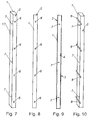
- Fig. 1 to 14 show preferred embodiments of a formwork connection device 1, wherein the formwork connection device 1 comprises a first coupling surface 2 and a second coupling surface 3 for coupling with compassionschatungsmaschinen 4.
- a formwork connection device 1 is used in particular for connecting two frame formwork elements 4, wherein a first frame formwork element 4 on the first coupling surface 2, and a second frame formwork element 4 on the second coupling surface 3 can be coupled.
- Frame formwork elements 4 are in particular straight and planar elements of a frame formwork system.
- Such frame formwork elements 4 may in particular have a flat formwork skin, which is preferably formed by a flat plate, which in particular already factory fixed to a frame, in particular welded or riveted, is.
- the formwork skin here refers to that surface which is intended to be in contact with the concrete and which defines the shape and surface structure of a concrete body.
- Frame formwork systems work on the modular principle and therefore have the advantage that they can be set up quickly and by a few people.
- Such frame formwork elements 4 may in particular be designed such that a plurality of mutually coupled frame formwork elements 4 form a flat formwork skin.
- the frame formwork elements 4 have, in particular, planar countercoupling surfaces 10 which are oriented normal to the surface of the formwork skin of the formwork elements 4.
- the negative feedback surfaces 10 of the frame formwork elements 4 are brought into surface contact, and connected to each other.
- first coupling surface 2 and / or the second coupling surface 3 may be planar, and / or preferably designed to be identical to a counter coupling surface 10 of a frame form element 4.
- the formwork connection device 1 comprises a formwork surface 5 adjoining the first coupling surface 2 and the second coupling surface 3.
- the formwork surface 5 forms in this case also in particular a part of the formwork skin and is preferably intended to come into direct contact with the concrete.
- the first coupling surface 2 and the shuttering surface 5, and / or the second coupling surface 3 with the shading surface 5 adjacent to form an edge so that in each case one end of the first coupling surface 2 and / or the second coupling surface 3 at one End of the formwork surface 5 abuts.
- first coupling surface 2 and the second coupling surface 3 enclose an angle ⁇ , and that the angle ⁇ is an acute angle.
- the angle ⁇ is the angle which the planes in which the first coupling surface 2 or the second coupling surface 3 are arranged enclose at the point of intersection. These planes may also be referred to as coupling surface planes 18.
- frame formwork elements 4 can be assembled to a substantially round formwork 12, whereby a structure of a formwork 12 is substantially simplified for a substantially round concrete body.
- the formwork connection device 1 itself forms part of the formwork, whereby it can be prevented that the still liquid concrete exits through the gap between two mutually pivoted frame formwork elements 4.
- a good stable connection with the usual for a frame formwork connection means 11 can be achieved.
- a trained formwork 12 can be reused well, in contrast to a round formwork, which is made only for a specific purpose.
- such a formwork 12 can be constructed quickly by untrained workers.
- the formwork connection device 1 is rigid, and the angle ⁇ is in particular a fixed angle, which is preferably predetermined during the production of the formwork connection device 1.
- the formwork connection device 1 is free of stresses, so it does not have to be stretched or bent in order to achieve the angle ⁇ , but this angle ⁇ is already predetermined.
- the formwork connection device 1 can be free of tensioning elements which predetermine the angle ⁇ by tensioning the formwork connection device 1 into the correct form by the tensioning elements.
- the formwork connection device 1 can generally consist essentially of any material that meets the static requirements, such as wood or plastic.
- the formwork connection device 1 can in particular be made of metal, in particular steel or aluminum. Show these materials particularly preferred mechanical properties.
- the formwork connection device 1 is designed as a profile carrier.
- a profile carrier has a cross section which is substantially constant over the length.
- the formwork connection device 1 can be particularly simple and easy to handle.
- the formwork connection device 1 is integrally formed.
- the formwork connection device 1 is formed as a hollow body.
- the formwork connection device 1 may comprise a formwork surface 5 opposite support wall 17.
- the formwork connection device 1 may be formed as a hollow profile. As a result, the formwork connection device 1 can be formed much more stable against twisting.
- the formwork connection device 1 is formed substantially free of cavities, so for example as a solid profile.
- substantially cavity-free means in the sense that the formwork connection device 1 is free from any voids except for any receptacles.
- the formwork connection device 1 is formed as an extruded profile.
- the formwork connection device 1 can be formed in a particularly simple manner with constant quality and constant angle ⁇ .
- the formwork connection device 1 can thereby be designed particularly simply as a hollow profile.
- the formwork connection device 1 is formed as a multi-angled plate.
- This plate may for example be preformed from a flat plate, or the formwork connection device 1 may be composed of a plurality of flat plates, in particular welded together, be.
- first coupling surface 2, and / or the second coupling surface 3 and / or the shuttering surface 5 are rectangular.
- the formwork connection device 1 in the region of the first coupling surface 2, and / or the second coupling surface 3 and / or the shuttering surface 5 has a thickness between 0.2 cm and 3 cm, in particular between 0.5 cm and 2 cm, having.
- the formwork connection device 1 has a height between 0.5 m and 6 m, in particular between 0.75 m and 3 m. Furthermore, it can be provided that the first coupling surface 2, and / or the second coupling surface 3 has a width between 2 cm and 50 cm, in particular between 2.5 cm and 20 cm.
- the shuttering surface 5 has a width between 3 cm and 150 cm.
- the shuttering surface 5 has a width between 3 cm and 25 cm, in particular between 4 cm and 15 cm.
- the formwork connection device 1 forms a squadron, which serves primarily to connect two frame formwork elements 4.
- the shuttering surface 5 has a width between 20 cm and 150 cm, in particular between 50 cm and 100 cm, has.
- the formwork connection device 1 can already form a significant part of formwork skin.
- the angle ⁇ is less than 30 °, in particular less than 20 °, particularly preferably less than 10 °.
- the angle ⁇ is greater than 1 °, especially greater than 2 °, is.
- the number of required formwork connection devices 1 can be kept low in an advantageous manner.
- angle ⁇ is a fraction of 360 ° by a natural number.
- formworks 12 can be formed by a plurality of similar formwork connection device 1, which have a closed and essentially round shape. In this case, it may in particular be provided that this natural number is greater than 10, in particular greater than 36, particularly preferably greater than 72.
- an angle between the first coupling surface 2 and the shuttering surface 5 is equal to an angle between the second coupling surface 3 and the shuttering surface 5.
- the shuttering connection device 1 is symmetrical. As a result, errors in the construction of the formwork 12 can be avoided, and the number of different forms of formwork connection device 1 are kept low.
- FIGS Fig. 1 to Fig. 6 The profiles of the first six preferred embodiments are in FIGS Fig. 1 to Fig. 6 shown, wherein in the Fig. 1 to Fig. 6 the finite wall thickness of the formwork connection device 1 is shown only as a dash.
- the first and the second preferred embodiment which in Fig. 1 and Fig. 2 are shown, have a trapezoidal closed hollow profile.
- the first preferred embodiment differs from the second preferred embodiment by the width of the shuttering surface 5, and in that the intersection of the coupling surface plane 18 of the first coupling surface 2 and the second coupling surface 3 in the first preferred embodiment intersect on a side facing the shuttering surface 5, while in the second preferred embodiment, the coupling surface plane 18 intersect at a side facing away from the shuttering surface 5.
- the third and fourth preferred embodiments in FIG. 3 and FIG. 4 are formed as an open hollow profile in contrast to the first and second preferred embodiment.
- the shuttering surface 5 is formed according to the first four preferred embodiments as a flat surface.
- the formwork connection device 1 has a simple and easy-to-manufacture profile.
- the shuttering surface 5 is formed in such a way, in particular by kinks and / or a curvature that the shuttering surface 5 at the first coupling surface 2 and / or the second coupling surface 3 is perpendicular.
- the tangent of the shuttering surface 5 in the contact region of the shuttering surface 5 and the frame formwork element 4 coincides with the plane of the shuttering skin of the frame shuttering element 4.
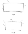
- the fifth and sixth preferred embodiments, which in FIGS. 5 and 6 is shown, has such a trained formwork surface 5 with two kinks.
- the concrete component produced by such a formwork 12 can have an advantageous shape because the edges are not in those locations where the first coupling surface 2 and / or the second coupling surface 3 were coupled to the negative-feedback surfaces 10.
- the shuttering surface 5 is perpendicular to the first coupling surface 2 and / or the second coupling surface 3, and that the shuttering surface 5 has a, in particular substantially uniform, curvature.
- first coupling surface 2 and / or the second coupling surface 3 have connection means receptacles 6.
- These connecting means receptacles 6 may be formed in particular as holes, openings or blind holes with or without thread.
- the formwork connection device 1 can be reliably coupled to frame formwork elements 4 which have similar connection means receptacles 6.
- the boundary extensions 8 protrude beyond the first coupling surface 2 and / or the second coupling surface 3, whereby the frame formwork elements 4 not through the hydrostatic pressure of the fresh concrete can be pushed away.
- the coupling of formwork connection device 1 and frame formwork elements 4 can also take place by formwork clamps, wherein the boundary extensions 8 can be used in particular as stops for the formwork clamps.
- the formwork connection device 1 has anchoring means receptacles 7.
- These anchoring means receptacles 7 may be formed in particular as an opening, particularly preferably as a bore through the formwork surface 5.
- two formwork walls 9 can be connected to such formwork connection device 1 by means of anchor rods 16.
- a shuttering wall 9 comprising at least one frame formwork element 4
- the at least one frame formwork element 4 comprises negative feedback surfaces 10
- the shuttering wall 9 comprises at least one formwork connection device 1 according to the advantageous manner described herein, and wherein one of the coupling surfaces 2,3 of the at least a formwork connection device 1, that is, the first coupling surface 2 or the second coupling surface 3, with a negative feedback surface 10 of the at least one frame formwork element 4 is connected.
- the shuttering wall 9 has a predeterminable plurality of identical formwork connection devices 1 and the same frame formwork elements 4, wherein preferably the number of formwork connection devices 1 and the frame formwork elements 4 is the same.
- a formwork wall 9 can be formed for substantially circular round structures, which consists essentially of two different elements, and is correspondingly easy to construct.
- the formwork wall 9 at least two differently shaped formwork connection device 1 and / or frame formwork elements 4 has.
- formwork connection device 1 with different angles ⁇ and an oval or substantially parabolic formwork wall 9 may be formed.
- a formwork connection device 1 of the first preferred embodiment and the second preferred embodiment in a shuttering wall 9 a wave-shaped shuttering wall 9 may be formed.
- frame formwork elements 4 of different lengths As a result, generally curved surfaces can be approximated in a simple manner by a combination of differently configured formwork connection devices 1 and / or frame formwork elements 4.
- the formwork wall 9 has the shape of a circle segment.
- the at least one formwork connection device 1 is releasably connected to the at least one frame formwork element 4 by means of connecting means 11.
- Such connecting means 11 may be formed in particular as a formwork clamp.
- the connecting means 11 is formed as a threaded rod 19.
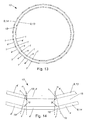
- Fig. 11 which represents a section through a connecting means 11, have the counter-coupling surfaces 10 of the frame formwork elements 4, and the first coupling surface 2 and the second coupling surface 3 holes through which the threaded rod 19 extends.
- the threaded rod 19 is clamped at its outer end, preferably by means of screw nuts 20, wherein the screw nuts 20 press the counter coupling surfaces 10 to the first coupling surface 2 and the second coupling surface 3.
- Washers 21 may still be provided.
- the threaded rod 19 is braced at one end only with a nut 20, wherein the other end is fixed by means of a wedge.
- the threaded rods 19, nuts 20 and washers 21 are for clarity in Fig. 12 not everywhere provided with reference numerals.
- a formwork 12 comprising an inner formwork wall 13 and an outer formwork wall 14 may be provided, wherein the inner formwork wall 13 and the outer formwork wall 14 are formed according to the preferred manner, wherein the first coupling surface 2 of a formwork connection device 1 of the inner formwork wall 13 with the first coupling surface 2 of a formwork connection device 1 of the outer formwork wall 14 is aligned, and wherein the second coupling surface 3 of the formwork connection device 1 of the inner formwork wall 13 with the second coupling surface 3 of the formwork connection device 1 of the outer formwork wall 14 is aligned.
- This alignment can be designed such that the first coupling surface 2 of a formwork connection device 1 of the inner formwork wall 13 and the first coupling surface 2 of a formwork connection device 1 of the outer formwork wall 14 are arranged within the same coupling surface plane 18.
- This can be formed with the same length frame formwork elements 4 a curvy concrete body with substantially the same thickness, the formwork 12 may be particularly simple for this concrete body.
- each coupling surface 2, 3 of the inner shuttering wall 13 is aligned with a coupling surface 2, 3 of the outer shuttering wall 14.
- the inner shuttering wall 13 and the outer shuttering wall 14 have frame formwork elements 4 of the same length.
- the inner shuttering wall 13 and an outer shuttering wall 14 define a space 15, and that the floor plan of the space 15 is an annular and substantially uniform polygon.
- This space 15 is limited in particular by the formwork skin of the formwork 12.
- This space 15 is in particular intended to be poured out with fresh concrete in order to form a substantially annular concrete component, in particular a wall.
- the cross-section of this space 15 remains constant over the entire height of the formwork 12 delimiting this space, that is to say that the space 15 is designed substantially as a hollow cylinder.
- This can be provided on a formwork for a substantially annular wall, which consists of a few different parts and can be easily constructed. Due to the simple construction of this formwork 12, this can also be easily constructed by less qualified personnel. Since only a small number of different types of parts need to be used, logistics can be greatly simplified.
- FIG. 2 shows a preferred embodiment of a formwork 12 comprising twenty-five formwork connection devices 1 of the first preferred embodiment, twenty-five formwork connection devices 1 of the second preferred embodiment, and fifty frame formwork elements 4.
- the angle ⁇ of the formwork connection devices 1 is 14.4 °.
- the formwork connection devices 1 of the first preferred embodiment are part of the outer formwork wall 14 and the formwork connection devices 1 of the second preferred embodiment are part of the inner formwork wall 13, wherein each two formwork connection devices 1 are connected by a frame formwork element 4.
- This preferred embodiment of a formwork 12 forms a formwork skin for a space 15 with an isosceles and equiangular twenty-five-cornered annular plan, the formwork connection devices 1 forming the corners of this plan.
- the number of formwork connection devices 1, and hence the corners of the floor plan is larger or smaller, thereby improving or worsening the similarity of the floor plan with a perfectly round body.
- the inner shuttering wall and the outer shuttering wall are connected by anchor means 16.
- the anchor means 16 may be formed in particular as anchor rods. As a result, the mechanical stability of the formwork 12 can be substantially increased.
- the anchoring means 16 is guided by the anchor means receptacles 7 of the formwork connection devices 1 of the inner formwork wall 13 and the outer formwork wall 14.
- the anchoring means formed as an anchor rod 16 may have threads at the ends, wherein the anchor means 16 is provided at one end with a nut plate 22, and at the other end by means of a wing nut 23 with washer 21 to clamp the opposite formwork connection devices 1 together.
Landscapes
- Engineering & Computer Science (AREA)
- Architecture (AREA)
- Mechanical Engineering (AREA)
- Civil Engineering (AREA)
- Structural Engineering (AREA)
- Forms Removed On Construction Sites Or Auxiliary Members Thereof (AREA)
Claims (13)
- Dispositif pour l'assemblage d'un coffrage (1), lequel dispositif pour l'assemblage d'un coffrage (1) comprend une première surface de couplage (2) et une deuxième surface de couplage (3) pour le couplage d'éléments de coffrage-cadre (4), lequel dispositif pour l'assemblage d'un coffrage (1) comprend une surface de coffre (5) limitrophe de la première surface de couplage (2) et de la deuxième surface de couplage (3), la première surface de couplage (2) et la deuxième surface de couplage (3) formant un angle α qui est inférieur à 30°, caractérisé en ce que le dispositif pour l'assemblage d'un coffrage (1) est conformé comme un profilé moulé par extrusion et en ce que l'angle α est une fraction de 360° par un nombre naturel.
- Dispositif pour l'assemblage d'un coffrage (1) selon la revendication 1, caractérisé en ce que le dispositif pour l'assemblage d'un coffrage (1) est conformé comme un corps creux.
- Dispositif pour l'assemblage d'un coffrage (1) selon la revendication 1 ou 2, caractérisé en ce que l'angle α est inférieur à 20°, de préférence inférieur à 10°.
- Dispositif pour l'assemblage d'un coffrage (1) selon l'une des revendications 1 à 3, caractérisé en ce qu'un angle entre la première surface de couplage (2) et la surface de coffre (5) est égal à un angle entre la deuxième surface de couplage (3) et la surface de coffre (5).
- Dispositif pour l'assemblage d'un coffrage (1) selon l'une des revendications 1 à 4, caractérisé en ce que la surface de coffre (5) est conformée comme une surface plane.
- Dispositif pour l'assemblage d'un coffrage (1) selon l'une des revendications 1 à 5, caractérisé en ce que la première surface de couplage (2) et/ou la deuxième surface de couplage (3) présentent des réceptacles pour des moyens d'assemblage (6).
- Dispositif pour l'assemblage d'un coffrage (1) selon l'une des revendications 1 à 6, caractérisé en ce qu'il est prévu sur une face du dispositif pour l'assemblage d'un coffrage (1) faisant face à la surface de coffre (5) des saillies de délimitation (8) pour le positionnement correct des éléments de coffrage-cadre (4).
- Dispositif pour l'assemblage d'un coffrage (1) selon l'une des revendications 1 à 7, caractérisé en ce que le dispositif pour l'assemblage d'un coffrage (1) présente des réceptacles (7) pour des moyens d'ancrage.
- Paroi de coffrage (9) comprenant au moins un élément de coffrage-cadre (4), dans laquelle l'au moins un élément de coffrage-cadre (4) comprend des contre-surfaces de couplage (10), caractérisée en ce que la paroi de coffrage (9) comprend au moins un dispositif pour l'assemblage d'un coffrage (1) selon l'une des revendications 1 à 8 et en ce que l'une des surfaces de couplage (2, 3) de l'au moins un dispositif pour l'assemblage d'un coffrage (1) est assemblée à une contre-surface de couplage (10) de l'au moins un élément de coffrage-cadre (4).
- Paroi de coffrage (9) selon la revendication 9, caractérisé en ce que l'au moins un dispositif pour l'assemblage d'un coffrage (1) est relié d'une manière pouvant être défaite à l'au moins un élément de coffrage-cadre (4) au moyen de moyens d'assemblage (11).
- Coffrage (12) comprenant une paroi de coffrage intérieure (13) et une paroi de coffrage extérieure (14), caractérisé en ce que la paroi de coffrage intérieure (13) et la paroi de coffrage extérieure (14) sont conformées selon la revendication 9 ou 10, en ce que la première surface de couplage (2) d'un dispositif pour l'assemblage d'un coffrage (1) de la paroi de coffrage intérieure (13) est alignée avec la première surface de couplage (2) d'un dispositif pour l'assemblage d'un coffrage (1) de la paroi de coffrage extérieure (14) et en ce que la deuxième surface de couplage (3) du dispositif pour l'assemblage d'un coffrage (1) de la paroi de coffrage intérieure (13) est alignée avec la deuxième surface de couplage (3) du dispositif pour l'assemblage d'un coffrage (1) de la paroi de coffrage extérieure (14).
- Coffrage (12) selon la revendication 11, caractérisé en ce que la paroi de coffrage intérieure (13) et une paroi de coffrage extérieure (14) délimitent un espace (15) et en ce que le plan de l'espace (15) est un polyèdre annulaire et sensiblement régulier.
- Coffrage selon la revendication 11 ou 12, caractérisé en ce que la paroi de coffrage intérieure et la paroi de coffrage extérieure sont reliées au moyen de moyen d'ancrage (16).
Applications Claiming Priority (2)
| Application Number | Priority Date | Filing Date | Title |
|---|---|---|---|
| AT5562012A AT512840B1 (de) | 2012-05-10 | 2012-05-10 | Schalungsverbindungsvorrichtung |
| PCT/AT2013/000087 WO2013166534A1 (fr) | 2012-05-10 | 2013-05-08 | Dispositif d'assemblage de coffrage |
Publications (2)
| Publication Number | Publication Date |
|---|---|
| EP2847397A1 EP2847397A1 (fr) | 2015-03-18 |
| EP2847397B1 true EP2847397B1 (fr) | 2016-07-13 |
Family
ID=48698821
Family Applications (1)
| Application Number | Title | Priority Date | Filing Date |
|---|---|---|---|
| EP13731250.0A Active EP2847397B1 (fr) | 2012-05-10 | 2013-05-08 | Dispositif d'assemblage de coffrage |
Country Status (3)
| Country | Link |
|---|---|
| EP (1) | EP2847397B1 (fr) |
| AT (1) | AT512840B1 (fr) |
| WO (1) | WO2013166534A1 (fr) |
Families Citing this family (1)
| Publication number | Priority date | Publication date | Assignee | Title |
|---|---|---|---|---|
| AT521553B1 (de) * | 2018-08-03 | 2023-02-15 | Sdo Zt Gmbh | Verfahren und Schalung zum Herstellen einer Platte, sowie Platte |
Family Cites Families (8)
| Publication number | Priority date | Publication date | Assignee | Title |
|---|---|---|---|---|
| DE2730542C2 (de) * | 1977-07-06 | 1982-06-09 | Streif AG, 5461 Vettelschoß | Schalungsfugen-Abdichtung |
| US4553729A (en) * | 1981-12-04 | 1985-11-19 | Symons Corporation | Multi-panelled concrete forming structure for forming flat curved walls |
| AT396277B (de) * | 1983-10-14 | 1993-07-26 | Rund Stahl Bau Gmbh & Co | Verfahren zur errichtung von aus gussfaehigen materialien insbesondere beton bestehenden baukoerpern und vorrichtungssystem zur durchfuehrung des verfahrens |
| DE8502232U1 (de) * | 1985-01-29 | 1986-07-24 | Hünnebeck GmbH, 4030 Ratingen | Schalungselement für Rundschalungen |
| DE3516536C1 (de) * | 1985-05-08 | 1986-07-31 | Josef 7611 Steinach Maier | Schalung für Rund- oder Vieleckbauten |
| US5044601A (en) * | 1989-05-30 | 1991-09-03 | Symons Corporation | Outside bay adapter for a concrete forming system |
| US6322046B1 (en) * | 1999-02-16 | 2001-11-27 | Michael R. Yurick | Form panel clamp |
| US20060156675A1 (en) * | 2000-09-19 | 2006-07-20 | Nelson Thomas P | Facer beam barrier system |
-
2012
- 2012-05-10 AT AT5562012A patent/AT512840B1/de not_active IP Right Cessation
-
2013
- 2013-05-08 EP EP13731250.0A patent/EP2847397B1/fr active Active
- 2013-05-08 WO PCT/AT2013/000087 patent/WO2013166534A1/fr not_active Ceased
Also Published As
| Publication number | Publication date |
|---|---|
| EP2847397A1 (fr) | 2015-03-18 |
| WO2013166534A1 (fr) | 2013-11-14 |
| AT512840B1 (de) | 2014-02-15 |
| AT512840A1 (de) | 2013-11-15 |
Similar Documents
| Publication | Publication Date | Title |
|---|---|---|
| EP2443352B1 (fr) | Système de liaison de barres profilées | |
| EP2786026A1 (fr) | Barre profilée, assemblage de profilés et procédé de fabrication d'un assemblage de profilés | |
| EP3536873A1 (fr) | Élément de profil ainsi que système de façade pourvu d'élément de profil | |
| EP3519641B1 (fr) | Dispositif de raccordement destiné à relier des éléments préfabriqués minces, éléments préfabriqués équipés de celui-ci, procédé de fabrication de tels éléments préfabriqués équipés d'un tel dispositif de raccordement | |
| EP0760886A1 (fr) | CONSTRUCTION DE FAçADE POUR BATIMENTS | |
| EP0250612A1 (fr) | Planche pour un échafaudage à érection rapide | |
| AT512840B1 (de) | Schalungsverbindungsvorrichtung | |
| EP2587185B1 (fr) | Moyens de connexion pouvant être connectés les uns aux autres par le profilé creux à l'aide d'au moins un écrou pour installations solaires, ainsi que système de profilé creux pour une installation solaire | |
| EP2816174B1 (fr) | Système de coffrage | |
| DE2741814A1 (de) | Bausatzeinheit | |
| DE2457523C2 (de) | Schalungszuganker mit abstandhalter fuer einander gegenueberstehende schalungswaende | |
| EP4375453B1 (fr) | Outil pour la finition et le lissage de joints | |
| EP3242983A1 (fr) | Element de coffrage de panneau de cadre | |
| CH709391A1 (de) | Befestigungsvorrichtung für Bauverschalungen, Befestigungsanordnung mit einer solchen und Verfahren zum Auf- und Abbau von Bauverschalungen. | |
| DE102006002910A1 (de) | Bauplatte zur Herstellung eines Eckelements | |
| DE1484181B2 (de) | Verfahren zum herstellen eines gitterartigen bewehrungselementes fuer betonbauteile und verbindungskoerper | |
| DE102018106675A1 (de) | Schalungselement | |
| DE1947923A1 (de) | Ringanker fuer Decken in Gebaeuden aus vorfabrizierten Bauelementen | |
| DE202024102899U1 (de) | Schalungssystem für Bauteile | |
| DE202021001827U1 (de) | Tiefenbegrenzer | |
| AT518533A4 (de) | Schalungselement zur Errichtung von Schallschutzwänden | |
| DE844057C (de) | Zusammensetzbare und zerlegbare Schalungen aus vorfabrizierten Elementen fuer den Betonbau | |
| DE102024130545A1 (de) | Abdichtsystem an Durchbrechungen in Formwerkzeugen oder Schalungen für die Fertigung von mit textilen Gebilden verstärkten vorgespannten Betonbauteilen | |
| DE10046407B4 (de) | Verfahren zur Herstellung eines Schalungselements aus Faserzement | |
| DE3307663A1 (de) | Bausatz zum errichten einer schalung |
Legal Events
| Date | Code | Title | Description |
|---|---|---|---|
| PUAI | Public reference made under article 153(3) epc to a published international application that has entered the european phase |
Free format text: ORIGINAL CODE: 0009012 |
|
| 17P | Request for examination filed |
Effective date: 20141210 |
|
| AK | Designated contracting states |
Kind code of ref document: A1 Designated state(s): AL AT BE BG CH CY CZ DE DK EE ES FI FR GB GR HR HU IE IS IT LI LT LU LV MC MK MT NL NO PL PT RO RS SE SI SK SM TR |
|
| AX | Request for extension of the european patent |
Extension state: BA ME |
|
| GRAP | Despatch of communication of intention to grant a patent |
Free format text: ORIGINAL CODE: EPIDOSNIGR1 |
|
| RIC1 | Information provided on ipc code assigned before grant |
Ipc: E04G 11/06 20060101AFI20151130BHEP Ipc: E04G 11/08 20060101ALI20151130BHEP |
|
| INTG | Intention to grant announced |
Effective date: 20151214 |
|
| GRAS | Grant fee paid |
Free format text: ORIGINAL CODE: EPIDOSNIGR3 |
|
| GRAA | (expected) grant |
Free format text: ORIGINAL CODE: 0009210 |
|
| AK | Designated contracting states |
Kind code of ref document: B1 Designated state(s): AL AT BE BG CH CY CZ DE DK EE ES FI FR GB GR HR HU IE IS IT LI LT LU LV MC MK MT NL NO PL PT RO RS SE SI SK SM TR |
|
| AX | Request for extension of the european patent |
Extension state: BA ME |
|
| REG | Reference to a national code |
Ref country code: GB Ref legal event code: FG4D Free format text: NOT ENGLISH |
|
| REG | Reference to a national code |
Ref country code: AT Ref legal event code: REF Ref document number: 812478 Country of ref document: AT Kind code of ref document: T Effective date: 20160715 Ref country code: CH Ref legal event code: EP |
|
| REG | Reference to a national code |
Ref country code: IE Ref legal event code: FG4D Free format text: LANGUAGE OF EP DOCUMENT: GERMAN |
|
| REG | Reference to a national code |
Ref country code: DE Ref legal event code: R096 Ref document number: 502013003732 Country of ref document: DE |
|
| REG | Reference to a national code |
Ref country code: CH Ref legal event code: NV Representative=s name: BOVARD AG, CH |
|
| REG | Reference to a national code |
Ref country code: LT Ref legal event code: MG4D |
|
| REG | Reference to a national code |
Ref country code: NL Ref legal event code: MP Effective date: 20160713 |
|
| PG25 | Lapsed in a contracting state [announced via postgrant information from national office to epo] |
Ref country code: FI Free format text: LAPSE BECAUSE OF FAILURE TO SUBMIT A TRANSLATION OF THE DESCRIPTION OR TO PAY THE FEE WITHIN THE PRESCRIBED TIME-LIMIT Effective date: 20160713 Ref country code: HR Free format text: LAPSE BECAUSE OF FAILURE TO SUBMIT A TRANSLATION OF THE DESCRIPTION OR TO PAY THE FEE WITHIN THE PRESCRIBED TIME-LIMIT Effective date: 20160713 Ref country code: RS Free format text: LAPSE BECAUSE OF FAILURE TO SUBMIT A TRANSLATION OF THE DESCRIPTION OR TO PAY THE FEE WITHIN THE PRESCRIBED TIME-LIMIT Effective date: 20160713 Ref country code: NO Free format text: LAPSE BECAUSE OF FAILURE TO SUBMIT A TRANSLATION OF THE DESCRIPTION OR TO PAY THE FEE WITHIN THE PRESCRIBED TIME-LIMIT Effective date: 20161013 Ref country code: IT Free format text: LAPSE BECAUSE OF FAILURE TO SUBMIT A TRANSLATION OF THE DESCRIPTION OR TO PAY THE FEE WITHIN THE PRESCRIBED TIME-LIMIT Effective date: 20160713 Ref country code: IS Free format text: LAPSE BECAUSE OF FAILURE TO SUBMIT A TRANSLATION OF THE DESCRIPTION OR TO PAY THE FEE WITHIN THE PRESCRIBED TIME-LIMIT Effective date: 20161113 Ref country code: LT Free format text: LAPSE BECAUSE OF FAILURE TO SUBMIT A TRANSLATION OF THE DESCRIPTION OR TO PAY THE FEE WITHIN THE PRESCRIBED TIME-LIMIT Effective date: 20160713 Ref country code: NL Free format text: LAPSE BECAUSE OF FAILURE TO SUBMIT A TRANSLATION OF THE DESCRIPTION OR TO PAY THE FEE WITHIN THE PRESCRIBED TIME-LIMIT Effective date: 20160713 |
|
| PG25 | Lapsed in a contracting state [announced via postgrant information from national office to epo] |
Ref country code: ES Free format text: LAPSE BECAUSE OF FAILURE TO SUBMIT A TRANSLATION OF THE DESCRIPTION OR TO PAY THE FEE WITHIN THE PRESCRIBED TIME-LIMIT Effective date: 20160713 Ref country code: PL Free format text: LAPSE BECAUSE OF FAILURE TO SUBMIT A TRANSLATION OF THE DESCRIPTION OR TO PAY THE FEE WITHIN THE PRESCRIBED TIME-LIMIT Effective date: 20160713 Ref country code: LV Free format text: LAPSE BECAUSE OF FAILURE TO SUBMIT A TRANSLATION OF THE DESCRIPTION OR TO PAY THE FEE WITHIN THE PRESCRIBED TIME-LIMIT Effective date: 20160713 Ref country code: GR Free format text: LAPSE BECAUSE OF FAILURE TO SUBMIT A TRANSLATION OF THE DESCRIPTION OR TO PAY THE FEE WITHIN THE PRESCRIBED TIME-LIMIT Effective date: 20161014 Ref country code: PT Free format text: LAPSE BECAUSE OF FAILURE TO SUBMIT A TRANSLATION OF THE DESCRIPTION OR TO PAY THE FEE WITHIN THE PRESCRIBED TIME-LIMIT Effective date: 20161114 Ref country code: SE Free format text: LAPSE BECAUSE OF FAILURE TO SUBMIT A TRANSLATION OF THE DESCRIPTION OR TO PAY THE FEE WITHIN THE PRESCRIBED TIME-LIMIT Effective date: 20160713 |
|
| REG | Reference to a national code |
Ref country code: DE Ref legal event code: R097 Ref document number: 502013003732 Country of ref document: DE |
|
| PG25 | Lapsed in a contracting state [announced via postgrant information from national office to epo] |
Ref country code: EE Free format text: LAPSE BECAUSE OF FAILURE TO SUBMIT A TRANSLATION OF THE DESCRIPTION OR TO PAY THE FEE WITHIN THE PRESCRIBED TIME-LIMIT Effective date: 20160713 Ref country code: RO Free format text: LAPSE BECAUSE OF FAILURE TO SUBMIT A TRANSLATION OF THE DESCRIPTION OR TO PAY THE FEE WITHIN THE PRESCRIBED TIME-LIMIT Effective date: 20160713 |
|
| PLBE | No opposition filed within time limit |
Free format text: ORIGINAL CODE: 0009261 |
|
| STAA | Information on the status of an ep patent application or granted ep patent |
Free format text: STATUS: NO OPPOSITION FILED WITHIN TIME LIMIT |
|
| REG | Reference to a national code |
Ref country code: FR Ref legal event code: PLFP Year of fee payment: 5 |
|
| PG25 | Lapsed in a contracting state [announced via postgrant information from national office to epo] |
Ref country code: BG Free format text: LAPSE BECAUSE OF FAILURE TO SUBMIT A TRANSLATION OF THE DESCRIPTION OR TO PAY THE FEE WITHIN THE PRESCRIBED TIME-LIMIT Effective date: 20161013 Ref country code: SK Free format text: LAPSE BECAUSE OF FAILURE TO SUBMIT A TRANSLATION OF THE DESCRIPTION OR TO PAY THE FEE WITHIN THE PRESCRIBED TIME-LIMIT Effective date: 20160713 Ref country code: CZ Free format text: LAPSE BECAUSE OF FAILURE TO SUBMIT A TRANSLATION OF THE DESCRIPTION OR TO PAY THE FEE WITHIN THE PRESCRIBED TIME-LIMIT Effective date: 20160713 Ref country code: DK Free format text: LAPSE BECAUSE OF FAILURE TO SUBMIT A TRANSLATION OF THE DESCRIPTION OR TO PAY THE FEE WITHIN THE PRESCRIBED TIME-LIMIT Effective date: 20160713 Ref country code: SM Free format text: LAPSE BECAUSE OF FAILURE TO SUBMIT A TRANSLATION OF THE DESCRIPTION OR TO PAY THE FEE WITHIN THE PRESCRIBED TIME-LIMIT Effective date: 20160713 |
|
| 26N | No opposition filed |
Effective date: 20170418 |
|
| PG25 | Lapsed in a contracting state [announced via postgrant information from national office to epo] |
Ref country code: SI Free format text: LAPSE BECAUSE OF FAILURE TO SUBMIT A TRANSLATION OF THE DESCRIPTION OR TO PAY THE FEE WITHIN THE PRESCRIBED TIME-LIMIT Effective date: 20160713 Ref country code: LU Free format text: LAPSE BECAUSE OF NON-PAYMENT OF DUE FEES Effective date: 20170531 |
|
| GBPC | Gb: european patent ceased through non-payment of renewal fee |
Effective date: 20170508 |
|
| PG25 | Lapsed in a contracting state [announced via postgrant information from national office to epo] |
Ref country code: MC Free format text: LAPSE BECAUSE OF FAILURE TO SUBMIT A TRANSLATION OF THE DESCRIPTION OR TO PAY THE FEE WITHIN THE PRESCRIBED TIME-LIMIT Effective date: 20160713 |
|
| REG | Reference to a national code |
Ref country code: IE Ref legal event code: MM4A |
|
| PG25 | Lapsed in a contracting state [announced via postgrant information from national office to epo] |
Ref country code: LU Free format text: LAPSE BECAUSE OF NON-PAYMENT OF DUE FEES Effective date: 20170508 |
|
| REG | Reference to a national code |
Ref country code: BE Ref legal event code: MM Effective date: 20170531 |
|
| PG25 | Lapsed in a contracting state [announced via postgrant information from national office to epo] |
Ref country code: IE Free format text: LAPSE BECAUSE OF NON-PAYMENT OF DUE FEES Effective date: 20170508 Ref country code: GB Free format text: LAPSE BECAUSE OF NON-PAYMENT OF DUE FEES Effective date: 20170508 |
|
| REG | Reference to a national code |
Ref country code: FR Ref legal event code: PLFP Year of fee payment: 6 |
|
| PG25 | Lapsed in a contracting state [announced via postgrant information from national office to epo] |
Ref country code: BE Free format text: LAPSE BECAUSE OF NON-PAYMENT OF DUE FEES Effective date: 20170531 |
|
| PG25 | Lapsed in a contracting state [announced via postgrant information from national office to epo] |
Ref country code: MT Free format text: LAPSE BECAUSE OF FAILURE TO SUBMIT A TRANSLATION OF THE DESCRIPTION OR TO PAY THE FEE WITHIN THE PRESCRIBED TIME-LIMIT Effective date: 20160713 |
|
| PG25 | Lapsed in a contracting state [announced via postgrant information from national office to epo] |
Ref country code: AL Free format text: LAPSE BECAUSE OF FAILURE TO SUBMIT A TRANSLATION OF THE DESCRIPTION OR TO PAY THE FEE WITHIN THE PRESCRIBED TIME-LIMIT Effective date: 20160713 |
|
| PG25 | Lapsed in a contracting state [announced via postgrant information from national office to epo] |
Ref country code: HU Free format text: LAPSE BECAUSE OF FAILURE TO SUBMIT A TRANSLATION OF THE DESCRIPTION OR TO PAY THE FEE WITHIN THE PRESCRIBED TIME-LIMIT; INVALID AB INITIO Effective date: 20130508 |
|
| PG25 | Lapsed in a contracting state [announced via postgrant information from national office to epo] |
Ref country code: CY Free format text: LAPSE BECAUSE OF FAILURE TO SUBMIT A TRANSLATION OF THE DESCRIPTION OR TO PAY THE FEE WITHIN THE PRESCRIBED TIME-LIMIT Effective date: 20160713 |
|
| PG25 | Lapsed in a contracting state [announced via postgrant information from national office to epo] |
Ref country code: MK Free format text: LAPSE BECAUSE OF FAILURE TO SUBMIT A TRANSLATION OF THE DESCRIPTION OR TO PAY THE FEE WITHIN THE PRESCRIBED TIME-LIMIT Effective date: 20160713 |
|
| PG25 | Lapsed in a contracting state [announced via postgrant information from national office to epo] |
Ref country code: TR Free format text: LAPSE BECAUSE OF FAILURE TO SUBMIT A TRANSLATION OF THE DESCRIPTION OR TO PAY THE FEE WITHIN THE PRESCRIBED TIME-LIMIT Effective date: 20160713 |
|
| P01 | Opt-out of the competence of the unified patent court (upc) registered |
Effective date: 20230521 |
|
| PGFP | Annual fee paid to national office [announced via postgrant information from national office to epo] |
Ref country code: DE Payment date: 20250519 Year of fee payment: 13 |
|
| PGFP | Annual fee paid to national office [announced via postgrant information from national office to epo] |
Ref country code: FR Payment date: 20250523 Year of fee payment: 13 |
|
| PGFP | Annual fee paid to national office [announced via postgrant information from national office to epo] |
Ref country code: CH Payment date: 20250601 Year of fee payment: 13 |
|
| PGFP | Annual fee paid to national office [announced via postgrant information from national office to epo] |
Ref country code: AT Payment date: 20250429 Year of fee payment: 13 |