EP2847397B1 - Formwork connecting device - Google Patents
Formwork connecting device Download PDFInfo
- Publication number
- EP2847397B1 EP2847397B1 EP13731250.0A EP13731250A EP2847397B1 EP 2847397 B1 EP2847397 B1 EP 2847397B1 EP 13731250 A EP13731250 A EP 13731250A EP 2847397 B1 EP2847397 B1 EP 2847397B1
- Authority
- EP
- European Patent Office
- Prior art keywords
- formwork
- coupling surface
- wall
- connecting apparatus
- connection device
- Prior art date
- Legal status (The legal status is an assumption and is not a legal conclusion. Google has not performed a legal analysis and makes no representation as to the accuracy of the status listed.)
- Active
Links
Images


Classifications
-
- E—FIXED CONSTRUCTIONS
- E04—BUILDING
- E04G—SCAFFOLDING; FORMS; SHUTTERING; BUILDING IMPLEMENTS OR AIDS, OR THEIR USE; HANDLING BUILDING MATERIALS ON THE SITE; REPAIRING, BREAKING-UP OR OTHER WORK ON EXISTING BUILDINGS
- E04G11/00—Forms, shutterings, or falsework for making walls, floors, ceilings, or roofs
- E04G11/06—Forms, shutterings, or falsework for making walls, floors, ceilings, or roofs for walls, e.g. curved end panels for wall shutterings; filler elements for wall shutterings; shutterings for vertical ducts
- E04G11/062—Forms for curved walls
-
- E—FIXED CONSTRUCTIONS
- E04—BUILDING
- E04G—SCAFFOLDING; FORMS; SHUTTERING; BUILDING IMPLEMENTS OR AIDS, OR THEIR USE; HANDLING BUILDING MATERIALS ON THE SITE; REPAIRING, BREAKING-UP OR OTHER WORK ON EXISTING BUILDINGS
- E04G11/00—Forms, shutterings, or falsework for making walls, floors, ceilings, or roofs
- E04G11/06—Forms, shutterings, or falsework for making walls, floors, ceilings, or roofs for walls, e.g. curved end panels for wall shutterings; filler elements for wall shutterings; shutterings for vertical ducts
- E04G11/08—Forms, which are completely dismantled after setting of the concrete and re-built for next pouring
- E04G11/087—Fill-in form panels in the plane of two adjacent forms
Definitions
- the invention relates to a formwork connection device according to the preamble of claim 1.
- a formwork is a mold in which, for example, fresh concrete can be introduced to specify the shape of a concrete body. It is a widely used technique that can be designed in many different ways.
- a special challenge for the formwork technology are round constructions, ie buildings which are essentially round, for example circular. Such structures can be for example silos, basins or round pillars.
- a complex formwork must be constructed, which consists for example of flexible shuttering panels, which are brought by a suitable rear triangle in the right shape.
- the object of the invention is therefore to provide a formwork connection device of the type mentioned above, with which the mentioned disadvantages can be avoided, with which a formwork for round buildings can be provided in a simple manner.
- frame formwork elements can be assembled to a substantially round formwork, whereby a structure of a formwork for a substantially round concrete body is substantially simplified.
- the formwork connection device itself forms part of the formwork skin, whereby it can be prevented that the still liquid concrete emerges through the gap between two mutually pivoted frame formwork elements.
- Fig. 1 to 14 show preferred embodiments of a formwork connection device 1, wherein the formwork connection device 1 comprises a first coupling surface 2 and a second coupling surface 3 for coupling with compassionschatungsmaschinen 4.
- a formwork connection device 1 is used in particular for connecting two frame formwork elements 4, wherein a first frame formwork element 4 on the first coupling surface 2, and a second frame formwork element 4 on the second coupling surface 3 can be coupled.
- Frame formwork elements 4 are in particular straight and planar elements of a frame formwork system.
- Such frame formwork elements 4 may in particular have a flat formwork skin, which is preferably formed by a flat plate, which in particular already factory fixed to a frame, in particular welded or riveted, is.
- the formwork skin here refers to that surface which is intended to be in contact with the concrete and which defines the shape and surface structure of a concrete body.
- Frame formwork systems work on the modular principle and therefore have the advantage that they can be set up quickly and by a few people.
- Such frame formwork elements 4 may in particular be designed such that a plurality of mutually coupled frame formwork elements 4 form a flat formwork skin.
- the frame formwork elements 4 have, in particular, planar countercoupling surfaces 10 which are oriented normal to the surface of the formwork skin of the formwork elements 4.
- the negative feedback surfaces 10 of the frame formwork elements 4 are brought into surface contact, and connected to each other.
- first coupling surface 2 and / or the second coupling surface 3 may be planar, and / or preferably designed to be identical to a counter coupling surface 10 of a frame form element 4.
- the formwork connection device 1 comprises a formwork surface 5 adjoining the first coupling surface 2 and the second coupling surface 3.
- the formwork surface 5 forms in this case also in particular a part of the formwork skin and is preferably intended to come into direct contact with the concrete.
- the first coupling surface 2 and the shuttering surface 5, and / or the second coupling surface 3 with the shading surface 5 adjacent to form an edge so that in each case one end of the first coupling surface 2 and / or the second coupling surface 3 at one End of the formwork surface 5 abuts.
- first coupling surface 2 and the second coupling surface 3 enclose an angle ⁇ , and that the angle ⁇ is an acute angle.
- the angle ⁇ is the angle which the planes in which the first coupling surface 2 or the second coupling surface 3 are arranged enclose at the point of intersection. These planes may also be referred to as coupling surface planes 18.
- frame formwork elements 4 can be assembled to a substantially round formwork 12, whereby a structure of a formwork 12 is substantially simplified for a substantially round concrete body.
- the formwork connection device 1 itself forms part of the formwork, whereby it can be prevented that the still liquid concrete exits through the gap between two mutually pivoted frame formwork elements 4.
- a good stable connection with the usual for a frame formwork connection means 11 can be achieved.
- a trained formwork 12 can be reused well, in contrast to a round formwork, which is made only for a specific purpose.
- such a formwork 12 can be constructed quickly by untrained workers.
- the formwork connection device 1 is rigid, and the angle ⁇ is in particular a fixed angle, which is preferably predetermined during the production of the formwork connection device 1.
- the formwork connection device 1 is free of stresses, so it does not have to be stretched or bent in order to achieve the angle ⁇ , but this angle ⁇ is already predetermined.
- the formwork connection device 1 can be free of tensioning elements which predetermine the angle ⁇ by tensioning the formwork connection device 1 into the correct form by the tensioning elements.
- the formwork connection device 1 can generally consist essentially of any material that meets the static requirements, such as wood or plastic.
- the formwork connection device 1 can in particular be made of metal, in particular steel or aluminum. Show these materials particularly preferred mechanical properties.
- the formwork connection device 1 is designed as a profile carrier.
- a profile carrier has a cross section which is substantially constant over the length.
- the formwork connection device 1 can be particularly simple and easy to handle.
- the formwork connection device 1 is integrally formed.
- the formwork connection device 1 is formed as a hollow body.
- the formwork connection device 1 may comprise a formwork surface 5 opposite support wall 17.
- the formwork connection device 1 may be formed as a hollow profile. As a result, the formwork connection device 1 can be formed much more stable against twisting.
- the formwork connection device 1 is formed substantially free of cavities, so for example as a solid profile.
- substantially cavity-free means in the sense that the formwork connection device 1 is free from any voids except for any receptacles.
- the formwork connection device 1 is formed as an extruded profile.
- the formwork connection device 1 can be formed in a particularly simple manner with constant quality and constant angle ⁇ .
- the formwork connection device 1 can thereby be designed particularly simply as a hollow profile.
- the formwork connection device 1 is formed as a multi-angled plate.
- This plate may for example be preformed from a flat plate, or the formwork connection device 1 may be composed of a plurality of flat plates, in particular welded together, be.
- first coupling surface 2, and / or the second coupling surface 3 and / or the shuttering surface 5 are rectangular.
- the formwork connection device 1 in the region of the first coupling surface 2, and / or the second coupling surface 3 and / or the shuttering surface 5 has a thickness between 0.2 cm and 3 cm, in particular between 0.5 cm and 2 cm, having.
- the formwork connection device 1 has a height between 0.5 m and 6 m, in particular between 0.75 m and 3 m. Furthermore, it can be provided that the first coupling surface 2, and / or the second coupling surface 3 has a width between 2 cm and 50 cm, in particular between 2.5 cm and 20 cm.
- the shuttering surface 5 has a width between 3 cm and 150 cm.
- the shuttering surface 5 has a width between 3 cm and 25 cm, in particular between 4 cm and 15 cm.
- the formwork connection device 1 forms a squadron, which serves primarily to connect two frame formwork elements 4.
- the shuttering surface 5 has a width between 20 cm and 150 cm, in particular between 50 cm and 100 cm, has.
- the formwork connection device 1 can already form a significant part of formwork skin.
- the angle ⁇ is less than 30 °, in particular less than 20 °, particularly preferably less than 10 °.
- the angle ⁇ is greater than 1 °, especially greater than 2 °, is.
- the number of required formwork connection devices 1 can be kept low in an advantageous manner.
- angle ⁇ is a fraction of 360 ° by a natural number.
- formworks 12 can be formed by a plurality of similar formwork connection device 1, which have a closed and essentially round shape. In this case, it may in particular be provided that this natural number is greater than 10, in particular greater than 36, particularly preferably greater than 72.
- an angle between the first coupling surface 2 and the shuttering surface 5 is equal to an angle between the second coupling surface 3 and the shuttering surface 5.
- the shuttering connection device 1 is symmetrical. As a result, errors in the construction of the formwork 12 can be avoided, and the number of different forms of formwork connection device 1 are kept low.
- FIGS Fig. 1 to Fig. 6 The profiles of the first six preferred embodiments are in FIGS Fig. 1 to Fig. 6 shown, wherein in the Fig. 1 to Fig. 6 the finite wall thickness of the formwork connection device 1 is shown only as a dash.
- the first and the second preferred embodiment which in Fig. 1 and Fig. 2 are shown, have a trapezoidal closed hollow profile.
- the first preferred embodiment differs from the second preferred embodiment by the width of the shuttering surface 5, and in that the intersection of the coupling surface plane 18 of the first coupling surface 2 and the second coupling surface 3 in the first preferred embodiment intersect on a side facing the shuttering surface 5, while in the second preferred embodiment, the coupling surface plane 18 intersect at a side facing away from the shuttering surface 5.
- the third and fourth preferred embodiments in FIG. 3 and FIG. 4 are formed as an open hollow profile in contrast to the first and second preferred embodiment.
- the shuttering surface 5 is formed according to the first four preferred embodiments as a flat surface.
- the formwork connection device 1 has a simple and easy-to-manufacture profile.
- the shuttering surface 5 is formed in such a way, in particular by kinks and / or a curvature that the shuttering surface 5 at the first coupling surface 2 and / or the second coupling surface 3 is perpendicular.
- the tangent of the shuttering surface 5 in the contact region of the shuttering surface 5 and the frame formwork element 4 coincides with the plane of the shuttering skin of the frame shuttering element 4.
- the fifth and sixth preferred embodiments, which in FIGS. 5 and 6 is shown, has such a trained formwork surface 5 with two kinks.
- the concrete component produced by such a formwork 12 can have an advantageous shape because the edges are not in those locations where the first coupling surface 2 and / or the second coupling surface 3 were coupled to the negative-feedback surfaces 10.
- the shuttering surface 5 is perpendicular to the first coupling surface 2 and / or the second coupling surface 3, and that the shuttering surface 5 has a, in particular substantially uniform, curvature.
- first coupling surface 2 and / or the second coupling surface 3 have connection means receptacles 6.
- These connecting means receptacles 6 may be formed in particular as holes, openings or blind holes with or without thread.
- the formwork connection device 1 can be reliably coupled to frame formwork elements 4 which have similar connection means receptacles 6.
- the boundary extensions 8 protrude beyond the first coupling surface 2 and / or the second coupling surface 3, whereby the frame formwork elements 4 not through the hydrostatic pressure of the fresh concrete can be pushed away.
- the coupling of formwork connection device 1 and frame formwork elements 4 can also take place by formwork clamps, wherein the boundary extensions 8 can be used in particular as stops for the formwork clamps.
- the formwork connection device 1 has anchoring means receptacles 7.
- These anchoring means receptacles 7 may be formed in particular as an opening, particularly preferably as a bore through the formwork surface 5.
- two formwork walls 9 can be connected to such formwork connection device 1 by means of anchor rods 16.
- a shuttering wall 9 comprising at least one frame formwork element 4
- the at least one frame formwork element 4 comprises negative feedback surfaces 10
- the shuttering wall 9 comprises at least one formwork connection device 1 according to the advantageous manner described herein, and wherein one of the coupling surfaces 2,3 of the at least a formwork connection device 1, that is, the first coupling surface 2 or the second coupling surface 3, with a negative feedback surface 10 of the at least one frame formwork element 4 is connected.
- the shuttering wall 9 has a predeterminable plurality of identical formwork connection devices 1 and the same frame formwork elements 4, wherein preferably the number of formwork connection devices 1 and the frame formwork elements 4 is the same.
- a formwork wall 9 can be formed for substantially circular round structures, which consists essentially of two different elements, and is correspondingly easy to construct.
- the formwork wall 9 at least two differently shaped formwork connection device 1 and / or frame formwork elements 4 has.
- formwork connection device 1 with different angles ⁇ and an oval or substantially parabolic formwork wall 9 may be formed.
- a formwork connection device 1 of the first preferred embodiment and the second preferred embodiment in a shuttering wall 9 a wave-shaped shuttering wall 9 may be formed.
- frame formwork elements 4 of different lengths As a result, generally curved surfaces can be approximated in a simple manner by a combination of differently configured formwork connection devices 1 and / or frame formwork elements 4.
- the formwork wall 9 has the shape of a circle segment.
- the at least one formwork connection device 1 is releasably connected to the at least one frame formwork element 4 by means of connecting means 11.
- Such connecting means 11 may be formed in particular as a formwork clamp.
- the connecting means 11 is formed as a threaded rod 19.
- Fig. 11 which represents a section through a connecting means 11, have the counter-coupling surfaces 10 of the frame formwork elements 4, and the first coupling surface 2 and the second coupling surface 3 holes through which the threaded rod 19 extends.
- the threaded rod 19 is clamped at its outer end, preferably by means of screw nuts 20, wherein the screw nuts 20 press the counter coupling surfaces 10 to the first coupling surface 2 and the second coupling surface 3.
- Washers 21 may still be provided.
- the threaded rod 19 is braced at one end only with a nut 20, wherein the other end is fixed by means of a wedge.
- the threaded rods 19, nuts 20 and washers 21 are for clarity in Fig. 12 not everywhere provided with reference numerals.
- a formwork 12 comprising an inner formwork wall 13 and an outer formwork wall 14 may be provided, wherein the inner formwork wall 13 and the outer formwork wall 14 are formed according to the preferred manner, wherein the first coupling surface 2 of a formwork connection device 1 of the inner formwork wall 13 with the first coupling surface 2 of a formwork connection device 1 of the outer formwork wall 14 is aligned, and wherein the second coupling surface 3 of the formwork connection device 1 of the inner formwork wall 13 with the second coupling surface 3 of the formwork connection device 1 of the outer formwork wall 14 is aligned.
- This alignment can be designed such that the first coupling surface 2 of a formwork connection device 1 of the inner formwork wall 13 and the first coupling surface 2 of a formwork connection device 1 of the outer formwork wall 14 are arranged within the same coupling surface plane 18.
- This can be formed with the same length frame formwork elements 4 a curvy concrete body with substantially the same thickness, the formwork 12 may be particularly simple for this concrete body.
- each coupling surface 2, 3 of the inner shuttering wall 13 is aligned with a coupling surface 2, 3 of the outer shuttering wall 14.
- the inner shuttering wall 13 and the outer shuttering wall 14 have frame formwork elements 4 of the same length.
- the inner shuttering wall 13 and an outer shuttering wall 14 define a space 15, and that the floor plan of the space 15 is an annular and substantially uniform polygon.
- This space 15 is limited in particular by the formwork skin of the formwork 12.
- This space 15 is in particular intended to be poured out with fresh concrete in order to form a substantially annular concrete component, in particular a wall.
- the cross-section of this space 15 remains constant over the entire height of the formwork 12 delimiting this space, that is to say that the space 15 is designed substantially as a hollow cylinder.
- This can be provided on a formwork for a substantially annular wall, which consists of a few different parts and can be easily constructed. Due to the simple construction of this formwork 12, this can also be easily constructed by less qualified personnel. Since only a small number of different types of parts need to be used, logistics can be greatly simplified.
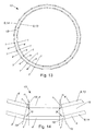
- FIG. 2 shows a preferred embodiment of a formwork 12 comprising twenty-five formwork connection devices 1 of the first preferred embodiment, twenty-five formwork connection devices 1 of the second preferred embodiment, and fifty frame formwork elements 4.
- the angle ⁇ of the formwork connection devices 1 is 14.4 °.
- the formwork connection devices 1 of the first preferred embodiment are part of the outer formwork wall 14 and the formwork connection devices 1 of the second preferred embodiment are part of the inner formwork wall 13, wherein each two formwork connection devices 1 are connected by a frame formwork element 4.
- This preferred embodiment of a formwork 12 forms a formwork skin for a space 15 with an isosceles and equiangular twenty-five-cornered annular plan, the formwork connection devices 1 forming the corners of this plan.
- the number of formwork connection devices 1, and hence the corners of the floor plan is larger or smaller, thereby improving or worsening the similarity of the floor plan with a perfectly round body.
- the inner shuttering wall and the outer shuttering wall are connected by anchor means 16.
- the anchor means 16 may be formed in particular as anchor rods. As a result, the mechanical stability of the formwork 12 can be substantially increased.
- the anchoring means 16 is guided by the anchor means receptacles 7 of the formwork connection devices 1 of the inner formwork wall 13 and the outer formwork wall 14.
- the anchoring means formed as an anchor rod 16 may have threads at the ends, wherein the anchor means 16 is provided at one end with a nut plate 22, and at the other end by means of a wing nut 23 with washer 21 to clamp the opposite formwork connection devices 1 together.
Landscapes
- Engineering & Computer Science (AREA)
- Architecture (AREA)
- Mechanical Engineering (AREA)
- Civil Engineering (AREA)
- Structural Engineering (AREA)
- Forms Removed On Construction Sites Or Auxiliary Members Thereof (AREA)
Description
Die Erfindung betrifft eine Schalungsverbindungsvorrichtung gemäß dem Oberbegriff des Patentanspruches 1.The invention relates to a formwork connection device according to the preamble of
Eine Schalung ist eine Gussform in welche beispielsweise Frischbeton eingebracht werden kann, um die Form eines Betonkörpers vorzugeben. Es handelt sich hierbei um eine weit verbreitete Technik, welche auf viele verschiedene Arten ausgebildet sein kann.A formwork is a mold in which, for example, fresh concrete can be introduced to specify the shape of a concrete body. It is a widely used technique that can be designed in many different ways.
Eine besondere Herausforderung für die Schalungstechnik sind Rundbauten, also Bauten die im Wesentlichen rund, beispielsweise kreisförmig, ausgebildet sind. Solche Bauten können beispielsweise Silos, Becken oder runde Pfeiler sein. Für solche Bauten muss eine aufwendige Schalung konstruiert werden, welche beispielsweise aus flexiblen Schalungsplatten besteht, welche durch einen geeigneten Hinterbau in die richtige Form gebracht werden.A special challenge for the formwork technology are round constructions, ie buildings which are essentially round, for example circular. Such structures can be for example silos, basins or round pillars. For such buildings a complex formwork must be constructed, which consists for example of flexible shuttering panels, which are brought by a suitable rear triangle in the right shape.
Aus der
Aus der
Aus der
Aus der
Aus der
Aus der
Aus der
Nachteilig daran ist dass eine derartige Schalung nur mit einem hohen Zeitaufwand konstruiert werden kann, wobei die Konstruktion der Schalung auf die spezielle Anwendung und Form hin ausgelegt werden muss. Eine derartige Schalung ist oft nicht wiederverwertbar und teuer, da qualifiziertes Fachpersonal erforderlich ist.The disadvantage of this is that such a formwork can be constructed only with a great deal of time, the design of the formwork must be designed for the specific application and shape. Such a formwork is often not recyclable and expensive, since qualified specialist personnel is required.
Aufgabe der Erfindung ist es daher eine Schalungsverbindungsvorrichtung der eingangs genannten Art anzugeben, mit welcher die genannten Nachteile vermieden werden können, mit welcher eine Schalung für Rundbauten auf einfache Weise zur Verfügung gestellt werden kann.The object of the invention is therefore to provide a formwork connection device of the type mentioned above, with which the mentioned disadvantages can be avoided, with which a formwork for round buildings can be provided in a simple manner.
Erfindungsgemäß wird dies durch die Merkmale des Patentanspruches 1 erreicht.This is achieved by the features of
Dadurch ergibt sich der Vorteil, dass Rahmenschalungselemente zu einer im Wesentlichen runden Schalung zusammengefügt werden können, wodurch ein Aufbau einer Schalung für einen im Wesentlichen runden Betonkörper wesentlich vereinfacht wird. Hierbei bildet die Schalungsverbindungsvorrichtung selber einen Teil der Schalhaut, wodurch verhindert werden kann, dass der noch flüssige Beton durch den Spalt zwischen zwei zueinander verschwenkten Rahmenschalungselementen austritt. Durch die Verbindung mit den Rahmenschalungselementen durch die erste Kopplungsfläche und die zweite Kopplungsfläche kann eine gute stabile Verbindung mit den für eine Rahmenschalung üblichen Verbindungsmitteln erreicht werden. Weiters kann eine derart ausgebildete Schalung gut wiederverwendet werden, im Gegensatz zu einer runden Schalung, welche lediglich für einen bestimmten Einsatzzweck gefertigt wird. Weiters kann eine derartige Schalung schnell von ungeschulten Arbeitern aufgebaut werden.This results in the advantage that frame formwork elements can be assembled to a substantially round formwork, whereby a structure of a formwork for a substantially round concrete body is substantially simplified. Here, the formwork connection device itself forms part of the formwork skin, whereby it can be prevented that the still liquid concrete emerges through the gap between two mutually pivoted frame formwork elements. By connecting with the Frame formwork elements through the first coupling surface and the second coupling surface, a good stable connection can be achieved with the usual formwork for a formwork connection means. Furthermore, such a formwork can be well reused, in contrast to a round formwork, which is made only for a specific purpose. Furthermore, such a formwork can be quickly built by untrained workers.
Die Unteransprüche betreffen weitere vorteilhafte Ausgestaltungen der Erfindung.The subclaims relate to further advantageous embodiments of the invention.
Ausdrücklich wird hiermit auf den Wortlaut der Patentansprüche Bezug genommen, wodurch die Ansprüche an dieser Stelle durch Bezugnahme in die Beschreibung eingefügt sind und als wörtlich wiedergegeben gelten.It is hereby expressly referred to the wording of the claims, whereby the claims at this point are incorporated by reference into the description and are considered to be reproduced verbatim.
Die Erfindung wird unter Bezugnahme auf die beigeschlossenen Zeichnungen, in welchen lediglich bevorzugte Ausführungsformen beispielhaft dargestellt sind, näher beschrieben. Dabei zeigt:
-
Fig. 1 das Profil einer ersten bevorzugten Ausführungsform der Schatungsverbindungsvorrichtung; -
Fig. 2 das Profil einer zweiten bevorzugten Ausführungsform der Schalungsverbindungsvorrichtung; -
Fig. 3 das Profil einer dritten bevorzugten Ausführungsform der Schalungsverbindungsvorrichtung; -
Fig. 4 das Profil einer vierten bevorzugten Ausführungsform der Schalungsverbindungsvorrichtung; -
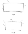
Fig. 5 das Profil einer fünften bevorzugten Ausführungsform der Schalungsverbindungsvorrichtung; -
Fig. 6 das Profil einer sechsten bevorzugten Ausführungsform der Schatungsverbindungsvorrichtung; -
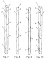
Fig. 7 die erste bevorzugte Ausführungsform der Schalungsverbindungsvorrichtung; -
Fig. 8 die erste bevorzugte Ausführungsform der Schalungsverbindungsvorrichtung in Seitenansicht; -
Fig. 9 die erste bevorzugte Ausführungsform der Schalungsverbindungsvorrichtung in Vorderansicht; -
Fig. 10 eine siebente bevorzugte Ausführungsform der - Schalungsverbindungsvorrichtung;
-
Fig. 11 ein Detail einer bevorzugten Ausführungsform einer Schalung aus der Sicht von oben; -
Fig. 12 ein Schnitt gemäß der Linie A ausFig. 11 ; -
Fig. 13 die bevorzugte Ausführungsform einer Schalung aus der Sicht von oben; und -
Fig. 14 ein Detail der bevorzugten Ausführungsform einer Schalung aus der Sicht von oben;
-
Fig. 1 the profile of a first preferred embodiment of the Schatungsverbindungsvorrichtung; -
Fig. 2 the profile of a second preferred embodiment of the formwork connection device; -
Fig. 3 the profile of a third preferred embodiment of the formwork connection device; -
Fig. 4 the profile of a fourth preferred embodiment of the formwork connection device; -
Fig. 5 the profile of a fifth preferred embodiment of the formwork connection device; -
Fig. 6 the profile of a sixth preferred embodiment of the Schatungsverbindungsvorrichtung; -
Fig. 7 the first preferred embodiment of the formwork connection device; -
Fig. 8 the first preferred embodiment of the formwork connection device in side view; -
Fig. 9 the first preferred embodiment of the formwork connection device in front view; -
Fig. 10 a seventh preferred embodiment of - Formwork connecting device;
-
Fig. 11 a detail of a preferred embodiment of a formwork from the top view; -
Fig. 12 a section along the line A fromFig. 11 ; -
Fig. 13 the preferred embodiment of a formwork from the top view; and -
Fig. 14 a detail of the preferred embodiment of a formwork from the top view;
Die
Rahmenschalungselemente 4 sind insbesondere gerade und flächige Elemente eines Rahmenschalungssystems. Solche Rahmenschalungselemente 4 können insbesondere eine ebene Schalhaut aufweisen, welche bevorzugt durch eine ebene Platte ausgebildet ist, welche insbesondere bereits werkseitig fest mit einem Rahmen verbunden, insbesondere verschweißt oder vernietet, ist. Die Schalhaut bezeichnet hierbei jene Fläche, welche dazu vorgesehen ist mit dem Beton in Kontakt zu sein, und welche die Form und Oberflächenstruktur eines Betonkörpers vorgibt. Rahmenschalungssysteme funktionieren nach dem Baukastenprinzip und weisen daher den Vorteil auf, dass diese schnell und von wenigen Personen aufstellbar sind.
Solche Rahmenschalungselemente 4 können insbesondere derart ausgebildet sein, dass mehrere miteinander gekoppelte Rahmenschalungselemente 4 eine ebene Schalhaut bilden. Um solche Rahmenschalungselemente 4 miteinander zu koppeln weisen die Rahmenschalungselemente 4 insbesondere ebene Gegenkopptungsflächen 10 auf, welche normal zu der Fläche der Schalhaut der Rahmenschalungselemente 4 orientiert sein. Um zwei Rahmenschalungselemente 4 miteinander zu koppeln werden die Gegenkopplungsflächen 10 der Rahmenschalungselemente 4 in flächigen Kontakt gebracht, und miteinander verbunden.Such
Insbesondere können die erste Kopplungsfläche 2 und/oder die zweite Kopplungsfläche 3 eben ausgebildet, und/oder bevorzugt gegengleich zu einer Gegenkopplungsfläche 10 eines Rahmenschalungselementes 4 ausgebildet sein.In particular, the
Es ist vorgesehen, dass die Schalungsverbindungsvorrichtung 1 eine an der ersten Kopplungsfläche 2 und der zweiten Kopplungsfläche 3 angrenzende Schalungsfläche 5 umfasst. Die Schalungsfläche 5 bildet hierbei insbesondere ebenfalls einen Teil der Schalhaut und ist bevorzugt dazu vorgesehen mit dem Beton im direkten Kontakt zu kommen. Insbesondere kann vorgesehen sein, dass die erste Kupplungsfläche 2 und die Schalungsfläche 5, und oder die zweite Kopplungsfläche 3 mit der Schatungsfläche 5 unter Ausbildung einer Kante angrenzen, also dass jeweils ein Ende der ersten Kopplungsfläche 2 und/oder der zweiten Kopplungsfläche 3 an jeweils einem Ende der Schalungsfläche 5 stößt.It is provided that the
Weiters ist vorgesehen, dass die erste Kopplungsfläche 2 und die zweite Kopplungsfläche 3 einen Winkel α einschließen, und dass der Winkel α ein spitzer Winkel ist. Der Winkel α ist dabei jener Winkel, den die Ebenen, in welche die erste Kopplungsfläche 2 oder die zweite Kopplungsfläche 3 angeordnet sind, am Schnittpunkt einschließen. Diese Ebenen können auch als Kopplungsflächenebenen 18 bezeichnet werden.Furthermore, it is provided that the
Dadurch sind zwei Rahmenschatungselemente 4, welche mit der ersten Kopplungsfläche 2 und der zweiten Kopplungsfläche 3 gekoppelt sind, ebenfalls um den Winkel α zueinander verschwenkt. Mit anderen Worten können dadurch die Ebenen, in welchen die Schatungshäute der an der ersten Kopplungsfläche 2 und der zweiten Kopplungsfläche 3 gekoppelten Rahmenschalungselemente 4 angeordnet sind, um den Winkel α zueinander verschwenkt sein.As a result, two
Dadurch ergibt sich der Vorteil, dass Rahmenschalungselemente 4 zu einer im Wesentlichen runden Schalung 12 zusammengefügt werden können, wodurch ein Aufbau einer Schalung 12 für einen im Wesentlichen runden Betonkörper wesentlich vereinfacht wird. Hierbei bildet die Schalungsverbindungsvorrichtung 1 selber einen Teil der Schalhaut, wodurch verhindert werden kann, dass der noch flüssige Beton durch den Spalt zwischen zwei zueinander verschwenkten Rahmenschalungselementen 4 austritt. Durch die Verbindung mit den Rahmenschalungselementen 4 durch die erste Kopplungsfläche 2 und die zweite Kopplungsfläche 3 kann eine gute stabile Verbindung mit den für eine Rahmenschalung üblichen Verbindungsmitteln 11 erreicht werden. Weiters kann eine derart ausgebildete Schalung 12 gut wiederverwendet werden, im Gegensatz zu einer runden Schalung, welche lediglich für einen bestimmten Einsatzzweck gefertigt wird. Weiters kann eine derartige Schalung 12 schnell von ungeschulten Arbeitern aufgebaut werden.This results in the advantage that
Insbesondere kann vorgesehen sein, dass die Schalungsverbindungsvorrichtung 1 starr ist, und der Winkel α insbesondere ein fixer Winkel ist, welcher bevorzugt bei der Herstellung der Schalungsverbindungsvorrichtung 1 vorgebbar ist.In particular, it can be provided that the
Weiters kann bevorzugt vorgesehen sein, dass die Schalungsverbindungsvorrichtung 1 frei von Spannungen ist, also nicht gespannt oder gebogen werden muss, um den Winkel α zu erreichen, sondern dieser Winkel α bereits vorgegeben ist. Mit anderen Worten kann die Schalungsverbindungsvorrichtung 1 frei von Spannelementen sein, welche den Winkel α vorgeben, indem die Schalungsverbindungsvorrichtung 1 von den Spannelementen in die richtige Form gespannt wird.Furthermore, it can preferably be provided that the
Die Schalungsverbindungsvorrichtung 1 kann generell im Wesentlichen aus jeglichen Material bestehen, welche die statischen Anforderungen genügen, beispielweise Holz oder Kunststoff.The
Die Schalungsverbindungsvorrichtung 1 kann insbesondere umfassend Metall, insbesondere Stahl oder Aluminium, ausgebildet sein. Diese Materialien weisen besonders bevorzugte mechanische Eigenschaften auf.The
Besonders bevorzugt kann vorgesehen sein, dass die Schalungsverbindungsvorrichtung 1 als Profilträger ausgebildet ist. Ein Profilträger weist einen über die Länge im Wesentlichen gleichbleibenden Querschnitt auf. Dadurch kann die Schalungsverbindungsvorrichtung 1 besonders einfach ausgebildet und leicht zu handhaben sein.Particularly preferably, it can be provided that the
Besonders bevorzugt kann vorgesehn sein, dass die Schalungsverbindungsvorrichtung 1 einstückig ausgebildet ist.Particularly preferred may be provided that the
Weiters kann bevorzugt vorgesehen sein, dass die Schalungsverbindungsvorrichtung 1 als Hohlkörper ausgebildet ist. Hierbei kann die Schalungsverbindungsvorrichtung 1 eine der Schalungsfläche 5 gegenüber angeordnete Stützwand 17 umfassen. Insbesondere kann die Schalungsverbindungsvorrichtung 1 als Hohlprofil ausgebildet sein. Dadurch kann die Schalungsverbindungsvorrichtung 1 wesentlich stabiler gegenüber einem Verwinden ausgebildet sein.Furthermore, it can preferably be provided that the
Alternativ kann vorgesehen sein, dass die Schalungsverbindungsvorrichtung 1 im Wesentlichen hohlraumfrei ausgebildet ist, also beispielsweise als Vollprofil. Im Wesentlichen hohlraumfrei bedeutet in dem Sinne, dass die Schalungsverbindungsvorrichtung 1 bis auf etwaige Aufnahmen frei von Hohlräumen ist.Alternatively it can be provided that the
Insbesondere kann vorgesehen sein, dass die Schalungsverbindungsvorrichtung 1 als Strangpressprofil ausgebildet ist. Dadurch kann die Schalungsverbindungsvorrichtung 1 besonders einfach mit gleichbleibender Qualität und konstanten Winkel α ausgebildet werden. Weiters können dadurch die Schalungsverbindungsvorrichtung 1 besonders einfach auch als Hohlprofil ausgebildet sein.In particular, it can be provided that the
Alternativ kann vorgesehen sein, dass die Schalungsverbindungsvorrichtung 1 als mehrfach abgewinkelte Platte ausgebildet ist. Diese Platte kann beispielsweise aus einer ebenen Platte vorgeformt sein, oder die Schalungsverbindungsvorrichtung 1 kann aus mehreren ebenen Platten zusammengesetzt, insbesondere zusammengeschweißt, sein.Alternatively it can be provided that the
Es kann bevorzugt vorgesehen sein, dass die erste Kopplungsfläche 2, und/oder die zweite Kopplungsfläche 3 und/oder die Schalungsfläche 5 rechteckig ausgebildet sind.It can preferably be provided that the
Weiters kann vorgesehen sein, dass die Schalungsverbindungsvorrichtung 1 im Bereich der ersten Kopplungsfläche 2, und/oder der zweiten Kopplungsfläche 3 und/oder der Schalungsfläche 5 eine Dicke zwischen 0,2 cm und 3 cm, insbesondere zwischen 0,5 cm und 2 cm, aufweist.Furthermore, it can be provided that the
Es kann vorgesehen sein, dass die Schalungsverbindungsvorrichtung 1 eine Höhe zwischen 0,5 m und 6 m, insbesondere zischen 0,75 m und 3 m, aufweist. Weiters kann vorgesehen sein, dass die erste Kopplungsfläche 2, und/oder die zweite Kopplungsfläche 3 eine Breite zwischen 2 cm und 50 cm, insbesondere zwischen 2,5 cm und 20 cm, aufweist.It can be provided that the
Besonders bevorzugt kann weiters vorgesehen sein, dass die Schalungsfläche 5 eine Breite zwischen 3 cm und 150 cm aufweist.Particularly preferably, it can further be provided that the shuttering
Hierbei kann die gemäß den bevorzugten Ausführungsformen in
Alternativ kann vorgesehen sein, dass die Schalungsfläche 5 eine Breite zwischen 20 cm und 150 cm aufweist, insbesondere zwischen 50 cm und 100 cm, aufweist. Dadurch kann die Schalungsverbindungsvorrichtung 1 bereits einen signifikanten Teil Schalhaut bilden.Alternatively it can be provided that the shuttering
Weiters kann besonders bevorzugt vorgesehen sein, dass der Winkel α kleiner als 30°, insbesondere kleiner als 20°, besonders bevorzugt kleiner als 10°, ist. Durch diesen kleinen Winkel α kann eine kreisrunde Form durch ein Polygon mit vielen Ecken gut angenähert werden, wobei die Annäherung an die Kreisform besser wird, je kleiner der Winkel α ist.Furthermore, it can be particularly preferably provided that the angle α is less than 30 °, in particular less than 20 °, particularly preferably less than 10 °. By this small angle α, a circular shape can be approximated well by a polygon with many corners, the approximation to the circular shape getting better, the smaller the angle α.
Insbesondere kann weiters vorgesehen sein, dass der Winkel α größer als 1°, insbesondere größer als 2°, ist. Dadurch kann die Anzahl der benötigten Schalungsverbindungsvorrichtungen 1 in vorteilhafter Weise gering gehalten werden.In particular, it may further be provided that the angle α is greater than 1 °, especially greater than 2 °, is. Thereby, the number of required
Besonders bevorzugt kann vorgesehen sein, dass der Winkel α ein Bruch von 360° durch eine natürliche Zahl ist. Dadurch können durch eine Mehrzahl gleichartiger Schalungsverbindungsvorrichtung 1 Schalungen 12 gebildet werden, welche eine geschlossene und im Wesentliche runde Form aufweisen. Hierbei kann insbesondere vorgesehen sein, dass diese natürliche Zahl größer als 10, insbesondere größer als 36, besonders bevorzugt größer als 72 ist.Particularly preferably it can be provided that the angle α is a fraction of 360 ° by a natural number. As a result,
Weiters kann vorgesehen sein, dass ein Winkel zwischen der ersten Kopplungsfläche 2 und der Schalungsfläche 5 gleich ist einem Winkel zwischen der zweiten Kopplungsfläche 3 und der Schalungsfläche 5. Mit anderen Worten, dass die Schalungsverbindungsvorrichtung 1 symmetrisch ist. Dadurch können Fehler beim Aufbau der Schalung 12 vermieden werden, und die Anzahl der verschiedenen Formen der Schalungsverbindungsvorrichtung 1 gering gehalten werden.Furthermore, it can be provided that an angle between the
Die Profile der ersten sechs bevorzugten Ausführungsformen sind in den
Die erste und die zweite bevorzugte Ausführungsform, welche in
Die dritte und vierte bevorzugte Ausführungsform in
Die Schalungsfläche 5 ist gemäß den ersten vier bevorzugten Ausführungsformen als ebene Fläche ausgebildet. Dadurch weist die Schalungsverbindungsvorrichtung 1 ein einfaches und leicht zu fertigendes Profil auf.The shuttering
Alternativ dazu kann vorgesehen sein, dass die Schalungsfläche 5 derart geformt ist, insbesondere durch Knicke und/oder einer Krümmung, dass die Schalungsfläche 5 an der ersten Kopplungsfläche 2 und/oder der zweite Kopplungsfläche 3 rechtwinkelig angrenzt. Mit anderen Worten kann vorgesehen sein, dass die Tangente der Schalungsfläche 5 im Kontaktbereich von Schalungsfläche 5 und Rahmenschalungselement 4 mit der Ebene der Schalhaut des Rahmenschalungselement 4 übereinstimmt. Die fünfte und sechste bevorzugte Ausführungsform, welche in
Weiters kann vorgesehen sein, dass die Schalungsfläche 5 an der ersten Kopplungsfläche 2 und/oder der zweite Kopplungsfläche 3 rechtwinkelig angrenzt, und dass die Schalungsfläche 5 eine, insbesondere im Wesentlichen gleichmäßige, Krümmung aufweist. Durch diese, in den Figuren nicht dargestellte, Ausführungsform mit einer gekrümmten Schalungsfläche 5 kann in besonders vorteilhafter Weise ein Betonkörper ohne Kanten an der Rundfläche hergestellt werden.Furthermore, it can be provided that the shuttering
Bevorzugt kann weiters vorgesehen sein, die erste Kopplungsfläche 2 und/oder die zweite Kopplungsfläche 3 Verbindungsmittelaufnahmen 6 aufweisen. Diese Verbindungsmittelaufnahmen 6 können insbesondere als Bohrungen, Durchbrechungen oder Sacklöcher mit oder ohne Gewinde ausgebildet sein. Dadurch kann die Schalungsverbindungsvorrichtung 1 zuverlässig mit Rahmenschalungselementen 4, welche ähnliche Verbindungsmittelaufnahmen 6 aufweisen, gekoppelt werden.Preferably, it can further be provided that the
Weiters kann vorgesehen sein, an einer der Schalungsfläche 5 gegenüberliegenden Seite der Schalungsverbindungsvorrichtung 1, also insbesondere an der Stützwand 17, Begrenzungsfortsätze 8 angeordnet sind, zur lagerichtigen Positionierung der Rahmenschalungselemente 4. Diese die Begrenzungsfortsätze 8 ragen hierbei über die erste Kopplungsfläche 2 und/oder die zweite Kopplungsfläche 3 hinaus, wodurch das Rahmenschalungselementen 4 nicht durch den hydrostatischen Druck des Frischbetons weggedrückt werden kann. Dadurch kann die Koppelung von Schalungsverbindungsvorrichtung 1 und Rahmenschalungselementen 4 auch durch Schalungszwingen erfolgen, wobei die Begrenzungsfortsätze 8 insbesondere auch als Anschläge für die Schalungszwingen verwendet werden können.Furthermore, it can be provided on one of the
Weiters kann vorgesehen sein, dass die Schalungsverbindungsvorrichtung 1 Ankermittelaufnahmen 7 aufweist. Diese Ankermittelaufnahmen 7 können insbesondere als Durchbrechung, besonders bevorzugt als Bohrung durch die Schalungsfläche 5 ausgebildet sein. Dadurch können zwei Schalungswände 9 mit derartigen Schalungsverbindungsvorrichtung 1 mittels Ankerstangen 16 verbunden werden.Furthermore, it can be provided that the
Weiters kann insbesondere eine Schalungswand 9 umfassend wenigstens ein Rahmenschalungselement 4 vorgesehen sein, wobei das wenigstens eine Rahmenschalungselement 4 Gegenkopplungsflächen 10 umfasst, wobei die Schalungswand 9 wenigstens eine Schalungsverbindungsvorrichtung 1 gemäß der hier beschriebenen vorteilhaften Art umfasst, und wobei eine der Kopplungsflächen 2,3 der wenigstens einen Schalungsverbindungsvorrichtung 1, also die erste Kopplungsfläche 2 oder die zweite Kopplungsfläche 3, mit einer Gegenkopplungsfläche 10 des wenigstens einen Rahmenschalungselementes 4 verbunden ist.Furthermore, in particular a shuttering wall 9 comprising at least one
Insbesondere kann vorgesehen sein, dass die Schalungswand 9 eine vorgebbare Mehrzahl gleicher Schalungsverbindungsvorrichtungen 1 und gleicher Rahmenschalungselementen 4 aufweist, wobei bevorzugt die Anzahl der Schalungsverbindungsvorrichtungen 1 und der Rahmenschalungselemente 4 gleich ist. Dadurch kann eine Schalungswand 9 für im Wesentlichen kreisrunde Rundbauten ausgebildet werden, welche im Wesentlichen aus zwei verschiedenen Elementen besteht, und dementsprechend einfach aufzubauen ist.In particular, it can be provided that the shuttering wall 9 has a predeterminable plurality of identical
Alternativ kann vorgesehen sein, dass die Schalungswand 9 wenigstens zwei verschieden geformte Schalungsverbindungsvorrichtung 1 und/oder Rahmenschalungselemente 4 aufweist. Beispielsweise kann durch die Verwendung von Schalungsverbindungsvorrichtung 1 mit unterschiedlichem Winkel α auch eine ovale oder im Wesentlichen parabelförmige Schalungswand 9 ausgebildet sein. Weiters kann, beispielsweise durch die Verwendung einer Schalungsverbindungsvorrichtung 1 der ersten bevorzugten Ausführungsform und der zweiten bevorzugten Ausführungsform in einer Schalungswand 9 eine wellenförmige Schalungswand 9 ausgebildet sein. Auch kann durch die Verwendung von Rahmenschalungselementen 4 mit unterschiedlichen Längen komplexere Formen erreicht werden. Dadurch können generell gekrümmte Flächen durch eine Kombination von unterschiedlich ausgebildeten Schalungsverbindungsvorrichtungen 1 und/oder Rahmenschalungselementen 4 auf einfache Weise angenähert werden.Alternatively it can be provided that the formwork wall 9 at least two differently shaped
Weiters kann vorgesehen sein, dass die Schalungswand 9 die Form eines Kreissegmentes aufweist. Dadurch kann beispielsweise ein Betonkörper mit im Wesentlichen rechtwinkeliger Grundriss aber mit abgerundeten Ecken hergestellt werden.Furthermore, it can be provided that the formwork wall 9 has the shape of a circle segment. As a result, for example, a concrete body having a substantially rectangular floor plan but can be made with rounded corners.
Bevorzugt kann weiters vorgesehen sein, dass die wenigstens eine Schalungsverbindungsvorrichtung 1 mit dem wenigstens einen Rahmenschalungselement 4 mittels Verbindungsmitteln 11 lösbar verbunden ist.Preferably, it may further be provided that the at least one
Solche Verbindungsmittel 11 können insbesondere als Schalungszwinge ausgebildet sein.Such connecting means 11 may be formed in particular as a formwork clamp.
Gemäß
Besonders bevorzugt kann eine Schalung 12 umfassend eine innere Schalungswand 13 und eine äußere Schalungswand 14 vorgesehen sein, wobei die innere Schalungswand 13 und die äußere Schalungswand 14 gemäß der bevorzugten Weise ausgebildet sind, wobei die erste Kopplungsfläche 2 einer Schalungsverbindungsvorrichtung 1 der inneren Schalungswand 13 mit der ersten Kopplungsfläche 2 einer Schalungsverbindungsvorrichtung 1 der äußeren Schalungswand 14 fluchtet, und wobei die zweite Kopplungsfläche 3 der Schalungsverbindungsvorrichtung 1 der inneren Schalungswand 13 mit der zweiten Kopplungsfläche 3 der Schalungsverbindungsvorrichtung 1 der äußeren Schalungswand 14 fluchtet. Dieses Fluchten kann derart ausgebildet sein, dass die erste Kopplungsfläche 2 einer Schalungsverbindungsvorrichtung 1 der inneren Schalungswand 13 und die erste Kopplungsfläche 2 einer Schalungsverbindungsvorrichtung 1 der äußeren Schalungswand 14 innerhalb der gleichen Kopplungsflächenebene 18 angeordnet sind. Dadurch kann mit gleich langen Rahmenschalungselementen 4 ein kurviger Betonkörper mit im Wesentlichen gleicher Dicke ausgebildet werde, wobei die Schalung 12 für diesen Betonkörper besonders einfach ausgebildet sein kann.Particularly preferably, a
Insbesondere kann vorgesehen sein, dass jede Kopplungsfläche 2,3 der inneren Schalungswand 13 mit einer Kopplungsfläche 2,3 der äußeren Schalungswand 14 fluchtet.In particular, it can be provided that each
Bevorzugt kann vorgesehen sein, dass die innere Schalungswand 13 und die äußere Schalungswand 14 Rahmenschalungselemente 4 der gleichen Länge aufweisen. Dadurch kann lediglich durch die Verwendung von drei verschieden Arten von Elementen, also zwei unterschiedlich ausgebildete Ausführungsformen der Schalungsverbindungsvorrichtung 1 sowie eine Ausführungsform des Rahmenschalungselementes 4 eine Schalung 12 für eine komplex geformte Mauer ausgebildet werden.It can preferably be provided that the inner shuttering wall 13 and the outer shuttering wall 14 have
Besonders bevorzugt kann vorgesehen sein, dass die innere Schalungswand 13 und eine äußere Schalungswand 14 einen Raum 15 begrenzen, und dass der Grundriss des Raumes 15 ein ringförmiges und im Wesentlichen gleichmäßiges Vieleck ist. Dieser Raum 15 wird insbesondere durch die Schalhaut der Schalung 12 begrenzt. Dieser Raum 15 ist insbesondere dazu vorgesehen, mit Frischbeton ausgegossen zu werden, um einen im Wesentlichen ringförmigen Betonbauteil, insbesondere eine Mauer, auszubilden. Weiters kann insbesondere vorgesehen sein, dass sich der Querschnitt dieses Raumes 15 über die gesamte Höhe der diesen Raum begrenzenden Schalung 12 konstant bleibt, also dass der Raum 15 im Wesentlichen als Hohlzylinder ausgebildet ist. Dadurch kann auf eine Schalung für eine im Wesentlichen ringförmige Mauer bereitgestellt werden, welche aus wenigen verschieden Teilen besteht und einfach aufgebaut werden kann. Durch die einfache Konstruktion dieser Schalung 12 kann diese auch einfach von weniger qualifizierten Personal aufgebaut werden. Da nur eine geringe Anzahl unterschiedlicher Arten von Teilen verwendet werden braucht, kann die Logistik wesentlich vereinfacht werden.Particularly preferably, it can be provided that the inner shuttering wall 13 and an outer shuttering wall 14 define a
In
Es kann aber auch vorgesehen sein, dass die Anzahl der Schalungsverbindungsvorrichtungen 1, und damit der Ecken des Grundrisses größer oder geringer ist, wodurch Ähnlichkeit des Grundrisses mit einem perfekt runden Körper verbessert, oder verschlechtert wird.However, it may also be provided that the number of
Weiters kann vorgesehen sein, dass die innere Schalungswand und die äußere Schalungswand mittels Ankermitteln 16 verbunden sind. Die Ankermittel 16 können insbesondere als Ankerstangen ausgebildet sein. Dadurch kann die mechanische Stabilität der Schalung 12 wesentlich erhöht werden.Furthermore, it can be provided that the inner shuttering wall and the outer shuttering wall are connected by anchor means 16. The anchor means 16 may be formed in particular as anchor rods. As a result, the mechanical stability of the
Gemäß
Claims (13)
- A formwork connecting apparatus (1), wherein the formwork connecting apparatus (1) comprises a first coupling surface (2) and a second coupling surface (3) for coupling with frame formwork elements (4), wherein the formwork connecting apparatus (1) comprises a formwork surface (5) which adjoins the first coupling surface (2) and the second coupling surface (3), wherein the first coupling surface (2) and the second coupling surface (3) enclose an angle α, wherein the angle α is less than 30°, characterized in that the formwork connecting apparatus (1) is formed as an extruded section, and the angle α is a fraction of 360° by a natural number.
- A formwork connecting apparatus (1) according to claim 1, characterized in that the formwork connecting apparatus (1) is formed as a hollow body.
- A formwork connecting apparatus (1) according to claim 1 or 2, characterized in that the angle α is less than 20°, more preferably less than 10°.
- A formwork connecting apparatus (1) according to one of the claims 1 to 3, characterized in that an angle between the first coupling surface (2) and the formwork surface (5) is equal to an angle between the second coupling surface (3) and the formwork surface (5).
- A formwork connecting apparatus (1) according to one of the claims 1 to 4, characterized in that the formwork surface (5) is formed as a flat surface.
- A formwork connecting apparatus (1) according to one of the claims 1 to 5, characterized in that the first coupling surface (2) and/or the second coupling surface (3) comprise connecting means receivers (6).
- A formwork connecting apparatus (1) according to one of the claims 1 to 6, characterized in that boundary protrusions (8) are arranged on a side of the formwork connecting apparatus (1) opposite the formwork surface (5) for correctly positioning the frame formwork elements (4).
- A formwork connecting apparatus (1) according to one of the claims 1 to 7, characterized in that the formwork connecting apparatus (1) comprises anchoring means receivers (7).
- A formwork wall (9), comprising at least one frame formwork element (4), wherein the at least one frame formwork element (4) comprises counter-coupling surfaces (10), characterized in that the formwork wall (9) comprises at least one formwork connecting apparatus (1) according to one of the claims 1 to 8, and one of the coupling surfaces (2, 3) of the at least one formwork connecting apparatus (1) is connected to a counter-coupling surface (10) of the at least one frame formwork element (4).
- A formwork wall (9) according to claim 9, characterized in that the at least one formwork connecting apparatus (1) is releasably connected to the at least one frame formwork element (4) by means of connecting means (11).
- A formwork (12), comprising an inner work wall (13) and an outer formwork wall (14), characterized in that the inner formwork wall (13) and the outer formwork wall (14) are formed according to claim 9 or 10, the first coupling surface (2) of a formwork connecting apparatus (1) of the inner formwork wall (13) is in alignment with the first coupling surface (2) of a formwork connecting apparatus (1) of the outer formwork wall (14), and the second coupling surface (3) of the formwork connecting apparatus (1) of the inner formwork wall (13) is in alignment with the second coupling surface (3) of the formwork connecting apparatus (1) of the outer formwork wall (14).
- A formwork (12) according to claim 11, characterized in that the inner formwork wall (13) and an outer formwork wall (14) delimit a space (15), and the layout of the space (15) is an annular and substantially even polygon.
- A formwork according to claim 11 or 12, characterized in that the inner formwork wall and the outer formwork wall are connected by means of anchoring means (16).
Applications Claiming Priority (2)
| Application Number | Priority Date | Filing Date | Title |
|---|---|---|---|
| AT5562012A AT512840B1 (en) | 2012-05-10 | 2012-05-10 | Formwork connecting device |
| PCT/AT2013/000087 WO2013166534A1 (en) | 2012-05-10 | 2013-05-08 | Formwork connecting device |
Publications (2)
| Publication Number | Publication Date |
|---|---|
| EP2847397A1 EP2847397A1 (en) | 2015-03-18 |
| EP2847397B1 true EP2847397B1 (en) | 2016-07-13 |
Family
ID=48698821
Family Applications (1)
| Application Number | Title | Priority Date | Filing Date |
|---|---|---|---|
| EP13731250.0A Active EP2847397B1 (en) | 2012-05-10 | 2013-05-08 | Formwork connecting device |
Country Status (3)
| Country | Link |
|---|---|
| EP (1) | EP2847397B1 (en) |
| AT (1) | AT512840B1 (en) |
| WO (1) | WO2013166534A1 (en) |
Families Citing this family (1)
| Publication number | Priority date | Publication date | Assignee | Title |
|---|---|---|---|---|
| AT521553B1 (en) * | 2018-08-03 | 2023-02-15 | Sdo Zt Gmbh | Method and formwork for manufacturing a slab, and slab |
Family Cites Families (8)
| Publication number | Priority date | Publication date | Assignee | Title |
|---|---|---|---|---|
| DE2730542C2 (en) * | 1977-07-06 | 1982-06-09 | Streif AG, 5461 Vettelschoß | Formwork joint sealing |
| US4553729A (en) * | 1981-12-04 | 1985-11-19 | Symons Corporation | Multi-panelled concrete forming structure for forming flat curved walls |
| AT396277B (en) * | 1983-10-14 | 1993-07-26 | Rund Stahl Bau Gmbh & Co | METHOD FOR ESTABLISHING CONSTRUCTION BODIES IN PARTICULAR CONSTRUCTION OF CASTABLE MATERIALS, AND DEVICE SYSTEM FOR IMPLEMENTING THE METHOD |
| DE8502232U1 (en) * | 1985-01-29 | 1986-07-24 | Hünnebeck GmbH, 4030 Ratingen | Formwork element for circular formwork |
| DE3516536C1 (en) * | 1985-05-08 | 1986-07-31 | Josef 7611 Steinach Maier | Formwork for round or polygonal structures |
| US5044601A (en) * | 1989-05-30 | 1991-09-03 | Symons Corporation | Outside bay adapter for a concrete forming system |
| US6322046B1 (en) * | 1999-02-16 | 2001-11-27 | Michael R. Yurick | Form panel clamp |
| US20060156675A1 (en) * | 2000-09-19 | 2006-07-20 | Nelson Thomas P | Facer beam barrier system |
-
2012
- 2012-05-10 AT AT5562012A patent/AT512840B1/en not_active IP Right Cessation
-
2013
- 2013-05-08 EP EP13731250.0A patent/EP2847397B1/en active Active
- 2013-05-08 WO PCT/AT2013/000087 patent/WO2013166534A1/en not_active Ceased
Also Published As
| Publication number | Publication date |
|---|---|
| EP2847397A1 (en) | 2015-03-18 |
| WO2013166534A1 (en) | 2013-11-14 |
| AT512840B1 (en) | 2014-02-15 |
| AT512840A1 (en) | 2013-11-15 |
Similar Documents
| Publication | Publication Date | Title |
|---|---|---|
| EP2443352B1 (en) | Profile bar connection system | |
| EP2786026A1 (en) | Profile bar, profile assembly and method for producing a profile assembly | |
| EP3536873A1 (en) | Profile element, façade system with profile element | |
| EP3519641B1 (en) | Connecting device for connecting thin prefab elements, prefab elements therewith equipped, method for making such thin prefab elements equipped with such connecting device | |
| EP0760886A1 (en) | FAçADE CONSTRUCTION FOR BUILDINGS | |
| EP0250612A1 (en) | Plank for a scaffold being quickly erected | |
| AT512840B1 (en) | Formwork connecting device | |
| EP2587185B1 (en) | Connection means for connecting the hollow profile with at least one nut for solar assemblies with one another, and hollow profile system for a solar assembly | |
| EP2816174B1 (en) | Cladding system | |
| DE2741814A1 (en) | KIT UNIT | |
| DE2457523C2 (en) | FORMWORK TIE ANCHORS WITH SPACER FOR OPPOSITE FORMWORK WALLS | |
| EP4375453B1 (en) | Tool for finishing and smoothing joints | |
| EP3242983A1 (en) | Frame-panel formwork element | |
| CH709391A1 (en) | Fastening device for Bauverschalungen, mounting arrangement with such and methods for assembly and disassembly of a Bauverschalungen. | |
| DE102006002910A1 (en) | Assembly plate used in the production of a corner element for heating pipes and cables comprises a wedge which is lower than the depth of the groove | |
| DE1484181B2 (en) | PROCESS FOR PRODUCING A GRID-LIKE REINFORCEMENT ELEMENT FOR CONCRETE COMPONENTS AND CONNECTING ELEMENTS | |
| DE102018106675A1 (en) | An element | |
| DE1947923A1 (en) | Ring anchor for ceilings in buildings made of prefabricated structural elements | |
| DE202024102899U1 (en) | formwork system for components | |
| DE202021001827U1 (en) | Depth limiter | |
| AT518533A4 (en) | Shuttering element for the construction of noise barriers | |
| DE844057C (en) | Composable and dismantling formwork from prefabricated elements for concrete construction | |
| DE102024130545A1 (en) | Sealing system for openings in molds or formwork for the production of prestressed concrete components reinforced with textile structures | |
| DE10046407B4 (en) | Process for producing a formwork element made of fiber cement | |
| DE3307663A1 (en) | Kit for erecting a formwork |
Legal Events
| Date | Code | Title | Description |
|---|---|---|---|
| PUAI | Public reference made under article 153(3) epc to a published international application that has entered the european phase |
Free format text: ORIGINAL CODE: 0009012 |
|
| 17P | Request for examination filed |
Effective date: 20141210 |
|
| AK | Designated contracting states |
Kind code of ref document: A1 Designated state(s): AL AT BE BG CH CY CZ DE DK EE ES FI FR GB GR HR HU IE IS IT LI LT LU LV MC MK MT NL NO PL PT RO RS SE SI SK SM TR |
|
| AX | Request for extension of the european patent |
Extension state: BA ME |
|
| GRAP | Despatch of communication of intention to grant a patent |
Free format text: ORIGINAL CODE: EPIDOSNIGR1 |
|
| RIC1 | Information provided on ipc code assigned before grant |
Ipc: E04G 11/06 20060101AFI20151130BHEP Ipc: E04G 11/08 20060101ALI20151130BHEP |
|
| INTG | Intention to grant announced |
Effective date: 20151214 |
|
| GRAS | Grant fee paid |
Free format text: ORIGINAL CODE: EPIDOSNIGR3 |
|
| GRAA | (expected) grant |
Free format text: ORIGINAL CODE: 0009210 |
|
| AK | Designated contracting states |
Kind code of ref document: B1 Designated state(s): AL AT BE BG CH CY CZ DE DK EE ES FI FR GB GR HR HU IE IS IT LI LT LU LV MC MK MT NL NO PL PT RO RS SE SI SK SM TR |
|
| AX | Request for extension of the european patent |
Extension state: BA ME |
|
| REG | Reference to a national code |
Ref country code: GB Ref legal event code: FG4D Free format text: NOT ENGLISH |
|
| REG | Reference to a national code |
Ref country code: AT Ref legal event code: REF Ref document number: 812478 Country of ref document: AT Kind code of ref document: T Effective date: 20160715 Ref country code: CH Ref legal event code: EP |
|
| REG | Reference to a national code |
Ref country code: IE Ref legal event code: FG4D Free format text: LANGUAGE OF EP DOCUMENT: GERMAN |
|
| REG | Reference to a national code |
Ref country code: DE Ref legal event code: R096 Ref document number: 502013003732 Country of ref document: DE |
|
| REG | Reference to a national code |
Ref country code: CH Ref legal event code: NV Representative=s name: BOVARD AG, CH |
|
| REG | Reference to a national code |
Ref country code: LT Ref legal event code: MG4D |
|
| REG | Reference to a national code |
Ref country code: NL Ref legal event code: MP Effective date: 20160713 |
|
| PG25 | Lapsed in a contracting state [announced via postgrant information from national office to epo] |
Ref country code: FI Free format text: LAPSE BECAUSE OF FAILURE TO SUBMIT A TRANSLATION OF THE DESCRIPTION OR TO PAY THE FEE WITHIN THE PRESCRIBED TIME-LIMIT Effective date: 20160713 Ref country code: HR Free format text: LAPSE BECAUSE OF FAILURE TO SUBMIT A TRANSLATION OF THE DESCRIPTION OR TO PAY THE FEE WITHIN THE PRESCRIBED TIME-LIMIT Effective date: 20160713 Ref country code: RS Free format text: LAPSE BECAUSE OF FAILURE TO SUBMIT A TRANSLATION OF THE DESCRIPTION OR TO PAY THE FEE WITHIN THE PRESCRIBED TIME-LIMIT Effective date: 20160713 Ref country code: NO Free format text: LAPSE BECAUSE OF FAILURE TO SUBMIT A TRANSLATION OF THE DESCRIPTION OR TO PAY THE FEE WITHIN THE PRESCRIBED TIME-LIMIT Effective date: 20161013 Ref country code: IT Free format text: LAPSE BECAUSE OF FAILURE TO SUBMIT A TRANSLATION OF THE DESCRIPTION OR TO PAY THE FEE WITHIN THE PRESCRIBED TIME-LIMIT Effective date: 20160713 Ref country code: IS Free format text: LAPSE BECAUSE OF FAILURE TO SUBMIT A TRANSLATION OF THE DESCRIPTION OR TO PAY THE FEE WITHIN THE PRESCRIBED TIME-LIMIT Effective date: 20161113 Ref country code: LT Free format text: LAPSE BECAUSE OF FAILURE TO SUBMIT A TRANSLATION OF THE DESCRIPTION OR TO PAY THE FEE WITHIN THE PRESCRIBED TIME-LIMIT Effective date: 20160713 Ref country code: NL Free format text: LAPSE BECAUSE OF FAILURE TO SUBMIT A TRANSLATION OF THE DESCRIPTION OR TO PAY THE FEE WITHIN THE PRESCRIBED TIME-LIMIT Effective date: 20160713 |
|
| PG25 | Lapsed in a contracting state [announced via postgrant information from national office to epo] |
Ref country code: ES Free format text: LAPSE BECAUSE OF FAILURE TO SUBMIT A TRANSLATION OF THE DESCRIPTION OR TO PAY THE FEE WITHIN THE PRESCRIBED TIME-LIMIT Effective date: 20160713 Ref country code: PL Free format text: LAPSE BECAUSE OF FAILURE TO SUBMIT A TRANSLATION OF THE DESCRIPTION OR TO PAY THE FEE WITHIN THE PRESCRIBED TIME-LIMIT Effective date: 20160713 Ref country code: LV Free format text: LAPSE BECAUSE OF FAILURE TO SUBMIT A TRANSLATION OF THE DESCRIPTION OR TO PAY THE FEE WITHIN THE PRESCRIBED TIME-LIMIT Effective date: 20160713 Ref country code: GR Free format text: LAPSE BECAUSE OF FAILURE TO SUBMIT A TRANSLATION OF THE DESCRIPTION OR TO PAY THE FEE WITHIN THE PRESCRIBED TIME-LIMIT Effective date: 20161014 Ref country code: PT Free format text: LAPSE BECAUSE OF FAILURE TO SUBMIT A TRANSLATION OF THE DESCRIPTION OR TO PAY THE FEE WITHIN THE PRESCRIBED TIME-LIMIT Effective date: 20161114 Ref country code: SE Free format text: LAPSE BECAUSE OF FAILURE TO SUBMIT A TRANSLATION OF THE DESCRIPTION OR TO PAY THE FEE WITHIN THE PRESCRIBED TIME-LIMIT Effective date: 20160713 |
|
| REG | Reference to a national code |
Ref country code: DE Ref legal event code: R097 Ref document number: 502013003732 Country of ref document: DE |
|
| PG25 | Lapsed in a contracting state [announced via postgrant information from national office to epo] |
Ref country code: EE Free format text: LAPSE BECAUSE OF FAILURE TO SUBMIT A TRANSLATION OF THE DESCRIPTION OR TO PAY THE FEE WITHIN THE PRESCRIBED TIME-LIMIT Effective date: 20160713 Ref country code: RO Free format text: LAPSE BECAUSE OF FAILURE TO SUBMIT A TRANSLATION OF THE DESCRIPTION OR TO PAY THE FEE WITHIN THE PRESCRIBED TIME-LIMIT Effective date: 20160713 |
|
| PLBE | No opposition filed within time limit |
Free format text: ORIGINAL CODE: 0009261 |
|
| STAA | Information on the status of an ep patent application or granted ep patent |
Free format text: STATUS: NO OPPOSITION FILED WITHIN TIME LIMIT |
|
| REG | Reference to a national code |
Ref country code: FR Ref legal event code: PLFP Year of fee payment: 5 |
|
| PG25 | Lapsed in a contracting state [announced via postgrant information from national office to epo] |
Ref country code: BG Free format text: LAPSE BECAUSE OF FAILURE TO SUBMIT A TRANSLATION OF THE DESCRIPTION OR TO PAY THE FEE WITHIN THE PRESCRIBED TIME-LIMIT Effective date: 20161013 Ref country code: SK Free format text: LAPSE BECAUSE OF FAILURE TO SUBMIT A TRANSLATION OF THE DESCRIPTION OR TO PAY THE FEE WITHIN THE PRESCRIBED TIME-LIMIT Effective date: 20160713 Ref country code: CZ Free format text: LAPSE BECAUSE OF FAILURE TO SUBMIT A TRANSLATION OF THE DESCRIPTION OR TO PAY THE FEE WITHIN THE PRESCRIBED TIME-LIMIT Effective date: 20160713 Ref country code: DK Free format text: LAPSE BECAUSE OF FAILURE TO SUBMIT A TRANSLATION OF THE DESCRIPTION OR TO PAY THE FEE WITHIN THE PRESCRIBED TIME-LIMIT Effective date: 20160713 Ref country code: SM Free format text: LAPSE BECAUSE OF FAILURE TO SUBMIT A TRANSLATION OF THE DESCRIPTION OR TO PAY THE FEE WITHIN THE PRESCRIBED TIME-LIMIT Effective date: 20160713 |
|
| 26N | No opposition filed |
Effective date: 20170418 |
|
| PG25 | Lapsed in a contracting state [announced via postgrant information from national office to epo] |
Ref country code: SI Free format text: LAPSE BECAUSE OF FAILURE TO SUBMIT A TRANSLATION OF THE DESCRIPTION OR TO PAY THE FEE WITHIN THE PRESCRIBED TIME-LIMIT Effective date: 20160713 Ref country code: LU Free format text: LAPSE BECAUSE OF NON-PAYMENT OF DUE FEES Effective date: 20170531 |
|
| GBPC | Gb: european patent ceased through non-payment of renewal fee |
Effective date: 20170508 |
|
| PG25 | Lapsed in a contracting state [announced via postgrant information from national office to epo] |
Ref country code: MC Free format text: LAPSE BECAUSE OF FAILURE TO SUBMIT A TRANSLATION OF THE DESCRIPTION OR TO PAY THE FEE WITHIN THE PRESCRIBED TIME-LIMIT Effective date: 20160713 |
|
| REG | Reference to a national code |
Ref country code: IE Ref legal event code: MM4A |
|
| PG25 | Lapsed in a contracting state [announced via postgrant information from national office to epo] |
Ref country code: LU Free format text: LAPSE BECAUSE OF NON-PAYMENT OF DUE FEES Effective date: 20170508 |
|
| REG | Reference to a national code |
Ref country code: BE Ref legal event code: MM Effective date: 20170531 |
|
| PG25 | Lapsed in a contracting state [announced via postgrant information from national office to epo] |
Ref country code: IE Free format text: LAPSE BECAUSE OF NON-PAYMENT OF DUE FEES Effective date: 20170508 Ref country code: GB Free format text: LAPSE BECAUSE OF NON-PAYMENT OF DUE FEES Effective date: 20170508 |
|
| REG | Reference to a national code |
Ref country code: FR Ref legal event code: PLFP Year of fee payment: 6 |
|
| PG25 | Lapsed in a contracting state [announced via postgrant information from national office to epo] |
Ref country code: BE Free format text: LAPSE BECAUSE OF NON-PAYMENT OF DUE FEES Effective date: 20170531 |
|
| PG25 | Lapsed in a contracting state [announced via postgrant information from national office to epo] |
Ref country code: MT Free format text: LAPSE BECAUSE OF FAILURE TO SUBMIT A TRANSLATION OF THE DESCRIPTION OR TO PAY THE FEE WITHIN THE PRESCRIBED TIME-LIMIT Effective date: 20160713 |
|
| PG25 | Lapsed in a contracting state [announced via postgrant information from national office to epo] |
Ref country code: AL Free format text: LAPSE BECAUSE OF FAILURE TO SUBMIT A TRANSLATION OF THE DESCRIPTION OR TO PAY THE FEE WITHIN THE PRESCRIBED TIME-LIMIT Effective date: 20160713 |
|
| PG25 | Lapsed in a contracting state [announced via postgrant information from national office to epo] |
Ref country code: HU Free format text: LAPSE BECAUSE OF FAILURE TO SUBMIT A TRANSLATION OF THE DESCRIPTION OR TO PAY THE FEE WITHIN THE PRESCRIBED TIME-LIMIT; INVALID AB INITIO Effective date: 20130508 |
|
| PG25 | Lapsed in a contracting state [announced via postgrant information from national office to epo] |
Ref country code: CY Free format text: LAPSE BECAUSE OF FAILURE TO SUBMIT A TRANSLATION OF THE DESCRIPTION OR TO PAY THE FEE WITHIN THE PRESCRIBED TIME-LIMIT Effective date: 20160713 |
|
| PG25 | Lapsed in a contracting state [announced via postgrant information from national office to epo] |
Ref country code: MK Free format text: LAPSE BECAUSE OF FAILURE TO SUBMIT A TRANSLATION OF THE DESCRIPTION OR TO PAY THE FEE WITHIN THE PRESCRIBED TIME-LIMIT Effective date: 20160713 |
|
| PG25 | Lapsed in a contracting state [announced via postgrant information from national office to epo] |
Ref country code: TR Free format text: LAPSE BECAUSE OF FAILURE TO SUBMIT A TRANSLATION OF THE DESCRIPTION OR TO PAY THE FEE WITHIN THE PRESCRIBED TIME-LIMIT Effective date: 20160713 |
|
| P01 | Opt-out of the competence of the unified patent court (upc) registered |
Effective date: 20230521 |
|
| PGFP | Annual fee paid to national office [announced via postgrant information from national office to epo] |
Ref country code: DE Payment date: 20250519 Year of fee payment: 13 |
|
| PGFP | Annual fee paid to national office [announced via postgrant information from national office to epo] |
Ref country code: FR Payment date: 20250523 Year of fee payment: 13 |
|
| PGFP | Annual fee paid to national office [announced via postgrant information from national office to epo] |
Ref country code: CH Payment date: 20250601 Year of fee payment: 13 |
|
| PGFP | Annual fee paid to national office [announced via postgrant information from national office to epo] |
Ref country code: AT Payment date: 20250429 Year of fee payment: 13 |