EP2843700A2 - Vorrichtung zum Kühlen eines Inverters - Google Patents
Vorrichtung zum Kühlen eines Inverters Download PDFInfo
- Publication number
- EP2843700A2 EP2843700A2 EP20140181783 EP14181783A EP2843700A2 EP 2843700 A2 EP2843700 A2 EP 2843700A2 EP 20140181783 EP20140181783 EP 20140181783 EP 14181783 A EP14181783 A EP 14181783A EP 2843700 A2 EP2843700 A2 EP 2843700A2
- Authority
- EP
- European Patent Office
- Prior art keywords
- wall
- outlet
- housing
- inlet
- flow part
- Prior art date
- Legal status (The legal status is an assumption and is not a legal conclusion. Google has not performed a legal analysis and makes no representation as to the accuracy of the status listed.)
- Withdrawn
Links
Images


Classifications
-
- H—ELECTRICITY
- H05—ELECTRIC TECHNIQUES NOT OTHERWISE PROVIDED FOR
- H05K—PRINTED CIRCUITS; CASINGS OR CONSTRUCTIONAL DETAILS OF ELECTRIC APPARATUS; MANUFACTURE OF ASSEMBLAGES OF ELECTRICAL COMPONENTS
- H05K7/00—Constructional details common to different types of electric apparatus
- H05K7/20—Modifications to facilitate cooling, ventilating, or heating
- H05K7/2089—Modifications to facilitate cooling, ventilating, or heating for power electronics, e.g. for inverters for controlling motor
-
- H—ELECTRICITY
- H05—ELECTRIC TECHNIQUES NOT OTHERWISE PROVIDED FOR
- H05K—PRINTED CIRCUITS; CASINGS OR CONSTRUCTIONAL DETAILS OF ELECTRIC APPARATUS; MANUFACTURE OF ASSEMBLAGES OF ELECTRICAL COMPONENTS
- H05K7/00—Constructional details common to different types of electric apparatus
- H05K7/20—Modifications to facilitate cooling, ventilating, or heating
- H05K7/20009—Modifications to facilitate cooling, ventilating, or heating using a gaseous coolant in electronic enclosures
-
- H—ELECTRICITY
- H05—ELECTRIC TECHNIQUES NOT OTHERWISE PROVIDED FOR
- H05K—PRINTED CIRCUITS; CASINGS OR CONSTRUCTIONAL DETAILS OF ELECTRIC APPARATUS; MANUFACTURE OF ASSEMBLAGES OF ELECTRICAL COMPONENTS
- H05K7/00—Constructional details common to different types of electric apparatus
- H05K7/20—Modifications to facilitate cooling, ventilating, or heating
- H05K7/20009—Modifications to facilitate cooling, ventilating, or heating using a gaseous coolant in electronic enclosures
- H05K7/20136—Forced ventilation, e.g. by fans
- H05K7/20172—Fan mounting or fan specifications
-
- H—ELECTRICITY
- H05—ELECTRIC TECHNIQUES NOT OTHERWISE PROVIDED FOR
- H05K—PRINTED CIRCUITS; CASINGS OR CONSTRUCTIONAL DETAILS OF ELECTRIC APPARATUS; MANUFACTURE OF ASSEMBLAGES OF ELECTRICAL COMPONENTS
- H05K7/00—Constructional details common to different types of electric apparatus
- H05K7/20—Modifications to facilitate cooling, ventilating, or heating
- H05K7/2089—Modifications to facilitate cooling, ventilating, or heating for power electronics, e.g. for inverters for controlling motor
- H05K7/20909—Forced ventilation, e.g. on heat dissipaters coupled to components
-
- H—ELECTRICITY
- H10—SEMICONDUCTOR DEVICES; ELECTRIC SOLID-STATE DEVICES NOT OTHERWISE PROVIDED FOR
- H10W—GENERIC PACKAGES, INTERCONNECTIONS, CONNECTORS OR OTHER CONSTRUCTIONAL DETAILS OF DEVICES COVERED BY CLASS H10
- H10W40/00—Arrangements for thermal protection or thermal control
- H10W40/40—Arrangements for thermal protection or thermal control involving heat exchange by flowing fluids
- H10W40/43—Arrangements for thermal protection or thermal control involving heat exchange by flowing fluids by flowing gases, e.g. forced air cooling
-
- H—ELECTRICITY
- H02—GENERATION; CONVERSION OR DISTRIBUTION OF ELECTRIC POWER
- H02M—APPARATUS FOR CONVERSION BETWEEN AC AND AC, BETWEEN AC AND DC, OR BETWEEN DC AND DC, AND FOR USE WITH MAINS OR SIMILAR POWER SUPPLY SYSTEMS; CONVERSION OF DC OR AC INPUT POWER INTO SURGE OUTPUT POWER; CONTROL OR REGULATION THEREOF
- H02M7/00—Conversion of AC power input into DC power output; Conversion of DC power input into AC power output
- H02M7/003—Constructional details, e.g. physical layout, assembly, wiring or busbar connections
Definitions
- the present disclosure relates to an apparatus for cooling an inverter.
- an inverter or a power inverter
- DC Direct Current
- AC Alternating Current
- an inverter cooling structure is such that an inlet and an outlet are parallel arranged to cool semiconductor devices, whereby an eddy current is generated due to separation of space at the inlet before air influence reaches the elements whereby heat radiation effect decreases.
- the present disclosure is provided to solve the problems and therefore, the present disclosure provides an apparatus for cooling an inverter configured to optimize a heat radiation effect in response to flow of heat generated from internal elements of the inverter.
- an apparatus for cooling an inverter comprising: 1. An apparatus for cooling an inverter, the apparatus comprising: a housing having an inlet at one side and an outlet at the other side; a first wall extended from the inlet to be adapted to divide an inner space of the housing; and a second wall extended from the outlet to be adapted to divide the inner space of the housing, wherein at least one electric element is disposed on a first flow part and a second flow part formed by the first wall.
- the first flow part may be configured to form a path on which the inlet and the outlet are arranged on a straight line.
- a first electric element having a largest heat value in at least one electric element may be disposed on the first flow part.
- the apparatus may further comprise a guide so arranged at a bottom surface of the first electric element as to allow the first electric element to maintain a predetermined gap from a floor of the housing.
- a slope connected to the floor of the housing may be formed at one side of the guide.
- the apparatus may further comprise a cooling fan at least arranged at any one of the inlet and the outlet.
- the cooling fan may be disposed on a path on which the inlet and the outlet are arranged on a straight line.
- position of the second wall may be determined by position and size of the outlet.
- At least one opening may be formed between the first and second walls.
- the apparatus may further comprise a third wall arranged between the first and second walls to allow at least one opening to be formed.
- the third wall may be perpendicularly arranged relative to the first and second walls.
- the third wall may be arranged at a predetermined angle between the first and second walls.
- At least one electric element may be arranged at a third flow part formed at a space where air is moved before air is discharged through the opening by the second wall.
- the apparatus may further comprise a fourth wall extended from the inlet to be adapted to divide the inner space of the housing.
- the second wall is arranged from the outlet at a predetermined gap.
- the first wall may take a shape of a straight line.
- the first wall may take a shape of a zigzag.
- the apparatus for cooling inverter has an advantageous effect in that air flow can be adjusted by separating a flow part in response to heat radiation amount of electric elements arranged inside a housing of a cooling apparatus, whereby an optimum heat radiation effect can be accomplished, and heat radiation can be optimized by arranging an opening near an outlet for adjusting flow amount and flow speed, and an optimized element arrangement can be accomplished by determination of discharge position in response to characteristics of electric element.
- Another advantageous effect is that air flow can be controlled by using a wall configured to divide the flow part.
- an apparatus for cooling inverter (hereinafter an apparatus for cooling inverter may be referred to as inverter cooling apparatus, or simply as apparatus) according to exemplary embodiments of the present disclosure will be described in detail with reference to the accompanying drawings.
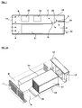
- FIG. 1 is a schematic plan view illustrating a structure of an apparatus for cooling inverter according to a first exemplary embodiment of the present disclosure, where an interior of housing (10) is illustrated from an upper side.
- the apparatus is arranged inside a housing (10) of square shape, where an inlet (11) may be formed at one side of the housing (10) and an outlet (12) may be formed at the other side of the housing (10). That is, air introduced into the inlet (11) of the housing (10) may flow inside the housing (10) to cool electric elements and may be discharged out of the outlet (12).
- the inlet (11) may be installed with a vent hole, for example, and the outlet (12) may be installed with a cooling fan.
- the present disclosure is not limited thereto. That is, the inlet (11) may be installed with a cooling fan and the outlet (12) may be formed with a vent hole. Alternatively, the inlet (11) and the outlet (12) may be respectively formed with a cooling fan to control the flow of air.
- the vent hole is a air flow hole to allow air to be discharged to outside, and functions to introduce the air
- the cooling fan is a device using the air to discharge heat generated by the electric elements to the outside.
- the housing (10) may be such that a first wall (21) is vertically extended from the inlet (11) to divide an interior of the housing (10) to a lengthwise direction.
- the first wall (21) may be extended from the inlet (11) to form a shorter length than that of the housing (10).
- the first wall (21) may include a first flow part (A) and a second flow part (B) in which air flows.
- the housing (10) may be such that a second wall (22) is extended from the outlet (12) to divide an interior of the housing (10) to a lengthwise direction.
- the position of the second wall (22) may be determined by position and size of the outlet (12). That is, unlike FIG. 1 , if the position and size of the outlet (12) correspond to those of the first flow part (A), the first wall (21) and the second wall (22) may be formed on a straight line.
- a third wall (23) connecting the first and second walls (21, 22) may be arranged to form openings (D, E) between the first and second walls (21, 22).
- openings (D, E) between the first and second walls (21, 22).
- the first flow part (A) may be arranged with a first electric element (31), and the second flow part (B) may be arranged with second and third electric elements (32, 33).
- the electric element (31) arranged at the first flow part (A) may be an electric element that generates the greatest heat amount.
- the first electric element (31) may be a heat sink.
- the electric elements (32, 33) arranged at the second flow part (B) may be electric elements that generate smaller heat amount.
- the second and third electric elements (32, 33) may be respectively capacitor and a DCL (DC reactor).
- FIGS.2a is a schematic perspective view illustrating an apparatus for cooling inverter of FIG. 1
- FIG. 2b is a lateral view.
- the first electric element (31) arranged on the first flow part (A) has a greater heat generation, and therefore may be arranged at an upper surface of a guide (34) to allow air to be introduced.
- the guide (34) may be so arranged at a bottom surface of the first electric element (31) as to allow the first electric element (31) to maintain a predetermined gap from a floor of the housing (10), and may be formed at one side with a slope (35) to allow air moving in the first flow part (A) to flow through (see F of FIG. 2b ).
- air introduced through the inlet (11) of the housing (10) may be sucked into the first and second flow parts (A, B).
- the first wall (21) cross-wisely controls the flow of the air.
- the air flowing through the first and second flow parts (A, B) serves to cool the electric elements (31, 32) and is discharged to the outside through the outlet (12) arranged at the other side of the housing (10).
- the first flow part (A) is formed with a straight path through which the air introduced from the inlet (11) can be discharged through the outlet (12), the path being a path where air flow is concentrated, such that the electric element (31) having a greater heat generation is preferably arranged at the first flow part (A). That is, the first flow part (A) arranged with the electric element (31) of greater heat generation is set with a shortest distance between air flow and discharge in order to maximize the heat radiation effect.
- the second flow part (B) is so formed as to allow the air introduced from the inlet (11) to face the outlet (12) through the openings (D, E), where the air flows from a third flow part (C) through the second and third electric elements (32, 33) and is discharged to the outlet (12) through the openings (D, E).
- the size of the opening (D, E) may be determined in consideration of flow amount and speed as the flow is adjusted, and shape of the opening may take a shape of a hole or a surface.
- first, second and third walls (21, 22, 23) may be integrally formed, and the openings (D, E) may be formed in the form of a hole thereamong , or the first, second and third walls (21, 22, 23) may be separately formed, and the openings (D, E) may be formed in the shape of a surface.
- the apparatus according to the exemplary embodiment of the present disclosure as illustrated in FIGS. 1 and 2 has a structure in which the first and second flow parts (A, B) are cross-wisely positioned base on the inlet (11) and the outlet (12), and the apparatus is divided by a right side and a left side based on the inlet (11).
- the present disclosure is not limited thereto, and the first and second flow parts (A, B) may be divided to an upper part and a lower part. That is, electric elements may be arranged by rotating the structure of FIG. 1 by 90°.
- the air that has cooled the electric elements (32, 33) and has been discharged from the second flow part (B) may flow the third flow part (C) and may be discharged to the outlet (12) through the openings (D, E).
- the third flow part (C) in the exemplary embodiment of the present disclosure may be arranged with a fourth electric element (36).
- FIG.3 is an exemplary view illustrating an arrangement of electric elements on a third flow part of FIG. 1 .
- the air discharged through the second flow part (B) flows in the third flow part (C) such that the electric element (36) may be arranged at the third flow part (C), whereby an inner space of the housing (10) can be maximally and efficiently used to reduce the size of the apparatus and to maximized the cooling performance.
- FIG.4 is a schematic plan view illustrating a structure of an apparatus for cooling inverter method for controlling an inverter according to a second exemplary embodiment of the present disclosure.
- the first and second flow parts (A, B) are arranged in consideration of the heat generation by the electric elements (41, 42, 43), where it shows a case where heat generation of electric elements (41, 42) arranged at the first flow part (A) on which the inlet and outlet (11, 12) are straightly arranged is greater than that of the electric element (43) arranged at the second flow part (B).
- the openings (D, E) may be formed in the same direction (E) and vertical direction (D) based on the direction of the outlet (12). That is, the third wall (23) may be vertically arranged relative to the first and second walls (21, 22), unlike in the first exemplary embodiment where a slope is formed.
- Other configuration is same as in the first exemplary embodiment such that no further elaboration will be made.
- FIG. 5 is a schematic plan view illustrating a structure of an apparatus for cooling inverter method for controlling an inverter according to a third exemplary embodiment of the present disclosure, where the second wall (22) may be extended and distanced at a predetermined distance from the housing (10) to form an opening (G), and the third wall (23) may contact the second wall (22) to be slantly formed toward the first wall (21). Furthermore, an electric element (44) may be arranged at the third flow part (C) according to the third exemplary embodiment as shown in FIG. 5 . Under this configuration, the openings (D, G) may be arranged nearest to the outlet (22) to promote the maximum effect of heat radiation.
- FIG. 6 is a schematic plan view illustrating a structure of an apparatus for cooling inverter method for controlling an inverter according to a fourth exemplary embodiment of the present disclosure, where a fourth wall (24) may be arranged in parallel with the first wall (21) to form first to fourth flow parts (I, J, K, L).
- a plurality of walls may be arranged to form a plurality of flow parts, and various structures may be formed according to the number of electric elements.
- the present disclosure is not limited to the number of walls defined in FIG. 6 .
- FIG. 7 is a schematic plan view illustrating a structure of an apparatus for cooling inverter method for controlling an inverter according to a fifth exemplary embodiment of the present disclosure, where the first wall (21) is so configured as to allow air to be smoothly flowed.
- FIG. 7 has illustrated the first wall (21) in the shape of a zigzag, the present disclosure is not limited thereto, and various structures may be proposed in consideration of size of the outlet (12) and size of the housing (10).
Landscapes
- Engineering & Computer Science (AREA)
- Microelectronics & Electronic Packaging (AREA)
- Physics & Mathematics (AREA)
- Thermal Sciences (AREA)
- Inverter Devices (AREA)
- Cooling Or The Like Of Electrical Apparatus (AREA)
- Rectifiers (AREA)
Applications Claiming Priority (1)
| Application Number | Priority Date | Filing Date | Title |
|---|---|---|---|
| KR20130103758A KR20150025755A (ko) | 2013-08-30 | 2013-08-30 | 인버터 냉각장치 |
Publications (2)
| Publication Number | Publication Date |
|---|---|
| EP2843700A2 true EP2843700A2 (de) | 2015-03-04 |
| EP2843700A3 EP2843700A3 (de) | 2015-06-17 |
Family
ID=51359328
Family Applications (1)
| Application Number | Title | Priority Date | Filing Date |
|---|---|---|---|
| EP14181783.3A Withdrawn EP2843700A3 (de) | 2013-08-30 | 2014-08-21 | Vorrichtung zum Kühlen eines Inverters |
Country Status (5)
| Country | Link |
|---|---|
| US (1) | US9622390B2 (de) |
| EP (1) | EP2843700A3 (de) |
| JP (1) | JP2015050929A (de) |
| KR (1) | KR20150025755A (de) |
| CN (1) | CN104426389B (de) |
Cited By (1)
| Publication number | Priority date | Publication date | Assignee | Title |
|---|---|---|---|---|
| EP3518639A1 (de) * | 2018-01-30 | 2019-07-31 | LSIS Co., Ltd. | Umrichter und verfahren zur steuerung davon |
Families Citing this family (20)
| Publication number | Priority date | Publication date | Assignee | Title |
|---|---|---|---|---|
| US8743549B2 (en) | 2011-03-22 | 2014-06-03 | Amazon Technologies, Inc. | Modular mass storage system |
| US9807911B1 (en) * | 2014-06-10 | 2017-10-31 | Amazon Technologies, Inc. | Computer system with external bypass air plenum |
| JP6285299B2 (ja) | 2014-07-07 | 2018-02-28 | 東芝三菱電機産業システム株式会社 | 半導体装置 |
| JP6559771B2 (ja) | 2014-09-16 | 2019-08-14 | エスゼット ディージェイアイ テクノロジー カンパニー リミテッドSz Dji Technology Co.,Ltd | 放熱装置及びこの放熱装置を用いるuav |
| CN204669236U (zh) * | 2015-06-15 | 2015-09-23 | 阳光电源股份有限公司 | 一种逆变器 |
| EP3386285B1 (de) * | 2015-12-02 | 2021-07-07 | Nec Network And Sensor Systems, Ltd. | Elektronikkomponentengehäusevorrichtung und elektronische vorrichtung |
| JP6011735B1 (ja) * | 2016-01-29 | 2016-10-19 | 富士電機株式会社 | 電力変換装置 |
| KR20170097421A (ko) * | 2016-02-18 | 2017-08-28 | 엘에스산전 주식회사 | 2차원 배열 전력변환장치용 냉각 시스템 |
| US9915985B1 (en) * | 2017-01-03 | 2018-03-13 | Quanta Computer Inc. | Chassis for providing distributed airflow |
| RU2673279C1 (ru) * | 2017-06-05 | 2018-11-23 | Максим Антонович Варюхин | Вычислительный блок электронного вычислительного устройства |
| WO2018229902A1 (ja) * | 2017-06-14 | 2018-12-20 | Necプラットフォームズ株式会社 | 筐体、電子機器、冷却方法 |
| US10842048B2 (en) * | 2017-10-23 | 2020-11-17 | Eaton Intelligent Power Limited | Electrical cabinet with vortex-entrained airflow |
| US10908657B2 (en) * | 2019-02-15 | 2021-02-02 | Pensando Systems Inc. | Methods and systems for thermal control |
| CN115151076A (zh) * | 2021-03-29 | 2022-10-04 | 北京小米移动软件有限公司 | 电子设备 |
| KR102660025B1 (ko) * | 2021-03-31 | 2024-04-24 | 엘에스일렉트릭(주) | 반도체 차단기 |
| DE112022007044T5 (de) * | 2022-04-13 | 2025-07-17 | Mitsubishi Electric Corporation | Leistungswandlungsvorrichtung |
| CN219372919U (zh) * | 2022-11-15 | 2023-07-18 | 华为数字能源技术有限公司 | 一种散热装置和电力设备 |
| KR20240163912A (ko) | 2023-05-11 | 2024-11-19 | 엘에스일렉트릭(주) | 인버터 장치 |
| KR20240163910A (ko) | 2023-05-11 | 2024-11-19 | 엘에스일렉트릭(주) | 인버터 장치 |
| KR20240163913A (ko) | 2023-05-11 | 2024-11-19 | 엘에스일렉트릭(주) | 인버터 장치 |
Citations (3)
| Publication number | Priority date | Publication date | Assignee | Title |
|---|---|---|---|---|
| JP2000232792A (ja) * | 1999-02-09 | 2000-08-22 | Fuji Electric Co Ltd | 無停電電源装置 |
| US20060120043A1 (en) * | 2004-12-07 | 2006-06-08 | International Business Machines Corp. | Cooling apparatus for vertically stacked printed circuit boards |
| EP2429275A2 (de) * | 2010-09-10 | 2012-03-14 | Kabushiki Kaisha Yaskawa Denki | Elektronische Vorrichtung |
Family Cites Families (21)
| Publication number | Priority date | Publication date | Assignee | Title |
|---|---|---|---|---|
| JPS6037294A (ja) | 1983-08-11 | 1985-02-26 | Showa Alum Corp | アルミニウム及びその合金のろう付方法 |
| JPS6037294U (ja) * | 1983-08-23 | 1985-03-14 | 富士通株式会社 | 電子装置における冷却構造 |
| JPS6085895U (ja) * | 1983-11-21 | 1985-06-13 | フアナツク株式会社 | 空気冷却装置 |
| WO1988000681A1 (en) * | 1985-07-10 | 1988-01-28 | Archer Aire Industries, Inc. | Air slot cooking grill |
| JP2625866B2 (ja) | 1988-04-26 | 1997-07-02 | 日本電気株式会社 | 電子機器筐体の冷却構造 |
| JP2834996B2 (ja) | 1994-03-17 | 1998-12-14 | 富士通株式会社 | ヒートシンク |
| JP3994235B2 (ja) | 1997-09-19 | 2007-10-17 | 株式会社安川電機 | 制御装置の冷却構造 |
| JP3621298B2 (ja) | 1999-07-06 | 2005-02-16 | 東芝トランスポートエンジニアリング株式会社 | 電力変換装置の冷却装置 |
| GB2369249B (en) | 2000-11-06 | 2004-06-09 | 3Com Corp | Cooling apparatus including a flow guide |
| JP2004088023A (ja) | 2002-08-29 | 2004-03-18 | Toshiba Corp | 筐体内発熱体冷却装置およびパワーエレクトロニクス機器 |
| JP2005348533A (ja) | 2004-06-03 | 2005-12-15 | Fuji Electric Fa Components & Systems Co Ltd | インバータ装置 |
| US7345873B2 (en) * | 2004-09-29 | 2008-03-18 | General Electric Company | System and method for cooling electronic systems |
| US7355850B2 (en) * | 2006-03-31 | 2008-04-08 | National Instruments Corporation | Vented and ducted sub-rack support member |
| JP5148238B2 (ja) | 2007-10-16 | 2013-02-20 | 東海旅客鉄道株式会社 | 高速鉄道車両用電力変換装置 |
| JP5225759B2 (ja) | 2008-06-09 | 2013-07-03 | 株式会社三社電機製作所 | 機器冷却装置 |
| US9192079B2 (en) * | 2008-09-26 | 2015-11-17 | Rockwell Automation Technologies, Inc. | Power electronic module cooling system and method |
| JP5657260B2 (ja) * | 2010-03-03 | 2015-01-21 | 三和パッキング工業株式会社 | 回路基板の放熱構造 |
| JP5309089B2 (ja) | 2010-06-25 | 2013-10-09 | 株式会社日立製作所 | 電力変換装置および電力変換ユニットの冷却方法 |
| JP5554651B2 (ja) | 2010-07-12 | 2014-07-23 | 東芝三菱電機産業システム株式会社 | 電力変換装置 |
| JP2012164939A (ja) | 2011-02-09 | 2012-08-30 | Toshiba Corp | 電子機器 |
| CN202978741U (zh) | 2012-10-29 | 2013-06-05 | 特变电工新疆新能源股份有限公司 | 一种光伏逆变器功率柜 |
-
2013
- 2013-08-30 KR KR20130103758A patent/KR20150025755A/ko not_active Ceased
-
2014
- 2014-08-20 US US14/464,525 patent/US9622390B2/en active Active
- 2014-08-21 EP EP14181783.3A patent/EP2843700A3/de not_active Withdrawn
- 2014-08-29 CN CN201410438072.4A patent/CN104426389B/zh active Active
- 2014-08-29 JP JP2014174744A patent/JP2015050929A/ja active Pending
Patent Citations (3)
| Publication number | Priority date | Publication date | Assignee | Title |
|---|---|---|---|---|
| JP2000232792A (ja) * | 1999-02-09 | 2000-08-22 | Fuji Electric Co Ltd | 無停電電源装置 |
| US20060120043A1 (en) * | 2004-12-07 | 2006-06-08 | International Business Machines Corp. | Cooling apparatus for vertically stacked printed circuit boards |
| EP2429275A2 (de) * | 2010-09-10 | 2012-03-14 | Kabushiki Kaisha Yaskawa Denki | Elektronische Vorrichtung |
Cited By (4)
| Publication number | Priority date | Publication date | Assignee | Title |
|---|---|---|---|---|
| EP3518639A1 (de) * | 2018-01-30 | 2019-07-31 | LSIS Co., Ltd. | Umrichter und verfahren zur steuerung davon |
| KR20190092012A (ko) * | 2018-01-30 | 2019-08-07 | 엘에스산전 주식회사 | 인버터 및 이의 제어방법 |
| KR102064247B1 (ko) | 2018-01-30 | 2020-02-11 | 엘에스산전 주식회사 | 인버터 및 이의 제어방법 |
| US11013153B2 (en) | 2018-01-30 | 2021-05-18 | Lsis Co., Ltd. | Inverter and method of controlling the same |
Also Published As
| Publication number | Publication date |
|---|---|
| CN104426389A (zh) | 2015-03-18 |
| US9622390B2 (en) | 2017-04-11 |
| US20150062812A1 (en) | 2015-03-05 |
| KR20150025755A (ko) | 2015-03-11 |
| EP2843700A3 (de) | 2015-06-17 |
| CN104426389B (zh) | 2018-03-09 |
| JP2015050929A (ja) | 2015-03-16 |
Similar Documents
| Publication | Publication Date | Title |
|---|---|---|
| US9622390B2 (en) | Apparatus for cooling inverter | |
| KR101189451B1 (ko) | 인버터 스택 | |
| EP2830404A2 (de) | Kühlvorrichtung | |
| EP2603068B1 (de) | Vorrichtung und Verfahren unter Verwendung von Induktion zur Verbesserung von natürlicher Konvektionskühlung | |
| KR101927742B1 (ko) | 유도 가열 조리기기 | |
| EP1936283A2 (de) | Kochvorrichtung | |
| EP2170029A2 (de) | Elektronisches Leistungsmodulkühlsystem und Verfahren | |
| US9545037B2 (en) | Systems and methods for cooling electric drives | |
| JP5309089B2 (ja) | 電力変換装置および電力変換ユニットの冷却方法 | |
| EP2977995A1 (de) | Kühlstruktur für magnetische komponente und stromwandler damit | |
| JP5704760B2 (ja) | 急速充電器 | |
| EP2672618A1 (de) | Modularer Motorwechselrichter mit durch Kühlkörper gebildeten inneren Kühlkanal und ringförmigen Kondensator auf der Aussenseite | |
| US10206310B2 (en) | Electronics assemblies incorporating three-dimensional heat flow structures | |
| CN107432100B (zh) | 用于开关柜空气调节的冷却设备 | |
| JP7236235B2 (ja) | 冷却装置 | |
| US10098256B2 (en) | Electronic device | |
| CN104620485B (zh) | 空调机的变换器装置 | |
| JP2019525477A (ja) | 電子部品パッケージ | |
| JP5468690B2 (ja) | 機器冷却装置 | |
| CN204792426U (zh) | 用于功率电子设备的冷却装置 | |
| JP2018145873A (ja) | 給水装置 | |
| JP4396626B2 (ja) | 電力変換装置 | |
| CN220292392U (zh) | 电控盒和包括电控盒的空调器 | |
| JP6439523B2 (ja) | 電力変換装置 | |
| KR20190135872A (ko) | 냉각 장치 |
Legal Events
| Date | Code | Title | Description |
|---|---|---|---|
| 17P | Request for examination filed |
Effective date: 20140821 |
|
| AK | Designated contracting states |
Kind code of ref document: A2 Designated state(s): AL AT BE BG CH CY CZ DE DK EE ES FI FR GB GR HR HU IE IS IT LI LT LU LV MC MK MT NL NO PL PT RO RS SE SI SK SM TR |
|
| AX | Request for extension of the european patent |
Extension state: BA ME |
|
| PUAI | Public reference made under article 153(3) epc to a published international application that has entered the european phase |
Free format text: ORIGINAL CODE: 0009012 |
|
| PUAL | Search report despatched |
Free format text: ORIGINAL CODE: 0009013 |
|
| AK | Designated contracting states |
Kind code of ref document: A3 Designated state(s): AL AT BE BG CH CY CZ DE DK EE ES FI FR GB GR HR HU IE IS IT LI LT LU LV MC MK MT NL NO PL PT RO RS SE SI SK SM TR |
|
| AX | Request for extension of the european patent |
Extension state: BA ME |
|
| RIC1 | Information provided on ipc code assigned before grant |
Ipc: H01L 23/467 20060101AFI20150513BHEP Ipc: H02M 1/00 20070101ALI20150513BHEP Ipc: H05K 7/20 20060101ALI20150513BHEP |
|
| R17P | Request for examination filed (corrected) |
Effective date: 20151216 |
|
| RBV | Designated contracting states (corrected) |
Designated state(s): AL AT BE BG CH CY CZ DE DK EE ES FI FR GB GR HR HU IE IS IT LI LT LU LV MC MK MT NL NO PL PT RO RS SE SI SK SM TR |
|
| 17Q | First examination report despatched |
Effective date: 20160531 |
|
| STAA | Information on the status of an ep patent application or granted ep patent |
Free format text: STATUS: THE APPLICATION IS DEEMED TO BE WITHDRAWN |
|
| 18D | Application deemed to be withdrawn |
Effective date: 20190917 |