EP2170029A2 - Elektronisches Leistungsmodulkühlsystem und Verfahren - Google Patents
Elektronisches Leistungsmodulkühlsystem und Verfahren Download PDFInfo
- Publication number
- EP2170029A2 EP2170029A2 EP09171516A EP09171516A EP2170029A2 EP 2170029 A2 EP2170029 A2 EP 2170029A2 EP 09171516 A EP09171516 A EP 09171516A EP 09171516 A EP09171516 A EP 09171516A EP 2170029 A2 EP2170029 A2 EP 2170029A2
- Authority
- EP
- European Patent Office
- Prior art keywords
- air
- heatsink
- cooling air
- cooling
- motor drive
- Prior art date
- Legal status (The legal status is an assumption and is not a legal conclusion. Google has not performed a legal analysis and makes no representation as to the accuracy of the status listed.)
- Withdrawn
Links
- 238000001816 cooling Methods 0.000 title claims abstract description 110
- 238000000034 method Methods 0.000 title claims description 13
- 238000011144 upstream manufacturing Methods 0.000 claims description 13
- 230000004888 barrier function Effects 0.000 claims description 2
- 239000007787 solid Substances 0.000 claims description 2
- 230000007246 mechanism Effects 0.000 abstract description 6
- 230000000694 effects Effects 0.000 description 4
- 239000003990 capacitor Substances 0.000 description 3
- 230000017525 heat dissipation Effects 0.000 description 3
- 230000003247 decreasing effect Effects 0.000 description 2
- 230000003292 diminished effect Effects 0.000 description 2
- 238000012986 modification Methods 0.000 description 2
- 230000004048 modification Effects 0.000 description 2
- XUIMIQQOPSSXEZ-UHFFFAOYSA-N Silicon Chemical compound [Si] XUIMIQQOPSSXEZ-UHFFFAOYSA-N 0.000 description 1
- 230000008859 change Effects 0.000 description 1
- 238000006243 chemical reaction Methods 0.000 description 1
- 230000003750 conditioning effect Effects 0.000 description 1
- 238000000605 extraction Methods 0.000 description 1
- 238000009499 grossing Methods 0.000 description 1
- 238000012544 monitoring process Methods 0.000 description 1
- 238000013021 overheating Methods 0.000 description 1
- 230000001105 regulatory effect Effects 0.000 description 1
- 229910052710 silicon Inorganic materials 0.000 description 1
- 239000010703 silicon Substances 0.000 description 1
- 238000012546 transfer Methods 0.000 description 1
Images


Classifications
-
- H—ELECTRICITY
- H05—ELECTRIC TECHNIQUES NOT OTHERWISE PROVIDED FOR
- H05K—PRINTED CIRCUITS; CASINGS OR CONSTRUCTIONAL DETAILS OF ELECTRIC APPARATUS; MANUFACTURE OF ASSEMBLAGES OF ELECTRICAL COMPONENTS
- H05K7/00—Constructional details common to different types of electric apparatus
- H05K7/20—Modifications to facilitate cooling, ventilating, or heating
- H05K7/2089—Modifications to facilitate cooling, ventilating, or heating for power electronics, e.g. for inverters for controlling motor
- H05K7/20909—Forced ventilation, e.g. on heat dissipaters coupled to components
- H05K7/20918—Forced ventilation, e.g. on heat dissipaters coupled to components the components being isolated from air flow, e.g. hollow heat sinks, wind tunnels or funnels
-
- H—ELECTRICITY
- H05—ELECTRIC TECHNIQUES NOT OTHERWISE PROVIDED FOR
- H05K—PRINTED CIRCUITS; CASINGS OR CONSTRUCTIONAL DETAILS OF ELECTRIC APPARATUS; MANUFACTURE OF ASSEMBLAGES OF ELECTRICAL COMPONENTS
- H05K7/00—Constructional details common to different types of electric apparatus
- H05K7/20—Modifications to facilitate cooling, ventilating, or heating
- H05K7/20009—Modifications to facilitate cooling, ventilating, or heating using a gaseous coolant in electronic enclosures
- H05K7/20136—Forced ventilation, e.g. by fans
- H05K7/20154—Heat dissipaters coupled to components
- H05K7/20163—Heat dissipaters coupled to components the components being isolated from air flow, e.g. hollow heat sinks, wind tunnels or funnels
Definitions
- the invention relates generally to the field of power electronic devices such as those used in power conversion or for applying power to motors and other loads. More particularly, the invention relates to a power electronic module with an improved cooling arrangement which provides enhanced air flow characteristics and enhanced heat dissipation.
- circuitry In the field of power electronic devices, a wide range of circuitry is known and currently available for converting, producing and applying power to loads. Depending upon the application, such circuitry may convert incoming power from one form to another as needed by the load. In a typical arrangement, for example, constant (or varying) frequency alternating current power (such as from a utility grid or generator) is converted to controlled frequency alternating current power to drive motors, and other loads. In this type of application, the frequency of the output power can be regulated to control the speed of the motor or other device. Many other applications exist, however, for power electronic circuits which can convert alternating current power to direct current power, or vice versa, or that otherwise manipulate, filter, or modify electric signals for powering a load.
- Circuits of this type generally include rectifiers (converters), inverters, and similar switched circuitry.
- a motor drive will typically include a rectifier that converts AC power to DC.
- power conditioning circuits such as capacitors and/or inductors, are employed to remove unwanted voltage ripple on the internal DC bus.
- Inverter circuitry can then convert the DC signal into an AC signal of a particular frequency desired for driving a motor at a particular speed.
- the inverter circuitry typically includes several high power switches, such as insulated-gate bipolar transistors (IGBTs), controlled by drive circuitry.
- IGBTs insulated-gate bipolar transistors
- the motor drive circuitry detailed above will typically generate substantial amounts of heat, which must be dissipated to avoid damaging heat sensitive electronics. Typically, therefore, some form of cooling mechanism is usually employed to enhance heat extraction and dissipation. Often, the motor drive circuitry is packaged together as a unit with a built-in cooling channel that carries cool air to several components. Because the air within the channel is heated as it travels through the channel, components near the exhaust end of the air channel will usually experience a diminished cooling effect. Therefore, as packaged control units become more compact, the need for efficient heat dissipation becomes more critical.
- the temperature of the inverter circuitry e.g., the IGBTs
- the power output of the unit is often, therefore, limited by the maximum temperature that the inverter circuitry can handle without substantially increasing the risk of failure.
- a more effective cooling mechanism that provides additional cooling for the inverter circuitry would, therefore, allow the motor drive to operate at higher motor speeds.
- a motor drive with an improved cooling mechanism.
- a cooling mechanism that provides increased cooling for the inverter circuitry of a power electronic module such as a motor drive.
- the present invention relates generally to a cooling configuration designed to address such needs.
- One embodiment employs an air passageway configured to allow cooling air to bypass a portion of a heatsink adjacent to the rectifier circuitry and direct cooling air into an area of the heatsink that is nearer to the inverter circuitry.
- Another embodiment employs an air passageway with an air directing structure configured to provide an air flow that impinges on a lateral surface of the heatsink.
- the air directing structure is chosen to provide a turbulent air flow in the heat dissipating structure within the vicinity of the inverter circuitry.
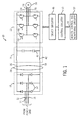
- FIG. 1 is a diagrammatical representation of an exemplary motor drive circuit in accordance with one embodiment of the present invention
- FIG. 2 is a perspective view of an exemplary motor drive unit in accordance with one embodiment of the present invention.
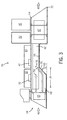
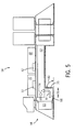
- FIGS. 3-5 are cross sectional views of the motor drive unit shown in FIG. 2 , illustrating exemplary air passageways with exemplary air directing structures.
- FIG. 1 is a diagrammatical representation of an exemplary motor drive circuit 10 employing an air passageway with an air directing structure for providing enhanced cooling of the motor drive circuitry.
- the motor drive circuit 10 includes a three phase power source electrically coupled to a set of input terminals 12, 14 and 16 that provides three phase AC power of constant frequency to a rectifier circuitry 18.
- a set of six silicon-controlled rectifiers (SCRs) 32 provide full wave rectification of the three phase voltage waveform.
- SCRs silicon-controlled rectifiers
- Inductors 42 are coupled to both the high and low sides of the DC bus 34 and act as a choke for smoothing the rectified DC voltage waveform.
- Capacitors 40 link the high side 36 of the DC bus 34 with the low side 38 of the DC bus 34 and are also configured to smooth the rectified DC voltage waveform. Together, the inductors and capacitors serve to remove most of the AC ripple presented by the rectifier circuitry 18 so that the DC bus 34 carries a waveform closely approximating a true DC voltage. It should be noted that the three-phase implementation described herein is not intended to be limiting, and the invention may be employed on single-phase circuitry, as well as on circuitry designed for applications other than motor drives.
- An inverter 22 is coupled to the DC bus 34 and generates a three phase output waveform at a desired frequency for driving a motor 30 connected to the output terminals 24, 26 and 28.
- two switches 44 are coupled in series, collector to emitter, between the high side 36 and low side 38 of the DC bus 34. Three of these switch pairs are then coupled in parallel to the DC bus 34, for a total of six switches 44.
- Each switch 44 is paired with a flyback diode 46 such that the collector is coupled to the anode and the emitter is coupled to the cathode.
- Each of the output terminals 24, 26 and 28 is coupled to one of the switch outputs between one of the pairs of switches 44.
- the driver circuitry 48 signals the switches 44 to rapidly close and open, resulting in a three phase waveform output across output terminals 24, 26 and 28.
- the driver circuitry 48 is controlled by the control circuitry 50, which responds to the remote control and monitoring circuitry 52 through the network 54.
- motor control circuit 10 will usually be packaged within a unit that includes a cooling channel and a heatsink, as shown in FIG. 2
- the motor drive unit 56 includes a cooling channel 58 enclosed by side plates.
- the motor drive unit 56 also includes a set of fans 60 to provide a flow of cooling air through the cooling channel 58.
- the SCRs 32, IGBTs 44, driver circuitry 48, and the control circuitry 50 are situated above and adjacent to the cooling channel 58 so that the flow of cool air draws heat from the circuitry.
- the SCRs 32 will generally be grouped together with the control circuitry 50 near the input of the cooling channel 58, and the IGBTs 44 will generally be grouped together with the driver circuitry 48 further downstream, i.e. toward the exhaust end of the cooling channel 58.
- the downstream circuitry such as the IGBTs 44
- Embodiments of the present invention provide improved cooling techniques that allow the cooling effects of the cooling air to be shifted downstream, toward the IGBT circuitry, as will be explained below in respect to FIGS. 3-5 .
- FIG. 3 is a cross-sectional view of the control unit 56, and provides a better view of cooling channel 58.
- the cooling channel 58 includes a heatsink 62 mounted below a lower plate 64 adjacent to the SCRs 32, the IGBTs 44, the driver circuitry 48, and the control circuitry 50.
- the heatsink 62 may include a series of parallel fins oriented toward the fans 60 to allow cooling air from the fans 60 to pass between the fins. Cooling air may also pass between the fins at a lateral face 66 of the heatsink 62.
- Also inside the cooling channel 58 is an open passageway 68 located adjacent to the heatsink 62 and extending some portion of the length of the heatsink 62.
- the open passageway 68 allows some portion of the air entering the cooling channel 58 to bypass the heatsink 62 for a certain distance.
- the cooling channel 58 also includes an air directing structure 70 positioned below the heatsink 62 and configured to direct air into a lateral face 66 of the heatsink 62.
- the air directing structure 70 may be formed by the bottom plate 72 of the cooling channel 58 as shown in FIG. 3 , or alternatively, the air directing structure 70 may be a separate baffle located inside the cooling channel 58.
- the cooling channel 58 provides improved cooling properties over the prior art by shifting a portion of the cooling air to a downstream location and by imparting an angular direction to the air flow.
- cooling air is forced by the fans 60 into the cooling channel 58, at which point, some of the air enters the leading edge of the heatsink 62, as illustrated by arrow 74, while some portion of the air enters the open passageway 68.
- the air entering the leading edge of the heatsink 62 will be warmed by the control circuitry 50 and the SCRs 32.
- the open passageway 68 is not significantly thermally coupled to the heatsink 62, the air passing through the open passageway 68 will be relatively cool. Air entering the open passageway 68 is later forced up into the heatsink 62 by the air directing structure 70 at a location downstream from the control circuitry 50 and the SCRs 32, as illustrated by arrow 76.
- the combined temperature of the cooling air adjacent to the driver circuitry 48 and the IGBTs 42 may be reduced, making those components relatively cooler.
- the flow of cooling air adjacent to the control circuitry 50 and the SCRs 32 will be reduced, making those components relatively warmer. It can be seen, therefore, that using the techniques described above, the cooling influence of the air flow in the channel 58 may be shifted from an upstream location to a downstream location. In this way, the cooling air may be directed to circuitry that may have a greater need for cooling, such as the IGBTs 42, for example.
- the degree of air flow shifting will depend on the setback 78 of the air directing structure 70.
- the setback 78 is defined at the distance from the leading edge of the heatsink 62 to the point at which the air directing structure 70 meets the heatsink 62, as shown in FIG. 3 .
- the setback 78 of the air directing structure 70 may be selected to coincide with the leading edge of the IGBTs 42, so as to favor increased cooling for the IGBTs 42, as shown in FIG. 3 .
- the setback 78 may be increased or decreased to change the distribution of cooling air, and thereby favor certain components or spread the heat dissipation more evenly.
- the setback 78 may range from ten percent to ninety percent of the length of the heatsink 62, as shown in FIGS. 4 and 5 .
- the air directing baffle 70 may also impart a directional component to the air that is perpendicular to the face of the heatsink, causing an angular airflow relative to the face of the heatsink. This angular, or impingent, air flow may tend to force cooler air deeper into the heatsink, closer to the heat source, while forcing warmed air out toward the exhaust of the heatsink. In this way, the rate of heat transfer from the heatsink 62 to the cooling air may be increased.
- the angularity of the air flow depends, at least in part, on the angle 80 of the air directing structure 70. Furthermore, the angle selection may also affect the overall air flow resistance of the channel. In some embodiments, the angle 80 may be approximately forty-five degrees, as shown in FIG. 3 . By orienting the air directing structure 70 to form an angle 80 of forty-five degrees a substantial level of angularity may be imparted to the air flow while, at the same time, maintaining a relatively low overall air flow resistance. In other embodiments, the angularity of the air flow and the air flow resistance may be increased or decreased by changing the angle 80 as shown in FIGS 4 and 5 , which are described below. In various embodiments, the angle 80 may range from 10 to 170 degrees.
- FIGS. 4 and 5 additional embodiments of a motor drive unit with exemplary cooling channels are shown.
- the angle 80 of the air directing structure 70 is approximately ten degrees and the setback distance 78 is approximately ninety percent of the length of the heatsink 62.
- the air in open passageway 68 is guided into the heatsink 62 more gradually compared to the embodiment of FIG 3 .
- the relatively large setback may tend to shift cooling air further downstream, providing enhanced cooling to downstream components.
- the relatively small angle reduces the angularity of the cooling air flowing through the heatsink 62.
- the large setback in combination with the small angle tends to cause cooling air to be gradually guided into the heatsink 62 along a large portion of the lateral face 68 of the heatsink 62, as indicated by the arrows 82.
- the cooling effects of the cooling air may be more evenly distributed between the upstream and downstream components.
- the small angle 80 may also decrease the overall airflow resistance of the cooling channel 58.
- the angle 80 of the air directing structure 70 is approximately ninety degrees and the setback distance 78 is approximately ten percent of the length of the heatsink 62.
- the air in open passageway 68 is guided into the heatsink 62 more abruptly compared to the embodiment of FIG 3 .
- the ninety degree angle of the directing structure 70 increases the angularity of the cooling air flowing through the heatsink 62 in the vicinity of the upstream components, as indicated by the arrow 84.
- the relatively short setback distance will tend to allow very little downstream shifting of cooling air, providing additional cooling air to components further upstream.
- the small setback in combination with the ninety degree angle, may tend to focus cooling effects of the cooling air on the upstream components, causing more heat to be extracted from the upstream components, such as the SCRs.
- the ninety degree angle may also tend to increase the overall airflow resistance of the cooling channel 58.
- an embodiment may include a setback distance of approximately 60 percent and an angle of approximately ninety degrees, thereby creating an air flow under the IGBTs with a high degree of angularity.
- the angle 80 of the air directing structure may be up to 170 degrees, in which case the air directing structure may form a pocket of air that the cooling air travels past before being directed into the heatsink.
Landscapes
- Engineering & Computer Science (AREA)
- Microelectronics & Electronic Packaging (AREA)
- Physics & Mathematics (AREA)
- Thermal Sciences (AREA)
- Motor Or Generator Cooling System (AREA)
- Inverter Devices (AREA)
- Cooling Or The Like Of Electrical Apparatus (AREA)
Applications Claiming Priority (1)
| Application Number | Priority Date | Filing Date | Title |
|---|---|---|---|
| US12/239,009 US9192079B2 (en) | 2008-09-26 | 2008-09-26 | Power electronic module cooling system and method |
Publications (1)
| Publication Number | Publication Date |
|---|---|
| EP2170029A2 true EP2170029A2 (de) | 2010-03-31 |
Family
ID=41351761
Family Applications (1)
| Application Number | Title | Priority Date | Filing Date |
|---|---|---|---|
| EP09171516A Withdrawn EP2170029A2 (de) | 2008-09-26 | 2009-09-28 | Elektronisches Leistungsmodulkühlsystem und Verfahren |
Country Status (2)
| Country | Link |
|---|---|
| US (1) | US9192079B2 (de) |
| EP (1) | EP2170029A2 (de) |
Cited By (6)
| Publication number | Priority date | Publication date | Assignee | Title |
|---|---|---|---|---|
| CN102222902A (zh) * | 2011-06-17 | 2011-10-19 | 辽宁荣信众腾科技有限公司 | 可移动式轻型直流输电系统整体结构 |
| CN102751883A (zh) * | 2011-04-18 | 2012-10-24 | 株式会社安川电机 | 电力变换装置 |
| WO2012062711A3 (de) * | 2010-11-10 | 2012-11-15 | Abb Technology Ag | Baugruppe zum kühlen von leistungshalbleitern |
| CN103259421A (zh) * | 2013-05-15 | 2013-08-21 | 清源科技(厦门)股份有限公司 | 一种光伏逆变器 |
| EP3633842A4 (de) * | 2017-05-30 | 2021-01-13 | Daikin Industries, Ltd. | Leistungsumwandlungsvorrichtung und kältevorrichtung |
| CN112863826A (zh) * | 2019-11-12 | 2021-05-28 | 致茂电子(苏州)有限公司 | 平板变压器 |
Families Citing this family (35)
| Publication number | Priority date | Publication date | Assignee | Title |
|---|---|---|---|---|
| DE102010028927A1 (de) * | 2010-05-12 | 2011-11-17 | Zf Friedrichshafen Ag | Leistungselektronikanordnung |
| JP5348623B2 (ja) * | 2010-09-10 | 2013-11-20 | 株式会社安川電機 | 電子機器装置 |
| KR101189451B1 (ko) * | 2010-12-24 | 2012-10-09 | 엘지전자 주식회사 | 인버터 스택 |
| US20120221288A1 (en) * | 2011-02-28 | 2012-08-30 | General Electric Company, A New York Corporation | System and Methods for Improving Power Handling of an Electronic Device |
| US20120221287A1 (en) * | 2011-02-28 | 2012-08-30 | General Electric Company, A New York Corporation | System and Methods for Improving Power Handling of an Electronic Device |
| KR20150025755A (ko) * | 2013-08-30 | 2015-03-11 | 엘에스산전 주식회사 | 인버터 냉각장치 |
| US9578786B1 (en) * | 2014-06-10 | 2017-02-21 | Amazon Technologies, Inc. | Computer system with bypass air plenum |
| JP6559771B2 (ja) * | 2014-09-16 | 2019-08-14 | エスゼット ディージェイアイ テクノロジー カンパニー リミテッドSz Dji Technology Co.,Ltd | 放熱装置及びこの放熱装置を用いるuav |
| WO2016139763A1 (ja) * | 2015-03-04 | 2016-09-09 | 株式会社日立製作所 | 電力変換ユニットおよび電力変換装置 |
| US10477724B2 (en) * | 2015-03-09 | 2019-11-12 | Datalogic IP Tech, S.r.l. | Efficient heat exchange systems and methods |
| JP5939329B1 (ja) * | 2015-03-20 | 2016-06-22 | 日本電気株式会社 | 冷却構造、及び装置 |
| CN204669236U (zh) * | 2015-06-15 | 2015-09-23 | 阳光电源股份有限公司 | 一种逆变器 |
| JP2017153166A (ja) * | 2016-02-22 | 2017-08-31 | 株式会社明電舎 | 電気機器収納盤 |
| JP6048607B1 (ja) * | 2016-04-15 | 2016-12-21 | 富士電機株式会社 | 鉄道車両用電力変換装置 |
| JP6652467B2 (ja) * | 2016-08-31 | 2020-02-26 | 株式会社日立製作所 | 電力変換装置および電力変換装置を搭載した鉄道車両 |
| US10024326B2 (en) * | 2016-12-05 | 2018-07-17 | Asia Vital Components Co., Ltd. | Series fan with support frame |
| US10212838B2 (en) * | 2017-01-13 | 2019-02-19 | Cree Fayetteville, Inc. | High power multilayer module having low inductance and fast switching for paralleling power devices |
| JP6852494B2 (ja) * | 2017-03-22 | 2021-03-31 | コニカミノルタ株式会社 | 光書き込み装置及び画像形成装置 |
| US10143117B2 (en) * | 2017-04-06 | 2018-11-27 | Chyng Hong Electronic Co., Ltd. | High power density DC-AC power inverter |
| JP6888468B2 (ja) * | 2017-08-01 | 2021-06-16 | 富士電機株式会社 | 鉄道車両用電力変換装置 |
| JP6954029B2 (ja) * | 2017-11-15 | 2021-10-27 | 富士電機株式会社 | 電力変換装置および鉄道車両用電力変換装置 |
| JP7027140B2 (ja) * | 2017-12-04 | 2022-03-01 | 株式会社東芝 | 電力変換装置及び鉄道車両 |
| JP6918765B2 (ja) * | 2018-11-29 | 2021-08-11 | ファナック株式会社 | 放熱装置 |
| CN119095336A (zh) * | 2019-01-18 | 2024-12-06 | 比泽尔电子股份公司 | 电子功率设备和冷却回路 |
| US10908657B2 (en) * | 2019-02-15 | 2021-02-02 | Pensando Systems Inc. | Methods and systems for thermal control |
| CN111162458A (zh) * | 2020-01-18 | 2020-05-15 | 西安精石电气科技有限公司 | 一种并离网切换装置和集控链储能系统 |
| US11863083B2 (en) * | 2020-04-16 | 2024-01-02 | Eaton Intelligent Power Limited | Rectifier assembly |
| US11690195B2 (en) | 2020-09-11 | 2023-06-27 | Abb Schweiz Ag | Power semiconductor cooling system |
| FR3114352B1 (fr) * | 2020-09-23 | 2023-01-06 | Safran | Echangeur de chaleur double flux |
| US12108581B2 (en) * | 2021-12-28 | 2024-10-01 | Ubicquia, Inc. | Multi-chambered shield enclosure for vertically stacked module arrangement and electronic apparatus incorporating same |
| US12101111B2 (en) * | 2021-12-28 | 2024-09-24 | Ubicquia, Inc. | Small cell access node with water intrusion mitigation |
| US11792964B2 (en) * | 2021-12-28 | 2023-10-17 | Ubicquia, Inc. | Electronic apparatus with channeled cooling |
| US11844151B2 (en) | 2022-01-01 | 2023-12-12 | Ubicquia, Inc. | Small cell access node |
| CN217825777U (zh) * | 2022-06-02 | 2022-11-15 | 阳光电源股份有限公司 | 散热组件和电能转换器 |
| DE102022114113A1 (de) * | 2022-06-03 | 2023-12-14 | Dr. Ing. H.C. F. Porsche Aktiengesellschaft | Pulswechselrichter mit einer Kühleinrichtung sowie Kraftfahrzeug mit einem Pulswechselrichter |
Family Cites Families (51)
| Publication number | Priority date | Publication date | Assignee | Title |
|---|---|---|---|---|
| DE3041656A1 (de) * | 1980-11-05 | 1982-05-13 | SEMIKRON Gesellschaft für Gleichrichterbau u. Elektronik mbH, 8500 Nürnberg | Halbleiter-schaltungsaufbau |
| US4520425A (en) * | 1982-08-12 | 1985-05-28 | Mitsubishi Denki Kabushiki Kaisha | Control apparatus with improved structure for cooling circuit elements |
| US4872102A (en) * | 1986-04-28 | 1989-10-03 | Dimensions Unlimited, Inc. | D.C. to A.C. inverter having improved structure providing improved thermal dissipation |
| KR920005988B1 (ko) * | 1988-08-31 | 1992-07-25 | 가부시기가이샤 히다찌세이사꾸쇼 | 인버터장치 |
| US5170336A (en) * | 1990-03-05 | 1992-12-08 | Dimensions Unlimited, Inc. | DC to AC inverter with improved forced air cooling method and apparatus |
| JP2809026B2 (ja) * | 1992-09-30 | 1998-10-08 | 三菱電機株式会社 | インバ−タ装置およびインバ−タ装置の使用方法 |
| JPH07194139A (ja) * | 1993-12-27 | 1995-07-28 | Hitachi Ltd | 電気自動車用インバータの冷却装置 |
| US5610493A (en) * | 1995-04-12 | 1997-03-11 | Allen-Bradley Company, Inc. | Terminal configuration for a motor controller |
| US5699609A (en) * | 1995-04-12 | 1997-12-23 | Allen-Bradley Company, Inc. | Method of making power substrate assembly |
| US5623191A (en) * | 1995-04-12 | 1997-04-22 | Allen-Bradley Company, Inc. | Circuit board architecture for a motor controller |
| US5563768A (en) * | 1995-08-31 | 1996-10-08 | At&T Global Information Solutions Company | Heat source cooling apparatus and method utilizing mechanism for dividing a flow of cooling fluid |
| US5648892A (en) * | 1995-09-29 | 1997-07-15 | Allen-Bradley Company, Inc. | Wireless circuit board system for a motor controller |
| DE19607226A1 (de) * | 1996-02-27 | 1997-09-04 | Metabowerke Kg | Akku-Ladegerät für Elektrohandwerkzeuge |
| US5742478A (en) * | 1996-09-25 | 1998-04-21 | Wu; Chih-Hsien | Radiating structure of a power converter |
| TW470873B (en) * | 1998-01-02 | 2002-01-01 | Delta Electronics Inc | Miniaturization of power supply system of portable computer by improving heat dissipation |
| JP4066282B2 (ja) * | 1998-05-26 | 2008-03-26 | 株式会社安川電機 | 電気機器 |
| US6046908A (en) * | 1998-09-04 | 2000-04-04 | Long Well Electronics Corp. | Heat-radiating structure of power adapter |
| DE19983152T1 (de) * | 1999-02-24 | 2001-05-31 | Mitsubishi Electric Corp | Leistungstreibervorrichtung |
| US6087800A (en) * | 1999-03-12 | 2000-07-11 | Eaton Corporation | Integrated soft starter for electric motor |
| US6359779B1 (en) * | 1999-04-05 | 2002-03-19 | Western Digital Ventures, Inc. | Integrated computer module with airflow accelerator |
| US6198642B1 (en) * | 1999-10-19 | 2001-03-06 | Tracewell Power, Inc. | Compact multiple output power supply |
| JP3852253B2 (ja) | 1999-10-21 | 2006-11-29 | 富士通株式会社 | 電子部品の冷却装置及び電子機器 |
| CA2408286C (en) * | 2000-05-08 | 2009-01-06 | Siemens Aktiengesellschaft | Control device |
| US6515858B2 (en) | 2000-06-06 | 2003-02-04 | Unipower Corporation | Thermal distribution system |
| SE0003189D0 (sv) | 2000-09-08 | 2000-09-08 | Emerson Energy Systems Ab | A spring device for pressing an electronic component towards a heat sink body |
| DE10058574B4 (de) * | 2000-11-24 | 2005-09-15 | Danfoss Drives A/S | Kühlgerät für Leistungshalbleiter |
| JP4108348B2 (ja) | 2002-02-19 | 2008-06-25 | 株式会社三社電機製作所 | 電源装置 |
| US6678157B1 (en) * | 2002-09-17 | 2004-01-13 | Sun Microsystems, Inc. | Electronics assembly with cooling arrangement |
| US6891725B2 (en) | 2002-09-23 | 2005-05-10 | Siemens Energy & Automation, Inc. | System and method for improved motor controller |
| US6621700B1 (en) * | 2002-09-26 | 2003-09-16 | Chromalox, Inc. | Heat sink for a silicon controlled rectifier power controller |
| US6826035B2 (en) * | 2002-09-26 | 2004-11-30 | Chromalox, Inc. | Silicon controlled rectifier power controller |
| JP2005044953A (ja) | 2003-07-28 | 2005-02-17 | Hitachi Industrial Equipment Systems Co Ltd | 電力変換装置 |
| US7149064B2 (en) * | 2003-08-29 | 2006-12-12 | Rockwell Automation Technologies, Inc. | Multiphase reduced voltage starter with bypass relays, interphase electrical isolation and shared thermal mass |
| US7027300B2 (en) | 2003-09-16 | 2006-04-11 | Mobility Electronics, Inc. | Compact electronics plenum |
| GB2411050A (en) * | 2004-02-16 | 2005-08-17 | E2V Tech Uk Ltd | Electrical apparatus cooling system |
| DE102004017292A1 (de) * | 2004-04-05 | 2005-10-20 | Siemens Ag | Motorsteuergerät |
| US7085136B2 (en) * | 2004-04-14 | 2006-08-01 | Thermaltake Technology Ltd. | Heat duct-equipped heat-radiating device for power supply |
| US7042745B1 (en) * | 2004-11-29 | 2006-05-09 | Cotek Electronic Ind. Co. Ltd. | Insulating arrangement for DC/AC inverter |
| US7265985B2 (en) * | 2004-12-29 | 2007-09-04 | Motorola, Inc. | Heat sink and component support assembly |
| FR2881018B1 (fr) * | 2005-01-19 | 2007-04-06 | Intelligent Electronic Systems | Procede de refroidissement d'un dispositif de conversion statique d'electronique de puissance et dispositif correspondant |
| JP4848209B2 (ja) * | 2006-05-31 | 2011-12-28 | 株式会社日立産機システム | 電力変換装置 |
| US7554804B2 (en) * | 2006-06-30 | 2009-06-30 | Siemens Energy & Automation, Inc. | Electronic module configured for air flow therethrough and system including same |
| CN101513150B (zh) * | 2006-09-04 | 2011-08-10 | 株式会社安川电机 | 马达控制器 |
| US7817421B2 (en) * | 2006-09-13 | 2010-10-19 | Kabushiki Kaisha Yaskawa Denki | Motor controller |
| DE102007003329B3 (de) * | 2007-01-17 | 2008-04-10 | Siemens Ag | Kühlanordnung für in einem Gehäuse angeordnete elektrische Komponenten eines Sanftanlaufgerätes, und Sanftanlaufgerät |
| US7616442B1 (en) * | 2008-04-25 | 2009-11-10 | Rockwell Automation Technologies, Inc. | Power electronic module cooling system and method |
| FI20085945L (fi) * | 2008-10-08 | 2010-04-09 | Abb Oy | Elektroniikkalaitteen jäähdytysrakenne ja menetelmä |
| JP5720977B2 (ja) * | 2010-07-20 | 2015-05-20 | 株式会社安川電機 | マトリクスコンバータ |
| JP2012228018A (ja) * | 2011-04-18 | 2012-11-15 | Yaskawa Electric Corp | 電力変換装置 |
| EP2557676B1 (de) * | 2011-08-09 | 2014-02-26 | Siemens Aktiengesellschaft | Umrichteranordnung mit einem Luftkühlsystem |
| CN104145333B (zh) * | 2012-04-16 | 2018-02-02 | 富士电机株式会社 | 半导体装置以及半导体装置用冷却器 |
-
2008
- 2008-09-26 US US12/239,009 patent/US9192079B2/en active Active
-
2009
- 2009-09-28 EP EP09171516A patent/EP2170029A2/de not_active Withdrawn
Cited By (9)
| Publication number | Priority date | Publication date | Assignee | Title |
|---|---|---|---|---|
| WO2012062711A3 (de) * | 2010-11-10 | 2012-11-15 | Abb Technology Ag | Baugruppe zum kühlen von leistungshalbleitern |
| CN102751883A (zh) * | 2011-04-18 | 2012-10-24 | 株式会社安川电机 | 电力变换装置 |
| US8797738B2 (en) | 2011-04-18 | 2014-08-05 | Kabushiki Kaisha Yaskawa Denki | Power converting apparatus |
| CN102222902A (zh) * | 2011-06-17 | 2011-10-19 | 辽宁荣信众腾科技有限公司 | 可移动式轻型直流输电系统整体结构 |
| CN102222902B (zh) * | 2011-06-17 | 2013-09-25 | 中国海洋石油总公司 | 可移动式轻型直流输电系统整体结构 |
| CN103259421A (zh) * | 2013-05-15 | 2013-08-21 | 清源科技(厦门)股份有限公司 | 一种光伏逆变器 |
| EP3633842A4 (de) * | 2017-05-30 | 2021-01-13 | Daikin Industries, Ltd. | Leistungsumwandlungsvorrichtung und kältevorrichtung |
| CN112863826A (zh) * | 2019-11-12 | 2021-05-28 | 致茂电子(苏州)有限公司 | 平板变压器 |
| CN112863826B (zh) * | 2019-11-12 | 2022-05-17 | 致茂电子(苏州)有限公司 | 平板变压器 |
Also Published As
| Publication number | Publication date |
|---|---|
| US20100079944A1 (en) | 2010-04-01 |
| US9192079B2 (en) | 2015-11-17 |
Similar Documents
| Publication | Publication Date | Title |
|---|---|---|
| US9192079B2 (en) | Power electronic module cooling system and method | |
| US7616442B1 (en) | Power electronic module cooling system and method | |
| US8004836B2 (en) | Arrangement for a motor controller | |
| US9084376B2 (en) | Heat sink cooling arrangement for multiple power electronic circuits | |
| KR101144409B1 (ko) | 전력 변환 장치 | |
| CN110520982A (zh) | 半导体布置 | |
| Venkatramanan et al. | Design and comparative study of discrete and module-based IGBT power converters | |
| US12408310B2 (en) | Power converter, heat exchanger, heat sink, and photovoltaic power generation system | |
| JP4848209B2 (ja) | 電力変換装置 | |
| WO2022062767A1 (zh) | 一种逆变装置及其功率控制方法 | |
| JP2001163065A (ja) | 電子部品の冷却装置及び冷却ユニット | |
| CN210956653U (zh) | 用于冷却变流器的功率半导体器件的装置和轨道车辆 | |
| JP2003259657A (ja) | 電力変換装置 | |
| JP5078794B2 (ja) | 加熱調理器 | |
| CN207150437U (zh) | 用于将dc电力转换为三相ac电力的转换系统以及包括该转换系统的电动机系统 | |
| CN109617374A (zh) | 一种变流器模块、变流器和变流器冷却系统 | |
| CN209104144U (zh) | 冷却式电气设备组件 | |
| Mirza et al. | A three-face utilized heat sink design for 3-D integrated 75 kVA intelligent power stage (IPS) | |
| CN114121927A (zh) | 半导体电路及其应用装置 | |
| JP7316193B2 (ja) | 電力変換装置 | |
| CN223694048U (zh) | 电路板及电源模块 | |
| JP7783548B2 (ja) | プリント回路板、およびそれを有する空気調和装置 | |
| CN205160343U (zh) | 变频器的散热组件 | |
| JP2015233375A (ja) | 力率改善モジュール及びこれを用いた電力変換装置 | |
| CN119866001A (zh) | 一种储能逆变器的散热结构及其散热方法 |
Legal Events
| Date | Code | Title | Description |
|---|---|---|---|
| PUAI | Public reference made under article 153(3) epc to a published international application that has entered the european phase |
Free format text: ORIGINAL CODE: 0009012 |
|
| AK | Designated contracting states |
Kind code of ref document: A2 Designated state(s): AT BE BG CH CY CZ DE DK EE ES FI FR GB GR HR HU IE IS IT LI LT LU LV MC MK MT NL NO PL PT RO SE SI SK SM TR |
|
| AX | Request for extension of the european patent |
Extension state: AL BA RS |
|
| STAA | Information on the status of an ep patent application or granted ep patent |
Free format text: STATUS: THE APPLICATION HAS BEEN WITHDRAWN |
|
| 18W | Application withdrawn |
Effective date: 20130624 |