EP2841237B2 - Handführbare werkzeugmaschine mit gehäuse - Google Patents
Handführbare werkzeugmaschine mit gehäuse Download PDFInfo
- Publication number
- EP2841237B2 EP2841237B2 EP13721257.7A EP13721257A EP2841237B2 EP 2841237 B2 EP2841237 B2 EP 2841237B2 EP 13721257 A EP13721257 A EP 13721257A EP 2841237 B2 EP2841237 B2 EP 2841237B2
- Authority
- EP
- European Patent Office
- Prior art keywords
- outer housing
- machine tool
- hand
- electric drive
- support devices
- Prior art date
- Legal status (The legal status is an assumption and is not a legal conclusion. Google has not performed a legal analysis and makes no representation as to the accuracy of the status listed.)
- Active
Links
Images


Classifications
-
- B—PERFORMING OPERATIONS; TRANSPORTING
- B25—HAND TOOLS; PORTABLE POWER-DRIVEN TOOLS; MANIPULATORS
- B25F—COMBINATION OR MULTI-PURPOSE TOOLS NOT OTHERWISE PROVIDED FOR; DETAILS OR COMPONENTS OF PORTABLE POWER-DRIVEN TOOLS NOT PARTICULARLY RELATED TO THE OPERATIONS PERFORMED AND NOT OTHERWISE PROVIDED FOR
- B25F5/00—Details or components of portable power-driven tools not particularly related to the operations performed and not otherwise provided for
- B25F5/006—Vibration damping means
-
- B—PERFORMING OPERATIONS; TRANSPORTING
- B25—HAND TOOLS; PORTABLE POWER-DRIVEN TOOLS; MANIPULATORS
- B25F—COMBINATION OR MULTI-PURPOSE TOOLS NOT OTHERWISE PROVIDED FOR; DETAILS OR COMPONENTS OF PORTABLE POWER-DRIVEN TOOLS NOT PARTICULARLY RELATED TO THE OPERATIONS PERFORMED AND NOT OTHERWISE PROVIDED FOR
- B25F5/00—Details or components of portable power-driven tools not particularly related to the operations performed and not otherwise provided for
- B25F5/001—Gearings, speed selectors, clutches or the like specially adapted for rotary tools
-
- B—PERFORMING OPERATIONS; TRANSPORTING
- B25—HAND TOOLS; PORTABLE POWER-DRIVEN TOOLS; MANIPULATORS
- B25F—COMBINATION OR MULTI-PURPOSE TOOLS NOT OTHERWISE PROVIDED FOR; DETAILS OR COMPONENTS OF PORTABLE POWER-DRIVEN TOOLS NOT PARTICULARLY RELATED TO THE OPERATIONS PERFORMED AND NOT OTHERWISE PROVIDED FOR
- B25F5/00—Details or components of portable power-driven tools not particularly related to the operations performed and not otherwise provided for
- B25F5/02—Construction of casings, bodies or handles
Definitions
- the present invention relates to a hand-held oscillating machine tool with an outer housing extending substantially along a longitudinal axis, which has a handle area provided for gripping and guiding the machine tool by a user's hand.
- Hand-held machine tools are known from the prior art, the housings of which are either firmly screwed to the drive devices of the machine tool or have housings which consist of shell components, usually half shells, which are firmly connected to one another.
- the housings of the machine tools known from the prior art rest at least partially on the elements of the drive device, whereby vibrations from these drive devices are transmitted directly to the housing, which then vibrates with the drive devices, thereby impairing the work safety and handling comfort of such a machine tool.
- EP 1 752 259 A1 discloses an electric hand tool comprising a motor arranged in a motor housing and a gear for coupling the motor to a tool, wherein the gear is mounted in a separate gear housing, wherein the motor is fixed to the gear housing and freely arranged in the motor housing and the gear housing is connected to the motor housing in a vibration-decoupled manner.
- the invention is therefore based on the object of providing a hand-held machine tool with improved handling comfort.
- the tool device serves to transmit the drive torque of the electric drive unit to a tool that is preferably arranged on the tool device.
- the tool device can have various elements such as gears, clutches and the like. Both the electric drive unit and the tool unit can be designed in several parts.
- the machine tool preferably has a tool holder at the end of the tool device opposite the electric drive unit, the drive axis of which can also be arranged pivoted at an angle to the drive axis of the electric drive element.
- the tool holder can be arranged at an outer end of the drive axis, but it can also be arranged in an area spaced from the end of the tool device.
- the tool holder can also be arranged in a recess in the area of the drive shaft in the tool device, into which a tool can be inserted.
- the tools that can be used with the machine tool are used in particular for cutting, drilling, grinding, sawing, rasping or for other machining, removing or forming processes. Due to the drive and machining processes on the machining tool and the mass inertia of the machining tool, which is arranged on the tool device, vibrations and shocks occur on the tool device.
- This minimum distance and the air layer lying between the outer contour and the inner contour lead to a mechanical decoupling of the electric drive device and the tool device from the outer housing and thus to increased handling comfort.
- the minimum distance also reduces the heat transferred from the drive unit and the tool device to the housing, which also increases handling comfort for the user.
- At least one damping element is arranged between a first support device and a second support device, which transmits the support forces between a first and a second support device and at the same time maintains the minimum distance between the outer contour and the inner contour.
- the first and second support devices thus enable sufficient transmission of the support forces such as the guide forces from the user to the machine tool and the processing forces from the tool to the user.
- the second support devices are also preferably arranged outside the handle area on the outer housing.
- the inner contour of the outer housing is arranged in the handle area at a minimum distance from the outer contour of the drive elements of the machine tool and can preferably move in this area relative to the outer contour according to the elasticity of the outer housing, which also results in a certain mechanical decoupling of the handle area from the drive elements. This also contributes to the improved handling comfort of the machine tool.
- At least two arrangements of first and second support devices are arranged as far apart from each other as possible.
- at least one arrangement of first and second support devices is arranged on the tool device and at least one other arrangement of first and second support devices is arranged on the end of the electric drive unit opposite the tool device.
- the at least one arrangement of first and second support devices on the tool device enables the user to guide the machine tool well.
- the at least one arrangement of first and second support devices on the end of the electric drive unit opposite the tool device enables a sufficient connection of the electric drive unit to the outer housing and thus, in conjunction with the arrangement of first and second support devices on the tool unit, a sufficient transmission of the user's guiding forces to the drive devices of the machine tool.
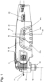
- the tool device 15 has a drive shaft 16 that is driven in an oscillating manner about a drive axis 17, the drive axis 17 being arranged pivoted downwards by 90° relative to the axis of rotation of the electric drive device, which in the exemplary embodiment coincides with the longitudinal axis 11 of the machine tool.
- a tool holder 18 At the end of the drive shaft 16 there is a tool holder 18 for holding a suitable machining tool.
- the masses of the on/off switch 22 and the power regulator 23 shift the center of mass 27 of the outer housing 12 backwards along the longitudinal axis 11 of the machine tool in the direction of the second end area, which is in a direction facing away from the first end area.
- a second center of mass 27b of the outer housing 12 is shown in the area of the geometric center 29 of the outer housing 10, which in Fig.1 is represented by the axis 29.
- the optimal center of mass 27 of the outer housing 12 shown as an example is located approximately in the middle of the handle area 21 of the machine tool 10 and is indicated by the center of mass 27c shown.
- a first support device 31 is arranged on the tool device 15 in the area in which it is accommodated in the outer housing 12.
- a further first support device 32 is arranged in the rear area of the electric drive unit 14.
- First support devices 31 and 32 are also arranged in the same position on the hidden, opposite side of the tool device 15 and the electric drive unit 14. This means that two first support devices 31 are arranged in front of the handle area 21 at the level of the axis of rotation of the electric drive device 14, which serve to transmit the support forces from the tool device 15 to the outer housing 12.
- Two first support devices 32 are also arranged behind the handle area 21 at a distance from the longitudinal axis 11 on the side of the electric drive device 14 which is opposite the tool device 15.
- first support devices 32 are arranged behind the handle area 21, which serve to transmit the support forces from the electric drive device 14 to the outer housing 12.
- Second support devices are arranged on the two housing halves, which interact with the first support devices 31 and 32 in order to support the outer contour and the inner contour at a distance a which is at least Minimum distance a from each other.
- Fig.4 shows an enlarged view of a section through an arrangement of first and second support devices 31 and 36 with a damping element 39 arranged between them.
- the first support device 31 is designed in the form of a rotationally symmetrical depression, which has the shape of a hollow dome in its end region.
- the second support device 36 is designed in the form of a rotationally symmetrical pin, which has a corresponding dome-shaped design in its end region.
- this exemplary embodiment uses first and second support devices 31, 32, 36 between which a damping element 39 is arranged.
- the supporting forces are supported via the first and second supporting devices 31, 32, 36 relative to the outer housing 12, wherein the outer housing 12 is essentially mechanically decoupled from the electric drive unit 14 and the tool device 15.
Landscapes
- Engineering & Computer Science (AREA)
- Mechanical Engineering (AREA)
- Auxiliary Devices For Machine Tools (AREA)
- Percussive Tools And Related Accessories (AREA)
- Portable Power Tools In General (AREA)
- Harvester Elements (AREA)
Applications Claiming Priority (2)
| Application Number | Priority Date | Filing Date | Title |
|---|---|---|---|
| DE102012103604A DE102012103604A1 (de) | 2012-04-24 | 2012-04-24 | Handführbare Werkzeugmaschine mit Gehäuse |
| PCT/EP2013/001206 WO2013159903A2 (de) | 2012-04-24 | 2013-04-22 | Handführbare werkzeugmaschine mit gehäuse |
Publications (3)
| Publication Number | Publication Date |
|---|---|
| EP2841237A2 EP2841237A2 (de) | 2015-03-04 |
| EP2841237B1 EP2841237B1 (de) | 2021-01-06 |
| EP2841237B2 true EP2841237B2 (de) | 2024-07-10 |
Family
ID=48326233
Family Applications (1)
| Application Number | Title | Priority Date | Filing Date |
|---|---|---|---|
| EP13721257.7A Active EP2841237B2 (de) | 2012-04-24 | 2013-04-22 | Handführbare werkzeugmaschine mit gehäuse |
Country Status (6)
| Country | Link |
|---|---|
| US (1) | US10160111B2 (da) |
| EP (1) | EP2841237B2 (da) |
| CN (1) | CN104245238B (da) |
| DE (1) | DE102012103604A1 (da) |
| DK (1) | DK2841237T4 (da) |
| WO (1) | WO2013159903A2 (da) |
Families Citing this family (9)
| Publication number | Priority date | Publication date | Assignee | Title |
|---|---|---|---|---|
| US10232479B2 (en) * | 2013-05-06 | 2019-03-19 | Milwaukee Electric Tool Corporation | Power tool including a battery pack isolation system |
| CN105835012B (zh) | 2015-02-02 | 2020-08-21 | 株式会社牧田 | 作业工具 |
| CN105881461B (zh) | 2015-02-15 | 2021-11-16 | 苏州宝时得电动工具有限公司 | 动力工具 |
| EP3357645B1 (en) * | 2016-02-19 | 2019-11-27 | Makita Corporation | Work tool |
| JP6703417B2 (ja) * | 2016-02-19 | 2020-06-03 | 株式会社マキタ | 作業工具 |
| JP6795309B2 (ja) * | 2016-02-19 | 2020-12-02 | 株式会社マキタ | 作業工具 |
| US10220501B1 (en) * | 2016-06-15 | 2019-03-05 | George P. Davidson | Pocket door repair tool |
| DE102019200317A1 (de) * | 2019-01-14 | 2020-07-16 | Robert Bosch Gmbh | Handwerkzeugmaschine |
| EP4119299A1 (de) * | 2021-07-12 | 2023-01-18 | Hilti Aktiengesellschaft | Handwerkzeugmaschine und verwendung einer handwerkzeugmaschine |
Citations (1)
| Publication number | Priority date | Publication date | Assignee | Title |
|---|---|---|---|---|
| EP1550532A1 (de) † | 2003-12-30 | 2005-07-06 | Robert Bosch Gmbh | Handwerkzeugmaschine mit Schwingungsdämpfung |
Family Cites Families (73)
| Publication number | Priority date | Publication date | Assignee | Title |
|---|---|---|---|---|
| US2341497A (en) * | 1939-11-22 | 1944-02-08 | Chicago Pneumatic Tool Co | Impact tool |
| DE1948055A1 (de) * | 1969-09-23 | 1971-04-01 | Impex Essen Vertrieb | Elektrisch betriebener Bohrhammer |
| US4217677A (en) * | 1978-03-13 | 1980-08-19 | Kure Tekko Company Ltd. | Apparatus for preventing transmission of vibration of a vibration machine |
| US4747455A (en) * | 1983-05-02 | 1988-05-31 | Jbd Corporation | High impact device and method |
| DE3335005A1 (de) * | 1983-09-28 | 1985-04-18 | Robert Bosch Gmbh, 7000 Stuttgart | Kraftbetriebenes handwerkzeug mit einem druckluftmotor |
| JP2534318B2 (ja) * | 1988-04-30 | 1996-09-11 | 日立工機株式会社 | 動力工具の防振ハンドル |
| US4905772A (en) * | 1988-09-01 | 1990-03-06 | Honsa Thomas W | Rotary power tool with vibration damping |
| US4879847A (en) * | 1989-03-13 | 1989-11-14 | Snap-On Tools Corporation | Cover for pneumatic tool |
| DE4000861C3 (de) * | 1990-01-13 | 1999-04-08 | Atlas Copco Electric Tools | Handgeführte Schlagbohrmaschine mit Schwingungsdämpfung |
| US5394039A (en) * | 1993-01-19 | 1995-02-28 | Ryobi Outdoor Products Inc. | Electric motor mount having vibration damping |
| DE4329804A1 (de) * | 1993-09-03 | 1995-03-09 | Behr Gmbh & Co | Halterung für einen Elektromotor insbesondere für ein Gebläserad einer Heizungs- oder Klimaanlage |
| JPH0825249A (ja) * | 1994-07-12 | 1996-01-30 | Makita Corp | 振動工具及び防振リング |
| US5533579A (en) * | 1994-10-31 | 1996-07-09 | Chu; Eric | Shock preventive pneumatic tool as automatically shut off under no load condition |
| DE19512804C2 (de) * | 1995-04-05 | 2000-06-15 | Lucas Ind Plc | Hydraulikaggregat für eine blockiergeschützte Fahrzeugbremsanlage |
| DE29517258U1 (de) * | 1995-10-31 | 1995-12-21 | Cooper Industries, Inc., Houston, Tex. | Werkzeug |
| DE19730356C2 (de) * | 1997-07-15 | 2001-05-17 | Wacker Werke Kg | Schwingungsgedämpfter Aufbruch- und/oder Bohrhammer |
| DE29706216U1 (de) * | 1997-04-08 | 1998-08-06 | ebm Werke GmbH & Co., 74673 Mulfingen | Anordnung zur schwingungsisolierenden Aufhängung eines Elektromotors |
| US5875562A (en) * | 1997-06-18 | 1999-03-02 | Fogarty; Shaun P. | Hand-held hair dryer with vibration and noise control |
| JP3515425B2 (ja) * | 1999-05-24 | 2004-04-05 | 株式会社マキタ | モータの収容構造 |
| DE10034437B4 (de) * | 2000-07-15 | 2011-07-14 | Andreas Stihl AG & Co., 71336 | Handgeführtes Arbeitsgerät |
| US6547208B2 (en) * | 2000-12-27 | 2003-04-15 | Delphi Technologies, Inc. | Motor mounting assembly |
| US6805207B2 (en) * | 2001-01-23 | 2004-10-19 | Black & Decker Inc. | Housing with functional overmold |
| JP2002254336A (ja) * | 2001-03-02 | 2002-09-10 | Hitachi Koki Co Ltd | 電動工具 |
| GB0109747D0 (en) * | 2001-04-20 | 2001-06-13 | Black & Decker Inc | Hammer |
| US20040206523A1 (en) * | 2002-08-06 | 2004-10-21 | Giardino David A. | Control device for a power impact tool |
| JP3818234B2 (ja) * | 2002-07-19 | 2006-09-06 | 日立工機株式会社 | 釘打機 |
| US7152695B2 (en) * | 2002-09-20 | 2006-12-26 | Snap-On Incorporated | Power tool with air seal and vibration dampener |
| JP4647957B2 (ja) * | 2004-08-27 | 2011-03-09 | 株式会社マキタ | 作業工具 |
| JP4524168B2 (ja) | 2004-10-20 | 2010-08-11 | リョービ株式会社 | 手持ち式電動工具 |
| JP4857542B2 (ja) * | 2004-10-29 | 2012-01-18 | 日立工機株式会社 | 動力工具 |
| GB2421000A (en) * | 2004-12-07 | 2006-06-14 | Black & Decker Inc | Vibration attenuated power tool |
| GB2422569A (en) * | 2005-01-26 | 2006-08-02 | Black & Decker Inc | Rotary hammer |
| DE102005016453A1 (de) * | 2005-04-11 | 2006-10-12 | Robert Bosch Gmbh | Handwerkzeugmaschine |
| SE529839C2 (sv) * | 2005-05-26 | 2007-12-04 | Atlas Copco Constr Tools Ab | Brytverktyg med avvibrerad handtagsanordning |
| ATE389514T1 (de) | 2005-08-11 | 2008-04-15 | Metabowerke Gmbh | Elektrohandwerkzeuggerät |
| JP2007050454A (ja) * | 2005-08-12 | 2007-03-01 | Hitachi Koki Co Ltd | インパクト工具 |
| WO2007048435A1 (de) * | 2005-10-29 | 2007-05-03 | Aeg Electric Tools Gmbh | Handwerkzeugmaschine |
| DE102005061870A1 (de) * | 2005-12-23 | 2007-07-05 | Robert Bosch Gmbh | Handwerkzeugmaschine |
| DE202005020647U1 (de) | 2005-12-29 | 2006-05-11 | Robert Bosch Gmbh | Handwerkzeugmaschine, insbesondere Bohr- und/oder Meißelhammer |
| DE102006027774A1 (de) | 2006-06-16 | 2007-12-20 | Robert Bosch Gmbh | Handwerkzeugmaschine |
| US8590633B2 (en) * | 2006-07-01 | 2013-11-26 | Black & Decker Inc. | Beat piece wear indicator for powered hammer |
| DE102006054288A1 (de) * | 2006-11-17 | 2008-05-21 | A & M Electric Tools Gmbh | Bohrhammer |
| WO2008097555A1 (en) * | 2007-02-07 | 2008-08-14 | Robert Bosch Gmbh | Vibration dampening for a power tool |
| DE102007000131A1 (de) * | 2007-03-07 | 2008-09-11 | Hilti Ag | Handwerkzeugmaschine mit pneumatischem Schlagwerk |
| US8038133B2 (en) * | 2007-09-13 | 2011-10-18 | Mcpherson Mathew A | Coaxial tube damper |
| JP5171397B2 (ja) * | 2007-09-18 | 2013-03-27 | 株式会社マキタ | 手持式作業工具 |
| WO2009045187A1 (en) * | 2007-10-01 | 2009-04-09 | Carrier Corporation | Screw compressor pulsation damper |
| US7896103B2 (en) * | 2008-02-04 | 2011-03-01 | Ingersoll Rand Company | Power tool housing support structures |
| US20110248583A1 (en) * | 2008-02-07 | 2011-10-13 | Atlas Dynamic Devices, Llc | Power Transmission Tool And System |
| US8196674B2 (en) * | 2008-03-05 | 2012-06-12 | Makita Corporation | Impact tool |
| GB0804967D0 (en) * | 2008-03-18 | 2008-04-16 | Black & Decker Inc | Powered hammer with a vibration dampening mechanism |
| JP5128998B2 (ja) * | 2008-04-04 | 2013-01-23 | 株式会社マキタ | 手持式作業工具 |
| CN201271828Y (zh) * | 2008-09-17 | 2009-07-15 | 南京德朔实业有限公司 | 砂光机 |
| DE102009027688A1 (de) | 2009-01-05 | 2010-07-08 | Robert Bosch Gmbh | Handgehaltene Elektrowerkzeugmaschine |
| DE202009001437U1 (de) | 2009-01-29 | 2010-07-01 | C. & E. Fein Gmbh | Kraftgetriebenes Handwerkzeug |
| JP5345893B2 (ja) * | 2009-05-08 | 2013-11-20 | 株式会社マキタ | 打撃工具 |
| JP5395531B2 (ja) * | 2009-06-19 | 2014-01-22 | 株式会社マキタ | 作業工具 |
| DE102009048322A1 (de) * | 2009-10-05 | 2011-04-07 | Andreas Stihl Ag & Co. Kg | Arbeitsgerät |
| WO2011049496A1 (en) * | 2009-10-23 | 2011-04-28 | Husqvarna Ab | Handheld working tool |
| US9234979B2 (en) * | 2009-12-08 | 2016-01-12 | Magna Closures Inc. | Wide activation angle pinch sensor section |
| US9475180B2 (en) * | 2010-01-07 | 2016-10-25 | Black & Decker Inc. | Power tool having rotary input control |
| DE202010002297U1 (de) * | 2010-02-11 | 2011-06-09 | Illinois Tool Works, Inc., a Delaware Corp., Ill. | Schwingungsdämpfer |
| DE102010013756A1 (de) * | 2010-03-31 | 2011-10-06 | Andreas Stihl Ag & Co. Kg | Handgeführtes Arbeitsgerät |
| DE102010030494A1 (de) * | 2010-06-24 | 2011-12-29 | Robert Bosch Gmbh | Ankerwellenlagereinheit |
| DE102010027205A1 (de) * | 2010-07-06 | 2012-01-12 | C. & E. Fein Gmbh | Handwerkzeug |
| JP5447980B2 (ja) * | 2010-07-16 | 2014-03-19 | 株式会社マキタ | 電動工具におけるブレーキ機構の選択構造 |
| JP5496812B2 (ja) * | 2010-08-03 | 2014-05-21 | 株式会社マキタ | 作業工具 |
| DE102010042452A1 (de) * | 2010-10-14 | 2012-04-19 | Robert Bosch Gmbh | Handwerkzeugmaschine |
| DE102010042605A1 (de) * | 2010-10-19 | 2012-04-19 | Robert Bosch Gmbh | Arbeitswerkzeug, insbesondere Elektrowerkzeug |
| JP5518679B2 (ja) * | 2010-11-16 | 2014-06-11 | 株式会社マキタ | 回転工具 |
| JP5767511B2 (ja) * | 2011-06-01 | 2015-08-19 | 株式会社マキタ | 往復動式作業工具 |
| CN204094755U (zh) * | 2011-06-29 | 2015-01-14 | 英格索尔-兰德公司 | 动力工具罩和动力工具 |
| US10232479B2 (en) * | 2013-05-06 | 2019-03-19 | Milwaukee Electric Tool Corporation | Power tool including a battery pack isolation system |
-
2012
- 2012-04-24 DE DE102012103604A patent/DE102012103604A1/de not_active Ceased
-
2013
- 2013-04-22 DK DK13721257.7T patent/DK2841237T4/da active
- 2013-04-22 WO PCT/EP2013/001206 patent/WO2013159903A2/de not_active Ceased
- 2013-04-22 CN CN201380021580.6A patent/CN104245238B/zh active Active
- 2013-04-22 EP EP13721257.7A patent/EP2841237B2/de active Active
- 2013-04-22 US US14/394,180 patent/US10160111B2/en active Active
Patent Citations (1)
| Publication number | Priority date | Publication date | Assignee | Title |
|---|---|---|---|---|
| EP1550532A1 (de) † | 2003-12-30 | 2005-07-06 | Robert Bosch Gmbh | Handwerkzeugmaschine mit Schwingungsdämpfung |
Also Published As
| Publication number | Publication date |
|---|---|
| US10160111B2 (en) | 2018-12-25 |
| EP2841237A2 (de) | 2015-03-04 |
| CN104245238A (zh) | 2014-12-24 |
| EP2841237B1 (de) | 2021-01-06 |
| DK2841237T4 (da) | 2024-10-14 |
| DE102012103604A1 (de) | 2013-10-24 |
| DK2841237T3 (da) | 2021-04-06 |
| WO2013159903A2 (de) | 2013-10-31 |
| WO2013159903A3 (de) | 2014-06-05 |
| CN104245238B (zh) | 2017-03-22 |
| US20150144367A1 (en) | 2015-05-28 |
Similar Documents
| Publication | Publication Date | Title |
|---|---|---|
| EP2841237B2 (de) | Handführbare werkzeugmaschine mit gehäuse | |
| EP2841236B1 (de) | HANDFÜHRBARE WERKZEUGMASCHINE MIT AUßENGEHÄUSE | |
| EP1958735B1 (de) | Handwerkzeuggerät | |
| EP1800805B1 (de) | Handgriff eines handgeführten Werkzeuggerätes | |
| DE112014001999B4 (de) | Handgriffvorrichtung und angetriebenes Werkzeug mit derselben Handgriffvorrichtung | |
| DE102017103262A1 (de) | Werkzeug | |
| DE112014006502T5 (de) | Schlagwerkzeug | |
| EP2160272A1 (de) | Handwerkzeugmaschinengehäuseeinheit | |
| DE102007039580A1 (de) | Antriebsmechanismus für einen Motorfuchsschwanz | |
| WO2018192870A1 (de) | Federkontakt an einem akkumulator | |
| EP3038780B1 (de) | Gegengewichtsvorrichtung | |
| EP3500405A1 (de) | Handwerkzeugmaschine und verfahren zur dämpfung einer handwerkzeugmaschine | |
| DE202020103996U1 (de) | Elektrohammer | |
| EP3369530A1 (de) | Elektrisches arbeitsgerät mit vibrationsentkopplung | |
| EP3533562B1 (de) | Handgeführtes arbeitsgerät | |
| DE202017101409U1 (de) | Hilfsgriff und Arbeitswerkzeug | |
| EP3389952B1 (de) | Akkubetriebene handwerkzeugmaschine iii | |
| EP2127821B1 (de) | Elektrowerkzeug mit Schwingungstilger | |
| DE102012215455A1 (de) | Werkzeugmaschinensystem | |
| DE102013202027A1 (de) | Tragbare Werkzeugmaschine | |
| DE102023206671A1 (de) | Handgerät | |
| EP1674210B1 (de) | Werkzeuggerät mit entkoppeltem Haupthandgriff | |
| EP2700298B1 (de) | Einsatz für Gartenwerkzeug | |
| DE102005062883A1 (de) | Schwingungsreduktion bei Elektrowerkzeugen | |
| DE102012004051A1 (de) | Werkzeugmaschinentrennvorrichtung |
Legal Events
| Date | Code | Title | Description |
|---|---|---|---|
| PUAI | Public reference made under article 153(3) epc to a published international application that has entered the european phase |
Free format text: ORIGINAL CODE: 0009012 |
|
| 17P | Request for examination filed |
Effective date: 20141111 |
|
| AK | Designated contracting states |
Kind code of ref document: A2 Designated state(s): AL AT BE BG CH CY CZ DE DK EE ES FI FR GB GR HR HU IE IS IT LI LT LU LV MC MK MT NL NO PL PT RO RS SE SI SK SM TR |
|
| AX | Request for extension of the european patent |
Extension state: BA ME |
|
| DAX | Request for extension of the european patent (deleted) | ||
| STAA | Information on the status of an ep patent application or granted ep patent |
Free format text: STATUS: EXAMINATION IS IN PROGRESS |
|
| 17Q | First examination report despatched |
Effective date: 20191031 |
|
| TPAC | Observations filed by third parties |
Free format text: ORIGINAL CODE: EPIDOSNTIPA |
|
| GRAP | Despatch of communication of intention to grant a patent |
Free format text: ORIGINAL CODE: EPIDOSNIGR1 |
|
| STAA | Information on the status of an ep patent application or granted ep patent |
Free format text: STATUS: GRANT OF PATENT IS INTENDED |
|
| INTG | Intention to grant announced |
Effective date: 20200716 |
|
| GRAS | Grant fee paid |
Free format text: ORIGINAL CODE: EPIDOSNIGR3 |
|
| GRAA | (expected) grant |
Free format text: ORIGINAL CODE: 0009210 |
|
| STAA | Information on the status of an ep patent application or granted ep patent |
Free format text: STATUS: THE PATENT HAS BEEN GRANTED |
|
| AK | Designated contracting states |
Kind code of ref document: B1 Designated state(s): AL AT BE BG CH CY CZ DE DK EE ES FI FR GB GR HR HU IE IS IT LI LT LU LV MC MK MT NL NO PL PT RO RS SE SI SK SM TR |
|
| REG | Reference to a national code |
Ref country code: GB Ref legal event code: FG4D Free format text: NOT ENGLISH |
|
| REG | Reference to a national code |
Ref country code: AT Ref legal event code: REF Ref document number: 1351859 Country of ref document: AT Kind code of ref document: T Effective date: 20210115 Ref country code: CH Ref legal event code: EP |
|
| REG | Reference to a national code |
Ref country code: DE Ref legal event code: R096 Ref document number: 502013015417 Country of ref document: DE |
|
| REG | Reference to a national code |
Ref country code: IE Ref legal event code: FG4D Free format text: LANGUAGE OF EP DOCUMENT: GERMAN |
|
| REG | Reference to a national code |
Ref country code: DK Ref legal event code: T3 Effective date: 20210330 |
|
| REG | Reference to a national code |
Ref country code: NL Ref legal event code: FP |
|
| REG | Reference to a national code |
Ref country code: SE Ref legal event code: TRGR |
|
| REG | Reference to a national code |
Ref country code: NO Ref legal event code: T2 Effective date: 20210106 |
|
| REG | Reference to a national code |
Ref country code: LT Ref legal event code: MG9D |
|
| PG25 | Lapsed in a contracting state [announced via postgrant information from national office to epo] |
Ref country code: LT Free format text: LAPSE BECAUSE OF FAILURE TO SUBMIT A TRANSLATION OF THE DESCRIPTION OR TO PAY THE FEE WITHIN THE PRESCRIBED TIME-LIMIT Effective date: 20210106 Ref country code: PT Free format text: LAPSE BECAUSE OF FAILURE TO SUBMIT A TRANSLATION OF THE DESCRIPTION OR TO PAY THE FEE WITHIN THE PRESCRIBED TIME-LIMIT Effective date: 20210506 Ref country code: HR Free format text: LAPSE BECAUSE OF FAILURE TO SUBMIT A TRANSLATION OF THE DESCRIPTION OR TO PAY THE FEE WITHIN THE PRESCRIBED TIME-LIMIT Effective date: 20210106 Ref country code: GR Free format text: LAPSE BECAUSE OF FAILURE TO SUBMIT A TRANSLATION OF THE DESCRIPTION OR TO PAY THE FEE WITHIN THE PRESCRIBED TIME-LIMIT Effective date: 20210407 Ref country code: FI Free format text: LAPSE BECAUSE OF FAILURE TO SUBMIT A TRANSLATION OF THE DESCRIPTION OR TO PAY THE FEE WITHIN THE PRESCRIBED TIME-LIMIT Effective date: 20210106 Ref country code: BG Free format text: LAPSE BECAUSE OF FAILURE TO SUBMIT A TRANSLATION OF THE DESCRIPTION OR TO PAY THE FEE WITHIN THE PRESCRIBED TIME-LIMIT Effective date: 20210406 |
|
| PG25 | Lapsed in a contracting state [announced via postgrant information from national office to epo] |
Ref country code: PL Free format text: LAPSE BECAUSE OF FAILURE TO SUBMIT A TRANSLATION OF THE DESCRIPTION OR TO PAY THE FEE WITHIN THE PRESCRIBED TIME-LIMIT Effective date: 20210106 Ref country code: LV Free format text: LAPSE BECAUSE OF FAILURE TO SUBMIT A TRANSLATION OF THE DESCRIPTION OR TO PAY THE FEE WITHIN THE PRESCRIBED TIME-LIMIT Effective date: 20210106 Ref country code: RS Free format text: LAPSE BECAUSE OF FAILURE TO SUBMIT A TRANSLATION OF THE DESCRIPTION OR TO PAY THE FEE WITHIN THE PRESCRIBED TIME-LIMIT Effective date: 20210106 |
|
| PG25 | Lapsed in a contracting state [announced via postgrant information from national office to epo] |
Ref country code: IS Free format text: LAPSE BECAUSE OF FAILURE TO SUBMIT A TRANSLATION OF THE DESCRIPTION OR TO PAY THE FEE WITHIN THE PRESCRIBED TIME-LIMIT Effective date: 20210506 |
|
| REG | Reference to a national code |
Ref country code: DE Ref legal event code: R026 Ref document number: 502013015417 Country of ref document: DE |
|
| PLBI | Opposition filed |
Free format text: ORIGINAL CODE: 0009260 |
|
| PLAX | Notice of opposition and request to file observation + time limit sent |
Free format text: ORIGINAL CODE: EPIDOSNOBS2 |
|
| PG25 | Lapsed in a contracting state [announced via postgrant information from national office to epo] |
Ref country code: EE Free format text: LAPSE BECAUSE OF FAILURE TO SUBMIT A TRANSLATION OF THE DESCRIPTION OR TO PAY THE FEE WITHIN THE PRESCRIBED TIME-LIMIT Effective date: 20210106 Ref country code: CZ Free format text: LAPSE BECAUSE OF FAILURE TO SUBMIT A TRANSLATION OF THE DESCRIPTION OR TO PAY THE FEE WITHIN THE PRESCRIBED TIME-LIMIT Effective date: 20210106 Ref country code: SM Free format text: LAPSE BECAUSE OF FAILURE TO SUBMIT A TRANSLATION OF THE DESCRIPTION OR TO PAY THE FEE WITHIN THE PRESCRIBED TIME-LIMIT Effective date: 20210106 |
|
| 26 | Opposition filed |
Opponent name: SAGITTARIUS INTELLECTUAL PROPERTY CONSULTANTS LTD Effective date: 20210930 |
|
| PG25 | Lapsed in a contracting state [announced via postgrant information from national office to epo] |
Ref country code: ES Free format text: LAPSE BECAUSE OF FAILURE TO SUBMIT A TRANSLATION OF THE DESCRIPTION OR TO PAY THE FEE WITHIN THE PRESCRIBED TIME-LIMIT Effective date: 20210106 Ref country code: MC Free format text: LAPSE BECAUSE OF FAILURE TO SUBMIT A TRANSLATION OF THE DESCRIPTION OR TO PAY THE FEE WITHIN THE PRESCRIBED TIME-LIMIT Effective date: 20210106 Ref country code: SK Free format text: LAPSE BECAUSE OF FAILURE TO SUBMIT A TRANSLATION OF THE DESCRIPTION OR TO PAY THE FEE WITHIN THE PRESCRIBED TIME-LIMIT Effective date: 20210106 Ref country code: RO Free format text: LAPSE BECAUSE OF FAILURE TO SUBMIT A TRANSLATION OF THE DESCRIPTION OR TO PAY THE FEE WITHIN THE PRESCRIBED TIME-LIMIT Effective date: 20210106 |
|
| PLAB | Opposition data, opponent's data or that of the opponent's representative modified |
Free format text: ORIGINAL CODE: 0009299OPPO |
|
| PG25 | Lapsed in a contracting state [announced via postgrant information from national office to epo] |
Ref country code: LU Free format text: LAPSE BECAUSE OF NON-PAYMENT OF DUE FEES Effective date: 20210422 |
|
| R26 | Opposition filed (corrected) |
Opponent name: SCORPIO IP LIMITED Effective date: 20210930 |
|
| PG25 | Lapsed in a contracting state [announced via postgrant information from national office to epo] |
Ref country code: AL Free format text: LAPSE BECAUSE OF FAILURE TO SUBMIT A TRANSLATION OF THE DESCRIPTION OR TO PAY THE FEE WITHIN THE PRESCRIBED TIME-LIMIT Effective date: 20210106 |
|
| PG25 | Lapsed in a contracting state [announced via postgrant information from national office to epo] |
Ref country code: SI Free format text: LAPSE BECAUSE OF FAILURE TO SUBMIT A TRANSLATION OF THE DESCRIPTION OR TO PAY THE FEE WITHIN THE PRESCRIBED TIME-LIMIT Effective date: 20210106 |
|
| PLBB | Reply of patent proprietor to notice(s) of opposition received |
Free format text: ORIGINAL CODE: EPIDOSNOBS3 |
|
| PG25 | Lapsed in a contracting state [announced via postgrant information from national office to epo] |
Ref country code: IT Free format text: LAPSE BECAUSE OF FAILURE TO SUBMIT A TRANSLATION OF THE DESCRIPTION OR TO PAY THE FEE WITHIN THE PRESCRIBED TIME-LIMIT Effective date: 20210106 Ref country code: IE Free format text: LAPSE BECAUSE OF NON-PAYMENT OF DUE FEES Effective date: 20210422 |
|
| PG25 | Lapsed in a contracting state [announced via postgrant information from national office to epo] |
Ref country code: IS Free format text: LAPSE BECAUSE OF FAILURE TO SUBMIT A TRANSLATION OF THE DESCRIPTION OR TO PAY THE FEE WITHIN THE PRESCRIBED TIME-LIMIT Effective date: 20210506 |
|
| PLAB | Opposition data, opponent's data or that of the opponent's representative modified |
Free format text: ORIGINAL CODE: 0009299OPPO |
|
| R26 | Opposition filed (corrected) |
Opponent name: SCORPIO IP LIMITED Effective date: 20210930 |
|
| PG25 | Lapsed in a contracting state [announced via postgrant information from national office to epo] |
Ref country code: HU Free format text: LAPSE BECAUSE OF FAILURE TO SUBMIT A TRANSLATION OF THE DESCRIPTION OR TO PAY THE FEE WITHIN THE PRESCRIBED TIME-LIMIT; INVALID AB INITIO Effective date: 20130422 |
|
| P01 | Opt-out of the competence of the unified patent court (upc) registered |
Effective date: 20230511 |
|
| PG25 | Lapsed in a contracting state [announced via postgrant information from national office to epo] |
Ref country code: CY Free format text: LAPSE BECAUSE OF FAILURE TO SUBMIT A TRANSLATION OF THE DESCRIPTION OR TO PAY THE FEE WITHIN THE PRESCRIBED TIME-LIMIT Effective date: 20210106 |
|
| PG25 | Lapsed in a contracting state [announced via postgrant information from national office to epo] |
Ref country code: MK Free format text: LAPSE BECAUSE OF FAILURE TO SUBMIT A TRANSLATION OF THE DESCRIPTION OR TO PAY THE FEE WITHIN THE PRESCRIBED TIME-LIMIT Effective date: 20210106 |
|
| PUAH | Patent maintained in amended form |
Free format text: ORIGINAL CODE: 0009272 |
|
| STAA | Information on the status of an ep patent application or granted ep patent |
Free format text: STATUS: PATENT MAINTAINED AS AMENDED |
|
| 27A | Patent maintained in amended form |
Effective date: 20240710 |
|
| AK | Designated contracting states |
Kind code of ref document: B2 Designated state(s): AL AT BE BG CH CY CZ DE DK EE ES FI FR GB GR HR HU IE IS IT LI LT LU LV MC MK MT NL NO PL PT RO RS SE SI SK SM TR |
|
| REG | Reference to a national code |
Ref country code: DE Ref legal event code: R102 Ref document number: 502013015417 Country of ref document: DE |
|
| PG25 | Lapsed in a contracting state [announced via postgrant information from national office to epo] |
Ref country code: MT Free format text: LAPSE BECAUSE OF FAILURE TO SUBMIT A TRANSLATION OF THE DESCRIPTION OR TO PAY THE FEE WITHIN THE PRESCRIBED TIME-LIMIT Effective date: 20210106 |
|
| REG | Reference to a national code |
Ref country code: DK Ref legal event code: T4 Effective date: 20241007 |
|
| REG | Reference to a national code |
Ref country code: NL Ref legal event code: FP |
|
| REG | Reference to a national code |
Ref country code: SE Ref legal event code: RPEO |
|
| PGFP | Annual fee paid to national office [announced via postgrant information from national office to epo] |
Ref country code: NL Payment date: 20250422 Year of fee payment: 13 |
|
| PGFP | Annual fee paid to national office [announced via postgrant information from national office to epo] |
Ref country code: DE Payment date: 20250417 Year of fee payment: 13 |
|
| PGFP | Annual fee paid to national office [announced via postgrant information from national office to epo] |
Ref country code: DK Payment date: 20250423 Year of fee payment: 13 |
|
| PGFP | Annual fee paid to national office [announced via postgrant information from national office to epo] |
Ref country code: NO Payment date: 20250422 Year of fee payment: 13 |
|
| PGFP | Annual fee paid to national office [announced via postgrant information from national office to epo] |
Ref country code: BE Payment date: 20250422 Year of fee payment: 13 |
|
| PGFP | Annual fee paid to national office [announced via postgrant information from national office to epo] |
Ref country code: FR Payment date: 20250424 Year of fee payment: 13 |
|
| PGFP | Annual fee paid to national office [announced via postgrant information from national office to epo] |
Ref country code: CH Payment date: 20250501 Year of fee payment: 13 |
|
| PGFP | Annual fee paid to national office [announced via postgrant information from national office to epo] |
Ref country code: AT Payment date: 20250416 Year of fee payment: 13 |
|
| PGFP | Annual fee paid to national office [announced via postgrant information from national office to epo] |
Ref country code: SE Payment date: 20250423 Year of fee payment: 13 |
|
| PG25 | Lapsed in a contracting state [announced via postgrant information from national office to epo] |
Ref country code: TR Free format text: LAPSE BECAUSE OF FAILURE TO SUBMIT A TRANSLATION OF THE DESCRIPTION OR TO PAY THE FEE WITHIN THE PRESCRIBED TIME-LIMIT Effective date: 20210106 |
|
| PGFP | Annual fee paid to national office [announced via postgrant information from national office to epo] |
Ref country code: GB Payment date: 20260324 Year of fee payment: 14 |