EP2841237B2 - Machine tool that can be guided manually and having a housing - Google Patents
Machine tool that can be guided manually and having a housing Download PDFInfo
- Publication number
- EP2841237B2 EP2841237B2 EP13721257.7A EP13721257A EP2841237B2 EP 2841237 B2 EP2841237 B2 EP 2841237B2 EP 13721257 A EP13721257 A EP 13721257A EP 2841237 B2 EP2841237 B2 EP 2841237B2
- Authority
- EP
- European Patent Office
- Prior art keywords
- outer housing
- machine tool
- hand
- electric drive
- support devices
- Prior art date
- Legal status (The legal status is an assumption and is not a legal conclusion. Google has not performed a legal analysis and makes no representation as to the accuracy of the status listed.)
- Active
Links
Images


Classifications
-
- B—PERFORMING OPERATIONS; TRANSPORTING
- B25—HAND TOOLS; PORTABLE POWER-DRIVEN TOOLS; MANIPULATORS
- B25F—COMBINATION OR MULTI-PURPOSE TOOLS NOT OTHERWISE PROVIDED FOR; DETAILS OR COMPONENTS OF PORTABLE POWER-DRIVEN TOOLS NOT PARTICULARLY RELATED TO THE OPERATIONS PERFORMED AND NOT OTHERWISE PROVIDED FOR
- B25F5/00—Details or components of portable power-driven tools not particularly related to the operations performed and not otherwise provided for
- B25F5/006—Vibration damping means
-
- B—PERFORMING OPERATIONS; TRANSPORTING
- B25—HAND TOOLS; PORTABLE POWER-DRIVEN TOOLS; MANIPULATORS
- B25F—COMBINATION OR MULTI-PURPOSE TOOLS NOT OTHERWISE PROVIDED FOR; DETAILS OR COMPONENTS OF PORTABLE POWER-DRIVEN TOOLS NOT PARTICULARLY RELATED TO THE OPERATIONS PERFORMED AND NOT OTHERWISE PROVIDED FOR
- B25F5/00—Details or components of portable power-driven tools not particularly related to the operations performed and not otherwise provided for
- B25F5/001—Gearings, speed selectors, clutches or the like specially adapted for rotary tools
-
- B—PERFORMING OPERATIONS; TRANSPORTING
- B25—HAND TOOLS; PORTABLE POWER-DRIVEN TOOLS; MANIPULATORS
- B25F—COMBINATION OR MULTI-PURPOSE TOOLS NOT OTHERWISE PROVIDED FOR; DETAILS OR COMPONENTS OF PORTABLE POWER-DRIVEN TOOLS NOT PARTICULARLY RELATED TO THE OPERATIONS PERFORMED AND NOT OTHERWISE PROVIDED FOR
- B25F5/00—Details or components of portable power-driven tools not particularly related to the operations performed and not otherwise provided for
- B25F5/02—Construction of casings, bodies or handles
Definitions
- the present invention relates to a hand-held oscillating machine tool with an outer housing extending substantially along a longitudinal axis, which has a handle area provided for gripping and guiding the machine tool by a user's hand.
- Hand-held machine tools are known from the prior art, the housings of which are either firmly screwed to the drive devices of the machine tool or have housings which consist of shell components, usually half shells, which are firmly connected to one another.
- the housings of the machine tools known from the prior art rest at least partially on the elements of the drive device, whereby vibrations from these drive devices are transmitted directly to the housing, which then vibrates with the drive devices, thereby impairing the work safety and handling comfort of such a machine tool.
- EP 1 752 259 A1 discloses an electric hand tool comprising a motor arranged in a motor housing and a gear for coupling the motor to a tool, wherein the gear is mounted in a separate gear housing, wherein the motor is fixed to the gear housing and freely arranged in the motor housing and the gear housing is connected to the motor housing in a vibration-decoupled manner.
- the invention is therefore based on the object of providing a hand-held machine tool with improved handling comfort.
- the tool device serves to transmit the drive torque of the electric drive unit to a tool that is preferably arranged on the tool device.
- the tool device can have various elements such as gears, clutches and the like. Both the electric drive unit and the tool unit can be designed in several parts.
- the machine tool preferably has a tool holder at the end of the tool device opposite the electric drive unit, the drive axis of which can also be arranged pivoted at an angle to the drive axis of the electric drive element.
- the tool holder can be arranged at an outer end of the drive axis, but it can also be arranged in an area spaced from the end of the tool device.
- the tool holder can also be arranged in a recess in the area of the drive shaft in the tool device, into which a tool can be inserted.
- the tools that can be used with the machine tool are used in particular for cutting, drilling, grinding, sawing, rasping or for other machining, removing or forming processes. Due to the drive and machining processes on the machining tool and the mass inertia of the machining tool, which is arranged on the tool device, vibrations and shocks occur on the tool device.
- This minimum distance and the air layer lying between the outer contour and the inner contour lead to a mechanical decoupling of the electric drive device and the tool device from the outer housing and thus to increased handling comfort.
- the minimum distance also reduces the heat transferred from the drive unit and the tool device to the housing, which also increases handling comfort for the user.
- At least one damping element is arranged between a first support device and a second support device, which transmits the support forces between a first and a second support device and at the same time maintains the minimum distance between the outer contour and the inner contour.
- the first and second support devices thus enable sufficient transmission of the support forces such as the guide forces from the user to the machine tool and the processing forces from the tool to the user.
- the second support devices are also preferably arranged outside the handle area on the outer housing.
- the inner contour of the outer housing is arranged in the handle area at a minimum distance from the outer contour of the drive elements of the machine tool and can preferably move in this area relative to the outer contour according to the elasticity of the outer housing, which also results in a certain mechanical decoupling of the handle area from the drive elements. This also contributes to the improved handling comfort of the machine tool.
- At least two arrangements of first and second support devices are arranged as far apart from each other as possible.
- at least one arrangement of first and second support devices is arranged on the tool device and at least one other arrangement of first and second support devices is arranged on the end of the electric drive unit opposite the tool device.
- the at least one arrangement of first and second support devices on the tool device enables the user to guide the machine tool well.
- the at least one arrangement of first and second support devices on the end of the electric drive unit opposite the tool device enables a sufficient connection of the electric drive unit to the outer housing and thus, in conjunction with the arrangement of first and second support devices on the tool unit, a sufficient transmission of the user's guiding forces to the drive devices of the machine tool.
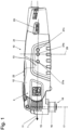
- the tool device 15 has a drive shaft 16 that is driven in an oscillating manner about a drive axis 17, the drive axis 17 being arranged pivoted downwards by 90° relative to the axis of rotation of the electric drive device, which in the exemplary embodiment coincides with the longitudinal axis 11 of the machine tool.
- a tool holder 18 At the end of the drive shaft 16 there is a tool holder 18 for holding a suitable machining tool.
- the masses of the on/off switch 22 and the power regulator 23 shift the center of mass 27 of the outer housing 12 backwards along the longitudinal axis 11 of the machine tool in the direction of the second end area, which is in a direction facing away from the first end area.
- a second center of mass 27b of the outer housing 12 is shown in the area of the geometric center 29 of the outer housing 10, which in Fig.1 is represented by the axis 29.
- the optimal center of mass 27 of the outer housing 12 shown as an example is located approximately in the middle of the handle area 21 of the machine tool 10 and is indicated by the center of mass 27c shown.
- a first support device 31 is arranged on the tool device 15 in the area in which it is accommodated in the outer housing 12.
- a further first support device 32 is arranged in the rear area of the electric drive unit 14.
- First support devices 31 and 32 are also arranged in the same position on the hidden, opposite side of the tool device 15 and the electric drive unit 14. This means that two first support devices 31 are arranged in front of the handle area 21 at the level of the axis of rotation of the electric drive device 14, which serve to transmit the support forces from the tool device 15 to the outer housing 12.
- Two first support devices 32 are also arranged behind the handle area 21 at a distance from the longitudinal axis 11 on the side of the electric drive device 14 which is opposite the tool device 15.
- first support devices 32 are arranged behind the handle area 21, which serve to transmit the support forces from the electric drive device 14 to the outer housing 12.
- Second support devices are arranged on the two housing halves, which interact with the first support devices 31 and 32 in order to support the outer contour and the inner contour at a distance a which is at least Minimum distance a from each other.
- Fig.4 shows an enlarged view of a section through an arrangement of first and second support devices 31 and 36 with a damping element 39 arranged between them.
- the first support device 31 is designed in the form of a rotationally symmetrical depression, which has the shape of a hollow dome in its end region.
- the second support device 36 is designed in the form of a rotationally symmetrical pin, which has a corresponding dome-shaped design in its end region.
- this exemplary embodiment uses first and second support devices 31, 32, 36 between which a damping element 39 is arranged.
- the supporting forces are supported via the first and second supporting devices 31, 32, 36 relative to the outer housing 12, wherein the outer housing 12 is essentially mechanically decoupled from the electric drive unit 14 and the tool device 15.
Landscapes
- Engineering & Computer Science (AREA)
- Mechanical Engineering (AREA)
- Auxiliary Devices For Machine Tools (AREA)
- Percussive Tools And Related Accessories (AREA)
- Portable Power Tools In General (AREA)
- Harvester Elements (AREA)
Description
Die vorliegende Erfindung betrifft eine handführbare Oszillations-Werkzeugmaschine mit einem sich im wesentlichen entlang einer Längsachse erstreckenden Außengehäuse, welches einen Griffbereich aufweist, der zum Umgreifen und zum Führen der Werkzeugmaschine durch eine Hand eines Benutzers vorgesehen ist.The present invention relates to a hand-held oscillating machine tool with an outer housing extending substantially along a longitudinal axis, which has a handle area provided for gripping and guiding the machine tool by a user's hand.
Aus dem Stand der Technik sind handführbare Werkzeugmaschinen bekannt, deren Gehäuse entweder fest mit den Antriebseinrichtungen der Werkzeugmaschine verschraubt sind oder Gehäuse aufweisen, welche aus Schalenbauteilen, zumeist Halbschalen bestehen, die miteinander fest verbunden werden. Um eine gute Führung der handführbaren Werkzeugmaschinen bei der Bearbeitung von Werkstücken zu ermöglichen, liegen die Gehäuse der im Stand der Technik bekannten Werkzeugmaschinen wenigstens bereichsweise an den Elementen der Antriebseinrichtung an, wodurch Vibrationen von diesen Antriebseinrichtungen unmittelbar auf das Gehäuse übertragen werden, welche so mit den Antriebseinrichtungen vibrieren, wodurch die Arbeitssicherheit und der Handhabungskomfort einer solchen Werkzeugmaschine beeinträchtigt wird.Hand-held machine tools are known from the prior art, the housings of which are either firmly screwed to the drive devices of the machine tool or have housings which consist of shell components, usually half shells, which are firmly connected to one another. In order to enable good guidance of the hand-held machine tools when machining workpieces, the housings of the machine tools known from the prior art rest at least partially on the elements of the drive device, whereby vibrations from these drive devices are transmitted directly to the housing, which then vibrates with the drive devices, thereby impairing the work safety and handling comfort of such a machine tool.
Der Erfindung liegt daher die Aufgabe zugrunde, eine handführbare Werkzeugmaschine mit einem verbesserten Handhabungskomfort zur Verfügung zu stellen.The invention is therefore based on the object of providing a hand-held machine tool with improved handling comfort.
Dies wird erfindungsgemäß durch die Lehre des unabhängigen Anspruchs erreicht. Zu bevorzugende Weiterbildungen der Erfindung sind Gegenstand der Unteransprüche.This is achieved according to the invention by the teaching of the independent claim. Preferred developments of the invention are the subject of the subclaims.
Eine erfindungsgemäße handführbare Oszillations-Werkzeugmaschine weist ein sich im wesentlichen entlang einer Längsachse erstreckendes Außengehäuse mit einem Griffbereich auf, der zum Umgreifen und zum Führen der Werkzeugmaschine durch eine Hand eines Benutzers vorgesehen ist. Im wesentlichen innerhalb dieses Außengehäuses ist eine elektrische Antriebseinheit aufgenommen, welche eine Antriebswelle der Werkzeugmaschine rotierend antreibt. Dabei ist die Rotationsachse der Antriebswelle im wesentlichen parallel zu einer Längsachse des Außengehäuses ausgerichtet oder kann auch mit dieser zusammenfallen. An einem ersten Ende der elektrischen Antriebseinheit ist eine Werkzeugeinrichtung angeordnet, welche in einem ersten Endbereich des Außengehäuses angeordnet ist.A hand-held oscillating machine tool according to the invention has an outer housing extending essentially along a longitudinal axis with a handle area that is intended for gripping and guiding the machine tool with a user's hand. An electric drive unit is accommodated essentially within this outer housing, which drives a drive shaft of the machine tool in rotation. The axis of rotation of the drive shaft is aligned essentially parallel to a longitudinal axis of the outer housing or can also coincide with it. A tool device is arranged at a first end of the electric drive unit, which is arranged in a first end region of the outer housing.
Die Werkzeugeinrichtung dient zur Übertragung des Antriebsmoments der elektrischen Antriebseinheit auf ein bevorzugt an der Werkzeugeinrichtung angeordnetes Werkzeug. Zur Übertragung der Antriebsleistung der elektrischen Antriebseinheit auf ein Werkzeug kann die Werkzeugeinrichtung verschiedene Elemente wie Getriebe, Kupplungen und dergleichen aufweisen. Dabei kann sowohl die elektrische Antriebseinheit als auch die Werkzeugeinheit mehrteilig ausgebildet sein. Vorzugsweise weist die Werkzeugmaschine an dem der elektrischen Antriebseinheit gegenüberliegenden Ende der Werkzeugeinrichtung eine Werkzeugaufnahme auf, deren Antriebsachse auch in einem Winkel gegenüber der Antriebsachse des elektrischen Antriebselements verschwenkt angeordnet sein kann. Grundsätzlich kann die Werkzeugaufnahme an einem äußeren Ende der Antriebsachse angeordnet sein, sie kann jedoch auch in einem vom Ende der Werkzeugeinrichtung beabstandeten Bereich angeordnet sein. Beispielsweise kann die Werkzeugaufnahme auch in einer Ausnehmung im Bereich der Antriebswelle in der Werkzeugeinrichtung angeordnet sein, in welche ein Werkzeug eingesetzt werden kann. Die mit der Werkzeugmaschine verwendbaren Werkzeuge dienen insbesondere zum Schneiden, Bohren Schleifen, Sägen, Raspeln oder zu sonstigen zerspanenden, abtragenden oder umformenden Bearbeitungsvorgängen. Durch die Antriebs- und Bearbeitungsvorgänge am Bearbeitungswerkzeug und die Massenträgheit des Bearbeitungswerkzeugs, das an der Werkzeugeinrichtung angeordnet ist, treten an der Werkzeugeinrichtung Vibrationen und Stöße auf.The tool device serves to transmit the drive torque of the electric drive unit to a tool that is preferably arranged on the tool device. To transmit the drive power of the electric drive unit to a tool, the tool device can have various elements such as gears, clutches and the like. Both the electric drive unit and the tool unit can be designed in several parts. The machine tool preferably has a tool holder at the end of the tool device opposite the electric drive unit, the drive axis of which can also be arranged pivoted at an angle to the drive axis of the electric drive element. In principle, the tool holder can be arranged at an outer end of the drive axis, but it can also be arranged in an area spaced from the end of the tool device. For example, the tool holder can also be arranged in a recess in the area of the drive shaft in the tool device, into which a tool can be inserted. The tools that can be used with the machine tool are used in particular for cutting, drilling, grinding, sawing, rasping or for other machining, removing or forming processes. Due to the drive and machining processes on the machining tool and the mass inertia of the machining tool, which is arranged on the tool device, vibrations and shocks occur on the tool device.
Die elektrische Antriebseinheit und die Werkzeugeinrichtung, in welchen während des Betriebs der Werkzeugmaschine die jeweilige Antriebswelle rotiert, werden mit Stößen und Vibrationen beaufschlagt, welche aus dem Antrieb des Werkzeugs, der Werkzeugbewegung und dem Bearbeitungsvorgang an dem an der Antriebswelle befestigten Werkzeug resultieren. Die Antriebseinrichtungen der handführbaren Werkzeugmaschine sind gegenüber dem Außengehäuse im wesentlichen mechanisch entkoppelt. Damit wird eine unmittelbare Übertragung der Bewegungen der Antriebseinrichtungen auf das vom Benutzer geführte Außengehäuse im wesentlichen unterbrochen. In bezug auf die Erfindung heißt mechanisch entkoppelt, dass die elektrische Antriebseinheit gegenüber dem Außengehäuse weitgehend beweglich angeordnet ist. Das heißt, dass keine wesentliche mechanische Übertragung der Bewegungen der Antriebseinrichtungen auf das Außengehäuse, sondern insbesondere nur eine gedämpfte Übertragung einer Restvibration, insbesondere höherfrequenter Schwingungen in zumindest einer Wirkrichtung, bevorzugt in zwei, und besonders bevorzugt keine wesentliche Übertragung in einer der drei Raumrichtungen erfolgt. Das Außengehäuse der handführbaren Werkzeugmaschine weist bereits daher einen verbesserten Handhabungskomfort gegenüber einem mechanisch mit Antriebselementen gekoppelten Außengehäuse auf.The electric drive unit and the tool device, in which the respective drive shaft rotates during operation of the machine tool, are subjected to shocks and vibrations which result from the drive of the tool, the tool movement and the machining process on the tool attached to the drive shaft. The drive devices of the hand-held machine tool are essentially mechanically decoupled from the outer housing. This essentially interrupts a direct transmission of the movements of the drive devices to the outer housing guided by the user. In relation to the invention, mechanically decoupled means that the electric drive unit is arranged to be largely movable relative to the outer housing. This means that there is no significant mechanical transmission of the movements of the drive devices to the outer housing, but in particular only a dampened transmission of a residual vibration, in particular higher-frequency vibrations in at least one effective direction, preferably in two, and particularly preferably no significant transmission in one of the three spatial directions. The outer housing of the hand-held machine tool This already provides improved handling comfort compared to an outer housing that is mechanically coupled to drive elements.
Das Außengehäuse der handführbaren Werkzeugmaschine weist einen Massenschwerpunkt auf. Dieser ist in Bezug auf die Länge des Außengehäuses entlang der Längsachse in einem Abschnitt angeordnet, der sich im Wesentlichen von der geometrischen Mitte des Außengehäuses aus in eine von dem ersten Endbereich abgewandte Richtung, also bevorzugt nach hinten erstreckt. Vorzugsweise liegt etwa im Bereich der geometrischen Mitte des Außengehäuses - ebenfalls in Bezug auf die Längsachse gesehen - ein vorderer Abschnitt des Griffbereichs, in welchem der Benutzer die handführbare Werkzeugmaschine umgreift und führt. Weiter vorzugsweise ist am Außengehäuse in dem Abschnitt, in dem sich der Griffbereich befindet, eine Griffeinrichtung angeordnet, welche den Benutzer beim Umgreifen und Führen der Werkzeugmaschine unterstützt, wie insbesondere eine Gummierung und/ oder eine Griffmulde. Dabei kann eine Griffeinrichtung vollständig innerhalb des Griffbereichs angeordnet sein, sie kann aber insbesondere auch aus ergonomischen oder ästhetischen Gründen nur in einem Teil des Griffbereichs angeordnet sein und/ oder aus diesem heraus ragen.The outer housing of the hand-held machine tool has a center of mass. This is arranged in relation to the length of the outer housing along the longitudinal axis in a section that extends essentially from the geometric center of the outer housing in a direction facing away from the first end region, i.e. preferably to the rear. Preferably, approximately in the area of the geometric center of the outer housing - also seen in relation to the longitudinal axis - there is a front section of the handle area in which the user grasps and guides the hand-held machine tool. Furthermore, preferably, a handle device is arranged on the outer housing in the section in which the handle area is located, which supports the user in grasping and guiding the machine tool, such as in particular a rubber coating and/or a recessed grip. A handle device can be arranged completely within the handle area, but it can also be arranged in only part of the handle area and/or protrude from it, particularly for ergonomic or aesthetic reasons.
Im Massenschwerpunkt eines durch Schwingung angeregten Gegenstands ist die Amplitude der Schwingung gewöhnlich am geringsten. Damit wirken sich beispielsweise Vibrationen des Außengehäuses einer Werkzeugmaschine im Bereich seines Massenschwerpunkts im geringeren Maße aus, als an vom Massenschwerpunkt entfernteren Bereichen des Außengehäuses. Liegt der Massenschwerpunkt eines gegenüber den Antriebseinrichtungen mechanisch entkoppelten Außengehäuses in einem Bereich, der sich von der geometrischer Mitte des Außengehäuses aus in einer von dem ersten Endbereich abgewandten Richtung erstreckt, so liegt dieser im Griffbereich des Benutzers. Aufgrund der dadurch schwingungstechnisch günstigen Anordnung des Griffbereichs wird so der Handhabungskomfort der handgeführten Werkzeugmaschine verbessert.The amplitude of the vibration is usually the lowest in the center of mass of an object excited by vibration. This means that, for example, vibrations of the outer housing of a machine tool have a smaller effect in the area of its center of mass than in areas of the outer housing further away from the center of mass. If the center of mass of an outer housing that is mechanically decoupled from the drive devices is in an area that extends from the geometric center of the outer housing in a direction away from the first end area, then this is in the user's grip area. Due to the resulting favorable arrangement of the grip area in terms of vibration, the handling comfort of the hand-held machine tool is improved.
Bei einer bevorzugten Ausführungsform ist die Werkzeugeinrichtung im wesentlichen starr mit der elektrischen Antriebseinheit gekoppelt. Die Werkzeugeinrichtung kann dabei unmittelbar an einem ersten Ende der elektrischen Antriebseinheit angeordnet sein. Ebenso ist es auch möglich, dass die Werkzeugeinrichtung mittelbar, beispielsweise unter Zwischenschaltung einer anderen Einrichtung, wie beispielsweise einer Lüftereinrichtung mit der elektrischen Antriebseinheit verbunden ist, welche bevorzugt ebenfalls im wesentlichen starr mit der elektrischen Antriebseinheit gekoppelt ist. Im Zusammenhang mit der vorliegenden Erfindung bedeutet starr gekoppelt, dass diese Einrichtungen mechanisch gekoppelt sind, wodurch Bewegungen, auch hochfrequenter Art, wie beispielsweise Vibrationen unabhängig von deren Wirkrichtung von einem auf das andere Element übertragen werden. Eine starre Verbindung bzw. Kopplung kann daher auch mittels einer integralen Bauweise oder dergleichen ausgeführt sein.In a preferred embodiment, the tool device is essentially rigidly coupled to the electric drive unit. The tool device can be arranged directly at a first end of the electric drive unit. It is also possible for the tool device to be connected indirectly, for example with the interposition of another device, such as a fan device, to the electric drive unit, which is preferably also essentially rigidly coupled to the electric drive unit. In the context of the present invention, rigidly coupled means that these devices are mechanically coupled, whereby movements, including high-frequency movements, such as vibrations, are transmitted from one element to the other regardless of their direction of action. A rigid connection or coupling can therefore also be implemented by means of an integral construction or the like.
Grundsätzlich wird ein Gegenstand, welcher eine größere Masse aufweist, bei gleicher Anregung weniger zum Schwingen bzw. Vibrieren angeregt, als ein Gegenstand mit einer geringeren Masse. In gleicher Weise ist auch die Auswirkung von Stößen auf einen starren Gegenstand größerer Masse geringer, als an einem starren Gegenstand mit geringerer Masse. Daher werden bei einer bevorzugten Ausführungsform die Einrichtungen der Werkzeugmaschine, welche vorzugsweise nicht zur Ausführung ihrer Funktion mechanisch mit den Antriebseinrichtungen wie insbesondere der elektrischen Antriebseinheit oder der Werkzeugeinrichtung gekoppelt sind, gegenüber diesen beweglich, und damit mechanisch entkoppelt am Außengehäuse der Werkzeugmaschine angeordnet. So wird die Masse des Außengehäuses um die Masse dieser Einrichtungen erhöht und damit die Schwingungsneigung des Außengehäuses verringert. Für eine Anordnung am Außengehäuse kommen insbesondere Bedieneinrichtungen der Werkzeugmaschine, wie Ein-/ Aus-Schalter, Leistungsregler oder sonstige Einstelleinrichtungen in Betracht, welche ohnehin im Bereich des Außengehäuses angeordnet sind. Bevorzugt werden ebenso insbesondere innerhalb des Außengehäuses angeordnete Steuereinrichtungen der Werkzeugmaschine, wie insbesondere die Antriebsmotor- oder Lüftersteuerung mit dem Außengehäuse mechanisch gekoppelt. Neben der Erhöhung der Masse des Außengehäuses verringert sich so insbesondere auch die Schwingungsbelastung der Steuereinrichtung was auch zu einer größeren Lebensdauer und geringeren Fehleranfälligkeit der Steuereinrichtung führt. Zusätzlich wird dadurch, sofern diese Einrichtungen im vorzugsweise hinteren, dem ersten Endbereich abgewandten Bereich der Werkzeugmaschine angeordnet sind, der Massenschwerpunkt des Außengehäuses von der geometrischen Mitte des Außengehäuses aus in eine von dessen ersten Endbereich abgewandte Richtung verschoben.In principle, an object with a greater mass is less likely to oscillate or vibrate than an object with a lower mass when subjected to the same excitation. In the same way, the effect of impacts on a rigid object with a greater mass is less than on a rigid object with a lower mass. Therefore, in a preferred embodiment, the devices of the machine tool, which are preferably not mechanically coupled to the drive devices such as the electric drive unit or the tool device in order to carry out their function, are arranged on the outer housing of the machine tool so that they are movable relative to them and thus mechanically decoupled. The mass of the outer housing is thus increased by the mass of these devices and the tendency of the outer housing to oscillate is thus reduced. Operating devices of the machine tool, such as on/off switches, power regulators or other setting devices, which are arranged in the area of the outer housing anyway, are particularly suitable for arrangement on the outer housing. Control devices of the machine tool arranged within the outer housing, such as the drive motor or fan control in particular, are also preferably mechanically coupled to the outer housing. In addition to increasing the mass of the outer housing, this also reduces the vibration load on the control device, which also leads to a longer service life and a lower susceptibility to errors in the control device. In addition, if these devices are arranged in the preferably rear area of the machine tool facing away from the first end area, the center of mass of the outer housing is shifted from the geometric center of the outer housing in a direction facing away from its first end area.
Bei einer weiter bevorzugten Ausführungsform ist wenigstens eine Versorgungseinrichtung der handführbaren Werkzeugmaschine, insbesondere eine Einrichtung zur Zuführung eines elektrischen Stroms mit dem Außengehäuse mechanisch gekoppelt. Bei einer Einrichtung zur Zuführung eines elektrischen Stroms zur Antriebseinrichtung der Werkzeugmaschine kann es sich insbesondere um eine Zuführleitung für das Zuführen eines Netzstroms sowie eine Anbindung an derselben an das Gehäuse handeln. Ebenso kann es sich bei einer Versorgungseinrichtung der Werkzeugmaschine um eine insbesondere unabhängige Einrichtung zum Bereitstellen von elektrischer Energie handeln, welche insbesondere elektrische Energie speichert wie eine Primär- oder Sekundärbatterie oder chemische Energie speichert und mithilfe eines Energiewandlers in elektrische Energie wandelt und insbesondere an die elektrische Antriebseinrichtung abgibt. Vorzugsweise sind diese Versorgungseinrichtungen in einer von dem ersten Endbereich des Außengehäuses abgewandten Richtung hinter der elektrischen Antriebseinrichtung angeordnet und befinden sich damit bevorzugt in oder von der geometrischen Mitte des Außengehäuses aus hinter dem Griffbereich des Außengehäuses. So wird einerseits die Masse des Außengehäuses um die Masse dieser Versorgungseinrichtungen erhöht und damit sowohl die Schwingungsneigung des Außengehäuses verringert als auch der Massenschwerpunkt des Außengehäuses in eine von dem ersten Endbereich abgewandten Richtung verschoben.In a further preferred embodiment, at least one supply device of the hand-held machine tool, in particular a device for supplying an electrical current, is mechanically coupled to the outer housing. A device for supplying an electrical current to the drive device of the machine tool can in particular be a supply line for supplying a mains current and a connection of the same to the housing. A supply device of the machine tool can also be a particularly independent device for providing electrical energy, which in particular stores electrical energy such as a primary or secondary battery or stores chemical energy and converts it into electrical energy with the aid of an energy converter and in particular feeds it to the electrical drive device. These supply devices are preferably arranged in a direction away from the first end region of the outer housing behind the electric drive device and are therefore preferably located in or from the geometric center of the outer housing behind the handle area of the outer housing. On the one hand, the mass of the outer housing is increased by the mass of these supply devices and thus both the tendency of the outer housing to vibrate is reduced and the center of mass of the outer housing is shifted in a direction away from the first end region.
Besonders bevorzugt ist dabei, wenn die mit dem Außengehäuse mechanisch gekoppelten Einrichtungen wie insbesondere die wenigstens eine Bedieneinrichtung, die wenigstens eine Steuereinrichtung und/ oder die wenigstens eine Versorgungseinrichtung gegenüber der elektrischen Antriebseinrichtung im wesentlichen mechanisch entkoppelt sind. Damit übertragen diese Einrichtungen vorzugsweise keine zusätzlichen Bewegungen von der elektrischen Antriebseinrichtung oder der Werkzeugeinrichtung auf das Außengehäuse.It is particularly preferred if the devices mechanically coupled to the outer housing, such as in particular the at least one operating device, the at least one control device and/or the at least one supply device, are essentially mechanically decoupled from the electric drive device. These devices therefore preferably do not transmit any additional movements from the electric drive device or the tool device to the outer housing.
Bei einer weiter bevorzugten Ausführungsform ist, um die Masse des Außengehäuses der Werkzeugmaschine zu erhöhen, am Außengehäuse eine zusätzliche Masse angeordnet. Dabei kann insbesondere das Außengehäuse selbst schwerer ausgeführt sein, d. h. eine größere Masse aufweisen. Hierfür kann insbesondere in solchen Bereichen, bei welchen eine Massenerhöhung zu einer Verschiebung des Massenschwerpunkts des Außengehäuses hin in einen Abschnitt führt, der von der geometrischen Mitte des Außengehäuses aus in einer von dem ersten Endbereich abgewandten Richtung angeordnet ist, eine Ausführung mit einer größeren Wandstärke oder mit einem Werkstoff mit höherer spezifischer Dichte bzw. höherem spezifischen Gewicht vorgesehen sein, als dies aus Gründen der Festigkeit erforderlich ist. Ebenso ist es bevorzugt, in diesem Bereich eine zusätzliche Masse insbesondere im Inneren des Außengehäuses, oder insbesondere sofern dies gestalterisch oder ergonomisch vorteilhaft ist, auch außerhalb des Außengehäuses anzuordnen.In a further preferred embodiment, an additional mass is arranged on the outer housing in order to increase the mass of the outer housing of the machine tool. In particular, the outer housing itself can be made heavier, i.e. have a greater mass. For this purpose, a design with a greater wall thickness or with a material with a higher specific density or higher specific weight can be provided, particularly in those areas in which an increase in mass leads to a shift in the center of mass of the outer housing into a section that is arranged from the geometric center of the outer housing in a direction facing away from the first end region, than is necessary for reasons of strength. It is also preferred to arrange an additional mass in this area, particularly inside the outer housing, or, in particular if this is advantageous in terms of design or ergonomics, also outside the outer housing.
Bei einer bevorzugten Ausführungsform liegt der Massenschwerpunkt des Außengehäuses bezogen auf die Gesamtlänge des Außengehäuses in einem Bereich, der sich ausgehend von der geometrischen Mitte des Außengehäuses in einer von dem ersten Endbereich des Außengehäuses abgewandten Richtung erstreckt, und zwar insbesondere bis zu einem Abstand, welcher 20 % der Gesamtlänge des Außengehäuses entspricht, vorzugsweise bis zu einem Abstand, welcher 10% der Gesamtlänge des Außengehäuses entspricht, und besonders bevorzugt in einem Abstand von etwa 7 % von der geometrischen Mitte des Außengehäuses. Bei einem Außengehäuse mit einer Länge von 220 mm liegt der Massenschwerpunkt damit bevorzugt etwa 15 mm von der geometrischen Mitte des Außengehäuses entfernt in einer von dem ersten Endbereich abgewandten Richtung.In a preferred embodiment, the center of mass of the outer housing, based on the total length of the outer housing, is located in a region that extends from the geometric center of the outer housing in a direction facing away from the first end region of the outer housing, in particular up to a distance that corresponds to 20% of the total length of the outer housing, preferably up to a distance that corresponds to 10% of the total length of the outer housing, and particularly preferably at a distance of approximately 7% from the geometric center of the outer housing. In an outer housing with a length of 220 mm, the center of mass is therefore preferably approximately 15 mm away from the geometric center of the outer housing in a direction facing away from the first end region.
Weiterhin weist das Außengehäuse der handführbaren Werkzeugmaschine eine definierte Innenkontur auf. Entsprechend weisen die elektrische Antriebseinheit und die mit dieser vorzugsweise im wesentlichen starr gekoppelte Werkzeugeinrichtung eine bevorzugt definierte Außenkontur auf, wobei die Werkzeugeinrichtung zumindest soweit eine definierte Außenkontur aufweist, soweit diese im Bereich des Außengehäuses angeordnet ist. Sofern zwischen der elektrischen Antriebseinheit und der Werkzeugeinrichtung weitere Einrichtungen angeordnet sind, deren Außenkontur sich zwischen der elektrischen Antriebseinheit und der Werkzeugeinrichtung erstreckt, so stellen diese vorzugsweise ebenfalls einen Teil der definierten Außenkontur dar, ohne nachfolgend jeweils explizit erwähnt zu werden. Die Außenkontur dieser Antriebselemente und die Innenkontur des Außengehäuses sind derart ausgebildet, dass diese mit einem vorbestimmten Mindestabstand voneinander beabstandet sind. Dieser Mindestabstand und die damit zwischen der Außenkontur und der Innenkontur liegende Luftschicht führt zu einer mechanischen Entkopplung der elektrischen Antriebseinrichtung sowie der Werkzeugeinrichtung von dem Außengehäuse und damit zu einem erhöhten Handhabungskomfort. Zusätzlich ergibt sich durch den Mindestabstand auch eine Reduzierung der von der Antriebseinheit und der Werkzeugeinrichtung auf das Gehäuse übertragenen Wärme, was den Handhabungskomfort für den Benutzer ebenfalls erhöht.Furthermore, the outer housing of the hand-held machine tool has a defined inner contour. Accordingly, the electric drive unit and the tool device preferably coupled to it in an essentially rigid manner preferably have a defined outer contour, with the tool device having a defined outer contour at least to the extent that it is arranged in the area of the outer housing. If further devices are arranged between the electric drive unit and the tool device, the outer contour of which extends between the electric drive unit and the tool device, these preferably also represent part of the defined outer contour, without being explicitly mentioned below. The outer contour of these drive elements and the inner contour of the outer housing are designed in such a way that they are spaced apart from one another by a predetermined minimum distance. This minimum distance and the air layer lying between the outer contour and the inner contour lead to a mechanical decoupling of the electric drive device and the tool device from the outer housing and thus to increased handling comfort. In addition, the minimum distance also reduces the heat transferred from the drive unit and the tool device to the housing, which also increases handling comfort for the user.
Zur Einhaltung dieses Mindestabstands ist eine Anzahl N erster Abstützeinrichtungen an der Außenkontur von elektrischer Antriebseinheit und Werkzeugeinrichtung sowie eine Anzahl N zweiter Abstützeinrichtungen an der Innenkontur des Außengehäuses vorgesehen. Die ersten Abstützeinrichtungen und die zweiten Abstützeinrichtungen wirken dabei bevorzugt so zusammen, dass sie die Außenkontur und die Innenkontur in diesem Mindestabstand voneinander halten.To maintain this minimum distance, a number N of first support devices are provided on the outer contour of the electric drive unit and tool device and a number N of second support devices are provided on the inner contour of the outer housing. The first support devices and the second support devices preferably work together in such a way that they keep the outer contour and the inner contour at this minimum distance from each other.
Durch das Zusammenwirken der ersten und zweiten Abstützeinrichtungen wird die Innenkontur und damit das Außengehäuse und insbesondere der Griffbereich der handführbaren Werkzeugmaschine in einem Abstand von der Außenkontur und damit in einem Abstand von der elektrischen Antriebseinheit und der Werkzeugeinrichtung gehalten.Through the interaction of the first and second support devices, the inner contour and thus the outer housing and in particular the handle area of the hand-held machine tool are kept at a distance from the outer contour and thus at a distance from the electric drive unit and the tool device.
Bei einer weiter bevorzugten Ausführungsform ist zwischen einer ersten Abstützeinrichtung und einer zweiten Abstützeinrichtung jeweils wenigstens ein Dämpfungselement angeordnet, welches die Stützkräfte zwischen einer ersten und einer zweiten Abstützeinrichtung überträgt und gleichzeitig den Mindestabstand zwischen der Außenkontur und der Innenkontur hält. Die ersten und zweiten Abstützeinrichtungen ermöglichen so eine ausreichende Übertragung der Stützkräfte wie der Führungskräfte vom Benutzer auf die Werkzeugmaschine und der Bearbeitungskräfte vom Werkzeug zum Benutzer. Durch die Anordnung eines solchen Dämpfungselements werden insbesondere die zwischen der ersten und zweiten Abstützeinrichtung übertragenen Bewegungen wie insbesondere Stöße oder Vibrationen gedämpft. Dabei wird insbesondere die Übertragung von höherfrequenten Schwingungen wie Vibrationen unterbrochen. So wird die Übertragung von Vibrationen, Stößen und Wärme der Antriebselemente an das Gehäuse reduziert, womit sich die Arbeitssicherheit und der Handhabungskomfort der Werkzeugmaschine deutlich verbessert.In a further preferred embodiment, at least one damping element is arranged between a first support device and a second support device, which transmits the support forces between a first and a second support device and at the same time maintains the minimum distance between the outer contour and the inner contour. The first and second support devices thus enable sufficient transmission of the support forces such as the guide forces from the user to the machine tool and the processing forces from the tool to the user. By arranging such a damping element In particular, the movements transmitted between the first and second support device, such as shocks or vibrations, are dampened. In particular, the transmission of higher-frequency oscillations such as vibrations is interrupted. This reduces the transmission of vibrations, shocks and heat from the drive elements to the housing, which significantly improves the work safety and handling comfort of the machine tool.
Ein für diesen Zweck geeignetes Dämpfungselement ist einerseits elastisch verformbar, setzt aber andererseits der Verformung einen zu der Dämpfung führenden inneren Reibungswiderstand entgegen. In Verbindung mit einer geeigneten Gestaltung der ersten und zweiten Abstützeinrichtung werden die Stützkräfte zwischen den ersten und zweiten Abstützeinrichtungen von dem dazwischen angeordneten Kraftübertragungselementen vorzugsweise überwiegend durch Kraftschluss übertragen. Hieraus ergibt sich eine mechanische Entkopplung der Antriebselemente gegenüber dem Außengehäuse.A damping element suitable for this purpose is on the one hand elastically deformable, but on the other hand counteracts the deformation with an internal frictional resistance that leads to the damping. In conjunction with a suitable design of the first and second support device, the support forces between the first and second support devices are transmitted by the force transmission elements arranged between them, preferably predominantly by frictional connection. This results in a mechanical decoupling of the drive elements from the outer housing.
Die definierte Innenkontur des Außengehäuses folgt bevorzugt zumindest bereichsweise der definierten Außenkontur von elektrischer Antriebseinrichtung und - soweit das Außengehäuse diese umschließt - der Werkzeugeinrichtung. Dabei weisen die Außenkontur und die Innenkontur mit Ausnahme der Bereiche der ersten und zweiten Abstützeinrichtungen einen Mindestabstand voneinander auf, der bevorzugt zwischen 1 mm und 3 mm beträgt.The defined inner contour of the outer housing preferably follows, at least in some areas, the defined outer contour of the electric drive device and - insofar as the outer housing encloses it - the tool device. The outer contour and the inner contour, with the exception of the areas of the first and second support devices, have a minimum distance from one another, which is preferably between 1 mm and 3 mm.
An der Außenkontur der Antriebselemente sind eine Anzahl N erster Abstützeinrichtungen und an der Innenkontur des Außengehäuses eine Anzahl N zweiter Abstützeinrichtungen angeordnet. Dabei wirkt eine erste Abstützeinrichtung bevorzugt in Verbindung mit einem Dämpfungselement so mit jeweils einer zweiten Abstützeinrichtung zusammen, dass die Außenkontur und die Innenkontur - abgesehen von den ersten und zweiten Abstützeinrichtungen - an jeder Stelle einen vorbestimmten Mindestabstand voneinander aufweisen. Die Anzahl N ergibt sich insbesondere aus der Gestaltung der ersten und zweiten Abstützeinrichtungen. Einen weiteren Einfluss auf die Anzahl N der Abstützeinrichtungen hat die geometrische Gestaltung der Außenkontur von elektrischer Antriebseinrichtung und Werkzeugeinrichtung sowie die geometrische Gestaltung des Außengehäuses. Allgemein ist es bevorzugt, dass jeweils eine erste Abstützeinrichtung bevorzugt in Verbindung mit einem Dämpfungselement mit einer zweiten Abstützeinrichtung zusammenwirkt und dadurch eine Anordnung von erster und zweiter Abstützeinrichtung gebildet wird. Damit entspricht eine Anzahl N wirksamer erster Abstützeinrichtungen an den Antriebselementen vorzugsweise der Anzahl N wirksamer zweiter Abstützeinrichtungen am Außengehäuse.A number N of first support devices are arranged on the outer contour of the drive elements and a number N of second support devices are arranged on the inner contour of the outer housing. A first support device preferably works together with a second support device in conjunction with a damping element in such a way that the outer contour and the inner contour - apart from the first and second support devices - have a predetermined minimum distance from each other at every point. The number N results in particular from the design of the first and second support devices. The number N of support devices is also influenced by the geometric design of the outer contour of the electric drive device and tool device as well as the geometric design of the outer housing. In general, it is preferred that a first support device preferably works together with a second support device in conjunction with a damping element, thereby forming an arrangement of first and second support devices. A number N of effective first support devices on the drive elements therefore preferably corresponds to the number N of effective second support devices on the outer housing.
Die zweiten Abstützeinrichtungen sind ferner bevorzugt außerhalb des Griffbereichs am Außengehäuse angeordnet. Die Innenkontur des Außengehäuses ist dabei im Griffbereich in einem Mindestabstand von der Außenkontur der Antriebselemente der Werkzeugmaschine angeordnet und kann sich bevorzugt entsprechend der Elastizität des Außengehäuses in diesem Bereich gegenüber der Außenkontur bewegen, woraus zusätzlich eine gewisse mechanische Entkopplung des Griffbereichs von den Antriebselementen resultiert. Dies trägt ebenfalls zum verbesserten Handhabungskomfort der Werkzeugmaschine bei.The second support devices are also preferably arranged outside the handle area on the outer housing. The inner contour of the outer housing is arranged in the handle area at a minimum distance from the outer contour of the drive elements of the machine tool and can preferably move in this area relative to the outer contour according to the elasticity of the outer housing, which also results in a certain mechanical decoupling of the handle area from the drive elements. This also contributes to the improved handling comfort of the machine tool.
Bei einer bevorzugten Ausführungsform der Werkzeugmaschine sind wenigstens zwei Anordnungen aus erster und zweiter Abstützeinrichtung möglichst weit voneinander entfernt angeordnet. Dabei ist vorzugsweise wenigstens eine Anordnung aus erster und zweiter Abstützeinrichtung an der Werkzeugeinrichtung und wenigstens eine andere Anordnung aus erster und zweiter Abstützeinrichtung an dem der Werkzeugeinrichtung entgegengesetzten Ende der elektrischen Antriebseinheit angeordnet. Über die wenigstens eine Anordnung aus erster und zweiter Abstützeinrichtung an der Werkzeugeinrichtung wird eine gute Führung der Werkzeugmaschine durch den Benutzer ermöglicht. Die wenigstens eine Anordnung aus erster und zweiter Abstützeinrichtung an dem der Werkzeugeinrichtung entgegengesetzten Ende der elektrischen Antriebseinheit ermöglicht eine ausreichende Verbindung der elektrischen Antriebseinheit mit dem Außengehäuse und damit in Verbindung mit der Anordnung aus erster und zweiter Abstützeinrichtung an der Werkzeugeinheit zu einer ausreichenden Übertragung der Führungskräfte des Benutzers auf die Antriebseinrichtungen der Werkzeugmaschine. Zudem führt eine solche Gestaltung, insbesondere wenn das entgegengesetzte Ende der elektrischen Antriebseinheit außerhalb des Griffbereichs des Außengehäuses liegt, in Verbindung mit der Elastizität des Außengehäuses zu einer weitgehenden mechanischen Entkopplung des Griffbereichs gegenüber den Vibrationen und Stößen an den Antriebseinrichtungen.In a preferred embodiment of the machine tool, at least two arrangements of first and second support devices are arranged as far apart from each other as possible. Preferably, at least one arrangement of first and second support devices is arranged on the tool device and at least one other arrangement of first and second support devices is arranged on the end of the electric drive unit opposite the tool device. The at least one arrangement of first and second support devices on the tool device enables the user to guide the machine tool well. The at least one arrangement of first and second support devices on the end of the electric drive unit opposite the tool device enables a sufficient connection of the electric drive unit to the outer housing and thus, in conjunction with the arrangement of first and second support devices on the tool unit, a sufficient transmission of the user's guiding forces to the drive devices of the machine tool. In addition, such a design, particularly when the opposite end of the electric drive unit is outside the grip area of the outer housing, in conjunction with the elasticity of the outer housing, leads to a large-scale mechanical decoupling of the grip area from the vibrations and shocks on the drive devices.
Bei einer weiter bevorzugten Ausführungsform ist das Außengehäuse aus mindestens zwei Schalenbauteilen ausgebildet. Dabei verläuft die Teilungsebene mindestens zweier Schalenbauteile des Außengehäuses bevorzugt wenigstens teilweise in einer Richtung senkrecht zu wenigstens einer Wirkachse wenigstens einer, bevorzugt zweier Anordnungen aus erster und zweiter Abstützeinrichtung, so dass Kräfte, welche dem Zusammenbau des Außengehäuses entgegenwirken, abgestützt werden. Dabei sind die mindestens zwei Schalenbauteile des Außengehäuses vorzugsweise in einem Bereich, in welchem wenigstens eine zweite Abstützeinrichtung angeordnet ist, in Richtung der Antriebsachse miteinander formschlüssig und/oder kraftschlüssig, vorzugsweise durch eine Schraubverbindung miteinander verbunden.In a further preferred embodiment, the outer housing is formed from at least two shell components. The dividing plane of at least two shell components of the outer housing preferably runs at least partially in a direction perpendicular to at least one effective axis of at least one, preferably two arrangements of first and second support devices, so that forces that counteract the assembly of the outer housing are supported. The at least two shell components of the outer housing are preferably connected to one another in a form-fitting and/or force-fitting manner, preferably by a screw connection, in an area in which at least one second support device is arranged in the direction of the drive axis.
Weitere Vorteile, Merkmale und Anwendungsmöglichkeiten der vorliegenden Erfindung ergeben sich aus der nachfolgenden Beschreibung in Zusammenhang mit den Figuren.Further advantages, features and possible applications of the present invention will become apparent from the following description taken in conjunction with the figures.
Es zeigt:
- Fig. 1:
- eine beispielhafte handführbare Werkzeugmaschine gemäß der vorliegenden Erfindung;
- Fig. 2:
- die beispielhafte handführbare Werkzeugmaschine aus
Fig. 1 ohne die vordere Außengehäuse-Halbschale; - Fig. 3:
- einen vertikalen Schnitt durch eine beispielhafte Werkzeugmaschine; und
- Fig. 4:
- eine vergrößerte Darstellung eines Schnitts durch eine Anordnung von erster und zweiter Abstützeinrichtung, gemäß dem in
Fig. 3 eingezeichneten Ausschnitt IV.
- Fig.1:
- an exemplary hand-held machine tool according to the present invention;
- Fig. 2:
- the exemplary hand-held machine tool from
Fig.1 without the front outer housing half shell; - Fig. 3:
- a vertical section through an exemplary machine tool; and
- Fig.4:
- an enlarged view of a section through an arrangement of first and second support means, according to the
Fig. 3 marked section IV.
Der Massenschwerpunkt 27 des Außengehäuses 12 liegt bei einer Gehäusegestaltung, wie sie in der
Die elektrische Antriebseinheit 14 und die Werkzeugeinrichtung 15, soweit diese im Bereich des Außengehäuses 12 angeordnet sind, weisen eine definierte Außenkontur 19 auf. In dieser Darstellung ist ebenfalls erkennbar, dass der Rand der hinteren Halbschale, welcher die Teilungsebene des Außengehäuses 12 und damit auch einen Teil der Innenkontur 20 des Außengehäuses 12 bildet, in einem Abstand a von den Antriebselementen der Werkzeugmaschine 10 angeordnet ist. Ebenfalls gut zu erkennen sind die an der Halbschale angeordneten Gehäuseverbindungsstellen an welchen die beiden Halbschalen mittels Schraubverbindungen miteinander verbunden werden.The electric drive unit 14 and the
An der Werkzeugeinrichtung 15 ist in dem Bereich, in dem diese im Außengehäuse 12 aufgenommen ist, eine erste Abstützeinrichtung 31 angeordnet. Eine weitere erste Abstützeinrichtung 32 ist im hinteren Bereich der elektrischen Antriebseinheit 14 angeordnet. An gleicher Position sind auf der verdeckten, gegenüberliegenden Seite der Werkzeugeinrichtung 15 und der elektrischen Antriebseinheit 14 ebenfalls erste Abstützeinrichtungen 31 und 32 angeordnet. Damit sind vor dem Griffbereich 21 auf Höhe der Rotationsachse der elektrischen Antriebseinrichtung 14 jeweils zwei erste Abstützeinrichtungen 31 angeordnet, welche zur Übertragung der Stützkräfte von der Werkzeugeinrichtung 15 auf das Außengehäuse 12 dienen. Auch hinter dem Griffbereich 21 sind in einem Abstand zur Längsachse 11 zwei erste Abstützeinrichtungen 32 an der Seite der elektrischen Antriebseinrichtung 14 angeordnet, welche der Werkzeugeinrichtung 15 gegenüberliegt. Damit sind auch hinter dem Griffbereich 21 jeweils zwei erste Abstützeinrichtungen 32 angeordnet, welche zur Übertragung der Stützkräfte von der elektrischen Antriebseinrichtung 14 auf das Außengehäuse 12 dienen. An den beiden Gehäusehälften sind jeweils zweite Abstützeinrichtungen angeordnet, welche mit den ersten Abstützeinrichtungen 31 und 32 zusammenwirken, um die Außenkontur und die Innenkontur in einem Abstand a, der zumindest dem Mindestabstand a entspricht, voneinander zu halten.A
Zwischen den ersten Abstützeinrichtungen 31, 32 und den zweiten Abstützeinrichtungen am Außengehäuse 12 ist ein Dämpfungselement 39 angeordnet, wodurch die Übertragung insbesondere von Abstützkräften und Vibrationen insbesondere durch innere Reibungskräfte des Dämpfungselements mechanisch im wesentlichen entkoppelt ist. Durch diesen Aufbau der handführbaren Werkzeugmaschine 10 werden die Stützkräfte über die ersten und zweiten Abstützeinrichtungen gegenüber dem Außengehäuse 12 abgestützt, wobei dieses in Verbindung mit dem Mindestabstand a von elektrischer Antriebseinheit 14 und der Werkzeugeinrichtung 15 insbesondere hinsichtlich Vibrationen und Stößen dieser Einrichtungen weitgehend entkoppelt ist.A damping
Ferner ist in
Zusätzlich zu diesen Einrichtungen der Werkzeugmaschine 10 sind im hinteren Bereich der beispielhaften Ausführungsform zwei zusätzliche Massen 26 und 28 am Außengehäuse 12 angeordnet, welche die Schwingungsneigung des Außengehäuses aufgrund der zusätzlichen in Schwingung zu versetzenden Massen vermindern. Außerdem verschieben diese Zusatzmassen 26 und 28, da sie im hinteren Bereich des Außengehäuses 12 angeordnet sind, den Massenschwerpunkt 27 des Außengehäuses 12 im dargestellten Ausführungsbeispiel weiter entlang der Längsachse 11 in eine von dem ersten Endbereich abgewandte Richtung um etwa 15 mm über die geometrische Mitte 29 des Außengehäuses 12 hinaus, ungefähr in den mittleren Bereich des Griffbereichs 21. An der Stelle ist in
Dieses beispielhafte Ausführungsbeispiel verwendet, um einen vorbestimmten Mindestabstand a zwischen der Außenkontur 19 von elektrischer Antriebseinheit 14 und Werkzeugeinrichtung 15 und der Innenkontur 20 des Außengehäuses 12 zu halten, erste und zweite Abstützeinrichtungen 31, 32, 36 zwischen denen ein Dämpfungselement 39 angeordnet ist. Durch den gezeigten Aufbau der handführbaren Werkzeugmaschine 10 werden die Stützkräfte über die ersten und zweiten Abstützeinrichtungen 31, 32, 36 gegenüber dem Außengehäuse 12 abgestützt, wobei das Außengehäuse 12 im wesentlichen mechanisch gegenüber der elektrischen Antriebseinheit 14 und der Werkzeugeinrichtung 15 entkoppelt ist.In order to maintain a predetermined minimum distance a between the
Claims (10)
- A hand-guided oscillation machine tool, comprising an outer housing (12) extending substantially along a longitudinal axis, which has a gripping region (21) which is provided for a hand of a user to grip around and to guide the machine tool (10),an electric drive unit (14) accommodated substantially in this outer housing (12), which electric drive unit (14) drives a drive shaft of the machine tool (10) in a rotating manner, wherein the axis of rotation of the drive shaft is oriented substantially parallel to, or coincides with, the longitudinal axis (11) of the outer housing (12),and a tool device (15) which is arranged in a first end region (3) of the outer housing (12),wherein, in the mechanical sense, the electric drive unit (14) and the tool device (15) are substantially decoupled from the outer housing (12),wherein the outer housing (12) has a center of mass (27) which, with respect to the length of the outer housing (12), is arranged along the longitudinal axis (11) in a portion which extends substantially from the geometric center (29) of the outer housing (12) in a direction facing away from the first end region,wherein the outer housing (12) has a defined inner contour (20), and the electric drive unit (14) and the tool device (15), insofar as they are arranged in the region of the outer housing (12), have a defined outer contour (19),wherein this outer contour (19) and this inner contour (20) have a predetermined minimum distance from one another, wherein a number N of first support devices (31, 32) are provided on the outer contour (19) and a number N of second support devices are provided on the inner contour (20) in order to maintain this minimum distance, and wherein the first support devices (31, 32) and the second support devices (36) cooperate in order to keep the outer contour (19) and the inner contour (20) at this minimum distance from one another,wherein at least one arrangement of first (31, 32) and second (36) support devices is arranged on the electric drive device (14), and wherein at least one arrangement of first (31, 32) and second (36) support devices is arranged on the tool device (15).
- The hand-guided machine tool according to claim 1, characterized in that the tool device (15) is substantially rigidly coupled to the electric drive unit (14).
- The hand-guided machine tool according to any one of the preceding claims, characterized in that at least one operating device (22, 23) of the machine tool (10) is mechanically coupled to the outer housing (12).
- The hand-guided machine tool according to any one of the preceding claims, characterized in that at least one control device (24) of the machine tool (10) is mechanically coupled to the outer housing (12).
- The hand-guided machine tool according to any one of the preceding claims, characterized in that at least one supply device (25) of the machine tool (10) is mechanically coupled to the outer housing (12).
- The hand-guided machine tool according to any one of claims 3 to 5, characterized in that, in the mechanical sense, the at least one operating device (22, 23), and / or at least one control device (24), and / or at least one supply device (25) is substantially decoupled from the electric drive device (14).
- The hand-guided machine tool according to any one of the preceding claims, characterized in that at least one additional mass (26, 28) is arranged on the outer housing (12).
- The hand-guided machine tool according to any one of the preceding claims, characterized in that at least one damping element (39) is arranged respectively between each of the first support devices (31, 32) and the second support devices (36).
- The hand-guided machine tool according to any one of the preceding claims, characterized in that, in relation to the total length of the outer housing (12), the center of gravity (27) of the outer housing (12) is arranged in an area which extends from the geometric center (29) of the outer housing (12) in a direction facing away from the first end region (3) of the outer housing up to a distance which corresponds to 20% of the total length of the outer housing (12), in particular which extends up to a distance which corresponds to 10% of the total length of the outer housing (12), and which is particularly preferably arranged at a distance of about 7% from the geometric center (29) of the outer housing (12).
- The hand-guided machine tool according to any one of claims 1 to 8, characterized in that the center of gravity (27) of the outer housing (12) is arranged approximately 15 mm away from the geometric center (29) of the outer housing (12) in a direction facing away from the first end region.
Applications Claiming Priority (2)
| Application Number | Priority Date | Filing Date | Title |
|---|---|---|---|
| DE102012103604A DE102012103604A1 (en) | 2012-04-24 | 2012-04-24 | Handleable machine tool with housing |
| PCT/EP2013/001206 WO2013159903A2 (en) | 2012-04-24 | 2013-04-22 | Machine tool that can be guided manually and having a housing |
Publications (3)
| Publication Number | Publication Date |
|---|---|
| EP2841237A2 EP2841237A2 (en) | 2015-03-04 |
| EP2841237B1 EP2841237B1 (en) | 2021-01-06 |
| EP2841237B2 true EP2841237B2 (en) | 2024-07-10 |
Family
ID=48326233
Family Applications (1)
| Application Number | Title | Priority Date | Filing Date |
|---|---|---|---|
| EP13721257.7A Active EP2841237B2 (en) | 2012-04-24 | 2013-04-22 | Machine tool that can be guided manually and having a housing |
Country Status (6)
| Country | Link |
|---|---|
| US (1) | US10160111B2 (en) |
| EP (1) | EP2841237B2 (en) |
| CN (1) | CN104245238B (en) |
| DE (1) | DE102012103604A1 (en) |
| DK (1) | DK2841237T4 (en) |
| WO (1) | WO2013159903A2 (en) |
Families Citing this family (9)
| Publication number | Priority date | Publication date | Assignee | Title |
|---|---|---|---|---|
| US10232479B2 (en) * | 2013-05-06 | 2019-03-19 | Milwaukee Electric Tool Corporation | Power tool including a battery pack isolation system |
| CN105835012B (en) | 2015-02-02 | 2020-08-21 | 株式会社牧田 | work tool |
| CN105881461B (en) | 2015-02-15 | 2021-11-16 | 苏州宝时得电动工具有限公司 | Power tool |
| EP3357645B1 (en) * | 2016-02-19 | 2019-11-27 | Makita Corporation | Work tool |
| JP6703417B2 (en) * | 2016-02-19 | 2020-06-03 | 株式会社マキタ | Work tools |
| JP6795309B2 (en) * | 2016-02-19 | 2020-12-02 | 株式会社マキタ | Work tools |
| US10220501B1 (en) * | 2016-06-15 | 2019-03-05 | George P. Davidson | Pocket door repair tool |
| DE102019200317A1 (en) * | 2019-01-14 | 2020-07-16 | Robert Bosch Gmbh | Hand tool |
| EP4119299A1 (en) * | 2021-07-12 | 2023-01-18 | Hilti Aktiengesellschaft | Handheld machine tool and use of a handheld machine tool |
Citations (1)
| Publication number | Priority date | Publication date | Assignee | Title |
|---|---|---|---|---|
| EP1550532A1 (en) † | 2003-12-30 | 2005-07-06 | Robert Bosch Gmbh | Hand tool with vibration damping |
Family Cites Families (73)
| Publication number | Priority date | Publication date | Assignee | Title |
|---|---|---|---|---|
| US2341497A (en) * | 1939-11-22 | 1944-02-08 | Chicago Pneumatic Tool Co | Impact tool |
| DE1948055A1 (en) * | 1969-09-23 | 1971-04-01 | Impex Essen Vertrieb | Electrically operated rotary hammer |
| US4217677A (en) * | 1978-03-13 | 1980-08-19 | Kure Tekko Company Ltd. | Apparatus for preventing transmission of vibration of a vibration machine |
| US4747455A (en) * | 1983-05-02 | 1988-05-31 | Jbd Corporation | High impact device and method |
| DE3335005A1 (en) * | 1983-09-28 | 1985-04-18 | Robert Bosch Gmbh, 7000 Stuttgart | POWERED HAND TOOL WITH A COMPRESSED AIR MOTOR |
| JP2534318B2 (en) * | 1988-04-30 | 1996-09-11 | 日立工機株式会社 | Anti-vibration handle for power tools |
| US4905772A (en) * | 1988-09-01 | 1990-03-06 | Honsa Thomas W | Rotary power tool with vibration damping |
| US4879847A (en) * | 1989-03-13 | 1989-11-14 | Snap-On Tools Corporation | Cover for pneumatic tool |
| DE4000861C3 (en) * | 1990-01-13 | 1999-04-08 | Atlas Copco Electric Tools | Hand-held impact drill with vibration damping |
| US5394039A (en) * | 1993-01-19 | 1995-02-28 | Ryobi Outdoor Products Inc. | Electric motor mount having vibration damping |
| DE4329804A1 (en) * | 1993-09-03 | 1995-03-09 | Behr Gmbh & Co | Holder for an electric motor, in particular for a fan wheel of a heating or air conditioning system |
| JPH0825249A (en) * | 1994-07-12 | 1996-01-30 | Makita Corp | Vibrating tool and vibration isolating ring |
| US5533579A (en) * | 1994-10-31 | 1996-07-09 | Chu; Eric | Shock preventive pneumatic tool as automatically shut off under no load condition |
| DE19512804C2 (en) * | 1995-04-05 | 2000-06-15 | Lucas Ind Plc | Hydraulic unit for an anti-lock vehicle brake system |
| DE29517258U1 (en) * | 1995-10-31 | 1995-12-21 | Cooper Industries, Inc., Houston, Tex. | Tool |
| DE19730356C2 (en) * | 1997-07-15 | 2001-05-17 | Wacker Werke Kg | Vibration-damped breaker and / or hammer drill |
| DE29706216U1 (en) * | 1997-04-08 | 1998-08-06 | ebm Werke GmbH & Co., 74673 Mulfingen | Arrangement for the vibration-isolating suspension of an electric motor |
| US5875562A (en) * | 1997-06-18 | 1999-03-02 | Fogarty; Shaun P. | Hand-held hair dryer with vibration and noise control |
| JP3515425B2 (en) * | 1999-05-24 | 2004-04-05 | 株式会社マキタ | Motor storage structure |
| DE10034437B4 (en) * | 2000-07-15 | 2011-07-14 | Andreas Stihl AG & Co., 71336 | Hand-held implement |
| US6547208B2 (en) * | 2000-12-27 | 2003-04-15 | Delphi Technologies, Inc. | Motor mounting assembly |
| US6805207B2 (en) * | 2001-01-23 | 2004-10-19 | Black & Decker Inc. | Housing with functional overmold |
| JP2002254336A (en) * | 2001-03-02 | 2002-09-10 | Hitachi Koki Co Ltd | Power tool |
| GB0109747D0 (en) * | 2001-04-20 | 2001-06-13 | Black & Decker Inc | Hammer |
| US20040206523A1 (en) * | 2002-08-06 | 2004-10-21 | Giardino David A. | Control device for a power impact tool |
| JP3818234B2 (en) * | 2002-07-19 | 2006-09-06 | 日立工機株式会社 | Nailer |
| US7152695B2 (en) * | 2002-09-20 | 2006-12-26 | Snap-On Incorporated | Power tool with air seal and vibration dampener |
| JP4647957B2 (en) * | 2004-08-27 | 2011-03-09 | 株式会社マキタ | Work tools |
| JP4524168B2 (en) | 2004-10-20 | 2010-08-11 | リョービ株式会社 | Handheld power tool |
| JP4857542B2 (en) * | 2004-10-29 | 2012-01-18 | 日立工機株式会社 | Power tools |
| GB2421000A (en) * | 2004-12-07 | 2006-06-14 | Black & Decker Inc | Vibration attenuated power tool |
| GB2422569A (en) * | 2005-01-26 | 2006-08-02 | Black & Decker Inc | Rotary hammer |
| DE102005016453A1 (en) * | 2005-04-11 | 2006-10-12 | Robert Bosch Gmbh | Hand tool |
| SE529839C2 (en) * | 2005-05-26 | 2007-12-04 | Atlas Copco Constr Tools Ab | Switching tool with vibrated handle device |
| ATE389514T1 (en) | 2005-08-11 | 2008-04-15 | Metabowerke Gmbh | HAND ELECTRIC TOOL |
| JP2007050454A (en) * | 2005-08-12 | 2007-03-01 | Hitachi Koki Co Ltd | Impact tools |
| WO2007048435A1 (en) * | 2005-10-29 | 2007-05-03 | Aeg Electric Tools Gmbh | Portable power tool |
| DE102005061870A1 (en) * | 2005-12-23 | 2007-07-05 | Robert Bosch Gmbh | Electric-powered hand tool e.g. rotary sanding or polishing tool has two-part housing with one overlapping half linked to the other by vibration dampener |
| DE202005020647U1 (en) | 2005-12-29 | 2006-05-11 | Robert Bosch Gmbh | Hand tool machine e.g. boring and chipping hammer, has drive mediums with rotational axis aligned diagonal to machining axis, where rotational axis exhibits component extending in direction of machining axis |
| DE102006027774A1 (en) | 2006-06-16 | 2007-12-20 | Robert Bosch Gmbh | Hand tool |
| US8590633B2 (en) * | 2006-07-01 | 2013-11-26 | Black & Decker Inc. | Beat piece wear indicator for powered hammer |
| DE102006054288A1 (en) * | 2006-11-17 | 2008-05-21 | A & M Electric Tools Gmbh | Rotary Hammer |
| WO2008097555A1 (en) * | 2007-02-07 | 2008-08-14 | Robert Bosch Gmbh | Vibration dampening for a power tool |
| DE102007000131A1 (en) * | 2007-03-07 | 2008-09-11 | Hilti Ag | Hand tool with pneumatic percussion |
| US8038133B2 (en) * | 2007-09-13 | 2011-10-18 | Mcpherson Mathew A | Coaxial tube damper |
| JP5171397B2 (en) * | 2007-09-18 | 2013-03-27 | 株式会社マキタ | Hand-held work tool |
| WO2009045187A1 (en) * | 2007-10-01 | 2009-04-09 | Carrier Corporation | Screw compressor pulsation damper |
| US7896103B2 (en) * | 2008-02-04 | 2011-03-01 | Ingersoll Rand Company | Power tool housing support structures |
| US20110248583A1 (en) * | 2008-02-07 | 2011-10-13 | Atlas Dynamic Devices, Llc | Power Transmission Tool And System |
| US8196674B2 (en) * | 2008-03-05 | 2012-06-12 | Makita Corporation | Impact tool |
| GB0804967D0 (en) * | 2008-03-18 | 2008-04-16 | Black & Decker Inc | Powered hammer with a vibration dampening mechanism |
| JP5128998B2 (en) * | 2008-04-04 | 2013-01-23 | 株式会社マキタ | Hand-held work tool |
| CN201271828Y (en) * | 2008-09-17 | 2009-07-15 | 南京德朔实业有限公司 | Sander |
| DE102009027688A1 (en) | 2009-01-05 | 2010-07-08 | Robert Bosch Gmbh | Hand held power tool |
| DE202009001437U1 (en) | 2009-01-29 | 2010-07-01 | C. & E. Fein Gmbh | Powered hand tool |
| JP5345893B2 (en) * | 2009-05-08 | 2013-11-20 | 株式会社マキタ | Impact tool |
| JP5395531B2 (en) * | 2009-06-19 | 2014-01-22 | 株式会社マキタ | Work tools |
| DE102009048322A1 (en) * | 2009-10-05 | 2011-04-07 | Andreas Stihl Ag & Co. Kg | implement |
| WO2011049496A1 (en) * | 2009-10-23 | 2011-04-28 | Husqvarna Ab | Handheld working tool |
| US9234979B2 (en) * | 2009-12-08 | 2016-01-12 | Magna Closures Inc. | Wide activation angle pinch sensor section |
| US9475180B2 (en) * | 2010-01-07 | 2016-10-25 | Black & Decker Inc. | Power tool having rotary input control |
| DE202010002297U1 (en) * | 2010-02-11 | 2011-06-09 | Illinois Tool Works, Inc., a Delaware Corp., Ill. | vibration |
| DE102010013756A1 (en) * | 2010-03-31 | 2011-10-06 | Andreas Stihl Ag & Co. Kg | Hand-held implement |
| DE102010030494A1 (en) * | 2010-06-24 | 2011-12-29 | Robert Bosch Gmbh | Armature shaft bearing unit |
| DE102010027205A1 (en) * | 2010-07-06 | 2012-01-12 | C. & E. Fein Gmbh | hand tool |
| JP5447980B2 (en) * | 2010-07-16 | 2014-03-19 | 株式会社マキタ | Brake mechanism selection structure for electric tools |
| JP5496812B2 (en) * | 2010-08-03 | 2014-05-21 | 株式会社マキタ | Work tools |
| DE102010042452A1 (en) * | 2010-10-14 | 2012-04-19 | Robert Bosch Gmbh | Hand tool |
| DE102010042605A1 (en) * | 2010-10-19 | 2012-04-19 | Robert Bosch Gmbh | Work tool, in particular power tool |
| JP5518679B2 (en) * | 2010-11-16 | 2014-06-11 | 株式会社マキタ | Rotating tool |
| JP5767511B2 (en) * | 2011-06-01 | 2015-08-19 | 株式会社マキタ | Reciprocating work tool |
| CN204094755U (en) * | 2011-06-29 | 2015-01-14 | 英格索尔-兰德公司 | Power tool cover and power tool |
| US10232479B2 (en) * | 2013-05-06 | 2019-03-19 | Milwaukee Electric Tool Corporation | Power tool including a battery pack isolation system |
-
2012
- 2012-04-24 DE DE102012103604A patent/DE102012103604A1/en not_active Ceased
-
2013
- 2013-04-22 DK DK13721257.7T patent/DK2841237T4/en active
- 2013-04-22 WO PCT/EP2013/001206 patent/WO2013159903A2/en not_active Ceased
- 2013-04-22 CN CN201380021580.6A patent/CN104245238B/en active Active
- 2013-04-22 EP EP13721257.7A patent/EP2841237B2/en active Active
- 2013-04-22 US US14/394,180 patent/US10160111B2/en active Active
Patent Citations (1)
| Publication number | Priority date | Publication date | Assignee | Title |
|---|---|---|---|---|
| EP1550532A1 (en) † | 2003-12-30 | 2005-07-06 | Robert Bosch Gmbh | Hand tool with vibration damping |
Also Published As
| Publication number | Publication date |
|---|---|
| US10160111B2 (en) | 2018-12-25 |
| EP2841237A2 (en) | 2015-03-04 |
| CN104245238A (en) | 2014-12-24 |
| EP2841237B1 (en) | 2021-01-06 |
| DK2841237T4 (en) | 2024-10-14 |
| DE102012103604A1 (en) | 2013-10-24 |
| DK2841237T3 (en) | 2021-04-06 |
| WO2013159903A2 (en) | 2013-10-31 |
| WO2013159903A3 (en) | 2014-06-05 |
| CN104245238B (en) | 2017-03-22 |
| US20150144367A1 (en) | 2015-05-28 |
Similar Documents
| Publication | Publication Date | Title |
|---|---|---|
| EP2841237B2 (en) | Machine tool that can be guided manually and having a housing | |
| EP2841236B1 (en) | Hand-held machine tool with outer housing | |
| EP1958735B1 (en) | Hand tool device | |
| EP1800805B1 (en) | Handle of a hand held tool | |
| DE112014001999B4 (en) | Handle device and powered tool with the same handle device | |
| DE102017103262A1 (en) | TOOL | |
| DE112014006502T5 (en) | impact tool | |
| EP2160272A1 (en) | Machine hand tool housing unit | |
| DE102007039580A1 (en) | Drive mechanism for a motor foxtail | |
| WO2018192870A1 (en) | Spring contact on a rechargeable battery | |
| EP3038780B1 (en) | Counterweight device | |
| EP3500405A1 (en) | Hand-held power tool and method for damping a hand-held power tool | |
| DE202020103996U1 (en) | Electric hammer | |
| EP3369530A1 (en) | Electrical tool with vibration decoupling | |
| EP3533562B1 (en) | Manually operated work device | |
| DE202017101409U1 (en) | Auxiliary handle and working tool | |
| EP3389952B1 (en) | Battery operated machine tool iii | |
| EP2127821B1 (en) | Electric tool with vibration dampener | |
| DE102012215455A1 (en) | Machine tool system | |
| DE102013202027A1 (en) | Portable power tool e.g. drilling and/or chisel hammer for machining workpiece, has battery pack receiving unit to cover battery pack receptacle that is provided in inner region of main handle or inner region of stirrup-shaped handle | |
| DE102023206671A1 (en) | Handheld device | |
| EP1674210B1 (en) | Tool with main handle mechanically decoupled | |
| EP2700298B1 (en) | Garden tool insert device | |
| DE102005062883A1 (en) | Power tool e.g. angle grinder has vibration reduction devices including auxiliary gauge that is connected by displacement unit, where vibration reduction devices are rigidly fastened at power tool | |
| DE102012004051A1 (en) | Machine tool separating device |
Legal Events
| Date | Code | Title | Description |
|---|---|---|---|
| PUAI | Public reference made under article 153(3) epc to a published international application that has entered the european phase |
Free format text: ORIGINAL CODE: 0009012 |
|
| 17P | Request for examination filed |
Effective date: 20141111 |
|
| AK | Designated contracting states |
Kind code of ref document: A2 Designated state(s): AL AT BE BG CH CY CZ DE DK EE ES FI FR GB GR HR HU IE IS IT LI LT LU LV MC MK MT NL NO PL PT RO RS SE SI SK SM TR |
|
| AX | Request for extension of the european patent |
Extension state: BA ME |
|
| DAX | Request for extension of the european patent (deleted) | ||
| STAA | Information on the status of an ep patent application or granted ep patent |
Free format text: STATUS: EXAMINATION IS IN PROGRESS |
|
| 17Q | First examination report despatched |
Effective date: 20191031 |
|
| TPAC | Observations filed by third parties |
Free format text: ORIGINAL CODE: EPIDOSNTIPA |
|
| GRAP | Despatch of communication of intention to grant a patent |
Free format text: ORIGINAL CODE: EPIDOSNIGR1 |
|
| STAA | Information on the status of an ep patent application or granted ep patent |
Free format text: STATUS: GRANT OF PATENT IS INTENDED |
|
| INTG | Intention to grant announced |
Effective date: 20200716 |
|
| GRAS | Grant fee paid |
Free format text: ORIGINAL CODE: EPIDOSNIGR3 |
|
| GRAA | (expected) grant |
Free format text: ORIGINAL CODE: 0009210 |
|
| STAA | Information on the status of an ep patent application or granted ep patent |
Free format text: STATUS: THE PATENT HAS BEEN GRANTED |
|
| AK | Designated contracting states |
Kind code of ref document: B1 Designated state(s): AL AT BE BG CH CY CZ DE DK EE ES FI FR GB GR HR HU IE IS IT LI LT LU LV MC MK MT NL NO PL PT RO RS SE SI SK SM TR |
|
| REG | Reference to a national code |
Ref country code: GB Ref legal event code: FG4D Free format text: NOT ENGLISH |
|
| REG | Reference to a national code |
Ref country code: AT Ref legal event code: REF Ref document number: 1351859 Country of ref document: AT Kind code of ref document: T Effective date: 20210115 Ref country code: CH Ref legal event code: EP |
|
| REG | Reference to a national code |
Ref country code: DE Ref legal event code: R096 Ref document number: 502013015417 Country of ref document: DE |
|
| REG | Reference to a national code |
Ref country code: IE Ref legal event code: FG4D Free format text: LANGUAGE OF EP DOCUMENT: GERMAN |
|
| REG | Reference to a national code |
Ref country code: DK Ref legal event code: T3 Effective date: 20210330 |
|
| REG | Reference to a national code |
Ref country code: NL Ref legal event code: FP |
|
| REG | Reference to a national code |
Ref country code: SE Ref legal event code: TRGR |
|
| REG | Reference to a national code |
Ref country code: NO Ref legal event code: T2 Effective date: 20210106 |
|
| REG | Reference to a national code |
Ref country code: LT Ref legal event code: MG9D |
|
| PG25 | Lapsed in a contracting state [announced via postgrant information from national office to epo] |
Ref country code: LT Free format text: LAPSE BECAUSE OF FAILURE TO SUBMIT A TRANSLATION OF THE DESCRIPTION OR TO PAY THE FEE WITHIN THE PRESCRIBED TIME-LIMIT Effective date: 20210106 Ref country code: PT Free format text: LAPSE BECAUSE OF FAILURE TO SUBMIT A TRANSLATION OF THE DESCRIPTION OR TO PAY THE FEE WITHIN THE PRESCRIBED TIME-LIMIT Effective date: 20210506 Ref country code: HR Free format text: LAPSE BECAUSE OF FAILURE TO SUBMIT A TRANSLATION OF THE DESCRIPTION OR TO PAY THE FEE WITHIN THE PRESCRIBED TIME-LIMIT Effective date: 20210106 Ref country code: GR Free format text: LAPSE BECAUSE OF FAILURE TO SUBMIT A TRANSLATION OF THE DESCRIPTION OR TO PAY THE FEE WITHIN THE PRESCRIBED TIME-LIMIT Effective date: 20210407 Ref country code: FI Free format text: LAPSE BECAUSE OF FAILURE TO SUBMIT A TRANSLATION OF THE DESCRIPTION OR TO PAY THE FEE WITHIN THE PRESCRIBED TIME-LIMIT Effective date: 20210106 Ref country code: BG Free format text: LAPSE BECAUSE OF FAILURE TO SUBMIT A TRANSLATION OF THE DESCRIPTION OR TO PAY THE FEE WITHIN THE PRESCRIBED TIME-LIMIT Effective date: 20210406 |
|
| PG25 | Lapsed in a contracting state [announced via postgrant information from national office to epo] |
Ref country code: PL Free format text: LAPSE BECAUSE OF FAILURE TO SUBMIT A TRANSLATION OF THE DESCRIPTION OR TO PAY THE FEE WITHIN THE PRESCRIBED TIME-LIMIT Effective date: 20210106 Ref country code: LV Free format text: LAPSE BECAUSE OF FAILURE TO SUBMIT A TRANSLATION OF THE DESCRIPTION OR TO PAY THE FEE WITHIN THE PRESCRIBED TIME-LIMIT Effective date: 20210106 Ref country code: RS Free format text: LAPSE BECAUSE OF FAILURE TO SUBMIT A TRANSLATION OF THE DESCRIPTION OR TO PAY THE FEE WITHIN THE PRESCRIBED TIME-LIMIT Effective date: 20210106 |
|
| PG25 | Lapsed in a contracting state [announced via postgrant information from national office to epo] |
Ref country code: IS Free format text: LAPSE BECAUSE OF FAILURE TO SUBMIT A TRANSLATION OF THE DESCRIPTION OR TO PAY THE FEE WITHIN THE PRESCRIBED TIME-LIMIT Effective date: 20210506 |
|
| REG | Reference to a national code |
Ref country code: DE Ref legal event code: R026 Ref document number: 502013015417 Country of ref document: DE |
|
| PLBI | Opposition filed |
Free format text: ORIGINAL CODE: 0009260 |
|
| PLAX | Notice of opposition and request to file observation + time limit sent |
Free format text: ORIGINAL CODE: EPIDOSNOBS2 |
|
| PG25 | Lapsed in a contracting state [announced via postgrant information from national office to epo] |
Ref country code: EE Free format text: LAPSE BECAUSE OF FAILURE TO SUBMIT A TRANSLATION OF THE DESCRIPTION OR TO PAY THE FEE WITHIN THE PRESCRIBED TIME-LIMIT Effective date: 20210106 Ref country code: CZ Free format text: LAPSE BECAUSE OF FAILURE TO SUBMIT A TRANSLATION OF THE DESCRIPTION OR TO PAY THE FEE WITHIN THE PRESCRIBED TIME-LIMIT Effective date: 20210106 Ref country code: SM Free format text: LAPSE BECAUSE OF FAILURE TO SUBMIT A TRANSLATION OF THE DESCRIPTION OR TO PAY THE FEE WITHIN THE PRESCRIBED TIME-LIMIT Effective date: 20210106 |
|
| 26 | Opposition filed |
Opponent name: SAGITTARIUS INTELLECTUAL PROPERTY CONSULTANTS LTD Effective date: 20210930 |
|
| PG25 | Lapsed in a contracting state [announced via postgrant information from national office to epo] |
Ref country code: ES Free format text: LAPSE BECAUSE OF FAILURE TO SUBMIT A TRANSLATION OF THE DESCRIPTION OR TO PAY THE FEE WITHIN THE PRESCRIBED TIME-LIMIT Effective date: 20210106 Ref country code: MC Free format text: LAPSE BECAUSE OF FAILURE TO SUBMIT A TRANSLATION OF THE DESCRIPTION OR TO PAY THE FEE WITHIN THE PRESCRIBED TIME-LIMIT Effective date: 20210106 Ref country code: SK Free format text: LAPSE BECAUSE OF FAILURE TO SUBMIT A TRANSLATION OF THE DESCRIPTION OR TO PAY THE FEE WITHIN THE PRESCRIBED TIME-LIMIT Effective date: 20210106 Ref country code: RO Free format text: LAPSE BECAUSE OF FAILURE TO SUBMIT A TRANSLATION OF THE DESCRIPTION OR TO PAY THE FEE WITHIN THE PRESCRIBED TIME-LIMIT Effective date: 20210106 |
|
| PLAB | Opposition data, opponent's data or that of the opponent's representative modified |
Free format text: ORIGINAL CODE: 0009299OPPO |
|
| PG25 | Lapsed in a contracting state [announced via postgrant information from national office to epo] |
Ref country code: LU Free format text: LAPSE BECAUSE OF NON-PAYMENT OF DUE FEES Effective date: 20210422 |
|
| R26 | Opposition filed (corrected) |
Opponent name: SCORPIO IP LIMITED Effective date: 20210930 |
|
| PG25 | Lapsed in a contracting state [announced via postgrant information from national office to epo] |
Ref country code: AL Free format text: LAPSE BECAUSE OF FAILURE TO SUBMIT A TRANSLATION OF THE DESCRIPTION OR TO PAY THE FEE WITHIN THE PRESCRIBED TIME-LIMIT Effective date: 20210106 |
|
| PG25 | Lapsed in a contracting state [announced via postgrant information from national office to epo] |
Ref country code: SI Free format text: LAPSE BECAUSE OF FAILURE TO SUBMIT A TRANSLATION OF THE DESCRIPTION OR TO PAY THE FEE WITHIN THE PRESCRIBED TIME-LIMIT Effective date: 20210106 |
|
| PLBB | Reply of patent proprietor to notice(s) of opposition received |
Free format text: ORIGINAL CODE: EPIDOSNOBS3 |
|
| PG25 | Lapsed in a contracting state [announced via postgrant information from national office to epo] |
Ref country code: IT Free format text: LAPSE BECAUSE OF FAILURE TO SUBMIT A TRANSLATION OF THE DESCRIPTION OR TO PAY THE FEE WITHIN THE PRESCRIBED TIME-LIMIT Effective date: 20210106 Ref country code: IE Free format text: LAPSE BECAUSE OF NON-PAYMENT OF DUE FEES Effective date: 20210422 |
|
| PG25 | Lapsed in a contracting state [announced via postgrant information from national office to epo] |
Ref country code: IS Free format text: LAPSE BECAUSE OF FAILURE TO SUBMIT A TRANSLATION OF THE DESCRIPTION OR TO PAY THE FEE WITHIN THE PRESCRIBED TIME-LIMIT Effective date: 20210506 |
|
| PLAB | Opposition data, opponent's data or that of the opponent's representative modified |
Free format text: ORIGINAL CODE: 0009299OPPO |
|
| R26 | Opposition filed (corrected) |
Opponent name: SCORPIO IP LIMITED Effective date: 20210930 |
|
| PG25 | Lapsed in a contracting state [announced via postgrant information from national office to epo] |
Ref country code: HU Free format text: LAPSE BECAUSE OF FAILURE TO SUBMIT A TRANSLATION OF THE DESCRIPTION OR TO PAY THE FEE WITHIN THE PRESCRIBED TIME-LIMIT; INVALID AB INITIO Effective date: 20130422 |
|
| P01 | Opt-out of the competence of the unified patent court (upc) registered |
Effective date: 20230511 |
|
| PG25 | Lapsed in a contracting state [announced via postgrant information from national office to epo] |
Ref country code: CY Free format text: LAPSE BECAUSE OF FAILURE TO SUBMIT A TRANSLATION OF THE DESCRIPTION OR TO PAY THE FEE WITHIN THE PRESCRIBED TIME-LIMIT Effective date: 20210106 |
|
| PG25 | Lapsed in a contracting state [announced via postgrant information from national office to epo] |
Ref country code: MK Free format text: LAPSE BECAUSE OF FAILURE TO SUBMIT A TRANSLATION OF THE DESCRIPTION OR TO PAY THE FEE WITHIN THE PRESCRIBED TIME-LIMIT Effective date: 20210106 |
|
| PUAH | Patent maintained in amended form |
Free format text: ORIGINAL CODE: 0009272 |
|
| STAA | Information on the status of an ep patent application or granted ep patent |
Free format text: STATUS: PATENT MAINTAINED AS AMENDED |
|
| 27A | Patent maintained in amended form |
Effective date: 20240710 |
|
| AK | Designated contracting states |
Kind code of ref document: B2 Designated state(s): AL AT BE BG CH CY CZ DE DK EE ES FI FR GB GR HR HU IE IS IT LI LT LU LV MC MK MT NL NO PL PT RO RS SE SI SK SM TR |
|
| REG | Reference to a national code |
Ref country code: DE Ref legal event code: R102 Ref document number: 502013015417 Country of ref document: DE |
|
| PG25 | Lapsed in a contracting state [announced via postgrant information from national office to epo] |
Ref country code: MT Free format text: LAPSE BECAUSE OF FAILURE TO SUBMIT A TRANSLATION OF THE DESCRIPTION OR TO PAY THE FEE WITHIN THE PRESCRIBED TIME-LIMIT Effective date: 20210106 |
|
| REG | Reference to a national code |
Ref country code: DK Ref legal event code: T4 Effective date: 20241007 |
|
| REG | Reference to a national code |
Ref country code: NL Ref legal event code: FP |
|
| REG | Reference to a national code |
Ref country code: SE Ref legal event code: RPEO |
|
| PGFP | Annual fee paid to national office [announced via postgrant information from national office to epo] |
Ref country code: NL Payment date: 20250422 Year of fee payment: 13 |
|
| PGFP | Annual fee paid to national office [announced via postgrant information from national office to epo] |
Ref country code: DE Payment date: 20250417 Year of fee payment: 13 |
|
| PGFP | Annual fee paid to national office [announced via postgrant information from national office to epo] |
Ref country code: DK Payment date: 20250423 Year of fee payment: 13 |
|
| PGFP | Annual fee paid to national office [announced via postgrant information from national office to epo] |
Ref country code: NO Payment date: 20250422 Year of fee payment: 13 |
|
| PGFP | Annual fee paid to national office [announced via postgrant information from national office to epo] |
Ref country code: BE Payment date: 20250422 Year of fee payment: 13 |
|
| PGFP | Annual fee paid to national office [announced via postgrant information from national office to epo] |
Ref country code: FR Payment date: 20250424 Year of fee payment: 13 |
|
| PGFP | Annual fee paid to national office [announced via postgrant information from national office to epo] |
Ref country code: CH Payment date: 20250501 Year of fee payment: 13 |
|
| PGFP | Annual fee paid to national office [announced via postgrant information from national office to epo] |
Ref country code: AT Payment date: 20250416 Year of fee payment: 13 |
|
| PGFP | Annual fee paid to national office [announced via postgrant information from national office to epo] |
Ref country code: SE Payment date: 20250423 Year of fee payment: 13 |
|
| PG25 | Lapsed in a contracting state [announced via postgrant information from national office to epo] |
Ref country code: TR Free format text: LAPSE BECAUSE OF FAILURE TO SUBMIT A TRANSLATION OF THE DESCRIPTION OR TO PAY THE FEE WITHIN THE PRESCRIBED TIME-LIMIT Effective date: 20210106 |
|
| PGFP | Annual fee paid to national office [announced via postgrant information from national office to epo] |
Ref country code: GB Payment date: 20260324 Year of fee payment: 14 |