EP1550532A1 - Hand tool with vibration damping - Google Patents
Hand tool with vibration damping Download PDFInfo
- Publication number
- EP1550532A1 EP1550532A1 EP04105721A EP04105721A EP1550532A1 EP 1550532 A1 EP1550532 A1 EP 1550532A1 EP 04105721 A EP04105721 A EP 04105721A EP 04105721 A EP04105721 A EP 04105721A EP 1550532 A1 EP1550532 A1 EP 1550532A1
- Authority
- EP
- European Patent Office
- Prior art keywords
- vibration damping
- drive
- hand tool
- unit
- housing
- Prior art date
- Legal status (The legal status is an assumption and is not a legal conclusion. Google has not performed a legal analysis and makes no representation as to the accuracy of the status listed.)
- Granted
Links
Images
Classifications
-
- B—PERFORMING OPERATIONS; TRANSPORTING
- B25—HAND TOOLS; PORTABLE POWER-DRIVEN TOOLS; MANIPULATORS
- B25F—COMBINATION OR MULTI-PURPOSE TOOLS NOT OTHERWISE PROVIDED FOR; DETAILS OR COMPONENTS OF PORTABLE POWER-DRIVEN TOOLS NOT PARTICULARLY RELATED TO THE OPERATIONS PERFORMED AND NOT OTHERWISE PROVIDED FOR
- B25F5/00—Details or components of portable power-driven tools not particularly related to the operations performed and not otherwise provided for
- B25F5/006—Vibration damping means
Definitions
- the invention is based on a hand tool the preamble of claim 1.
- From DE 40 00 861 C2 is a hand tool with a Motor housing known on the one tool holder opposite side of the hammer drill from a shell is surrounded.
- a handle with a Handle element molded.
- the casing is over a Vibration damping device connected to the motor housing, at the same time a support element for the handle forms.
- the vibration damping device has a plurality of elastic Rubber vibration damping units, over the shell, and thus the handle, from the motor housing vibrationally decoupled.
- the invention relates to a hand tool with a Housing, are arranged in the drive units, wherein in the housing at least one vibration damping device is provided.
- a drive arrangement with at least a drive unit by the vibration damping device relative to the housing in the axial, radial and circumferential direction is decoupled. Any device vibrations can be intercepted in all three directions of vibration. At the same time there is the possibility of an offset of central axes to compensate for drive units in the drive assembly. Both mode of action and handling of the Hand tool remain unaffected.
- the drive assembly along a longitudinal extent at least one drive motor and / or a transmission and / or a coupling and / or a tool drive, suitable Vibration damping units for damping of the different drive units specific vibration directions purposefully placed on different drive units become.
- a possible offset of central axes the drive units in a rigid drive assembly are summarized, cost-effectively balanced be there on additional compensation elements or one elaborate and expensive interior contour in the housing are dispensed with can.
- the vibration damping device a first vibration damping unit for Damping at least axially directed vibrations, wherein Preferably, the first vibration damping unit on a Front side of a front end of the drive assembly arranged drive motor is provided.
- the first vibration damping unit on a Front side of a front end of the drive assembly arranged drive motor is provided.
- the Drive arrangement can be stored in the axial direction and simultaneously vibration energy in the axial direction of the housing be kept away.
- the first vibration damping unit a possible offset of the central axes the drive units axially, i. in the longitudinal direction, compensate.
- the second vibration damping unit may be the drive arrangement also support in the radial direction.
- the Vibration damping unit is preferably a rubber element or alternatively, a compression spring, a helical compression spring or an element which appears reasonable to the person skilled in the art be.
- the vibration damping device comprises a second vibration damping unit for Attenuation of at least radially directed vibrations, being preferred the second vibration damping unit peripherally is arranged around a transmission of the drive assembly.
- the second Vibration damping unit a possible radial offset compensate for the center axes of the drive units.
- a third vibration damping unit for damping Vibrations comprises at least in the circumferential direction, wherein the third vibration damping unit in the region of a clutch the drive arrangement is provided.
- This can be vibrations the drive assembly in the circumferential direction of the housing be kept away.
- the third vibration damping unit can simultaneously a possible angular offset of the central axes compensate the drive units.
- the third vibration damping unit can the drive assembly in the radial Support the direction.
- the vibration damping units are made of one soft, rubbery material formed.
- vibration absorbing materials such as Composite bodies, springs and the like.
- the invention can be independent on the nature of the connection of the housing parts with each other be used.
- the drive arrangement forms a substantially rigid unit, can with a suitable distribution of the vibration damping units the vibration damping device a advantageous storage of the drive assembly exclusively be realized by the vibration damping device.
- the drive assembly can thereby practically completely from be decoupled from the housing.
- the drive assembly is located only via the vibration damping device on the housing. Good handling and operation of the Hand tool remains.
- the solution according to the invention can be carried out by various persons skilled in the art applied as meaningful machine tools be, but particularly advantageous in electrically driven Hand tool machines, such as impact drills, Scrapers, saws, screwdrivers and in particular angle grinders etc., due to their mostly free mobility and often high drive speeds in principle too Tend to oscillate. Very favorable is the use in such Hand tool machines, where no additional handle or no extra hold outside the area the enveloping geometry are provided, but their Housing itself represents a handle, such as with hand-held screwdrivers, industrial screwdrivers with controlled shutdown and the like.
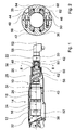
- a longitudinal section through a part of a preferred Screwdriver trained hand tool 10 shows figure 1.
- a housing 12 encloses a drive assembly 14 which a trained as a motor first drive unit 16, a designed as a transmission second drive unit 18, as Clutch, in particular Automatrastkupplung trained third Drive unit 20 and designed as a tool drive fourth drive unit 22 has.
- the drive units 16, 18, 20, 22 are along a longitudinal extent 52 of the drive assembly 14 arranged.
- the drive units 16, 18, 20, 22 have central axes 24, 26, 28, 30, which in the ideal case form a common central axis, but also, for example production-related, offset against each other can.
- a shaft 56 extends from the transmission formed second drive unit 18 for as a tool drive formed fourth drive unit 22.
- the drive units 16, 18, 20, 22 of the drive assembly 14 are substantially rigidly coupled with each other.
- a first, for damping at least axially directed vibrations provided vibration damping unit 32 is at a End face 38 of the drive motor designed as the first Drive unit 16 is arranged.
- a second, for damping at least radially directed vibrations provided vibration damping unit 34 is circumferentially on a circumference 40th around the second drive unit 18 designed as a transmission arranged.
- a third, for damping at least in the circumferential direction acting vibrations provided vibration damping unit 36 is formed in the region of the coupling provided third drive unit 20 and surrounds there Pin 42.
- the individual vibration damping units 32, 34, 36 are part of a vibration damping device.
- Figure 2 shows a cross section through an area with a in the tangential direction damping third vibration damping unit 36. Substantially equal parts basically numbered with the same reference numerals. Further can with regard to consistent features and functions Reference is made to the description of Figure 1.
- Two enclosing housing 12 forming housing halves 64, 66 are in a first bore 44 with a screw 48 and in a second bore 46 with a screw 50 together connected.
- a sleeve 62 formed as a coupling third drive unit 20 ( Figure 2) is on both sides of a Spigot 42 in the lower housing half 66 and a pin 68 arranged in the upper housing half 64. In the Center is an opening through which a shaft is passed can. Both pins 42, 68 are each a vibration damping unit 36 surrounded.
Abstract
Description
Die Erfindung geht aus von einer Handwerkzeugmaschine nach dem Oberbegriff des Anspruchs 1.The invention is based on a hand tool the preamble of claim 1.
Aus der DE 40 00 861 C2 ist eine Handwerkzeugmaschine mit einem Motorgehäuse bekannt, das auf der einer Werkzeugaufnahme abgewandten Seite der Schlagbohrmaschine von einem Hüllgehäuse umgeben ist. An das Hüllgehäuse ist ein Handgriff mit einem Griffelement angeformt. Das Hüllgehäuse ist über eine Schwingungsdämpfungsvorrichtung mit dem Motorgehäuse verbunden, das gleichzeitig ein Trägerelement für den Handgriff bildet. Die Schwingungsdämpfungsvorrichtung weist mehrere elastische Schwingungsdämpfungseinheiten aus Gummi auf, über die das Hüllgehäuse, und damit das Griffelement, vom Motorgehäuse schwingungsmäßig entkoppelt ist. From DE 40 00 861 C2 is a hand tool with a Motor housing known on the one tool holder opposite side of the hammer drill from a shell is surrounded. To the casing is a handle with a Handle element molded. The casing is over a Vibration damping device connected to the motor housing, at the same time a support element for the handle forms. The vibration damping device has a plurality of elastic Rubber vibration damping units, over the shell, and thus the handle, from the motor housing vibrationally decoupled.
Die Erfindung geht aus von einer Handwerkzeugmaschine mit einem Gehäuse, in dem Antriebseinheiten angeordnet sind, wobei im Gehäuse zumindest eine Schwingungsdämpfungsvorrichtung vorgesehen ist.The invention relates to a hand tool with a Housing, are arranged in the drive units, wherein in the housing at least one vibration damping device is provided.
Es wird vorgeschlagen, dass eine Antriebsanordnung mit zumindest einer Antriebseinheit durch die Schwingungsdämpfungsvorrichtung gegenüber dem Gehäuse in axialer, radialer und Umfangsrichtung entkoppelt ist. Etwaige Gerätevibrationen können in allen drei Schwingungsrichtungen abgefangen werden. Zugleich besteht die Möglichkeit, einen Versatz von Mittelachsen von Antriebseinheiten in der Antriebsanordnung auszugleichen. Sowohl Wirkungsweise als auch Handhabung der Handwerkzeugmaschine bleiben unbeeinflusst.It is proposed that a drive arrangement with at least a drive unit by the vibration damping device relative to the housing in the axial, radial and circumferential direction is decoupled. Any device vibrations can be intercepted in all three directions of vibration. At the same time there is the possibility of an offset of central axes to compensate for drive units in the drive assembly. Both mode of action and handling of the Hand tool remain unaffected.
Umfasst die Antriebsanordnung entlang einer Längserstreckung zumindest einen Antriebsmotor und/oder ein Getriebe und/oder eine Kupplung und/oder einen Werkzeugantrieb, können geeignete Schwingungsdämpfungseinheiten zur Dämpfung von für die verschiedenen Antriebseinheiten spezifischen Schwingungsrichtungen an unterschiedlichen Antriebseinheiten gezielt platziert werden. Vorteilhaft kann ein etwaiger Versatz von Mittelachsen der Antriebseinheiten, die in einer starren Antriebsanordnung zusammengefasst sind, kostengünstig ausgeglichen werden, da auf zusätzliche Ausgleichselemente oder eine aufwändige und teure Innenkontur im Gehäuse verzichtet werden kann. Includes the drive assembly along a longitudinal extent at least one drive motor and / or a transmission and / or a coupling and / or a tool drive, suitable Vibration damping units for damping of the different drive units specific vibration directions purposefully placed on different drive units become. Advantageously, a possible offset of central axes the drive units in a rigid drive assembly are summarized, cost-effectively balanced be there on additional compensation elements or one elaborate and expensive interior contour in the housing are dispensed with can.
In einer bevorzugten Ausgestaltung weist die Schwingungsdämpfungsvorrichtung eine erste Schwingungsdämpfungseinheit zur Dämpfung zumindest axial gerichteter Schwingungen auf, wobei bevorzugt die erste Schwingungsdämpfungseinheit an einer Stirnseite eines an einer Stirnseite der Antriebsanordnung angeordneten Antriebsmotors vorgesehen ist. Dadurch kann die Antriebsanordnung in axialer Richtung gelagert werden und gleichzeitig Schwingungsenergie in axialer Richtung vom Gehäuse ferngehalten werden. Zugleich kann die erste Schwingungsdämpfungseinheit einen etwaigen Versatz der Mittelachsen der Antriebseinheiten axial, d.h. in Längsrichtung, ausgleichen. Die zweite Schwingungsdämpfungseinheit kann die Antriebsanordnung auch in radialer Richtung abstützen. Die Schwingungsdämpfungseinheit ist vorzugsweise ein Gummielement oder kann alternativ eine Druckfeder, eine Schraubendruckfeder oder ein dem Fachmann sinnvoll erscheinendes Element sein.In a preferred embodiment, the vibration damping device a first vibration damping unit for Damping at least axially directed vibrations, wherein Preferably, the first vibration damping unit on a Front side of a front end of the drive assembly arranged drive motor is provided. This allows the Drive arrangement can be stored in the axial direction and simultaneously vibration energy in the axial direction of the housing be kept away. At the same time, the first vibration damping unit a possible offset of the central axes the drive units axially, i. in the longitudinal direction, compensate. The second vibration damping unit may be the drive arrangement also support in the radial direction. The Vibration damping unit is preferably a rubber element or alternatively, a compression spring, a helical compression spring or an element which appears reasonable to the person skilled in the art be.
In einer günstigen Anordnung umfasst die Schwingungsdämpfungsvorrichtung eine zweite Schwingungsdämpfungseinheit zur Dämpfung zumindest radial gerichteter Schwingungen, wobei bevorzugt die zweite Schwingungsdämpfungseinheit umfangseitig um ein Getriebe der Antriebsanordnung angeordnet ist. Damit können Schwingungen der Antriebsanordnung in radialer Richtung vom Gehäuse ferngehalten werden. Zugleich kann die zweite Schwingungsdämpfungseinheit einen etwaigen radialen Versatz der Mittelachsen der Antriebseinheiten ausgleichen.In a favorable arrangement, the vibration damping device comprises a second vibration damping unit for Attenuation of at least radially directed vibrations, being preferred the second vibration damping unit peripherally is arranged around a transmission of the drive assembly. In order to can vibrations of the drive assembly in the radial direction be kept away from the housing. At the same time, the second Vibration damping unit a possible radial offset compensate for the center axes of the drive units.
Ferner ist es günstig, wenn die Schwingungsdämpfungsvorrichtung eine dritte Schwingungsdämpfungseinheit zur Dämpfung von Schwingungen zumindest in Umfangsrichtung umfasst, wobei die dritte Schwingungsdämpfungseinheit im Bereich einer Kupplung der Antriebsanordnung vorgesehen ist. Damit können Schwingungen der Antriebsanordnung in Umfangsrichtung vom Gehäuse ferngehalten werden. Die dritte Schwingungsdämpfungseinheit kann gleichzeitig einen etwaigen Winkelversatz der Mittelachsen der Antriebseinheiten ausgleichen. Die dritte Schwingungsdämpfungseinheit kann die Antriebsanordnung auch in radialer Richtung abstützen.Furthermore, it is favorable if the vibration damping device a third vibration damping unit for damping Vibrations comprises at least in the circumferential direction, wherein the third vibration damping unit in the region of a clutch the drive arrangement is provided. This can be vibrations the drive assembly in the circumferential direction of the housing be kept away. The third vibration damping unit can simultaneously a possible angular offset of the central axes compensate the drive units. The third vibration damping unit can the drive assembly in the radial Support the direction.
Vorzugsweise sind die Schwingungsdämpfungseinheiten aus einem weichen, gummiartigen Material gebildet. Es sind auch andere Arten von schwingungsabsorbierenden Materialien denkbar, etwa Verbundkörper, Federn und dergleichen. Die Erfindung kann unabhängig von der Art der Verbindung der Gehäuseteile miteinander eingesetzt werden. Ebenso kann eine einzige Schwingungsdämpfungseinheit entsprechend ausgebildet oder ausgelegt sein, um unterschiedliche Schwingungsrichtungen zu dämpfen.Preferably, the vibration damping units are made of one soft, rubbery material formed. There are others too Types of vibration absorbing materials conceivable, such as Composite bodies, springs and the like. The invention can be independent on the nature of the connection of the housing parts with each other be used. Likewise, a single vibration damping unit designed or designed accordingly be to dampen different directions of vibration.
Bildet die Antriebsanordnung eine im Wesentlichen starre Einheit, kann mit einer geeigneten Verteilung der Schwingungsdämpfungseinheiten der Schwingungsdämpfungsvorrichtung eine vorteilhafte Lagerung der Antriebsanordnung ausschließlich durch die Schwingungsdämpfungsvorrichtung realisiert werden. Die Antriebsanordnung kann dadurch praktisch vollständig von dem Gehäuse entkoppelt werden. Vorzugsweise liegt die Antriebsanordnung nur über die Schwingungsdämpfungsvorrichtung an dem Gehäuse an. Eine gute Handhabung und Wirkungsweise der Handwerkzeugmaschine bleibt erhalten.If the drive arrangement forms a substantially rigid unit, can with a suitable distribution of the vibration damping units the vibration damping device a advantageous storage of the drive assembly exclusively be realized by the vibration damping device. The drive assembly can thereby practically completely from be decoupled from the housing. Preferably, the drive assembly is located only via the vibration damping device on the housing. Good handling and operation of the Hand tool remains.
Die erfindungsgemäße Lösung kann bei verschiedenen, dem Fachmann als sinnvoll erscheinenden Werkzeugmaschinen angewendet werden, jedoch besonders vorteilhaft bei elektrisch angetriebenen Handwerkzeugmaschinen, wie beispielsweise Schlagbohrmaschinen, Schabern, Sägen, Schraubern und insbesondere Winkelschleifern usw., die aufgrund ihrer meist freien Beweglichkeit und häufig hohen Antriebsdrehzahlen grundsätzlich zu Schwingungen neigen. Sehr günstig ist der Einsatz bei solchen Handwerkzeugmaschinen, bei denen kein zusätzlicher Handgriff oder keine zusätzlichen Haltemöglichkeiten außerhalb des Bereichs der umhüllenden Geometrie vorgesehen sind, sondern deren Gehäuse selbst einen Handgriff darstellt, wie beispielsweise bei handgeführten Schraubern, Industrieschraubern mit geregeltem Abschaltmoment und dergleichen.The solution according to the invention can be carried out by various persons skilled in the art applied as meaningful machine tools be, but particularly advantageous in electrically driven Hand tool machines, such as impact drills, Scrapers, saws, screwdrivers and in particular angle grinders etc., due to their mostly free mobility and often high drive speeds in principle too Tend to oscillate. Very favorable is the use in such Hand tool machines, where no additional handle or no extra hold outside the area the enveloping geometry are provided, but their Housing itself represents a handle, such as with hand-held screwdrivers, industrial screwdrivers with controlled shutdown and the like.
Weitere Vorteile ergeben sich aus der folgenden Zeichnungsbeschreibung. In der Zeichnung ist ein Ausführungsbeispiel der Erfindung dargestellt. Die Zeichnung, die Beschreibung und die Ansprüche enthalten zahlreiche Merkmale in Kombination. Der Fachmann wird die Merkmale zweckmäßigerweise auch einzeln betrachten und zu sinnvollen weiteren Kombinationen zusammenfassen.Further advantages emerge from the following description of the drawing. In the drawing, an embodiment of the Invention shown. The drawing, the description and The claims contain numerous features in combination. The person skilled in the art expediently also individually consider and summarize to meaningful further combinations.
Es zeigen:
- Fig. 1
- einen Längsschnitt durch einen bevorzugten handgeführten Schrauber,
- Fig. 2
- einen Querschnitt durch einen Bereich mit einer in tangentialer Richtung dämpfenden Schwingungsdämpfungseinheit.
- Fig. 1
- a longitudinal section through a preferred hand-held screwdriver,
- Fig. 2
- a cross section through an area with a damping in the tangential direction vibration damping unit.
Einen Längsschnitt durch einen Teil einer als bevorzugten
Schrauber ausgebildeten Handwerkzeugmaschine 10 zeigt Figur
1. Ein Gehäuse 12 umschließt eine Antriebsanordnung 14, die
eine als Motor ausgebildete erste Antriebseinheit 16, eine
als Getriebe ausgebildete zweite Antriebseinheit 18, eine als
Kupplung, insbesondere Überrastkupplung, ausgebildete dritte
Antriebseinheit 20 sowie eine als Werkzeugantrieb ausgebildete
vierte Antriebseinheit 22 aufweist. Die Antriebseinheiten
16, 18, 20, 22 sind entlang einer Längserstreckung 52 der Antriebsanordnung
14 angeordnet. Die Antriebseinheiten 16, 18,
20, 22 weisen Mittelachsen 24, 26, 28, 30 auf, die im Idealfall
eine gemeinsame Mittelachse bilden, jedoch auch, beispielsweise
produktionsbedingt, gegeneinander versetzt sein
können. Eine Welle 56 erstreckt sich von der als Getriebe
ausgebildeten zweiten Antriebseinheit 18 zur als Werkzeugantrieb
ausgebildeten vierten Antriebseinheit 22. Die Antriebseinheiten
16, 18, 20, 22 der Antriebsanordnung 14 sind im Wesentlichen
starr miteinander gekoppelt.A longitudinal section through a part of a preferred
Screwdriver trained
Eine erste, zur Dämpfung zumindest axial gerichteter Schwingungen
vorgesehene Schwingungsdämpfungseinheit 32, ist an einer
Stirnseite 38 der als Antriebsmotor ausgebildeten ersten
Antriebseinheit 16 angeordnet. Eine zweite, zur Dämpfung zumindest
radial gerichteter Schwingungen vorgesehene Schwingungsdämpfungseinheit
34 ist umfangseitig an einem Umfang 40
um die als Getriebe ausgebildete zweite Antriebseinheit 18
angeordnet. Eine dritte, zur Dämpfung zumindest in Umfangsrichtung
wirkender Schwingungen vorgesehene Schwingungsdämpfungseinheit
36 ist im Bereich der als Kupplung ausgebildeten
dritten Antriebseinheit 20 vorgesehen und umgibt dort einen
Zapfen 42. Die einzelnen Schwingungsdämpfungseinheiten 32,
34, 36 sind Bestandteil einer Schwingungsdämpfungsvorrichtung.A first, for damping at least axially directed vibrations
provided
An die als Kupplung ausgebildete dritte Antriebseinheit 20
schließt sich die als Werkzeugantrieb ausgebildete vierte Antriebseinheit
22 an. Diese weist ein Winkelgetriebe 58 auf.
Insgesamt liegt die Antriebsanordnung 14 nur über die Schwingungsdämpfungseinheiten
32, 34, 36 an dem Gehäuse 12 an. Ferner
ist noch eine Schwingungsdämpfungseinheit 60 vorgesehen,
die eine Hülse 62 der als Kupplung ausgebildeten dritten Antriebseinheit
20 umgibt.To the trained as a clutch third drive unit 20th
closes formed as a tool drive
Weiterhin sind noch Schrauben 48, 50 im Bereich der als Kupplung
ausgebildeten dritten Antriebseinheit 20 sowie eine Reihe
weiterer nicht näher bezeichneter Schrauben vorgesehen,
die Gehäusehälften des Gehäuses 12 miteinander verbinden.Furthermore, there are still screws 48, 50 in the area of the clutch
formed
Figur 2 zeigt einen Querschnitt durch einen Bereich mit einer
in tangentialer Richtung dämpfenden dritten Schwingungsdämpfungseinheit
36. Im Wesentlichen gleich bleibende Teile sind
grundsätzlich mit den gleichen Bezugszeichen beziffert. Ferner
kann bezüglich gleich bleibender Merkmale und Funktionen
auf die Beschreibung der Figur 1 verwiesen werden. Figure 2 shows a cross section through an area with a
in the tangential direction damping third
Zwei ein umhüllendes Gehäuse 12 bildende Gehäusehälften 64,
66 sind in einer ersten Bohrung 44 mit einer Schraube 48 und
in einer zweiten Bohrung 46 mit einer Schraube 50 miteinander
verbunden. Eine Hülse 62 einer als Kupplung ausgebildeten
dritten Antriebseinheit 20 (Figur 2) ist zu beiden Seiten eines
Zapfens 42 in der unteren Gehäusehälfte 66 und eines Zapfens
68 in der oberen Gehäusehälfte 64 angeordnet. In der
Mitte ist eine Öffnung, durch die eine Welle geführt werden
kann. Beide Zapfen 42, 68 sind von je einer Schwingungsdämpfungseinheit
36 umgeben. Two enclosing
- 1010
- HandwerkzeugmaschineHand tool
- 1212
- Gehäusecasing
- 1414
- Antriebsanordnungdrive arrangement
- 1616
- Antriebseinheitdrive unit
- 1818
- Antriebseinheitdrive unit
- 2020
- Antriebseinheitdrive unit
- 2222
- Antriebseinheitdrive unit
- 2424
- Mittelachsecentral axis
- 2626
- Mittelachsecentral axis
- 2828
- Mittelachsecentral axis
- 3030
- Mittelachsecentral axis
- 3232
- SchwingungsdämpfungseinheitVibration damping unit
- 3434
- SchwingungsdämpfungseinheitVibration damping unit
- 3636
- SchwingungsdämpfungseinheitVibration damping unit
- 3838
- Stirnseitefront
- 4040
- Umfangscope
- 4242
- Zapfenspigot
- 4444
- Bohrungdrilling
- 4646
- Bohrungdrilling
- 4848
- Schraubescrew
- 5050
- Schraubescrew
- 5252
- Längserstreckunglongitudinal extension
- 5656
- Wellewave
- 5858
- Winkelgetriebeangle gear
- 6060
- SchwingungsdämpfungseinheitVibration damping unit
- 6262
- Hülseshell
- 6464
- Gehäusehälftehousing half
- 6666
- Gehäusehälftehousing half
- 6868
- Zapfenspigot
Claims (10)
Applications Claiming Priority (2)
| Application Number | Priority Date | Filing Date | Title |
|---|---|---|---|
| DE10361812 | 2003-12-30 | ||
| DE2003161812 DE10361812A1 (en) | 2003-12-30 | 2003-12-30 | Hand tool |
Publications (2)
| Publication Number | Publication Date |
|---|---|
| EP1550532A1 true EP1550532A1 (en) | 2005-07-06 |
| EP1550532B1 EP1550532B1 (en) | 2008-10-08 |
Family
ID=34559789
Family Applications (1)
| Application Number | Title | Priority Date | Filing Date |
|---|---|---|---|
| EP20040105721 Expired - Fee Related EP1550532B1 (en) | 2003-12-30 | 2004-11-12 | Hand tool with vibration damping |
Country Status (3)
| Country | Link |
|---|---|
| EP (1) | EP1550532B1 (en) |
| CN (1) | CN100457400C (en) |
| DE (2) | DE10361812A1 (en) |
Cited By (3)
| Publication number | Priority date | Publication date | Assignee | Title |
|---|---|---|---|---|
| WO2008006635A1 (en) * | 2006-07-10 | 2008-01-17 | Robert Bosch Gmbh | Hand-held machine tool |
| JP2011036924A (en) * | 2009-08-06 | 2011-02-24 | Makita Corp | Power tool |
| CN105666393A (en) * | 2015-12-31 | 2016-06-15 | 宁波中旺工具有限公司 | Electric screw driver |
Families Citing this family (4)
| Publication number | Priority date | Publication date | Assignee | Title |
|---|---|---|---|---|
| DE102008001268A1 (en) * | 2008-04-18 | 2009-10-22 | Robert Bosch Gmbh | Plug arrangement in a machine tool, in particular in a hand tool |
| WO2010151205A1 (en) * | 2009-06-25 | 2010-12-29 | Atlas Copco Construction Tools Ab | Hand-held demolition tool |
| SE540933C2 (en) | 2016-12-29 | 2018-12-27 | Husqvarna Ab | Improved handheld power tool |
| CN209699020U (en) * | 2018-06-05 | 2019-11-29 | 南京德朔实业有限公司 | Hand-hold power tool and swing class tool |
Citations (5)
| Publication number | Priority date | Publication date | Assignee | Title |
|---|---|---|---|---|
| GB2154497A (en) * | 1984-02-18 | 1985-09-11 | Bosch Gmbh Robert | Hand machine tool, particularly hammer drill or percussion drill |
| US5322131A (en) * | 1993-05-20 | 1994-06-21 | Chicago Pneumatic Tool Company | Vibration-reduced pneumatic tool |
| US6286610B1 (en) * | 1997-07-15 | 2001-09-11 | Wacker-Werke Gmbh & Co. Kg | Percussion and/or drill hammer with oscillation damping |
| US6318479B1 (en) * | 1999-10-01 | 2001-11-20 | Chicago Pneumatic Tool Company | Vibration isolated impact wrench |
| US20030006051A1 (en) * | 2001-06-21 | 2003-01-09 | Harald Schmitzer | Percussion electrical hand-held power tool with active vibration damping |
Family Cites Families (2)
| Publication number | Priority date | Publication date | Assignee | Title |
|---|---|---|---|---|
| CN2138694Y (en) * | 1991-11-11 | 1993-07-21 | 西安石油学院 | Follower active damper in mining field |
| WO2002083369A1 (en) * | 2001-04-11 | 2002-10-24 | Robert Bosch Gmbh | Hand tool machine comprising a vibration-dampened handle |
-
2003
- 2003-12-30 DE DE2003161812 patent/DE10361812A1/en not_active Withdrawn
-
2004
- 2004-11-12 DE DE200450008196 patent/DE502004008196D1/en active Active
- 2004-11-12 EP EP20040105721 patent/EP1550532B1/en not_active Expired - Fee Related
- 2004-12-29 CN CNB2004101048292A patent/CN100457400C/en not_active Expired - Fee Related
Patent Citations (5)
| Publication number | Priority date | Publication date | Assignee | Title |
|---|---|---|---|---|
| GB2154497A (en) * | 1984-02-18 | 1985-09-11 | Bosch Gmbh Robert | Hand machine tool, particularly hammer drill or percussion drill |
| US5322131A (en) * | 1993-05-20 | 1994-06-21 | Chicago Pneumatic Tool Company | Vibration-reduced pneumatic tool |
| US6286610B1 (en) * | 1997-07-15 | 2001-09-11 | Wacker-Werke Gmbh & Co. Kg | Percussion and/or drill hammer with oscillation damping |
| US6318479B1 (en) * | 1999-10-01 | 2001-11-20 | Chicago Pneumatic Tool Company | Vibration isolated impact wrench |
| US20030006051A1 (en) * | 2001-06-21 | 2003-01-09 | Harald Schmitzer | Percussion electrical hand-held power tool with active vibration damping |
Cited By (5)
| Publication number | Priority date | Publication date | Assignee | Title |
|---|---|---|---|---|
| WO2008006635A1 (en) * | 2006-07-10 | 2008-01-17 | Robert Bosch Gmbh | Hand-held machine tool |
| JP2011036924A (en) * | 2009-08-06 | 2011-02-24 | Makita Corp | Power tool |
| EP2281663A3 (en) * | 2009-08-06 | 2011-07-13 | Makita Corporation | Power tools |
| US8413743B2 (en) | 2009-08-06 | 2013-04-09 | Makita Corporation | Power tools |
| CN105666393A (en) * | 2015-12-31 | 2016-06-15 | 宁波中旺工具有限公司 | Electric screw driver |
Also Published As
| Publication number | Publication date |
|---|---|
| DE502004008196D1 (en) | 2008-11-20 |
| EP1550532B1 (en) | 2008-10-08 |
| DE10361812A1 (en) | 2005-07-28 |
| CN1636681A (en) | 2005-07-13 |
| CN100457400C (en) | 2009-02-04 |
Similar Documents
| Publication | Publication Date | Title |
|---|---|---|
| EP1940593B1 (en) | Electric machine tool | |
| EP1965952B1 (en) | Manual machine tool having a drivetrain and a decoupling unit | |
| EP1335815B1 (en) | Grip handle for hand-held machine tool | |
| EP2512752B1 (en) | Hand-power tool | |
| WO2008155151A1 (en) | Machine hand tool housing unit | |
| EP2119537A1 (en) | Electric hand tool | |
| DE102007037047A1 (en) | Auxiliary handle device | |
| EP1752259B1 (en) | Electric hand tool | |
| DE102005000199A1 (en) | Hand tool with ratchet impact mechanism | |
| WO2008006635A1 (en) | Hand-held machine tool | |
| EP1550532B1 (en) | Hand tool with vibration damping | |
| DE3922552A1 (en) | Electrically-driven hand tool - incorporates vibration-damping components between spindle and motor | |
| DE102017211779A1 (en) | Hand machine tool device | |
| DE102012222639A1 (en) | Percussion device for use in e.g. drilling and/or chipping hammer, has fixing element which extends along circumferential direction around guiding element and tool receiving element, for force-locking connection | |
| DE202016103701U1 (en) | Hand machine tool device | |
| WO2004085118A1 (en) | Electric hand tool | |
| DE10236135A1 (en) | Portable electric hand tool e.g. drill and chisel hammer, provided with handgrip which is spring-loaded for movement relative to tool housing for providing vibration damping | |
| DE102012203758A1 (en) | Hand machine tool device | |
| DE10348974A1 (en) | Vibration damped handgrip especially for a power hand tool has a cylindrical outer grip positioned onto a support grip via fluid damping inserts especially gel dampers | |
| EP3274132B1 (en) | Hand-held power tool | |
| DE10348973A1 (en) | Vibration damped handgrip especially for a power hand tool has a cylindrical outer grip positioned onto a support grip via elastomer damping inserts | |
| DE102017211773A1 (en) | Hand machine tool device | |
| DE2912718A1 (en) | TOOL DRIVEN BY COMPRESSED AIR | |
| DE102007031983A1 (en) | Hand-held machine tool for driving bit, comprises drive train, which has drive side associated with drive unit and driven side associated with tool holder | |
| DE102019205827A1 (en) | Hand machine tool with a securing element for a shaft |
Legal Events
| Date | Code | Title | Description |
|---|---|---|---|
| PUAI | Public reference made under article 153(3) epc to a published international application that has entered the european phase |
Free format text: ORIGINAL CODE: 0009012 |
|
| AK | Designated contracting states |
Kind code of ref document: A1 Designated state(s): AT BE BG CH CY CZ DE DK EE ES FI FR GB GR HU IE IS IT LI LU MC NL PL PT RO SE SI SK TR |
|
| AX | Request for extension of the european patent |
Extension state: AL HR LT LV MK YU |
|
| 17P | Request for examination filed |
Effective date: 20060109 |
|
| AKX | Designation fees paid |
Designated state(s): DE FR GB SE |
|
| 17Q | First examination report despatched |
Effective date: 20060406 |
|
| GRAP | Despatch of communication of intention to grant a patent |
Free format text: ORIGINAL CODE: EPIDOSNIGR1 |
|
| GRAS | Grant fee paid |
Free format text: ORIGINAL CODE: EPIDOSNIGR3 |
|
| GRAA | (expected) grant |
Free format text: ORIGINAL CODE: 0009210 |
|
| AK | Designated contracting states |
Kind code of ref document: B1 Designated state(s): DE FR GB SE |
|
| REG | Reference to a national code |
Ref country code: GB Ref legal event code: FG4D Free format text: NOT ENGLISH |
|
| REF | Corresponds to: |
Ref document number: 502004008196 Country of ref document: DE Date of ref document: 20081120 Kind code of ref document: P |
|
| REG | Reference to a national code |
Ref country code: SE Ref legal event code: TRGR |
|
| PLBE | No opposition filed within time limit |
Free format text: ORIGINAL CODE: 0009261 |
|
| STAA | Information on the status of an ep patent application or granted ep patent |
Free format text: STATUS: NO OPPOSITION FILED WITHIN TIME LIMIT |
|
| 26N | No opposition filed |
Effective date: 20090709 |
|
| PGFP | Annual fee paid to national office [announced via postgrant information from national office to epo] |
Ref country code: GB Payment date: 20121122 Year of fee payment: 9 Ref country code: SE Payment date: 20121122 Year of fee payment: 9 |
|
| PGFP | Annual fee paid to national office [announced via postgrant information from national office to epo] |
Ref country code: FR Payment date: 20121217 Year of fee payment: 9 |
|
| PGFP | Annual fee paid to national office [announced via postgrant information from national office to epo] |
Ref country code: DE Payment date: 20130124 Year of fee payment: 9 |
|
| REG | Reference to a national code |
Ref country code: SE Ref legal event code: EUG |
|
| GBPC | Gb: european patent ceased through non-payment of renewal fee |
Effective date: 20131112 |
|
| REG | Reference to a national code |
Ref country code: FR Ref legal event code: ST Effective date: 20140731 |
|
| REG | Reference to a national code |
Ref country code: DE Ref legal event code: R119 Ref document number: 502004008196 Country of ref document: DE Effective date: 20140603 |
|
| PG25 | Lapsed in a contracting state [announced via postgrant information from national office to epo] |
Ref country code: SE Free format text: LAPSE BECAUSE OF NON-PAYMENT OF DUE FEES Effective date: 20131113 Ref country code: DE Free format text: LAPSE BECAUSE OF NON-PAYMENT OF DUE FEES Effective date: 20140603 |
|
| PG25 | Lapsed in a contracting state [announced via postgrant information from national office to epo] |
Ref country code: FR Free format text: LAPSE BECAUSE OF NON-PAYMENT OF DUE FEES Effective date: 20131202 Ref country code: GB Free format text: LAPSE BECAUSE OF NON-PAYMENT OF DUE FEES Effective date: 20131112 |