EP2839731B1 - Machine de récolte de fourrage - Google Patents
Machine de récolte de fourrage Download PDFInfo
- Publication number
- EP2839731B1 EP2839731B1 EP14175913.4A EP14175913A EP2839731B1 EP 2839731 B1 EP2839731 B1 EP 2839731B1 EP 14175913 A EP14175913 A EP 14175913A EP 2839731 B1 EP2839731 B1 EP 2839731B1
- Authority
- EP
- European Patent Office
- Prior art keywords
- support arm
- work
- respect
- configuration
- work tool
- Prior art date
- Legal status (The legal status is an assumption and is not a legal conclusion. Google has not performed a legal analysis and makes no representation as to the accuracy of the status listed.)
- Active
Links
Images


Classifications
-
- A—HUMAN NECESSITIES
- A01—AGRICULTURE; FORESTRY; ANIMAL HUSBANDRY; HUNTING; TRAPPING; FISHING
- A01B—SOIL WORKING IN AGRICULTURE OR FORESTRY; PARTS, DETAILS, OR ACCESSORIES OF AGRICULTURAL MACHINES OR IMPLEMENTS, IN GENERAL
- A01B63/00—Lifting or adjusting devices or arrangements for agricultural machines or implements
- A01B63/14—Lifting or adjusting devices or arrangements for agricultural machines or implements for implements drawn by animals or tractors
- A01B63/24—Tools or tool-holders adjustable relatively to the frame
- A01B63/32—Tools or tool-holders adjustable relatively to the frame operated by hydraulic or pneumatic means without automatic control
-
- A—HUMAN NECESSITIES
- A01—AGRICULTURE; FORESTRY; ANIMAL HUSBANDRY; HUNTING; TRAPPING; FISHING
- A01B—SOIL WORKING IN AGRICULTURE OR FORESTRY; PARTS, DETAILS, OR ACCESSORIES OF AGRICULTURAL MACHINES OR IMPLEMENTS, IN GENERAL
- A01B73/00—Means or arrangements to facilitate transportation of agricultural machines or implements, e.g. folding frames to reduce overall width
- A01B73/02—Folding frames
- A01B73/04—Folding frames foldable about a horizontal axis
- A01B73/044—Folding frames foldable about a horizontal axis the axis being oriented in a longitudinal direction
-
- A—HUMAN NECESSITIES
- A01—AGRICULTURE; FORESTRY; ANIMAL HUSBANDRY; HUNTING; TRAPPING; FISHING
- A01B—SOIL WORKING IN AGRICULTURE OR FORESTRY; PARTS, DETAILS, OR ACCESSORIES OF AGRICULTURAL MACHINES OR IMPLEMENTS, IN GENERAL
- A01B63/00—Lifting or adjusting devices or arrangements for agricultural machines or implements
- A01B63/14—Lifting or adjusting devices or arrangements for agricultural machines or implements for implements drawn by animals or tractors
- A01B63/24—Tools or tool-holders adjustable relatively to the frame
-
- A—HUMAN NECESSITIES
- A01—AGRICULTURE; FORESTRY; ANIMAL HUSBANDRY; HUNTING; TRAPPING; FISHING
- A01B—SOIL WORKING IN AGRICULTURE OR FORESTRY; PARTS, DETAILS, OR ACCESSORIES OF AGRICULTURAL MACHINES OR IMPLEMENTS, IN GENERAL
- A01B73/00—Means or arrangements to facilitate transportation of agricultural machines or implements, e.g. folding frames to reduce overall width
- A01B73/02—Folding frames
-
- A—HUMAN NECESSITIES
- A01—AGRICULTURE; FORESTRY; ANIMAL HUSBANDRY; HUNTING; TRAPPING; FISHING
- A01D—HARVESTING; MOWING
- A01D78/00—Haymakers with tines moving with respect to the machine
- A01D78/001—Side-delivery rakes
-
- A—HUMAN NECESSITIES
- A01—AGRICULTURE; FORESTRY; ANIMAL HUSBANDRY; HUNTING; TRAPPING; FISHING
- A01D—HARVESTING; MOWING
- A01D78/00—Haymakers with tines moving with respect to the machine
- A01D78/08—Haymakers with tines moving with respect to the machine with tine-carrying rotary heads or wheels
- A01D78/14—Haymakers with tines moving with respect to the machine with tine-carrying rotary heads or wheels the tines rotating about a substantially horizontal axis
-
- A—HUMAN NECESSITIES
- A01—AGRICULTURE; FORESTRY; ANIMAL HUSBANDRY; HUNTING; TRAPPING; FISHING
- A01D—HARVESTING; MOWING
- A01D84/00—Haymakers not provided for in a single one of groups A01D76/00 - A01D82/00
-
- A—HUMAN NECESSITIES
- A01—AGRICULTURE; FORESTRY; ANIMAL HUSBANDRY; HUNTING; TRAPPING; FISHING
- A01D—HARVESTING; MOWING
- A01D87/00—Loaders for hay or like field crops
- A01D87/02—Loaders for hay or like field crops with conveyor belts or conveyor chains, with or without pick-up means
Definitions
- a machine of this type is known from the document US 8 186 138 B2 .
- This machine is of the type known under the name of "Merger”.
- This machine has a frame designed to be hitched to the rear of a tractor, and supported on the ground by wheels in its rear part.
- On at least one lateral side of the frame is articulated a support arm carrying a working tool.
- This support arm can be placed in a working configuration in which the working tool extends perpendicularly to the direction of travel and substantially horizontally.
- the working tool comprises a toothed rotor which, during work, extends perpendicularly to the direction of travel and picks up the plants present on the ground.
- Plants collected are moved backwards by the rotor, towards the a conveyor belt that moves the plants perpendicularly to the direction of travel, towards a lateral side of the work tool.
- the working tool is, in its rear part, connected to a support by means of an axis oriented horizontally and parallel to the direction of advance when the support arm is in working configuration.
- This support is in turn connected to the support arm by means of a first connecting rod and a second connecting rod located under the first connecting rod.
- the first link is articulated to the support arm and the support by means of respective physical axes which are oriented horizontally and transversely to the direction of travel when the support arm is in working configuration.
- the first and second links can move vertically relative to the support arm in the working configuration, so that the work tool can, in its entirety, move upwards or downwards to follow a terrain with uneven profile.
- this displacement is only vertical.
- the distance, measured horizontally and perpendicular to the direction of travel, which separates the working tool from the frame remains constant.
- the plants can, after their mowing, be grouped in swaths whose width and spacing from one another vary according to the mowing and / or windrowing machines used.
- a case of use of the known machine consists in that the tractor and the machine overlap a first swath, so that the first swath passes between the wheels of the tractor and between the wheels of the machine, and in that the tool A second swath is parallel to the first swath and placed on one side of the tractor.
- This second windrow is deposited by the machine on or along the first windrow, or on or along a third windrow parallel to the second windrow and placed at a greater distance from the first windrow.
- the trajectory of the tractor and the machine is imposed by the fact that their respective wheels must not crush the first swath.
- this second windrow is taken up only partially by the working tool. The latter therefore leaves an unassassed fraction of the second windrow. A complete pickup the second windrow therefore requires additional machine passage, which increases field time and operating costs, and reduces productivity.
- the work tool splits the second swath in two parts increases the risk of plant stuffing within the work tool.
- the manner in which the second swath is redeposited on or along the first or third windrow is not modifiable, because it is imposed by the distance between the working tool and the frame whose wheels overlap the first swath.
- the appearance of the new windrow, obtained by the grouping of the second windrow and the first or third swath, is not always optimal depending on the nature of the plants and the meteorological conditions encountered.
- the known machine does not allow to change the transverse positioning of the work tool relative to the tractor. Therefore, it is not possible in particular to adjust the total width of the tractor-machine combination to work.
- the working tool is connected to the support arm concerned by means of a connecting device comprising a first arm and a second arm.
- the first arm extends substantially in the direction of advancement, from a first vertical axis of articulation to the support arm.
- the first arm carries a second arm by means of a second axis of articulation extending substantially in the direction of travel.
- This second arm extends transversely to the direction of travel and carries, at its end remote from the second axis, the frame of the working tool concerned.
- the second arm is telescopic so as to allow a transverse displacement of the work tool.
- This connecting device is complex and bulky because of the first and second arm which extend in respective different directions.
- the telescopic arrangement of the second arm is complicated and expensive.
- the second axis of articulation is subjected to considerable mechanical stresses. These come on the one hand from the vertical movement of the second arm relative to the first.
- efforts that the plants moved by the machine advancing in the field exert on the working tool generate a torsion torque around a vertical axis passing through the second axis of articulation. This torque is high because of the long length of the second transversely directed arm, which can cause rapid wear of the second axis.
- the present invention aims to provide an agricultural machine for harvesting plants that does not have the aforementioned drawbacks.
- the invention is characterized in that the connecting device comprises at least one arm oriented essentially in the advancement direction when the support arm is in working configuration, that this arm is articulated to the support arm around a first axis which is oriented transversely to the advancement direction and substantially horizontally when the support arm is in the working configuration, and that this arm can, by pivoting about this first axis, move vertically relative to the support arm in configuration of work, so that the working tool can move vertically relative to said support arm.
- the distance, measured horizontally and perpendicular to the direction of advance, which separates the working tool from the frame, can be adjusted to the different working conditions.
- the transverse positioning of the working tool relative to the tractor can be modified.
- the means make it possible to easily adjust the distance relative to the frame to which the plants harvested by the working tool are redeposited on the ground by the machine, especially in the form of a swath.
- the working tool of the machine according to the invention may in particular be intended for swathing plants on the ground.
- the means allow to place transversely the work tool at the appropriate distance from the frame to resume, in whole and in one go, a second swath placed on a side of the tractor.
- this second windrow can be redeposited by the machine optimally on or along the first swath, or on the along a third swath placed at a greater distance from the tractor, in order to obtain a new swath of larger volume.
- the means thus make it possible to adjust the width, the height and the general shape of this new swath according to the nature of the plants, the meteorological conditions and the processing capacity of the press or the forage harvester used thereafter for pick up this new swath. More generally, the means allow easy adjustment of the transverse overlap between the working widths, on the one hand of the working tool of a machine according to the invention coupled to the rear of a tractor, on the other hand a work unit at the front of the tractor. This advantage is of course addressed to a work tool and a work unit of the aforementioned type, but also to a work tool and a work unit for mowing plants.
- the connecting device allows the work tool to follow the regardless of the transverse position of the work tool relative to the frame.
- the monitoring of the terrain is advantageously obtained by the first vertical displacement of the working tool relative to the support arm.
- the support arm can remain stationary or at least substantially immobile, so that the suspended masses, moving during the first movement, are advantageously limited to the respective masses of the work tool and the device of link.
- the connecting device combining the functions of vertical displacement and transverse displacement of the working tool relative to the support arm, the technical means for articulating the support arm to the frame and to ensure the movements of the support arm relative to the frame , can be simplified and lightened.
- the support arm can remain stationary, or substantially immobile, relative to the frame when the support arm is in the working configuration.
- the support arm can be simplified and lightened, being formed by a single piece which does not include articulated and / or telescopic connections.
- the device for connecting the frame of the working tool to the support arm comprises an arm oriented essentially in the direction of advancement.
- the connecting device according to the invention can remain compact and lightweight. This compactness goes hand in hand with good ground control since at work, the arm can move vertically relative to the support arm, around the first transverse and substantially horizontal axis by which the arm is articulated to the support arm.
- the longitudinal orientation of the arm and the transverse orientation of the first axis allow these elements to withstand the longitudinal forces exerted on the working tool by displaced plants.
- the connecting device according to the invention, connecting the frame of the work tool to the support arm has improved durability.
- the means comprise a first actuator which makes it possible to move the working tool relative to the support arm, transversely to the advancement direction, between a first position transverse to the support arm, in which the inner lateral end of the working tool is brought closer to a first vertical median plane of the frame, and a second transverse position relative to the support arm, wherein this inner lateral end is remote from this first median vertical plane.
- the width of the machine is reduced.
- the inner lateral end of the working tool placed in this first transverse position is located in the extension of the rear axle of the tractor. The working tool can then act on plants present on the ground and located at the rear of the tractor.
- the work tool can then take up a windrow passing between the wheels of the tractor to, for example, move it towards the outer lateral end of the tractor. the work tool.
- the inner lateral end is for example located substantially in the extension of the rear wheel of the tractor located on the same side as that where the working tool extends relative to the frame of the machine. This working tool can thus act on plants located on this side of the tractor, whether it is a working tool for windrowing or mowing these plants.
- a working tool intended to swath plants can pick up a lateral windrow placed on this side of the tractor, in order to redeposit it in the form a windrow, for example more or less in the center of the machine.
- a working tool intended to mow can, in this second transverse position, mow plants present on said side of the tractor and group them into a windrow lateral or more or less central with respect to the machine.
- the work tool may have some overlap with a work unit placed at the front of the tractor.
- the machine comprises two working tools each articulated to the frame by means of a respective support arm located on a respective side of the frame.
- the means for moving each work tool thus allow adjustment of the total working width of the machine.
- the means allow to space more or less these tools working from one another to adjust the width of a windrow formed in the center of the machine by at least one of these tools. job.
- the means allow adjustment of the overlap between the respective working widths of the working tools of a machine according to the invention hitched to the rear of a tractor, and the working width of a work unit placed at the front of the tractor.
- each support arm when each support arm is in its respective working configuration and at least one of the working tools is in the second transverse position relative to the corresponding support arm, the lateral ends of these working tools are clearly spaced from each other perpendicular to the direction of travel (A), and that when each support arm is in its respective working configuration and that each work tool is located in the first transverse position relative to the corresponding support arm, the inner lateral ends of these working tools are juxtaposed.
- the first transverse position allows the machine to act on a continuous width of plants.
- Working tools for windrowing machines can thus pick up a continuous width of plants, for example mowed or faded plants spread out on the ground, and place them in a swath on the left or right side of the machine.
- the second transversal position allows each work tool to act on plants distributed on the left and right of the machine.
- Work tools for windrowing can thus form a central windrow deposited between the two working tools, from plants collected by each respective work tool, for example from two lateral swaths which are each taken up by a respective work tool.
- the machine (1) is an agricultural machine for harvesting plants, particularly fodder.
- This machine (1) comprises a frame (2).
- a central beam (3) which has at its front end a coupling device (4) for attachment to a tractor (T) for moving the machine in a direction of advance (A).
- T tractor
- A direction of advance
- the central beam (3) extends in the direction of advance (A).
- the central beam (3) carries lateral uprights (5) which extend in the direction of the ground.
- the chassis (2) is supported on the ground by wheels (6). Each wheel (6) is carried by a respective lateral upright (5).
- the frame (2) is articulated at least one support arm (7) which is carried by a lateral upright (5).
- the support arm (7) is connected to this lateral upright (5) via a hinge element (8).
- This hinge element (8) is articulated to the lateral upright (5) by means of a first hinge axis (9).
- This hinge element (8) is arranged in front of the wheels (6).
- This first articulation axis (9) extends substantially in the direction of advance (A). This first articulation axis (9) is moreover substantially horizontal.
- the support arm (7) is articulated to the articulation element (8) by means of a second substantially vertical axis of articulation (10) when the machine is working.
- This second articulation axis (10) is substantially perpendicular to the first articulation axis (9).
- a third actuator (11) is disposed between the support arm (7) and the frame (2).
- This third actuator (11) for example a jack, is articulated to the frame (2) and the hinge member (8) and allows the latter to pivot about the first axis of articulation (9).
- a connecting rod (12) is further articulated to the frame (2) and the support arm (7). When the third actuator (11) is in the shortened position, the second hinge axis (10) is substantially vertical.
- the support arm (7) then extends in a working configuration in which it extends laterally with respect to the frame (2).
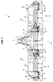
- This working configuration of the support arm (7) is particularly illustrated in FIGS. figures 1 , 3 and 5 .
- the support arm (7) extends further forward of the wheel (6) carried by the lateral upright (5) to which the support arm (7) is connected.
- the support arm (7) is substantially perpendicular to the direction of advance (A). It is moreover substantially horizontal.
- the third actuator (11) When the third actuator (11) is actuated at elongation, it pivots upwardly the hinge member (8) about the first hinge axis (9). Simultaneously, the support arm (7) pivots about the second hinge pin (10) due to the connecting rod (12) connecting it to the frame (2).
- the support arm (7) then pivots, from its working configuration, upwards and backwards relative to the chassis (2).
- the support arm (7) is placed in a transport configuration.
- This transport configuration of the support arm (7) is illustrated in FIG. figure 6 .
- the folded support arm (7) occupies a reduced space requirement according to a direction perpendicular to the direction of advance (A). This reduced bulk is obtained in particular by the fact that the support arm (7) then extends above the wheel (6) carried by the corresponding lateral upright (5).
- the support arm (7) extends substantially in the direction of advance (A). It extends substantially horizontally.
- the inner end (13) of the support arm (7) connected to the articulation element (8) is located in front of the wheel (6).
- the outer end (14) of the support arm (7) remote from its inner end (13) is placed behind the wheel (6).
- This folding kinematics of the support arm (7) allows, for transport, both a reduced width of the machine (1) and good handling thanks to a reduced wheelbase.
- the support arm (7) carries a working tool (15).
- the latter has an inner lateral end (16) and an outer lateral end (17).
- the working tool (15) is laterally, that is to say transversely to the direction of advance (A), delimited by said lateral ends (16 and 17).
- the work tool (15) also has a lower vertical end (18) and an upper vertical end (19).
- the working tool (15) is vertically delimited by said vertical ends (18 and 19).
- the working tool (15) can occupy at least one working position in which the working tool acts on plants present on the ground.
- the working tool (15) extends laterally with respect to the central beam (3) of the frame (2).
- the inner end (16) is closer to the central beam (3) than the outer end (17).
- the lower vertical end (18) is near or substantially at ground level.
- the working tool (15) extends transversely to the direction of advance (A), in particular substantially perpendicular to it.
- the working tool (15) further extends substantially in a substantially horizontal plane. It extends forward of the support arm (7). Moving the support arm (7) between its working configuration and its transport configuration causes the work tool (15) to move between its working position and a transport position.
- the working tool (15) extends substantially in a plane substantially parallel to the direction of advance (A).
- the working tool (15) extends substantially vertically. It extends above the support arm (7).
- the inner lateral end (16) of the working tool (15) is placed in front of the corresponding wheel (6), in particular in front of the inner end (13) of the support arm (7).
- the outer lateral end (17) of the working tool (15) is placed behind this wheel (6), in particular, seen from a lateral side of the machine (1), substantially at the same level as the end exterior (14) of the support arm (7).
- its lower vertical end (18) is apparent to a person standing on the machine side (1) where the work tool (15) extends.
- the upper vertical end (19) of the working tool (15) is not visible because it faces the central beam (3) of the frame (2).
- the machine (1) is a haymaking machine.
- a haymaking machine is in particular a swath of plants present on the ground.
- a haymaking machine is in particular a machine of the type known under the name of "merger”.
- the working tool (15) comprises a plant collecting device (20) on the ground and a displacement device (21) placed downstream.
- the pickup device (20) and the displacement device (21) have a few partial cuts, so as to make more visible the other elements of the machine (1).
- the pickup device (20) has a rotor (22) rotatable about a rotation axis (23) counterclockwise as seen from the right of the pickup device (20).
- the rotor (22) In the working position of the working tool (15), the rotor (22) is driven around this axis of rotation (23) which extends transversely to the direction of advance (A), in particular substantially perpendicular to this, and notably substantially horizontally.
- the pickup device (20) also has teeth (24) which pick up the plants at ground level, raise them and project them backwards. These teeth (24) have tooth tips that describe a curved envelope when the teeth (24) are animated.
- the collection device (20) is able to collect plants gathered on the ground in windrows, or spread on the ground under the form of mown, faded or pre-faded plants.
- the collection device (20) is, for example, of the type known as a "pick-up", whose teeth (24) are carried by the rotor (22) and emerge from a multitude of blades curved around it of the rotor (22) and placed next to each other along the axis of rotation (23).
- the teeth (24) move between these blades.
- the teeth (24) are controlled in such a way that they gradually release the plants that are approaching the displacement device (21).
- the collection device (20) comprises, for example, a fixed cam path inside which rollers carried by cams connected to the teeth (24) move.
- teeth (24) not controlled are also possible.
- the machine (1) according to the invention may comprise a collection device (20) made differently.
- the latter can thus comprise a flexible band wound around a part of a first rotor rotatable about an axis of rotation and placed at the front of the pickup device (20), and on the other hand with a second rotor placed further back.
- This second rotor may in particular be placed, at work, at a higher distance from the ground than the first rotor, so that the pickup device (20) moves the plants backwards and upwards toward the device displacement (21).
- a band has teeth, forks or hooks that can be attached or hinged to the band.
- the pick-up device (20) is driven by means of any suitable device. It can be a hydraulic or electric motor, which motor can be housed inside the rotor or pass laterally of it.
- the pickup device (20) can also be driven by means of a chain or a belt, or a cascade of gears. A combination of such means is also possible.
- the displacement device (21) of the collected plants is located at the rear and near the collection device (20) so that it receives the plants projected back by it.
- the displacement device (21) can be moved to move the plants transversely to the direction of advance (A).
- this displacement device (21) comprises a belt conveyor (25).
- This band (25) is driven during the work so that it moves the plants transversely to the pickup device (20), in particular substantially parallel to the axis of rotation (23) of the rotor (22).
- the plants are then re-deposited on the ground in the form of a swath for later recovery.
- a deflector On the rear side of the displacement device (21) is a deflector (26), shown in FIG. figure 5 and not shown in the other figures for the sake of clarity.
- the latter has a portion (27) substantially vertical during work, to limit the rearward projection of plants.
- the deflector (26) may also include another portion (28) substantially horizontal during work, to limit plant projections upwards. This other portion (28) is placed in the continuity of the substantially vertical portion (27) above the displacement device (21).
- the displacement device (21) may also be a roller conveyor, the latter being for example mounted on axes of rotation oriented, at work, substantially in the direction of advance (A). Such rollers are preferably placed next to each other and at a short distance from each other, and can be driven such that the plants are moved transversely to the pickup device (20).
- the drive of the displacement device (21), for example the conveyor belt (25) or said rollers, is carried out by means of any suitable organ. It can be a hydraulic or electric motor. An animation by means of a chain or a belt, or a cascade of gables, is also possible. A combination of such means is of course possible. These means can be operated in one operating direction or in the other. Especially in the case of a conveyor belt (25) or rollers, the plants can in this way be transferred to the left side or the right side of the work tool (15), for example, to form a swath on one side or the other.
- the pick-up device (20), the displacement device (21) and the baffle (26) of the working tool (15) are supported by a frame (29) of this working tool (15).
- This frame (29) extends in part under the working tool (15) placed in the working position, in particular under the displacement device (21).
- the frame (29) also extends partly at the rear of the working tool (15) in the working position, in particular at the rear of the displacement device (21).
- the frame (29) carries at least one support element (30) by means of which the working tool (15) rests on the ground.
- the frame (29) preferably carries at least two support members (30).
- the support member (30) is, for example, a pad. This pad extends, for example, under the displacement device (21). In particular, two pads may be provided under the displacement device (21).
- the support member (30) can also be a roulette wheel.
- This wheel (30) is, for example, placed under the displacement device (21), or at a lateral end (16, 17) of the working tool (15).
- two rollers (30) placed under the displacement device (21) can be provided.
- This or these support elements (30) follow the uneven ground to the working tool (15), and allow it to move on the ground by limiting the introduction of soil in the plants worked.
- the frame (29) of the working tool (15) is connected to the support arm (7) via a connecting device (31).
- the connecting device (31) is configured to allow, at least when the support arm (7) is in the working configuration, a first displacement of the working tool (15) with respect to the support arm (7) in which the inner lateral end (16) and the outer lateral end (17) of the working tool (15) move vertically with respect to the support arm (7) and in the same vertical direction relative to that -this.
- This first movement is allowed at least during the work of the machine so that the working tool (15) concerned can follow the ground.
- the lateral ends (16 and 17) are therefore allowed, during their respective vertical movements simultaneous with respect to the support arm (7), to move away all both of them from the ground, or to get closer to them both.
- the connecting device (31) comprises at least one arm (32) which is visible in particular on the Figures 1 to 4 .
- this arm (32) is oriented essentially in the direction of advance (A).
- oriented substantially in the direction of travel (A) it is meant that this arm (32), in particular a length of this arm (32), forms with the direction of advance (A), an angle between 0 ° and about 45 °.
- the arm (32) extends, at least in large part, in front of the support arm (7).
- the arm (32) is articulated to the support arm (7) around a first axis (33).
- This first axis (33) connects, for example, directly the arm (32) to the support arm (7).
- the first axis (33) is oriented transversely, in particular substantially perpendicular to the direction of advance (A), and substantially horizontally, when the support arm (7) is in the working configuration.
- the first axis (33) may be a physical axis, that is to say an elongate piece of substantially cylindrical section, which allows the assembly of the arm (32) to the support arm (7).
- the first axis (33) can also, or alternatively to a physical axis, be a virtual axis. In this case, the first axis (33) is a straight line around which the arm (32) is rotated.
- a first virtual axis (33) exists when, for example, the corresponding articulation of the arm (32) to the support arm (7) is of the ball-and-socket type.
- the arm (32) moves vertically relative to the support arm (7) in working configuration. In this way, the working tool (15) moves vertically with respect to this support arm (7).
- This possibility of vertical displacement of the work tool (15) by means of the arm (32) and the first axis (33) allows the work tool (15) to follow a terrain with an irregular profile.
- the working tool (15) also allows the working tool (15) to occupy the working position described above, as well as at least one raised position of the ground, for example of windrow passage, in which the working tool (15) n does not affect the plants present on the ground.
- Said vertical movement of the working tool (15) and / or its placement in said raised position are possible while the support arm (7) remains in its working configuration, stationary or at least substantially immobile relative to the chassis ( 2).
- the arm (32) is articulated in particular to the support arm (7) and to the frame (29) of the working tool (15) around respective first axes (33). These first axes (33) allow the working tool (15) to move vertically relative to the support arm (7) and substantially parallel to the ground.
- first axes (33) are oriented transversely, in particular substantially perpendicular to the direction of advance (A), and substantially horizontally, when the support arm (7) is in the working configuration. These first axes (33) are in particular substantially parallel to each other.
- a first axis (33) can be a physical axis, that is to say an elongate piece of substantially cylindrical section, which allows assembling the arm (32) to the support arm (7) or to the frame (29) of the working tool (15).
- a first axis (33) can also, or alternatively to a physical axis, be a virtual axis. In this case, the first axis (33) is a straight line around which the arm (32) is rotated.
- a first virtual axis (33) exists when, for example, the corresponding articulation of the arm (32) to the support arm (7) or to the frame (29) of the working tool (15) is of the ball-and-socket type.
- the arm (32) moves vertically relative to the support arm (7) in working configuration. In this way, the working tool (15) moves vertically with respect to this support arm (7).
- the arm (32) pivots about the first axis (33) which connects it to the support arm (7), as well as around the first axis (33) which connects it to the frame (29) of the work tool (15).
- One of the first axes (33) for example directly connects the arm (32) to the support arm (7).
- the other of these first axes (33) for example directly connects the arm (32) to the frame (29) of the working tool (15).
- the connecting device (31) comprises means for operating a second displacement of the working tool (15) relative to the support arm (7).
- This second displacement is transverse to the direction of advance (A) and substantially horizontal by considering the support arm (7) in the working configuration.
- This second displacement can be operated when the support arm (7) is in the working configuration, or when the support arm (7) is in an intermediate configuration between the working configuration and the transport configuration.
- transverse to the direction of advance (A) and substantially horizontal by considering the support arm (7) in the working configuration means that, even in the intermediate configuration and not in the working configuration of the support arm (7), this second displacement would have an orientation which, by fictitiously bringing the support arm (7) into its working configuration, would be transverse to the direction of advance (A) and substantially horizontal.
- the intermediate configuration is, for example, a swath passage configuration.
- the means make it possible to operate this second displacement independently of the first vertical displacement of the working tool (15) with respect to the support arm (7).
- the working tool (15) can follow the ground, regardless of the transverse position it occupies with respect to the frame (2).
- the means comprise a second axis (34) oriented substantially perpendicular to the first axis (33).
- this second axis (34) is oriented substantially vertically.
- the arm (32) is articulated to the support arm (7) around this second axis (34).
- the second axis (34) connects, for example, indirectly the arm (32) to the support arm (7), by means of a hinge piece (35) connected to the support arm (7) by means of the first axis (33). ).
- the embodiment illustrated in figure 2 has such an arrangement of the second axis (34).
- the second axis (34) can be a physical axis.
- the second axis (34) may be distinct from the first axis (33).
- the second axis (34) can also cross the first axis (33), in this case the first axis (33) and the second axis (34) together form an articulation cross of the arm (32) to the support arm (7) .
- the second axis (34) can also, or alternatively to a physical axis, be a virtual axis.
- a second virtual axis exists when, for example, the corresponding articulation of the arm (32) to the support arm (7) is of the ball-and-socket type.
- the second axis (34) can directly connect the arm (32) to the support arm (7).
- Such an arrangement is obtained for example by means of a hinge cross disposed between the arm (32) and the support arm (7), which articulation cross integrates the first axis (33) and the second axis (34).
- Another arrangement allowing the arm (32) to be directly connected to the support arm (7), comprises an articulation ball joint between the two aforementioned elements, which ball joint integrates the first axis (33) and the second axis (34) which are then virtual. Thanks to the connection of the arm (32) to the support arm (7) by means of the first axis (33) and the second axis (34), the connecting device (31) combines the vertical and transverse movement functions of the tool working (15) relative to the support arm (7).
- the ground tracking, the movement between the working position and a raised position of the work tool above the ground, as well as the adjustment of its transverse position relative to the frame (2), can thus be ensured by the only connecting device (31), in particular by the only movements of the arm (32) relative to the support arm (7) in the vertical and transverse directions.
- the arrangement of the arm support (7) and its means of articulation and displacement relative to the frame (2) can be simplified and lightened. In particular, it may be superfluous to use an arm (32) in several articulated and / or sliding sections in order to move the working tool (15) transversely relative to the frame (2).
- the means comprise in particular second axes (34) oriented substantially perpendicularly to the first axis (33).
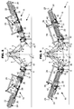
- these second axes (34) are oriented substantially vertically. These second axes (34) are in particular substantially parallel to each other. These second axes (34) allow the work tool (15) to maintain, in plan view of the machine (1), the same orientation relative to the direction of advance (A), in particular to extend substantially perpendicular to the direction of advance (A), regardless of the transverse position of the working tool (15) relative to the support arm (7) in working configuration. This effect is apparent from a comparison of figures 3 and 4 .
- the arm (32) is articulated to the support arm (7) and to the frame (29) of the working tool (15) around these respective second axes (34).
- One of these second axes (34) connects, for example, indirectly the arm (32) to the support arm (7) by means of the articulation piece (35) connected to the support arm (7) by means of the first axis (33) corresponding.
- the other of these second axes (34) connects, for example, indirectly the arm (32) to the frame (29) of the working tool (15), by means of another connecting piece (35) connected to this frame (29) by means of the corresponding first axis (33).
- a second axis (34) may be a physical axis, that is to say an elongate piece of substantially cylindrical section, which allows the assembly of the arm (32) to the support arm (7) or the frame (29) of the work tool (15).
- a second axis (34) may be distinct from the corresponding first axis (33).
- a second axis (34) can also intersect the corresponding first axis (33), in this case the first axis (33) and the second axis (34) together form a hinge cross of the arm (32) to the support arm (7). ) or to the frame (29) of the working tool (15).
- a second axis (34) can also, or alternatively to a physical axis, be a virtual axis. In this case, the second axis (34) is a straight line around which the arm (32) is rotated.
- a second virtual axis (34) exists when, for example, the corresponding articulation of the arm (32) to the support arm (7) or to the frame (29) of the working tool (15) is of the ball-and-socket type.
- one and / or the other of the second axes (34) of articulation respective to the support arm (7) and to the frame (29) of the working tool (15) can (can ) directly connect the arm (32) to the support arm (7), respectively to the frame (29).
- Such an arrangement is obtained for example by means of a hinge cross disposed between the arm (32) and the support arm (7), respectively between the arm (32) and the frame (29), which articulation cross integrates the first and second axes (33 and 34) concerned.
- Another arrangement allowing the arm (32) to be connected directly to the support arm (7), respectively to the frame (29), comprises an articulation ball joint between the arm (32) and the support arm (7), respectively between the arm (32) and the frame (29), which ball incorporates the first and second axes (33 and 34) concerned which are then virtual.
- the connecting device (31) comprises a connecting member (36).
- the connecting member (36) In the working configuration of the support arm (7), the connecting member (36) extends, at least in large part, in front of the support arm (7).
- the connecting member (36) is oriented substantially in the direction of advance (A) when the support arm (7) is in the working configuration.
- oriented substantially in the direction of travel (A) is meant that the connecting member (36) forms with the direction of advance (A) an angle between 0 ° and about 45 °.
- the connecting member (36) is articulated to the support arm (7) around a first connecting axis (37). This first connecting axis (37) connects, for example, directly the connecting member (36) to the support arm (7).
- the first connecting axis (37) is oriented, when the support arm (7) is in working configuration, substantially horizontally and transversely, in particular substantially perpendicular to the direction of advance (A).
- the first link axis (37) is substantially parallel to the first axis (33) of the arm (32).
- the first link axis (37) can be a physical axis.
- the first link axis (37) can also, or alternatively to a physical axis, be a virtual axis.
- the first connecting axis (37) is a straight line around which is rotated the connecting member (36).
- a first virtual link axis (37) exists when, for example, the corresponding articulation of the connecting member (36) to the support arm (7) is of the ball-and-socket type. By pivoting about the first connecting axis (37), the connecting member (36) moves vertically relative to the arm support (7) in working configuration. The arm (32) is remote and not connected to the connecting member (36).
- the connecting member (36) is articulated in particular to the support arm (7) and to the working tool (15) around respective first connecting pins (37).
- One of these first connecting pins (37) connects, for example, directly the connecting member (36) to the support arm (7).
- the other of these first connecting pins (37) connects, for example, directly the connecting member (36) to the frame (29) of the working tool (15).
- These first connecting pins (37) are oriented, when the support arm (7) is in working configuration, substantially horizontally and transversely, in particular substantially perpendicular to the direction of advance (A).
- These first connecting pins (37) are in particular substantially parallel to each other.
- These first connecting pins (37) are in particular substantially parallel to the first axis (33) of the arm (32).
- a first link axis (37) may be a physical axis.
- a first link axis (37) can also, or alternatively to a physical axis, be a virtual axis.
- the first connecting axis (37) is a straight line around which is rotated the connecting member (36).
- a first virtual connecting axis (37) exists when, for example, the corresponding articulation of the connecting member (36) to the support arm (7) or to the frame (29) of the working tool (15) is of the ball-and-socket type. By pivoting about at least one of the first connecting pins (37), the connecting member (36) moves vertically with respect to the support arm (7) in working configuration.
- the connecting member (36) pivots about the first connecting axis (37) which connects to the support arm (7).
- the connecting member (36) also pivots about the first connecting axis (37) which connects it to the frame (29) of the working tool (15).
- the connecting device (31) comprises two arms (32). These are distant from each other and unrelated to each other.
- Each of these arms (32) is articulated on the one hand to the support arm (7) by means of a first axis (33) and a second axis (34), on the other hand to the frame (29) of the working tool (15) also by means of a first axis (33) and a second axis (34).
- Each arm (32) is remote from the connecting member (36) and not connected thereto.
- the means comprise a second connecting axis (38) oriented substantially perpendicularly to the first connecting axis (37). In the working configuration of the support arm (7), this second connecting axis (38) is oriented substantially vertically.
- the connecting member (36) is articulated to the support arm (7) around this second connecting axis (38).
- the second link axis (38) may be a physical axis.
- the second link axis (38) may be distinct from the first link axis (37).
- the second link axis (38) can also cross the first link axis (37), in this case the first link axis (37) and the second link axis (38) together form an articulation cross of the connecting member (36) to the support arm (7).
- the second link axis (38) can also, or alternatively to a physical axis, be a virtual axis.
- a second virtual link axis (38) exists when, for example, the corresponding articulation of the connecting member (36) to the support arm (7) is of the ball-and-socket type.
- the means comprise in particular second connecting pins (38) oriented substantially perpendicularly to the first connecting axis (37). In the working configuration of the support arm (7), these second connecting pins (38) are oriented substantially vertically.
- the connecting member (36) is articulated to the support arm (7) and to the frame (29) of the working tool (15) around these second connecting pins (38) respectively.
- a second link axis (38) may be a physical axis.
- a second link axis (38) may be distinct from the corresponding first link axis (37).
- a second connecting pin (38) can also intersect the corresponding first connecting pin (37), in this case the first connecting pin (37) and the second connecting pin (38) together form a pin joint (37).
- a second link axis (38) may also, or alternatively to a physical axis, be a virtual axis.
- a second virtual connecting axis (38) exists when, for example, the corresponding articulation of the connecting member (36) to the support arm (7) or to the working tool (15) is of the ball-and-socket type.
- an arm (32) extends forwardly from the support arm (7) in working configuration, in the direction of the lower part of the frame (29).
- the first axis (33), connecting this arm (32) to the frame (29) of the working tool (15) is located under the device of displacement (21). A large part of the weight of the working tool (15) is thus taken up by the arm (32).
- the first axis (33), connecting the arm (32) to the frame (29) of the working tool (15), is in particular disposed substantially in line with a line parallel to the axis of rotation (23). of the collection device (20) and passing through the center of gravity of the working tool (15).
- this arm (32) carries the working tool (15) in a balanced manner, the tendency of the working tool (15) to pivot about the first axis (33), connecting the arm (32). to the frame (29) is reduced.
- the two arms (32) extend forwardly from the support arm (7) in working configuration, towards the lower part of the frame (29).
- the first axes (33) connecting these arms (32) to the frame (29) of the working tool (15) are located under the displacement device (21).
- These first axes (33) connecting the arms (32) to the frame (29) of the working tool (15) are in particular arranged substantially perpendicular to a line parallel to the axis of rotation (23) of the device pickup (20) and passing through the center of gravity of the work tool (15). In this way, the working tool (15) is almost in equilibrium on the arms (32) which carry it, and the forces in the connecting member (36) - stresses in tension or in compression - are very small.
- the means comprise a first actuator (39) which moves the working tool (15) relative to the support arm (7) transversely to the direction of advance (A).
- This first actuator (39) is, for example, a hydraulic cylinder.
- the first actuator (39) connects two elements among the support arm (7), the connecting device (31) and the frame (29) of the working tool (15). By being connected for example to the connecting device (31), the first actuator (39) is connected to one of the arms (32) or to the connecting member (36).
- the first actuator (39) is disposed, in particular articulated, between the support arm (7) and one of the arms (32). It extends non-parallel to this arm (32).
- the first actuator (39) when the first actuator (39) is driven at shortening or elongation, it rotates the arm (32) about the second axis (34) which connects to the support arm (7).
- the first actuator (39) could also be articulated between the support arm (7) and the frame (29) of the working tool (15), extending non-parallel to the arms (32).
- the first actuator (39) moves the work tool (15) between a first transverse position relative to to the support arm (7) and a second position transverse to the support arm (7).
- the inner lateral end (16) of the working tool (15) In the first transversal position illustrated in figure 3 , the inner lateral end (16) of the working tool (15) is brought closer to a first vertical plane (P1) median of the frame (2). This first plane (P1) is oriented in the direction of advance (A).
- the inner lateral end (16) of the working tool (15) is situated between the first plane (P1) and the wheel (6) located, relative to the central beam (3), on the same side as the work tool (15).
- the working tool (15) can occupy a first working position obtained by positioning the support arm (7) in the working configuration, and positioning the working tool (15) in the first transverse position by relative to the support arm (7).
- the inner lateral end (16) of the working tool (15) is substantially in the first vertical plane (P1) median of the frame (2).
- this inner lateral end (16) is then under the central beam (3) of the frame (2).
- the inner end (16) of the working tool (15) is moved away from the first vertical plane (P1) of the frame (2).
- the working tool (15) can occupy a second working position obtained by positioning the support arm (7) in the working configuration and by positioning the working tool (15) in the second transversal position relative to at the support arm (7).
- the inner lateral end (16) of the working tool (15) is located substantially at the inner side (40) of the tire of the wheel (6) located, relative to the central beam (3), on the same side as the working tool (15), or slightly recessed from the inner side (40).
- the distance separating the inner lateral end (16) of the first plane (P1) is equal to, or slightly less than, half the distance separating the respective internal flanks (40) of the tires of the wheels (6).
- the support arm (7) being in the working configuration, two vertical planes each passing through a length of a respective arm (32), are substantially parallel to each other.
- the two arms (32) have substantially the same length. In this way, the moving the working tool (15) between the first transverse position and the second transverse position is substantially parallel to a length of the support arm (7).
- the working tool (15) comprises a second median vertical plane (P2) situated midway between the inner and outer lateral ends (16 and 17), an arm (32) is located between the inner lateral end (16) and the second median vertical plane (P2), and the other arm (32) is located between the second median vertical plane (P2) and the outer lateral end (17).
- P2 median vertical plane
- the frame (29) of the working tool (15) is firmly held relative to the support arm (7) in working configuration.
- an arm (32) is placed substantially at the inner end (13) of the support arm (7). This is the arm (32) located between the inner lateral end (16) of the working tool (15) and the second vertical plane (P2) median.
- An arm (32) is placed substantially at the outer end (14) of the support arm (7). This is the arm (32) located between the second plane (P2) vertical median and the outer lateral end (17).
- the connecting member (36) comprises a bar (41).
- the connecting member (36) is constituted by a bar (41).
- this bar (41) is oriented essentially in the direction of advance (A).
- oriented substantially in the direction of travel (A) is meant that this bar (41) forms with the direction of advance (A), an angle between 0 ° and about 45 °.
- the bar (41) is articulated to the support arm (7) and to the frame (29) of the working tool (15) by means of the first and second connecting pins (37 and 38).
- the bar (41) is articulated directly to the support arm (7) by means of at least one of the first and second connecting pins (37 and 38) concerned, and directly to the frame (29) of the work tool (15) by means of at least one of the other first and second links (37 and 38) concerned.
- the bar (41) is of fixed or variable length.
- a bar (41) of variable length comprises, for example, elements screwed with left and right steps. It can also consist of elements that can slide into each other and be immobilized relative to each other by means of a pin capable of engaging in several adjustment holes.
- such a bar (41) of variable length can take the form of a jack, including a hydraulic cylinder.
- the connecting member (36) and at least one of the arms (32) are in respective planes which are vertically distant from each other when the support arm (7) is in the working configuration.
- the connecting member (36) extends in a plane which, when the support arm (7) is in the working configuration, is vertically further from the ground than that in which an arm (32) extends, in particular each arm (32).
- an arm (32), in particular each arm (32) extends over at least part of its length, under the displacement device (21).
- the connecting member (36) extends for its part, at least over part of its length, from the support arm (7) towards the upper vertical end (19) of the working tool (15). ), for example, towards an upper part of the deflector (26) placed at the rear of the displacement device (21).
- the machine (1) comprises at least one second actuator (42). It connects two elements among the support arm (7), the connecting device (31) and the frame (29) of the working tool (15).
- the second actuator (42) is articulated between the support arm (7) and an arm (32).
- the second actuator (42) is, for example, a cylinder, in particular a hydraulic cylinder.
- the second actuator (42) makes it possible to move the working tool (15) with respect to the support arm (7) towards at least one raised position of the working tool (15) with respect to the support arm ( 7), wherein the working tool (15) is remote from the ground. This raised position is illustrated in figure 7 .
- two second actuators (42) are provided for the working tool (15).
- Each is articulated to the support arm (7) and a respective arm (32).
- the movement towards the raised position is effected by the two second actuators (42) which are, for example, actuated simultaneously.
- the working tool (15) does not act on the plants on the ground.
- This raised position is located between the working position and the transport position of the working tool (15).
- Moving the working tool (15) relative to the support arm (7), by means of the second actuator (42), towards the raised position of the working tool (15) relative to the support arm (7) comprises a vertical component. This movement can be made while the support arm (7) is in the working configuration.
- This displacement is essentially vertical.
- the working tool (15) remains substantially parallel to the ground during this movement.
- the working tool (15) extends substantially perpendicularly to the direction of advancement (A).
- the inner and outer lateral ends (16 and 17) of the working tool (15) ) are located substantially at the same height above the ground.
- the support arm (7) in the working configuration remains stationary, or substantially immobile, relative to the frame (2).
- the raised position obtained, while the support arm (7) is in the working configuration is, for example, a swathing passage position of the working tool (15), allowing in particular the passage over a low windrow previously formed by a harvesting machine set in wide spreading mode.
- the vertical clearance of the working tool (15) above the ground is important, between 200 mm and 400 mm for example, close to 300 mm for example.
- a raised position is a first raised position.
- This first raised position that can occupy the working tool (15) relative to the support arm (7) is obtained by the transverse positioning of the working tool (15) in the first transverse position relative to the support arm (7).
- the raised position illustrated in figure 7 is in this case such a first raised position. From the first working position of the working tool (15), the actuation of the second actuator (s) (42) has the effect of raising the work tool (15) so that the latter is moved towards the first raised position relative to the support arm (7).
- another raised position is a second raised position.
- This raised second position that can be occupied by the working tool (15) relative to the support arm (7) is obtained by the transverse positioning of the working tool (15) in the second transverse position relative to the support arm ( 7). From the second working position of the working tool (15), actuation of the second actuator (s) (42) has the effect of raising the working tool (15) so that the latter is moved towards the second raised position relative to the support arm (7).
- the working tool (15) can in particular occupy the first and second raised positions relative to the support arm (7), namely, sometimes one, sometimes the other, as required, when the support arm (7) is in the working configuration. It is also possible to move the working tool (15) from the first raised position to the second raised position, and vice versa, by actuation of the first actuator (39), while the support arm (7) is in the configuration. working. Thus, since the first raised position illustrated at figure 7 , the working tool (15) can be moved away from the central beam (3) of the frame (2) to reach its second raised position, the support arm (7) remaining, during this movement, in its working configuration .
- the third actuator (11) arranged between the support arm (7) and the frame (2) makes it possible to move the support arm (7) relative to the frame (2) towards the intermediate configuration with respect to the chassis ( 2), which is located between the working configuration and the transport configuration.
- the outer end (14) of the support arm (7) is at a height above the ground greater than its inner end (13).
- the outer end (14) is placed behind the inner end (13).
- the support arm (7) therefore has an oblique orientation, intermediate between its substantially horizontal and transverse orientation in the working configuration, and its substantially horizontal orientation and substantially parallel to the direction of advance (A) in the transport configuration.
- the working tool (15) extends obliquely with respect to a vertical plane perpendicular to the direction of advance (A).
- the working tool (15) can occupy the position or positions raised relative to the support arm (7) when the latter is in the intermediate configuration. In this case, the working tool (15) is distant from the ground. It does not act on the plants present on the ground.
- the figure 8 shows that the working tool (15) can occupy the second raised position, relative to the support arm (7), when the latter is in the intermediate configuration.
- the figure 9 shows that the working tool (15) can occupy the first raised position, relative to the support arm (7), when the latter is in the intermediate configuration.
- the first actuator (39) can be actuated so as to move the working tool (15) relative to the support arm (7) of the second transverse position - see it figure 8 - to the first transversal position - see the figure 9 .
- the inner lateral end (16) of the working tool (15) is brought closer to the central beam (3) of the frame (2).
- the arm (32), in particular each arm (32), connecting the frame (29) of the working tool (15) to the support arm ( 7) is pointing upwards and forwards. In this way, the working tool (15) has an advanced positioning relative to the support arm (7). The total length of the machine (1) to transport is reduced.
- the working tool (15) When the working tool (15) is in a raised position, in particular in each of the first and second raised positions, relative to the support arm (7) in the intermediate configuration, the outer lateral end (17) of the The work tool (15) is at a greater height above the ground than its inner end (16). In addition, the outer lateral end (17) of the work tool (15) is located further back than the inner end (16). Thus, in a raised position, particularly in each of the first and second raised positions, relative to the support arm (7) in the intermediate configuration, the working tool (15) extends obliquely with respect to a vertical plane. perpendicular to the direction of advancement (A).
- the inner lateral end (16) of the working tool (15) is located at a higher height above the ground in the intermediate configuration of the support arm (7) than in the working configuration of the support arm (7) relative to the frame (2), especially when the working tool (15) occupies the first transverse position relative to the support arm (7).
- the intermediate configuration of the support arm (7) is, for example, a swath passage configuration.
- a raised position of the working tool (15) relative to the support arm (7) in the intermediate configuration is, for example, a swath passage position of the working tool (15), in particular allowing the passage above a tight swath and high height. In this raised position, the vertical clearance of the work tool (15) above the ground is quite considerable.
- the inner lateral end (16) rises to a height of between 500 mm and 1000 mm, for example, while the outer lateral end (17) is at a distance of between 800 mm and 1300 mm from the ground. for example.
- the second actuator (42) comprises a lightening means of the ground work tool.
- the second actuator (42) comprises, for example, a jack which provides the functions of both lifting and lightening of the working tool (15) relative to the support arm (7).
- this jack is, for example, connected to a pressure accumulator.
- the support arm (7) in working configuration remains stationary, or substantially immobile, relative to the frame (2). It is the second actuator (42) placed in "floating" mode which allows the vertical movement of the working tool (15) relative to the frame (2), these movements being to a certain extent controlled and damped.
- Each second actuator (42) articulated to the support arm (7) and a respective arm (32) comprises such a lightening means.
- each arm (32) to the frame (29) of the work tool (15) and the arm support (7) are configured to allow pivoting of the working tool (15) relative to the support arm (7) in the working configuration around a virtual axis oriented substantially in the direction of travel (A). ). Thanks to this lightening means and to these joints associated with each arm (32), the arms (32) can, during work, move vertically relative to the support arm (7) independently of one another. Thus, when the working tool (15) is moving on an uneven ground, its inner and outer lateral ends (16 and 17) can move vertically in different directions and / or with different amplitudes.
- each arm (32) substantially takes up the same fraction of the vertical forces exerted on these arm (32) by the working tool.
- the lightening of the working tool (15) is balanced between the two arms (32).
- the lightening of the working tool (15) over its working width is uniform.
- the embodiment of the figures comprises two working tools (15) each articulated to the frame (2) by means of a respective support arm (7) located on a respective side of the frame (2).
- the figures 1 and 2 are a single working tool (15), arranged on the right side of the machine (1), the second working tool (15) is placed on the left side of the machine (1).
- Each working tool (15) comprises a frame (29) connected to the corresponding support arm (7) via a respective connecting device (31).
- the first actuator (39) associated with a working tool (15) can be actuated when the support arm (7) is in the working configuration or in the intermediate configuration.
- the respective collection (20) and displacement (21) devices are then more or less distant from each other, which makes it possible to vary the width of a central windrow obtained from plants collected by each device. pickup (20) and moved by each moving device (21) rotating in the direction of the central beam (3) of the frame (2).
- each support arm (7) When each support arm (7) is in its respective working configuration and at least one of the working tools (15) is in the second transversal position relative to the corresponding support arm (7), so that this working tool (15) is in its second working position, the inner lateral ends (16) of these work tools (15) are clearly spaced l one of the other perpendicular to the direction of advance (A).
- each working tool (15) can be in the second transverse position relative to the support arm (7) in working configuration, that is to say that each working tool (15) is then in its second working position.
- the distance separating the respective inner lateral ends (16) allows the formation of a central windrow deposited between the two working tools (15), from, for example, lateral swaths taken up by each working tool (15). ) respectively.
- each support arm (7) When each support arm (7) is in its respective working configuration and each working tool (15) is in the first transverse position relative to the corresponding support arm (7), that is to say when each work tool is in its respective first working position, the inner side ends (16) of these work tools (15) are juxtaposed.
- This arrangement of working tools (15) allows the formation of a windrow deposited on the left or right side of the machine (1), from, for example, a continuous width of plants collected, for example, from mown plants. or faded spread on the ground.
- a transposition of the machine from a work situation to a transport situation comprises for example the steps detailed below.
- the working tool (15) carried by the support arm (7) in working configuration is first raised from the ground by actuation of the second actuators (42). This vertical movement is operated while maintaining the transverse position of the working tool (15) relative to the support arm (7). Then, the support arm (7) is moved from its working configuration to its intermediate configuration. If the working tool (15) is, relative to the support arm (7), in a transverse position other than the first transverse position, it is then moved by actuation of the first actuator (39), in order to reach this first transversal position. Finally, the support arm (7) is folded upwards and backwards until it reaches its transport configuration.
- An agricultural machine (1) for harvesting plants according to the invention may be a mower.
- a working tool is configured to perform mowing work.
- a working tool comprises, for example, a mowing device comprising a bar along which extend disks or drums equipped with knives.
- This mowing device may be followed by a device for conditioning fingers, flails or rollers, and / or a windrowing device comprising one or more baffles, or a belt or rollers, for moving the mowed plants transversely. to the advancement direction.
- Such a machine comprises, for example, two such working tools each placed on a respective side of the frame.
- An agricultural machine (1) for harvesting plants according to the invention may be a machine carried, in particular a machine carried at the rear of a tractor.
- the frame On such a machine, the frame has a central portion having a coupling device adapted to attach to the three-point hitch of a tractor.
Landscapes
- Life Sciences & Earth Sciences (AREA)
- Environmental Sciences (AREA)
- Engineering & Computer Science (AREA)
- Mechanical Engineering (AREA)
- Soil Sciences (AREA)
- Zoology (AREA)
- Agricultural Machines (AREA)
- Harvester Elements (AREA)
Description
- La présente invention se rapporte à une machine agricole pour la récolte de végétaux, notamment de fourrage, cette machine étant déplaçable dans une direction d'avancement et comportant notamment :
- un châssis,
- au moins un bras support articulé au châssis et déplaçable par rapport au châssis entre une configuration de travail dans laquelle le bras support s'étend latéralement par rapport au châssis, et une configuration de transport dans laquelle le bras support est replié de sorte que son encombrement perpendiculairement à la direction d'avancement (A) est réduit,
- au moins un outil de travail comportant une extrémité latérale intérieure et une extrémité latérale extérieure, et pouvant occuper au moins une position de travail dans laquelle l'outil de travail agit sur des végétaux présents au sol, et au moins une autre position,
- un dispositif de liaison par l'intermédiaire duquel un bâti de l'outil de travail est relié au bras support, ce dispositif de liaison autorisant, au moins lorsque le bras support est dans la configuration de travail, un premier déplacement de l'outil de travail par rapport au bras support au cours duquel l'extrémité latérale intérieure et l'extrémité latérale extérieure de l'outil de travail se déplacent verticalement par rapport au bras support et dans la même direction verticale par rapport à celui-ci.
- Une machine de ce type est connue du document
US 8 186 138 B2 . Cette machine est du type connu sous l'appellation de « Merger ». Cette machine comporte un châssis conçu pour être attelé à l'arrière d'un tracteur, et supporté au sol par des roues dans sa partie arrière. Sur au moins un côté latéral du châssis est articulé un bras support portant un outil de travail. Ce bras support peut être placé dans une configuration de travail dans laquelle l'outil de travail s'étend perpendiculairement à la direction d'avancement et sensiblement horizontalement. L'outil de travail comporte un rotor à dents qui, pendant le travail, s'étend perpendiculairement à la direction d'avancement et ramasse les végétaux présents au sol. Les végétaux ramassés sont déplacés vers l'arrière par le rotor, en direction d'un convoyeur à tapis qui déplace les végétaux perpendiculairement à la direction d'avancement, en direction d'un côté latéral de l'outil de travail. Sur la machine connue, l'outil de travail est, dans sa partie arrière, relié à un support au moyen d'un axe orienté horizontalement et parallèlement à la direction d'avancement lorsque le bras support est en configuration de travail. Ce support est à son tour relié au bras support au moyen d'une première bielle et d'une deuxième bielle située sous la première bielle. A chacune de ses extrémités, la première bielle est articulée au bras support et au support au moyen d'axes physiques respectifs qui sont orientés horizontalement et transversalement à la direction d'avancement lorsque le bras support se trouve en configuration de travail. Il résulte de cet agencement que les première et deuxième bielles peuvent se déplacer verticalement par rapport au bras support en configuration de travail, de sorte que l'outil de travail peut, dans son intégralité, se déplacer vers le haut ou bien vers le bas pour suivre un terrain au profil inégal. Cependant, ce déplacement est uniquement vertical. Le bras support étant en configuration de travail, la distance, mesurée horizontalement et perpendiculairement à la direction d'avancement, qui sépare l'outil de travail du châssis, demeure constante. Au cours de la période de récolte, les végétaux peuvent, consécutivement à leur fauchage, être regroupés en andains dont la largeur et l'espacement les uns des autres varient suivant les machines de fauchage et/ou d'andainage utilisées. Un cas d'utilisation de la machine connue consiste en ce que le tracteur et la machine chevauchent un premier andain, de sorte que ce premier andain passe entre les roues du tracteur et entre les roues de la machine, et en ce que l'outil de travail ramasse un deuxième andain parallèle au premier andain et placé sur un côté latéral du tracteur. Ce deuxième andain est déposé par la machine sur ou le long du premier andain, ou bien sur ou le long d'un troisième andain parallèle au deuxième andain et placé à plus grande distance du premier andain. En pareil cas d'utilisation, la trajectoire du tracteur et de la machine est imposée par le fait que leurs roues respectives ne doivent pas écraser le premier andain. Il se peut donc qu'en fonction de la largeur du deuxième andain, et de la distance qui le sépare du premier andain, ce deuxième andain ne soit repris que partiellement par l'outil de travail. Ce dernier laisse donc une fraction non ramassée du deuxième andain. Un ramassage complet du deuxième andain requiert donc un passage supplémentaire de la machine, ce qui augmente le temps passé au champ et les coûts d'exploitation, et réduit la productivité. En sus, le fait pour l'outil de travail de scinder le deuxième andain en deux parties, augmente le risque de bourrage de végétaux au sein de l'outil de travail. Par ailleurs, la manière dont le deuxième andain est redéposé sur ou le long du premier ou du troisième andain n'est pas modifiable, car elle est imposée par la distance séparant l'outil de travail du châssis dont les roues chevauchent le premier andain. Par conséquent, l'allure du nouvel andain, obtenu par le regroupement du deuxième andain et du premier ou du troisième andain, n'est pas toujours optimale suivant la nature des végétaux et les conditions météorologiques rencontrées. Enfin, la machine connue ne permet pas de modifier le positionnement transversal de l'outil de travail par rapport au tracteur. Par conséquent, il n'est notamment pas possible d'ajuster la largeur totale de l'ensemble tracteur - machine au travail. - Une autre machine connue du document
WO 2011/112077 est conforme au préambule de la revendication 1. Sur cette machine, l'outil de travail est relié au bras support concerné au moyen d'un dispositif de liaison comprenant un premier bras et un deuxième bras. Le premier bras s'étend sensiblement dans la direction d'avancement, depuis un premier axe vertical d'articulation au bras support. A son extrémité distante du premier axe, le premier bras porte un deuxième bras au moyen d'un deuxième axe d'articulation s'étendant sensiblement dans la direction d'avancement. Ce deuxième bras s'étend transversalement à la direction d'avancement et porte, à son extrémité distante du deuxième axe, le bâti de l'outil de travail concerné. Par pivotement du deuxième bras autour du deuxième axe, l'outil de travail peut se déplacer verticalement. Par ailleurs, le deuxième bras est télescopique de manière à autoriser un déplacement transversal de l'outil de travail. Ce dispositif de liaison est complexe et encombrant du fait des premier et deuxième bras qui s'étendent dans des directions respectives différentes. En particulier, l'agencement télescopique du deuxième bras est compliqué et onéreux. Enfin, pendant le travail, le deuxième axe d'articulation est soumis à des sollicitations mécaniques considérables. Celles-ci proviennent d'une part du mouvement vertical du deuxième bras par rapport au premier. D'autre part, les efforts que les végétaux déplacés par la machine avançant dans le champ exercent sur l'outil de travail, génèrent un couple de torsion autour d'un axe vertical passant par le deuxième axe d'articulation. Ce couple est élevé en raison de la longueur importante du deuxième bras dirigé transversalement, ce qui peut entraîner une usure rapide du deuxième axe. - La présente invention a pour but de proposer une machine agricole pour la récolte de végétaux qui ne présente pas les inconvénients précités.
- A cet effet, l'invention est caractérisée en ce que le dispositif de liaison comporte au moins un bras orienté essentiellement dans la direction d'avancement lorsque le bras support est en configuration de travail, que ce bras est articulé au bras support autour d'un premier axe qui est orienté transversalement à la direction d'avancement et sensiblement horizontalement lorsque le bras support est en configuration de travail, et que ce bras peut, par pivotement autour de ce premier axe, se déplacer verticalement par rapport au bras support en configuration de travail, de sorte que l'outil de travail puisse se déplacer verticalement par rapport audit bras support.
- Grâce aux moyens dont le dispositif de liaison est pourvu, la distance, mesurée horizontalement et perpendiculairement à la direction d'avancement, qui sépare l'outil de travail du châssis, peut être ajustée aux différentes conditions de travail. Ainsi, le positionnement transversal de l'outil de travail par rapport au tracteur peut être modifié. De plus, il est possible d'ajuster la largeur totale de l'ensemble tracteur - machine au travail. Par le déplacement transversal de l'outil de travail par rapport au bras support qu'ils autorisent, les moyens permettent d'ajuster facilement la distance par rapport au châssis à laquelle les végétaux récoltés par l'outil de travail sont redéposés au sol par la machine, notamment sous la forme d'un andain. L'outil de travail de la machine, selon l'invention, peut notamment être destiné à andainer des végétaux au sol. Dans ce cas, lorsque le tracteur chevauche un premier andain qui passe entre ses roues, les moyens permettent de placer transversalement l'outil de travail à la distance adéquate du châssis pour reprendre, en totalité et en une fois, un deuxième andain placé sur un côté latéral du tracteur. En sus, ce deuxième andain peut être redéposé par la machine de manière optimale sur ou le long du premier andain, ou bien sur ou le long d'un troisième andain placé à plus grande distance du tracteur, afin d'obtenir un nouvel andain de plus gros volume. Les moyens permettent donc d'ajuster la largeur, la hauteur et la forme générale de ce nouvel andain en fonction de la nature des végétaux, des conditions météorologiques et de la capacité de traitement de la presse ou de l'ensileuse utilisée par la suite pour ramasser ce nouvel andain. Plus généralement, les moyens permettent un réglage aisé du recouvrement transversal entre les largeurs de travail, d'une part de l'outil de travail d'une machine selon l'invention attelée à l'arrière d'un tracteur, d'autre part d'une unité de travail placée à l'avant du tracteur. Cet avantage s'adresse bien entendu à un outil de travail et à une unité de travail du type précité, mais également à un outil de travail et à une unité de travail destinés à faucher des végétaux. Par ailleurs, comme les moyens permettent au deuxième déplacement d'être opéré indépendamment du premier déplacement vertical de l'outil de travail par rapport au bras support, le dispositif de liaison selon l'invention permet à l'outil de travail de bien suivre le terrain, quelle que soit la position transversale de l'outil de travail par rapport au châssis. Le suivi du terrain est avantageusement obtenu par le premier déplacement vertical de l'outil de travail par rapport au bras support. Au cours de ce premier déplacement, le bras support peut demeurer immobile ou au moins sensiblement immobile, si bien que les masses suspendues, en mouvement au cours du premier déplacement, sont avantageusement limitées aux masses respectives de l'outil de travail et du dispositif de liaison. Enfin, le dispositif de liaison regroupant les fonctions de déplacement vertical et de déplacement transversal de l'outil de travail par rapport au bras support, les moyens techniques pour articuler le bras support au châssis et pour assurer les déplacements du bras support par rapport au châssis, peuvent être simplifiés et allégés. Notamment, le bras support peut demeurer immobile, ou sensiblement immobile, par rapport au châssis lorsque ce bras support est dans la configuration de travail. En sus, le bras support peut être simplifié et allégé, en étant formé par une pièce d'un seul tenant qui n'intègre pas de liaisons articulées et/ou télescopiques.
- Du fait que le dispositif de liaison du bâti de l'outil de travail au bras support, comporte un bras orienté essentiellement dans la direction d'avancement lorsque le bras support est en configuration de travail, le dispositif de liaison selon l'invention peut demeurer compact et léger. Cette compacité va de pair avec un bon suivi du terrain puisqu'au travail, le bras peut se déplacer verticalement par rapport au bras support, autour du premier axe transversal et sensiblement horizontal par lequel le bras est articulé au bras support. L'orientation longitudinale du bras et l'orientation transversale du premier axe permettent à ces éléments de bien résister aux efforts longitudinaux exercés sur l'outil de travail par les végétaux déplacés. Ainsi, le dispositif de liaison selon l'invention, reliant le bâti de l'outil de travail au bras support, présente une durabilité améliorée.
- Selon une caractéristique avantageuse de l'invention, les moyens comportent un premier actionneur qui permet de déplacer l'outil de travail par rapport au bras support, transversalement à la direction d'avancement, entre une première position transversale par rapport au bras support, dans laquelle l'extrémité latérale intérieure de l'outil de travail est rapprochée d'un premier plan vertical médian du châssis, et une deuxième position transversale par rapport au bras support, dans laquelle cette extrémité latérale intérieure est éloignée de ce premier plan vertical médian. Dans la première position transversale de l'outil de travail, la largeur de la machine est réduite. Lorsque la machine est du type attelée à l'arrière d'un tracteur, l'extrémité latérale intérieure de l'outil de travail placé dans cette première position transversale, se situe dans le prolongement de l'essieu arrière du tracteur. L'outil de travail peut alors agir sur des végétaux présents au sol et situés à l'arrière du tracteur. Dans le cas d'un outil de travail destiné à la mise en andains de végétaux, l'outil de travail peut alors reprendre un andain passant entre les roues du tracteur pour, par exemple, le déplacer en direction de l'extrémité latérale extérieure de l'outil de travail. Dans la deuxième position transversale de l'outil de travail, l'extrémité latérale intérieure est par exemple située sensiblement dans le prolongement de la roue arrière du tracteur située du même côté que celui où l'outil de travail s'étend par rapport au châssis de la machine. Cet outil de travail peut ainsi agir sur des végétaux situés de ce côté du tracteur, qu'il s'agisse d'un outil de travail destiné à andainer ou à faucher ces végétaux. Notamment dans le cas d'un outil de travail destiné à andainer des végétaux, celui-ci peut ramasser un andain latéral placé de ce côté-ci du tracteur, afin de le redéposer sous la forme d'un andain, par exemple plus ou moins au centre de la machine. Un outil de travail destiné à faucher peut, dans cette deuxième position transversale, faucher des végétaux présents dudit côté du tracteur et les regrouper en un andain latéral ou plus ou moins central par rapport à la machine. Dans la deuxième position transversale, l'outil de travail peut présenter un certain recouvrement avec une unité de travail placée à l'avant du tracteur.
- Selon une caractéristique avantageuse de l'invention, la machine comporte deux outils de travail articulés chacun au châssis au moyen d'un bras support respectif situé d'un côté respectif du châssis. Les moyens pour déplacer chaque outil de travail autorisent ainsi un réglage de la largeur totale de travail de la machine. En sus, les moyens permettent d'espacer plus ou moins ces outils de travail l'un de l'autre en vue d'ajuster la largeur d'un andain formé au centre de la machine par l'un au moins de ces outils de travail. De plus, les moyens autorisent un réglage du recouvrement entre les largeurs de travail respectives des outils de travail d'une machine selon l'invention attelée à l'arrière d'un tracteur, et la largeur de travail d'une unité de travail placée à l'avant du tracteur.
- Selon une autre caractéristique avantageuse de l'invention, lorsque chaque bras support se trouve dans sa configuration de travail respective et que l'un au moins des outils de travail se trouve dans la deuxième position transversale par rapport au bras support correspondant, les extrémités latérales intérieures de ces outils de travail sont nettement écartées l'une de l'autre perpendiculairement à la direction d'avancement (A), et que, lorsque chaque bras support se trouve dans sa configuration de travail respective et que chaque outil de travail se trouve dans la première position transversale par rapport au bras support correspondant, les extrémités latérales intérieures de ces outils de travail sont juxtaposées. La première position transversale permet à la machine d'agir sur une largeur continue de végétaux. Des outils de travail destinés à andainer peuvent ainsi ramasser une largeur continue de végétaux, par exemple de végétaux fauchés ou fanés étalés au sol, et les déposer en un andain du côté gauche ou droit de la machine. La deuxième position transversale autorise chaque outil de travail à agir sur des végétaux répartis sur la gauche et sur la droite de la machine. Des outils de travail destinés à andainer peuvent ainsi former un andain central déposé entre les deux outils de travail, à partir de végétaux ramassés par chaque outil de travail respectif, par exemple à partir de deux andains latéraux qui sont chacun repris par un outil de travail respectif.
- D'autres caractéristiques et avantages de l'invention ressortiront de la description ci-après avec référence aux figures annexées qui représentent une forme non limitative de réalisation de la machine selon l'invention.Sur ces figures
- la
figure 1 représente une vue partielle, en perspective, d'une forme de réalisation d'une machine selon l'invention, comportant quelques coupes partielles ; - la
figure 2 est un agrandissement de la vue de lafigure 1 ; - la
figure 3 représente une vue de dessus de la forme de réalisation de lafigure 1 , comportant quelques coupes partielles ; - la
figure 4 représente une vue de dessus de la forme de réalisation de lafigure 1 , comportant quelques coupes partielles ; - la
figure 5 représente une vue de côté de la forme de réalisation de lafigure 1 , attelée à un tracteur, comportant quelques coupes partielles ; - la
figure 6 représente une autre vue de côté de la forme de réalisation de lafigure 1 ; - les
figures 7 à 9 représentent chacune une vue de face de la forme de réalisation de lafigure 1 , comportant quelques coupes partielles. - La machine (1) selon l'invention est une machine agricole pour la récolte de végétaux, en particulier de fourrage. Cette machine (1) comporte un châssis (2). Ainsi qu'il apparaît à la
figure 1 , celui-ci comprend une poutre centrale (3) qui possède à son extrémité avant un dispositif d'attelage (4) pour l'accrocher à un tracteur (T) permettant de déplacer la machine dans une direction d'avancement (A). Dans la suite de la description, les notions « avant », « arrière », « en aval », « gauche » et « droite » sont définies par rapport à la direction d'avancement (A), tandis que les notions « haut », « dessus », « inférieur », « supérieur » et « sous » se rapportent au sol. La poutre centrale (3) s'étend suivant la direction d'avancement (A). Dans sa partie arrière, la poutre centrale (3) porte des montants latéraux (5) qui s'étendent en direction du sol. Le châssis (2) est supporté au sol par des roues (6). Chaque roue (6) est portée par un montant latéral (5) respectif. Au châssis (2) est articulé au moins un bras support (7) qui est porté par un montant latéral (5). Le bras support (7) est relié à ce montant latéral (5) via un élément d'articulation (8). Cet élément d'articulation (8) est articulé au montant latéral (5) au moyen d'un premier axe d'articulation (9). Cet élément d'articulation (8) est disposé en avant des roues (6). Ce premier axe d'articulation (9) s'étend sensiblement dans la direction d'avancement (A). Ce premier axe d'articulation (9) est de plus sensiblement horizontal. Le bras support (7) est articulé à l'élément d'articulation (8) au moyen d'un deuxième axe d'articulation (10) sensiblement vertical lorsque la machine travaille. Ce deuxième axe d'articulation (10) est sensiblement perpendiculaire au premier axe d'articulation (9). Un troisième actionneur (11) est disposé entre le bras support (7) et le châssis (2). Ce troisième actionneur (11), par exemple un vérin, est articulé au châssis (2) et à l'élément d'articulation (8) et permet de pivoter ce dernier autour du premier axe d'articulation (9). Une bielle (12) est par ailleurs articulée au châssis (2) et au bras support (7). Lorsque le troisième actionneur (11) est en position raccourcie, le deuxième axe d'articulation (10) est sensiblement vertical. Le bras support (7) s'étend alors dans une configuration de travail dans laquelle il s'étend latéralement par rapport au châssis (2). Cette configuration de travail du bras support (7) est notamment illustrée auxfigures 1 ,3 et5 . Le bras support (7) s'étend de plus en avant de la roue (6) portée par le montant latéral (5) auquel le bras support (7) est relié. Notamment, le bras support (7) est sensiblement perpendiculaire à la direction d'avancement (A). Il est de plus sensiblement horizontal. Lorsque le troisième actionneur (11) est actionné à l'allongement, il fait pivoter vers le haut l'élément d'articulation (8) autour du premier axe d'articulation (9). Simultanément, le bras support (7) pivote autour du deuxième axe d'articulation (10), en raison de la bielle (12) qui le relie au châssis (2). Le bras support (7) pivote alors, depuis sa configuration de travail, vers le haut et vers l'arrière par rapport au châssis (2). Lorsque le troisième actionneur (11) est complètement allongé, le bras support (7) est placé dans une configuration de transport. Cette configuration de transport du bras support (7) est illustrée à lafigure 6 . Dans cette configuration, le bras support (7) replié occupe un encombrement réduit suivant une direction perpendiculaire à la direction d'avancement (A). Cet encombrement réduit est notamment obtenu par le fait que le bras support (7) s'étend alors au-dessus de la roue (6) portée par le montant latéral (5) correspondant. De plus, le bras support (7) s'étend sensiblement dans la direction d'avancement (A). Il s'étend sensiblement à l'horizontale. Dans la configuration de transport, l'extrémité intérieure (13) du bras support (7) reliée à l'élément d'articulation (8), se situe en avant de la roue (6). L'extrémité extérieure (14) du bras support (7) distante de son extrémité intérieure (13), est placée en arrière de la roue (6). Cette cinématique de repliement du bras support (7) permet, pour le transport, à la fois une largeur réduite de la machine (1) et une bonne maniabilité grâce à un empattement réduit. - Le bras support (7) porte un outil de travail (15). Ce dernier comporte une extrémité latérale intérieure (16) et une extrémité latérale extérieure (17). Dans la configuration de travail du bras support (7), l'outil de travail (15) est latéralement, c'est-à-dire transversalement à la direction d'avancement (A), délimité par lesdites extrémités latérales (16 et 17). L'outil de travail (15) comporte également une extrémité verticale inférieure (18) et une extrémité verticale supérieure (19). Dans la configuration de travail du bras support (7), l'outil de travail (15) est verticalement délimité par lesdites extrémités verticales (18 et 19). Dans la configuration de travail du bras support (7), l'outil de travail (15) peut occuper au moins une position de travail dans laquelle l'outil de travail agit sur des végétaux présents au sol. Dans une telle position de travail illustrée à la
figure 5 , l'outil de travail (15) s'étend latéralement par rapport à la poutre centrale (3) du châssis (2). L'extrémité latérale intérieure (16) est plus proche de la poutre centrale (3) que ne l'est l'extrémité latérale extérieure (17). L'extrémité verticale inférieure (18) est proche ou située sensiblement au niveau du sol. Dans cette position de travail, l'outil de travail (15) s'étend transversalement à la direction d'avancement (A), notamment sensiblement perpendiculairement à celle-ci. L'outil de travail (15) s'étend de plus essentiellement dans un plan sensiblement horizontal. Il s'étend en avant du bras support (7). Le déplacement du bras support (7) entre sa configuration de travail et sa configuration de transport conduit à déplacer l'outil de travail (15) entre sa position de travail et une position de transport. Dans cette position de transport représentée à lafigure 6 , l'outil de travail (15) s'étend essentiellement dans un plan sensiblement parallèle à la direction d'avancement (A). Notamment, l'outil de travail (15) s'étend sensiblement à la verticale. Il s'étend au-dessus du bras support (7). L'extrémité latérale intérieure (16) de l'outil de travail (15) est placée en avant de la roue (6) correspondante, notamment en avant de l'extrémité intérieure (13) du bras support (7). L'extrémité latérale extérieure (17) de l'outil de travail (15) est placée en arrière de cette roue (6), notamment, vu depuis un côté latéral de la machine (1), sensiblement au même niveau que l'extrémité extérieure (14) du bras support (7). Dans la position de transport de l'outil de travail (15), son extrémité verticale inférieure (18) est apparente pour une personne se tenant du côté de la machine (1) où s'étend cet outil de travail (15). A l'inverse, l'extrémité verticale supérieure (19) de l'outil de travail (15) n'est pas visible car elle fait face à la poutre centrale (3) du châssis (2). - La machine (1) selon la forme de réalisation des figures est une machine de fenaison. Une machine de fenaison est notamment une andaineuse de végétaux présents au sol. Une machine de fenaison est notamment une machine du type connu sous l'appellation de « merger ». Dans la forme de réalisation des figures, l'outil de travail (15) comporte un dispositif de ramassage (20) de végétaux au sol et un dispositif de déplacement (21) placé en aval. Sur les
figures 1 ,2 ,7 ,8 et 9 , le dispositif de ramassage (20) et le dispositif de déplacement (21) comportent quelques coupes partielles, de manière à rendre mieux visibles les autres éléments de la machine (1). Le dispositif de ramassage (20) comporte un rotor (22) pouvant tourner autour d'un axe de rotation (23) dans le sens antihoraire, vu depuis la droite du dispositif de ramassage (20). Dans la position de travail de l'outil de travail (15), le rotor (22) est animé autour de cet axe de rotation (23) qui s'étend transversalement à la direction d'avancement (A), notamment sensiblement perpendiculairement à celle-ci, et notamment sensiblement horizontalement. Le dispositif de ramassage (20) comporte également des dents (24) qui ramassent les végétaux au niveau du sol, les soulèvent et les projettent vers l'arrière. Ces dents (24) comportent des pointes de dents qui décrivent une enveloppe courbe lorsque les dents (24) sont animées. Le dispositif de ramassage (20) est en mesure de ramasser des végétaux regroupés au sol en andains, ou encore étalés au sol sous la forme de végétaux fauchés, fanés ou pré-fanés. Le dispositif de ramassage (20) est, par exemple, du type connu sous l'appellation de « pick-up », dont les dents (24) sont portées par le rotor (22) et émergent d'une multitude de lames courbées autour du rotor (22) et placées les unes à côté des autres suivant l'axe de rotation (23). Les dents (24) se déplacent entre ces lames. Les dents (24) sont commandées de telle sorte qu'elles libèrent progressivement les végétaux qui approchent du dispositif de déplacement (21). A cet effet, le dispositif de ramassage (20) comporte, par exemple, un chemin de came fixe à l'intérieur duquel se déplacent des galets portés par des cames reliées aux dents (24). Alternativement, des dents (24) non commandées sont aussi envisageables. La machine (1) selon l'invention peut comporter un dispositif de ramassage (20) réalisé différemment. Ce dernier peut ainsi comporter une bande souple enroulée autour d'une part d'un premier rotor pouvant tourner autour d'un axe de rotation et placé à l'avant du dispositif de ramassage (20), et d'autre part d'un deuxième rotor placé plus en arrière. Ce deuxième rotor peut notamment être placé, au travail, à une distance du sol plus élevée que le premier rotor, de manière à ce que le dispositif de ramassage (20) déplace les végétaux vers l'arrière et vers le haut en direction du dispositif de déplacement (21). Une telle bande comporte des dents, des fourches ou des crochets qui peuvent être fixés ou articulés à la bande. L'entraînement du dispositif de ramassage (20) est réalisé au moyen de tout organe approprié. Il peut s'agir d'un moteur hydraulique ou électrique, lequel moteur peut être logé à l'intérieur du rotor ou bien dépasser latéralement de celui-ci. Le dispositif de ramassage (20) peut également être animé au moyen d'une chaîne ou d'une courroie, ou encore d'une cascade de pignons. Une combinaison de tels moyens est aussi possible. Le dispositif de déplacement (21) des végétaux ramassés se situe à l'arrière et à proximité du dispositif de ramassage (20) de sorte qu'il reçoive les végétaux projetés vers l'arrière par celui-ci. Le dispositif de déplacement (21) peut être animé pour déplacer les végétaux transversalement à la direction d'avancement (A). Dans la forme de réalisation des figures, ce dispositif de déplacement (21) comporte un convoyeur à bande (25). Cette bande (25) est entraînée durant le travail de sorte qu'elle déplace les végétaux transversalement au dispositif de ramassage (20), notamment sensiblement parallèlement à l'axe de rotation (23) du rotor (22). Les végétaux sont alors redéposés au sol sous la forme d'un andain en vue de leur reprise ultérieure. Sur le côté arrière du dispositif de déplacement (21) est disposé un déflecteur (26), illustré à lafigure 5 et non représenté sur les autres figures pour les besoins de la clarté. Ce dernier comporte une portion (27) sensiblement verticale pendant le travail, pour limiter la projection vers l'arrière des végétaux. Le déflecteur (26) peut également comporter une autre portion (28) sensiblement horizontale pendant le travail, pour limiter les projections de végétaux vers le haut. Cette autre portion (28) est placée dans la continuité de la portion (27) sensiblement verticale, au-dessus du dispositif de déplacement (21). Le dispositif de déplacement (21) peut aussi être un convoyeur à rouleaux, ces derniers étant par exemple montés sur des axes de rotation orientés, au travail, sensiblement dans la direction d'avancement (A). De tels rouleaux sont de préférence placés les uns à côté des autres et à faible distance les uns des autres, et peuvent être animés de telle sorte que les végétaux soient déplacés transversalement au dispositif de ramassage (20). L'entraînement du dispositif de déplacement (21), par exemple du convoyeur à bande (25) ou desdits rouleaux, est réalisé au moyen de tout organe convenable. Il peut s'agir d'un moteur hydraulique ou électrique. Une animation au moyen d'une chaîne ou d'une courroie, ou encore d'une cascade de pignons, est aussi envisageable. Une combinaison de tels moyens est bien entendu possible. Ces moyens peuvent être actionnés dans un sens de fonctionnement ou dans l'autre. Notamment dans le cas d'un convoyeur à bande (25) ou à rouleaux, les végétaux peuvent de la sorte être transférés vers le côté gauche ou le côté droit de l'outil de travail (15), par exemple, pour former un andain d'un côté ou de l'autre. Le dispositif de ramassage (20), le dispositif de déplacement (21) et le déflecteur (26) que comporte l'outil de travail (15), sont supportés par un bâti (29) de cet outil de travail (15). Ce bâti (29) s'étend en partie sous l'outil de travail (15) placé en position de travail, notamment sous le dispositif de déplacement (21). Le bâti (29) s'étend également en partie à l'arrière de l'outil de travail (15) en position de travail, notamment à l'arrière du dispositif de déplacement (21). Le bâti (29) porte au moins un élément support (30) au moyen duquel l'outil de travail (15) repose sur le sol. Le bâti (29) porte de préférence au moins deux éléments supports (30). L'élément support (30) est, par exemple, un patin. Ce patin s'étend, par exemple, sous le dispositif de déplacement (21). Il peut notamment être prévu deux patins sous le dispositif de déplacement (21). L'élément support (30) peut aussi être une roulette. Cette roulette (30) est, par exemple, placée sous le dispositif de déplacement (21), ou à une extrémité latérale (16, 17) de l'outil de travail (15). Il peut notamment être prévu deux roulettes (30) placées sous le dispositif de déplacement (21). Il peut aussi être prévu deux roulettes (30) placées chacune à une extrémité latérale (16, 17) respective de l'outil de travail (15). Ce ou ces éléments support (30) font suivre les dénivellations du sol à l'outil de travail (15), et lui permettent de se déplacer sur le sol en limitant l'introduction de terre dans les végétaux travaillés. Le bâti (29) de l'outil de travail (15) est relié au bras support (7) par l'intermédiaire d'un dispositif de liaison (31). - Le dispositif de liaison (31) est configuré de sorte à autoriser, au moins lorsque le bras support (7) est dans la configuration de travail, un premier déplacement de l'outil de travail (15) par rapport au bras support (7) au cours duquel l'extrémité latérale intérieure (16) et l'extrémité latérale extérieure (17) de l'outil de travail (15) se déplacent verticalement par rapport au bras support (7) et dans la même direction verticale par rapport à celui-ci. Ce premier déplacement est autorisé au moins pendant le travail de la machine de sorte que l'outil de travail (15) concerné puisse bien suivre le terrain. Au moins lorsque le bras support (7) est dans la configuration de travail, les extrémités latérales (16 et 17) sont donc autorisées, au cours de leurs déplacements verticaux respectifs simultanés par rapport au bras support (7), à s'éloigner toutes les deux du sol, ou bien à s'en rapprocher toutes les deux. Le dispositif de liaison (31) comporte au moins un bras (32) qui est visible notamment sur les
figures 1 à 4 . Dans la configuration de travail du bras support (7), ce bras (32) est orienté essentiellement dans la direction d'avancement (A). Par « orienté essentiellement dans la direction d'avancement (A) », on entend que ce bras (32), notamment une longueur de ce bras (32), forme avec la direction d'avancement (A), un angle compris entre 0° et environ 45°. De plus, dans la configuration de travail du bras support (7), le bras (32) s'étend, au moins en grande partie, en avant du bras support (7). Le bras (32) est articulé au bras support (7) autour d'un premier axe (33). Ce premier axe (33) relie, par exemple, directement le bras (32) au bras support (7). Le premier axe (33) est orienté transversalement, notamment sensiblement perpendiculairement, à la direction d'avancement (A), et sensiblement horizontalement, lorsque le bras support (7) est dans la configuration de travail. Le premier axe (33) peut être un axe physique, c'est-à-dire une pièce allongée de section essentiellement cylindrique, qui permet l'assemblage du bras (32) au bras support (7). Le premier axe (33) peut également, ou alternativement à un axe physique, être un axe virtuel. Dans ce cas, le premier axe (33) est une droite autour de laquelle s'effectue la rotation du bras (32). Un premier axe (33) virtuel existe lorsque, par exemple, l'articulation correspondante du bras (32) au bras support (7) est du type rotule. Par pivotement autour du premier axe (33) qui relie le bras (32) au bras support (7), le bras (32) se déplace verticalement par rapport au bras support (7) en configuration de travail. De la sorte, l'outil de travail (15) se déplace verticalement par rapport à ce bras support (7). Cette possibilité de déplacement vertical de l'outil de travail (15) au moyen du bras (32) et du premier axe (33), permet à l'outil de travail (15) de suivre un terrain au profil irrégulier. Elle autorise également l'outil de travail (15) à occuper la position de travail décrite précédemment, ainsi qu'au moins une position relevée du sol, par exemple de passage d'andain, dans laquelle l'outil de travail (15) n'agit pas sur les végétaux présents au sol. Ledit déplacement vertical de l'outil de travail (15) et/ou son placement dans ladite position relevée, sont possibles alors que le bras support (7) demeure dans sa configuration de travail, immobile ou au moins sensiblement immobile par rapport au châssis (2). Le bras (32) est notamment articulé au bras support (7) et au bâti (29) de l'outil de travail (15) autour de premiers axes (33) respectifs. Ces premiers axes (33) permettent à l'outil de travail (15) de se déplacer verticalement par rapport au bras support (7) et sensiblement parallèlement au sol. Ces premiers axes (33) sont orientés transversalement, notamment sensiblement perpendiculairement, à la direction d'avancement (A), et sensiblement horizontalement, lorsque le bras support (7) est dans la configuration de travail. Ces premiers axes (33) sont notamment sensiblement parallèles entre eux. Un premier axe (33) peut être un axe physique, c'est-à-dire une pièce allongée de section essentiellement cylindrique, qui permet l'assemblage du bras (32) au bras support (7) ou au bâti (29) de l'outil de travail (15). Un premier axe (33) peut également, ou alternativement à un axe physique, être un axe virtuel. Dans ce cas, le premier axe (33) est une droite autour de laquelle s'effectue la rotation du bras (32). Un premier axe (33) virtuel existe lorsque, par exemple, l'articulation correspondante du bras (32) au bras support (7) ou au bâti (29) de l'outil de travail (15) est du type rotule. Par pivotement autour de l'un au moins de ces premiers axes (33), le bras (32) se déplace verticalement par rapport au bras support (7) en configuration de travail. De la sorte, l'outil de travail (15) se déplace verticalement par rapport à ce bras support (7). Au cours de ce déplacement, le bras (32) pivote autour du premier axe (33) qui le relie au bras support (7), ainsi qu'autour du premier axe (33) qui le relie au bâti (29) de l'outil de travail (15). L'un des premiers axes (33) relie par exemple directement le bras (32) au bras support (7). L'autre de ces premiers axes (33) relie par exemple directement le bras (32) au bâti (29) de l'outil de travail (15). - Selon l'invention, le dispositif de liaison (31) comporte des moyens permettant d'opérer un deuxième déplacement de l'outil de travail (15) par rapport au bras support (7). Ce deuxième déplacement est transversal à la direction d'avancement (A) et sensiblement horizontal en considérant le bras support (7) dans la configuration de travail. Ce deuxième déplacement peut être opéré lorsque le bras support (7) est dans la configuration de travail, ou encore lorsque le bras support (7) se trouve dans une configuration intermédiaire située entre la configuration de travail et la configuration de transport. Par « transversal à la direction d'avancement (A) et sensiblement horizontal en considérant le bras support (7) dans la configuration de travail », on entend que, même opéré dans la configuration intermédiaire et non dans la configuration de travail du bras support (7), ce deuxième déplacement aurait une orientation qui, en ramenant fictivement le bras support (7) dans sa configuration de travail, serait transversale à la direction d'avancement (A) et sensiblement horizontale. La configuration intermédiaire est, par exemple, une configuration de passage d'andain. Les moyens permettent d'opérer ce deuxième déplacement indépendamment du premier déplacement vertical de l'outil de travail (15) par rapport au bras support (7). Ainsi, l'outil de travail (15) peut bien suivre le terrain, quelle que soit la position transversale qu'il occupe par rapport au châssis (2).
- A cet effet, les moyens comportent un deuxième axe (34) orienté sensiblement perpendiculairement au premier axe (33). Dans la configuration de travail du bras support (7), ce deuxième axe (34) est orienté sensiblement verticalement. Le bras (32) est articulé au bras support (7) autour de ce deuxième axe (34). Le deuxième axe (34) relie, par exemple, indirectement le bras (32) au bras support (7), au moyen d'une pièce d'articulation (35) reliée au bras support (7) au moyen du premier axe (33). La forme de réalisation illustrée à la
figure 2 comporte un tel agencement du deuxième axe (34). Le deuxième axe (34) peut être un axe physique. Le deuxième axe (34) peut être distinct du premier axe (33). Le deuxième axe (34) peut également croiser le premier axe (33), dans ce cas le premier axe (33) et le deuxième axe (34) forment ensemble une croix d'articulation du bras (32) au bras support (7). Le deuxième axe (34) peut également, ou alternativement à un axe physique, être un axe virtuel. Un deuxième axe virtuel existe lorsque, par exemple, l'articulation correspondante du bras (32) au bras support (7) est du type rotule. Suivant une alternative non représentée, le deuxième axe (34) peut relier directement le bras (32) au bras support (7). Un tel agencement est obtenu par exemple au moyen d'une croix d'articulation disposée entre le bras (32) et le bras support (7), laquelle croix d'articulation intègre le premier axe (33) et le deuxième axe (34). Un autre agencement permettant au bras (32) d'être relié directement au bras support (7), comporte une rotule d'articulation entre les deux éléments précités, laquelle rotule intègre le premier axe (33) et le deuxième axe (34) qui sont alors virtuels. Grâce à la liaison du bras (32) au bras support (7) au moyen du premier axe (33) et du deuxième axe (34), le dispositif de liaison (31) regroupe les fonctions de déplacement vertical et transversal de l'outil de travail (15) par rapport au bras support (7). Le suivi du terrain, le déplacement entre la position de travail et une position relevée de l'outil de travail au-dessus du sol, ainsi que le réglage de sa position transversale par rapport au châssis (2), peuvent ainsi être assurés par le seul dispositif de liaison (31), en particulier par les seuls mouvements du bras (32) par rapport au bras support (7) dans les directions verticale et transversale. L'agencement du bras support (7) ainsi que ses moyens d'articulation et de déplacement par rapport au châssis (2) peuvent être simplifiés et allégés. Notamment, il peut être superflu de recourir à un bras (32) en plusieurs tronçons articulés et/ou coulissants en vue de déplacer l'outil de travail (15) transversalement par rapport au châssis (2). Les moyens comportent notamment des deuxièmes axes (34) orientés sensiblement perpendiculairement au premier axe (33). Dans la configuration de travail du bras support (7), ces deuxièmes axes (34) sont orientés sensiblement verticalement. Ces deuxièmes axes (34) sont notamment sensiblement parallèles entre eux. Ces deuxièmes axes (34) permettent à l'outil de travail (15) de conserver, en vue de dessus de la machine (1), la même orientation par rapport à la direction d'avancement (A), notamment de s'étendre sensiblement perpendiculairement à la direction d'avancement (A), quelle que soit la position transversale de l'outil de travail (15) par rapport au bras support (7) en configuration de travail. Cet effet ressort d'une comparaison desfigures 3 et4 . Le bras (32) est articulé au bras support (7) et au bâti (29) de l'outil de travail (15) autour de ces deuxièmes axes (34) respectifs. L'un de ces deuxièmes axes (34) relie, par exemple, indirectement le bras (32) au bras support (7) au moyen de la pièce d'articulation (35) reliée au bras support (7) au moyen du premier axe (33) correspondant. L'autre de ces deuxièmes axes (34) relie, par exemple, indirectement le bras (32) au bâti (29) de l'outil de travail (15), au moyen d'une autre pièce d'articulation (35) reliée à ce bâti (29) au moyen du premier axe (33) correspondant. Un deuxième axe (34) peut être un axe physique, c'est-à-dire une pièce allongée de section essentiellement cylindrique, qui permet l'assemblage du bras (32) au bras support (7) ou au bâti (29) de l'outil de travail (15). Un deuxième axe (34) peut être distinct du premier axe (33) correspondant. Un deuxième axe (34) peut également croiser le premier axe (33) correspondant, dans ce cas le premier axe (33) et le deuxième axe (34) forment ensemble une croix d'articulation du bras (32) au bras support (7) ou au bâti (29) de l'outil de travail (15). Un deuxième axe (34) peut également, ou alternativement à un axe physique, être un axe virtuel. Dans ce cas, le deuxième axe (34) est une droite autour de laquelle s'effectue la rotation du bras (32). Un deuxième axe (34) virtuel existe lorsque, par exemple, l'articulation correspondante du bras (32) au bras support (7) ou au bâti (29) de l'outil de travail (15) est du type rotule. Suivant une alternative non représentée, l'un et/ou l'autre des deuxièmes axes (34) d'articulation respectifs au bras support (7) et au bâti (29) de l'outil de travail (15), peut (peuvent) relier directement le bras (32) au bras support (7), respectivement au bâti (29). Un tel agencement est obtenu par exemple au moyen d'une croix d'articulation disposée entre le bras (32) et le bras support (7), respectivement entre le bras (32) et le bâti (29), laquelle croix d'articulation intègre les premier et deuxième axes (33 et 34) concernés. Un autre agencement permettant au bras (32) d'être relié directement au bras support (7), respectivement au bâti (29), comporte une rotule d'articulation entre le bras (32) et le bras support (7), respectivement entre le bras (32) et le bâti (29), laquelle rotule intègre les premier et deuxième axes (33 et 34) concernés qui sont alors virtuels. - Le dispositif de liaison (31) comporte un organe de liaison (36). Dans la configuration de travail du bras support (7), l'organe de liaison (36) s'étend, au moins en grande partie, en avant du bras support (7). L'organe de liaison (36) est orienté essentiellement dans la direction d'avancement (A) lorsque le bras support (7) est dans la configuration de travail. Par « orienté essentiellement dans la direction d'avancement (A) », on entend que l'organe de liaison (36) forme avec la direction d'avancement (A) un angle compris entre 0° et environ 45°. L'organe de liaison (36) est articulé au bras support (7) autour d'un premier axe de liaison (37). Ce premier axe de liaison (37) relie, par exemple, directement l'organe de liaison (36) au bras support (7). Le premier axe de liaison (37) est orienté, lorsque le bras support (7) est en configuration de travail, sensiblement horizontalement et transversalement, notamment sensiblement perpendiculairement, à la direction d'avancement (A). Le premier axe de liaison (37) est sensiblement parallèle au premier axe (33) du bras (32). A l'instar du premier axe (33), le premier axe de liaison (37) peut être un axe physique. Le premier axe de liaison (37) peut également, ou alternativement à un axe physique, être un axe virtuel. Dans ce cas, le premier axe de liaison (37) est une droite autour de laquelle s'effectue la rotation de l'organe de liaison (36). Un premier axe de liaison (37) virtuel existe lorsque, par exemple, l'articulation correspondante de l'organe de liaison (36) au bras support (7) est du type rotule. Par pivotement autour du premier axe de liaison (37), l'organe de liaison (36) se déplace verticalement par rapport au bras support (7) en configuration de travail. Le bras (32) est distant et non relié à l'organe de liaison (36).
- L'organe de liaison (36) est notamment articulé au bras support (7) et à l'outil de travail (15) autour de premiers axes de liaison (37) respectifs. L'un de ces premiers axes de liaison (37) relie, par exemple, directement l'organe de liaison (36) au bras support (7). L'autre de ces premiers axes de liaison (37) relie, par exemple, directement l'organe de liaison (36) au bâti (29) de l'outil de travail (15). Ces premiers axes de liaison (37) sont orientés, lorsque le bras support (7) est en configuration de travail, sensiblement horizontalement et transversalement, notamment sensiblement perpendiculairement, à la direction d'avancement (A). Ces premiers axes de liaison (37) sont notamment sensiblement parallèles entre eux. Ces premiers axes de liaison (37) sont notamment sensiblement parallèles au premier axe (33) du bras (32). Un premier axe de liaison (37) peut être un axe physique. Un premier axe de liaison (37) peut également, ou alternativement à un axe physique, être un axe virtuel. Dans ce cas, le premier axe de liaison (37) est une droite autour de laquelle s'effectue la rotation de l'organe de liaison (36). Un premier axe de liaison (37) virtuel existe lorsque, par exemple, l'articulation correspondante de l'organe de liaison (36) au bras support (7) ou au bâti (29) de l'outil de travail (15) est du type rotule. Par pivotement autour d'au moins un des premiers axes de liaison (37), l'organe de liaison (36) se déplace verticalement par rapport au bras support (7) en configuration de travail. Notamment, au cours de ce déplacement, l'organe de liaison (36) pivote autour du premier axe de liaison (37) qui le relie au bras support (7). Au cours de ce déplacement, l'organe de liaison (36) pivote également autour du premier axe de liaison (37) qui le relie au bâti (29) de l'outil de travail (15).
- Dans la forme de réalisation des figures, le dispositif de liaison (31) comporte deux bras (32). Ceux-ci sont distants l'un de l'autre et non reliés l'un à l'autre. Chacun de ces bras (32) est articulé d'une part au bras support (7) au moyen d'un premier axe (33) et d'un deuxième axe (34), d'autre part au bâti (29) de l'outil de travail (15) également au moyen d'un premier axe (33) et d'un deuxième axe (34). Chaque bras (32) est distant de l'organe de liaison (36) et non relié à celui-ci.
- Les moyens comportent un deuxième axe de liaison (38) orienté sensiblement perpendiculairement au premier axe de liaison (37). Dans la configuration de travail du bras support (7), ce deuxième axe de liaison (38) est orienté sensiblement verticalement. L'organe de liaison (36) est articulé au bras support (7) autour de ce deuxième axe de liaison (38). Le deuxième axe de liaison (38) peut être un axe physique. Le deuxième axe de liaison (38) peut être distinct du premier axe de liaison (37). Le deuxième axe de liaison (38) peut également croiser le premier axe de liaison (37), dans ce cas le premier axe de liaison (37) et le deuxième axe de liaison (38) forment ensemble une croix d'articulation de l'organe de liaison (36) au bras support (7). Le deuxième axe de liaison (38) peut également, ou alternativement à un axe physique, être un axe virtuel. Un deuxième axe de liaison (38) virtuel existe lorsque, par exemple, l'articulation correspondante de l'organe de liaison (36) au bras support (7) est du type rotule.
- Les moyens comportent notamment des deuxièmes axes de liaison (38) orientés sensiblement perpendiculairement au premier axe de liaison (37). Dans la configuration de travail du bras support (7), ces deuxièmes axes de liaison (38) sont orientés sensiblement verticalement. L'organe de liaison (36) est articulé au bras support (7) et au bâti (29) de l'outil de travail (15) autour de ces deuxièmes axes de liaison (38) respectifs. Un deuxième axe de liaison (38) peut être un axe physique. Un deuxième axe de liaison (38) peut être distinct du premier axe de liaison (37) correspondant. Un deuxième axe de liaison (38) peut également croiser le premier axe de liaison (37) correspondant, dans ce cas le premier axe de liaison (37) et le deuxième axe de liaison (38) forment ensemble une croix d'articulation de l'organe de liaison (36) au bras support (7) ou au bâti (29) de l'outil de travail (15). Un deuxième axe de liaison (38) peut également, ou alternativement à un axe physique, être un axe virtuel. Un deuxième axe de liaison (38) virtuel existe lorsque, par exemple, l'articulation correspondante de l'organe de liaison (36) au bras support (7) ou à l'outil de travail (15) est du type rotule.
- Selon une caractéristique avantageuse de l'invention, un bras (32) s'étend vers l'avant depuis le bras support (7) en configuration de travail, en direction de la partie inférieure du bâti (29). En particulier, le premier axe (33), reliant ce bras (32) au bâti (29) de l'outil de travail (15), est situé sous le dispositif de déplacement (21). Une grande partie du poids de l'outil de travail (15) est ainsi reprise par le bras (32). Le premier axe (33), reliant le bras (32) au bâti (29) de l'outil de travail (15), est notamment disposé sensiblement à l'aplomb d'une droite parallèle à l'axe de rotation (23) du dispositif de ramassage (20) et passant par le centre de gravité de l'outil de travail (15). De la sorte, ce bras (32) porte l'outil de travail (15) de manière équilibrée, la tendance de l'outil de travail (15) à vouloir pivoter autour du premier axe (33), reliant le bras (32) au bâti (29), est réduite. Dans la forme de réalisation des figures, les deux bras (32) s'étendent vers l'avant depuis le bras support (7) en configuration de travail, en direction de la partie inférieure du bâti (29). En particulier, les premiers axes (33) reliant ces bras (32) au bâti (29) de l'outil de travail (15), sont situés sous le dispositif de déplacement (21). Ces premiers axes (33) reliant les bras (32) au bâti (29) de l'outil de travail (15) sont notamment disposés sensiblement à l'aplomb d'une droite parallèle à l'axe de rotation (23) du dispositif de ramassage (20) et passant par le centre de gravité de l'outil de travail (15). De la sorte, l'outil de travail (15) est presque en équilibre sur les bras (32) qui le portent, et les efforts dans l'organe de liaison (36) - sollicitations en traction ou en compression - sont très réduits.
- Les moyens comportent un premier actionneur (39) qui permet de déplacer l'outil de travail (15) par rapport au bras support (7), transversalement à la direction d'avancement (A). Ce premier actionneur (39) est, par exemple, un vérin hydraulique. Le premier actionneur (39) relie deux éléments parmi le bras support (7), le dispositif de liaison (31) et le bâti (29) de l'outil de travail (15). En étant relié par exemple au dispositif de liaison (31), le premier actionneur (39) est relié à l'un des bras (32) ou à l'organe de liaison (36). Dans la forme de réalisation des figures, le premier actionneur (39) est disposé, notamment articulé, entre le bras support (7) et l'un des bras (32). Il s'étend de manière non parallèle à ce bras (32). Ainsi, lorsque le premier actionneur (39) est piloté au raccourcissement ou à l'allongement, il fait pivoter le bras (32) autour du deuxième axe (34) qui le relie au bras support (7). Bien entendu, le premier actionneur (39) pourrait aussi être articulé entre le bras support (7) et le bâti (29) de l'outil de travail (15), en s'étendant non parallèlement aux bras (32). Le premier actionneur (39) permet de déplacer l'outil de travail (15) entre une première position transversale par rapport au bras support (7) et une deuxième position transversale par rapport au bras support (7). Dans la première position transversale illustrée à la
figure 3 , l'extrémité latérale intérieure (16) de l'outil de travail (15) est rapprochée d'un premier plan (P1) vertical médian du châssis (2). Ce premier plan (P1) est orienté dans la direction d'avancement (A). Il passe par l'axe longitudinal de la poutre centrale (3) du châssis (2). Dans la première position transversale représentée à lafigure 3 , l'extrémité latérale intérieure (16) de l'outil de travail (15) est située entre le premier plan (P1) et la roue (6) située, par rapport à la poutre centrale (3), du même côté que l'outil de travail (15). L'outil de travail (15) peut occuper une première position de travail obtenue par le positionnement du bras support (7) dans la configuration de travail, et par le positionnement de l'outil de travail (15) dans la première position transversale par rapport au bras support (7). Dans cette première position de travail, l'extrémité latérale intérieure (16) de l'outil de travail (15) se situe sensiblement dans le premier plan (P1) vertical médian du châssis (2). On relèvera notamment sur lafigure 3 que cette extrémité latérale intérieure (16) se situe alors sous la poutre centrale (3) du châssis (2). Dans la deuxième position transversale de l'outil de travail (15) par rapport au bras support (7), illustrée à lafigure 4 , l'extrémité latérale intérieure (16) de l'outil de travail (15) est éloignée du premier plan (P1) vertical médian du châssis (2). L'outil de travail (15) peut occuper une deuxième position de travail obtenue par le positionnement du bras support (7) dans la configuration de travail et par le positionnement de l'outil de travail (15) dans la deuxième position transversale par rapport au bras support (7). Dans cette deuxième position de travail, l'extrémité latérale intérieure (16) de l'outil de travail (15) est notamment située sensiblement au niveau du flanc intérieur (40) du pneu de la roue (6) située, par rapport à la poutre centrale (3), du même côté que l'outil de travail (15), ou légèrement en retrait de ce flanc intérieur (40). De la sorte, la distance séparant l'extrémité latérale intérieure (16) du premier plan (P1) est égale, ou légèrement inférieure, à la moitié de la distance séparant les flancs intérieurs (40) respectifs des pneus des roues (6). Le bras support (7) étant en configuration de travail, deux plans verticaux passant chacun par une longueur d'un bras (32) respectif, sont sensiblement parallèles entre eux. De plus, les deux bras (32) ont sensiblement la même longueur. De la sorte, le déplacement de l'outil de travail (15) entre la première position transversale et la deuxième position transversale est sensiblement parallèle à une longueur du bras support (7). - Selon une caractéristique avantageuse de l'invention, l'outil de travail (15) comporte un deuxième plan (P2) vertical médian situé à mi-distance des extrémités latérales intérieure et extérieure (16 et 17), un bras (32) est situé entre l'extrémité latérale intérieure (16) et le deuxième plan (P2) vertical médian, et l'autre bras (32) est situé entre le deuxième plan (P2) vertical médian et l'extrémité latérale extérieure (17). De la sorte, le bâti (29) de l'outil de travail (15) est fermement maintenu par rapport au bras support (7) en configuration de travail. Cette disposition des bras (32) réduit considérablement la tendance de l'outil de travail (15) à vouloir pivoter autour d'un axe vertical lorsque, pendant le travail, les efforts exercés sur l'outil de travail (15) par le terrain et par les végétaux travaillés, ne sont pas répartis uniformément entre l'extrémité latérale intérieure (16) et l'extrémité latérale extérieure (17) de l'outil de travail (15). C'est notamment le cas lorsque la densité des végétaux travaillés, notamment ramassés, n'est pas homogène, ou encore lorsque un andain ramassé par l'outil de travail (15) n'est pas centré par rapport à celui-ci. Par ailleurs, un bras (32) est placé sensiblement au niveau de l'extrémité intérieure (13) du bras support (7). Il s'agit du bras (32) situé entre l'extrémité latérale intérieure (16) de l'outil de travail (15) et le deuxième plan (P2) vertical médian. Un bras (32) est placé sensiblement au niveau de l'extrémité extérieure (14) du bras support (7). Il s'agit du bras (32) situé entre le deuxième plan (P2) vertical médian et l'extrémité latérale extérieure (17).
- L'organe de liaison (36) comporte une barre (41). Notamment, l'organe de liaison (36) est constitué par une barre (41). Dans la configuration de travail du bras support (7), cette barre (41) est orientée essentiellement dans la direction d'avancement (A). Par « orientée essentiellement dans la direction d'avancement (A) », on entend que cette barre (41) forme avec la direction d'avancement (A), un angle compris entre 0° et environ 45°. La barre (41) est articulée au bras support (7) et au bâti (29) de l'outil de travail (15) au moyen des premiers et deuxièmes axes de liaison (37 et 38). Notamment, la barre (41) est articulée directement au bras support (7) au moyen d'au moins l'un des premier et deuxième axes de liaison (37 et 38) concernés, et directement au bâti (29) de l'outil de travail (15) au moyen d'au moins l'un des autres premier et deuxième axes de liaison (37 et 38) concernés. La barre (41) est de longueur fixe ou variable. Une barre (41) de longueur de variable comporte, par exemple, des éléments vissés avec pas à gauche et pas à droite. Elle peut aussi se composer d'éléments pouvant glisser l'un dans l'autre et être immobilisés l'un par rapport à l'autre au moyen d'une broche susceptible de s'engager dans plusieurs trous de réglage. Enfin, une telle barre (41) de longueur variable peut prendre la forme d'un vérin, notamment un vérin hydraulique.
- L'organe de liaison (36) et l'un au moins des bras (32) se situent dans des plans respectifs qui sont verticalement distants l'un de l'autre lorsque le bras support (7) est dans la configuration de travail. Ainsi qu'il apparaît à la
figure 5 , l'organe de liaison (36) s'étend dans un plan qui, lorsque le bras support (7) est dans la configuration de travail, est verticalement plus éloigné du sol que celui dans lequel s'étend un bras (32), notamment chaque bras (32). Lorsque le bras support (7) est dans la configuration de travail, un bras (32), notamment chaque bras (32), s'étend, au moins sur une partie de sa longueur, sous le dispositif de déplacement (21). L'organe de liaison (36) s'étend quant à lui, au moins sur une partie de sa longueur, depuis le bras support (7) en direction de l'extrémité verticale supérieure (19) de l'outil de travail (15), par exemple, en direction d'une partie supérieure du déflecteur (26) placé à l'arrière du dispositif de déplacement (21). - La machine (1) selon l'invention comporte au moins un deuxième actionneur (42). Celui-ci relie deux éléments parmi le bras support (7), le dispositif de liaison (31) et le bâti (29) de l'outil de travail (15). Dans la forme de réalisation des figures, le deuxième actionneur (42) est articulé entre le bras support (7) et un bras (32). Le deuxième actionneur (42) est, par exemple, un vérin, notamment un vérin hydraulique. Le deuxième actionneur (42) permet d'opérer un déplacement de l'outil de travail (15) par rapport au bras support (7) vers au moins une position relevée de l'outil de travail (15) par rapport au bras support (7), dans laquelle l'outil de travail (15) est distant du sol. Cette position relevée est illustrée à la
figure 7 . Il est notamment prévu deux deuxièmes actionneurs (42) pour l'outil de travail (15). Chacun est articulé au bras support (7) et à un bras (32) respectif. Le déplacement vers la position relevée est opéré par les deux deuxièmes actionneurs (42) qui sont, par exemple, actionnés simultanément. Dans la position relevée par rapport au bras support (7), l'outil de travail (15) n'agit pas sur les végétaux présents au sol. Cette position relevée est située entre la position de travail et la position de transport de l'outil de travail (15). Le déplacement de l'outil de travail (15) par rapport au bras support (7), au moyen du deuxième actionneur (42), vers la position relevée de l'outil de travail (15) par rapport au bras support (7), notamment de la position de travail de l'outil de travail (15) vers la position relevée de l'outil de travail (15) par rapport au bras support (7), comporte une composante verticale. Ce déplacement peut être opéré alors que le bras support (7) est dans la configuration de travail. Ce déplacement est essentiellement vertical. De plus, l'outil de travail (15) demeure sensiblement parallèle au sol au cours de ce déplacement. Dans la configuration de travail du bras support (7) et dans la position relevée de l'outil de travail (15) par rapport au bras support (7), l'outil de travail (15) s'étend sensiblement perpendiculairement à la direction d'avancement (A). Dans la configuration de travail du bras support (7) et dans la position relevée de l'outil de travail par rapport au bras support (7), les extrémités latérales intérieure et extérieure (16 et 17) de l'outil de travail (15) sont situées sensiblement à la même hauteur au-dessus du sol. Notamment, le bras support (7) dans la configuration de travail demeure immobile, ou sensiblement immobile, par rapport au châssis (2). La position relevée obtenue, alors que le bras support (7) est dans la configuration de travail, est, par exemple, une position de passage d'andain de l'outil de travail (15), permettant notamment le passage au-dessus d'un andain de faible hauteur formé précédemment par une machine de récolte réglée en mode d'épandage large. Dans cette position relevée de l'outil de travail (15) par rapport au bras support (7) en configuration de travail, le dégagement vertical de l'outil de travail (15) au-dessus du sol est important, compris entre 200 mm et 400 mm par exemple, voisin de 300 mm par exemple. - Selon une caractéristique avantageuse de l'invention, une position relevée est une première position relevée. Cette première position relevée que peut occuper l'outil de travail (15) par rapport au bras support (7), est obtenue par le positionnement transversal de l'outil de travail (15) dans la première position transversale par rapport au bras support (7). La position relevée illustrée à la
figure 7 est en l'occurrence une telle première position relevée. A partir de la première position de travail de l'outil de travail (15), l'actionnement du ou des deuxièmes actionneurs (42) a pour effet de relever l'outil de travail (15) de sorte que ce dernier soit déplacé vers la première position relevée par rapport au bras support (7). - Selon une autre caractéristique avantageuse de l'invention, une autre position relevée est une deuxième position relevée. Cette deuxième position relevée que peut occuper l'outil de travail (15) par rapport au bras support (7), est obtenue par le positionnement transversal de l'outil de travail (15) dans la deuxième position transversale par rapport au bras support (7). A partir de la deuxième position de travail de l'outil de travail (15), l'actionnement du ou des deuxièmes actionneurs (42) a pour effet de relever l'outil de travail (15) de sorte que ce dernier soit déplacé vers la deuxième position relevée par rapport au bras support (7).
- L'outil de travail (15) peut notamment occuper les première et deuxième positions relevées par rapport au bras support (7), à savoir, tantôt l'une, tantôt l'autre, selon les besoins, lorsque le bras support (7) est dans la configuration de travail. Il est également possible de déplacer l'outil de travail (15) de la première position relevée vers la deuxième position relevée, et vice versa, par actionnement du premier actionneur (39), alors que le bras support (7) est dans la configuration de travail. Ainsi, depuis la première position relevée illustrée à la
figure 7 , l'outil de travail (15) peut être éloigné de la poutre centrale (3) du châssis (2) pour rejoindre sa deuxième position relevée, le bras support (7) demeurant, au cours de ce déplacement, dans sa configuration de travail. - Le troisième actionneur (11) disposé entre le bras support (7) et le châssis (2) permet d'opérer un déplacement du bras support (7), par rapport au châssis (2), vers la configuration intermédiaire par rapport au châssis (2), laquelle est située entre la configuration de travail et la configuration de transport. Dans cette configuration intermédiaire, l'extrémité extérieure (14) du bras support (7) se situe à une hauteur au-dessus du sol plus importante que son extrémité intérieure (13). En sus, l'extrémité extérieure (14) est placée en arrière par rapport à l'extrémité intérieure (13). Le bras support (7) présente donc une orientation oblique, intermédiaire entre son orientation sensiblement horizontale et transversale dans la configuration de travail, et son orientation sensiblement horizontale et sensiblement parallèle à la direction d'avancement (A) dans la configuration de transport. Dans cette configuration intermédiaire du bras support (7) par rapport au châssis (2), l'outil de travail (15) s'étend de manière oblique par rapport à un plan vertical perpendiculaire à la direction d'avancement (A).
- L'outil de travail (15) peut occuper la ou les positions relevées par rapport au bras support (7) lorsque ce dernier est dans la configuration intermédiaire. Dans ce cas, l'outil de travail (15) est distant du sol. Il n'agit pas sur les végétaux présents au sol. La
figure 8 montre que l'outil de travail (15) peut occuper la deuxième position relevée, par rapport au bras support (7), lorsque ce dernier est dans la configuration intermédiaire. Lafigure 9 montre quant à elle, que l'outil de travail (15) peut occuper la première position relevée, par rapport au bras support (7), lorsque ce dernier est dans la configuration intermédiaire. Notamment, lorsque le bras support (7) est dans la configuration intermédiaire, le premier actionneur (39) peut être actionné de sorte à déplacer l'outil de travail (15) par rapport au bras support (7) de la deuxième position transversale - voir lafigure 8 - vers la première position transversale - voir lafigure 9 . De cette manière, l'extrémité latérale intérieure (16) de l'outil de travail (15) est rapprochée de la poutre centrale (3) du châssis (2). Ainsi, lorsque le bras support (7) se trouve ultérieurement dans sa configuration de transport, le bras (32), notamment chaque bras (32), reliant le bâti (29) de l'outil de travail (15) au bras support (7), est orienté vers le haut et vers l'avant. De cette manière, l'outil de travail (15) présente un positionnement avancé par rapport au bras support (7). La longueur totale de la machine (1) au transport s'en trouve réduite. - Lorsque l'outil de travail (15) se situe dans une position relevée, notamment dans chacune des première et deuxième positions relevées, par rapport au bras support (7) dans la configuration intermédiaire, l'extrémité latérale extérieure (17) de l'outil de travail (15) se situe à une hauteur au-dessus du sol plus importante que son extrémité latérale intérieure (16). En sus, l'extrémité latérale extérieure (17) de l'outil de travail (15) est située plus en arrière que l'extrémité latérale intérieure (16). Ainsi, dans une position relevée, notamment dans chacune des première et deuxième positions relevées, par rapport au bras support (7) dans la configuration intermédiaire, l'outil de travail (15) s'étend de manière oblique par rapport à un plan vertical perpendiculaire à la direction d'avancement (A). Par ailleurs, l'extrémité latérale intérieure (16) de l'outil de travail (15) se situe à une hauteur au-dessus du sol plus importante dans la configuration intermédiaire du bras support (7), que dans la configuration de travail du bras support (7) par rapport au châssis (2), notamment lorsque l'outil de travail (15) occupe la première position transversale par rapport au bras support (7).
- La configuration intermédiaire du bras support (7) est, par exemple, une configuration de passage d'andain. Une position relevée de l'outil de travail (15) par rapport au bras support (7) dans la configuration intermédiaire est, par exemple, une position de passage d'andain de l'outil de travail (15), permettant notamment le passage au-dessus d'un andain resserré et de hauteur importante. Dans cette position relevée, le dégagement vertical de l'outil de travail (15) au-dessus du sol est tout à fait considérable. L'extrémité latérale intérieure (16) s'élève à une hauteur du sol comprise entre 500 mm et 1000 mm par exemple, tandis que l'extrémité latérale extérieure (17) se situe à une distance du sol comprise entre 800 mm et 1300 mm par exemple.
- Le deuxième actionneur (42) comporte un moyen d'allégement de l'outil de travail au sol. A cet effet, le deuxième actionneur (42) comporte, par exemple, un vérin qui assure les fonctions à la fois de relevage et d'allégement de l'outil de travail (15) par rapport au bras support (7). Pour l'allégement, ce vérin est, par exemple, relié à un accumulateur de pression. Pendant le travail, le bras support (7) en configuration de travail demeure immobile, ou sensiblement immobile, par rapport au châssis (2). C'est le deuxième actionneur (42) placé en mode « flottant » qui permet les mouvements verticaux de l'outil de travail (15) par rapport au châssis (2), ces mouvements étant dans une certaine mesure contrôlés et amortis. Chaque deuxième actionneur (42) articulé au bras support (7) et à un bras (32) respectif comporte un tel moyen d'allégement. En sus, les articulations respectives de chaque bras (32) au bâti (29) de l'outil de travail (15) et au bras support (7) sont configurées pour autoriser un pivotement de l'outil de travail (15), par rapport au bras support (7) dans la configuration de travail, autour d'un axe virtuel orienté sensiblement dans la direction d'avancement (A). Grâce à ce moyen d'allégement et à ces articulations associés à chaque bras (32), les bras (32) peuvent, pendant le travail, se déplacer verticalement par rapport au bras support (7) indépendamment l'un de l'autre. Ainsi, lorsque l'outil de travail (15) évolue sur un terrain irrégulier, ses extrémités latérales intérieure et extérieure (16 et 17) peuvent se déplacer verticalement dans des directions différentes et/ou avec des amplitudes différentes. De plus, étant donné la localisation de chaque bras (32) entre le deuxième plan (P2) vertical médian et l'extrémité latérale (16, 17) correspondante, chaque bras (32) reprend sensiblement la même fraction des efforts verticaux exercés sur ces bras (32) par l'outil de travail. L'allégement de l'outil de travail (15) est équilibré entre les deux bras (32). L'allégement de l'outil de travail (15) sur sa largeur de travail est uniforme.
- La forme de réalisation des figures comporte deux outils de travail (15) articulés chacun au châssis (2) au moyen d'un bras support (7) respectif situé d'un côté respectif du châssis (2). Les
figures 1 et2 représentent un seul outil de travail (15), disposé sur le côté droit de la machine (1), le deuxième outil de travail (15) est placé sur le côté gauche de la machine (1). - Chaque outil de travail (15) comporte un bâti (29) relié au bras support (7) correspondant par l'intermédiaire d'un dispositif de liaison (31) respectif. Par actionnement d'au moins un, notamment de chaque, premier actionneur (39) associé à l'outil de travail (15) correspondant, il est possible de régler la largeur totale de travail de la machine (1). Le premier actionneur (39) associé à un outil de travail (15) peut être actionné lorsque le bras support (7) est dans la configuration de travail ou dans la configuration intermédiaire. Les dispositifs de ramassage (20) et de déplacement (21) respectifs sont alors plus ou moins éloignés l'un de l'autre, ce qui permet de faire varier la largeur d'un andain central obtenu à partir de végétaux ramassés par chaque dispositif de ramassage (20) et déplacés par chaque dispositif de déplacement (21) tournant en direction de la poutre centrale (3) du châssis (2). Lorsque chaque bras support (7) se trouve dans sa configuration de travail respective et que l'un au moins des outils de travail (15) se trouve dans la deuxième position transversale par rapport au bras support (7) correspondant, donc que cet outil de travail (15) se trouve dans sa deuxième position de travail, les extrémités latérales intérieures (16) de ces outils de travail (15) sont nettement écartées l'une de l'autre perpendiculairement à la direction d'avancement (A). Notamment, chaque outil de travail (15) peut se trouver dans la deuxième position transversale par rapport au bras support (7) en configuration de travail, c'est-à-dire que chaque outil de travail (15) se trouve alors dans sa deuxième position de travail. La distance, séparant les extrémités latérales intérieures (16) respectives, autorise la formation d'un andain central déposé entre les deux outils de travail (15), à partir, par exemple, d'andains latéraux repris par chaque outil de travail (15) respectif. Lorsque chaque bras support (7) se trouve dans sa configuration de travail respective et que chaque outil de travail (15) se trouve dans la première position transversale par rapport au bras support (7) correspondant, c'est-à-dire lorsque chaque outil de travail se trouve dans sa première position de travail respective, les extrémités latérales intérieures (16) de ces outils de travail (15) sont juxtaposées. Cette disposition des outils de travail (15) permet la formation d'un andain déposé du côté gauche ou droit de la machine (1), à partir, par exemple, d'une largeur continue de végétaux ramassée, par exemple, de végétaux fauchés ou fanés étalés au sol.
- Une transposition de la machine d'une situation de travail vers une situation de transport comporte par exemple les étapes détaillées ci-après. L'outil de travail (15) porté par le bras support (7) en configuration de travail, est dans un premier temps relevé du sol par actionnement du ou des deuxièmes actionneurs (42). Ce déplacement vertical est opéré en conservant la position transversale de l'outil de travail (15) par rapport au bras support (7). Ensuite, le bras support (7) est déplacé de sa configuration de travail vers sa configuration intermédiaire. Si l'outil de travail (15) se trouve, par rapport au bras support (7), dans une position transversale autre que la première position transversale, il est alors déplacé par actionnement du premier actionneur (39), en vue de rejoindre cette première position transversale. Enfin, le bras support (7) est replié vers le haut et vers l'arrière jusqu'à atteindre sa configuration de transport.
- Une machine (1) agricole pour la récolte de végétaux conforme à l'invention peut être une faucheuse. Sur une telle machine, un outil de travail est configuré pour effectuer des travaux de fauchage. Un tel outil de travail comporte, par exemple, un dispositif de fauchage comportant une barre le long de laquelle s'étendent des disques ou des tambours munis de couteaux. Ce dispositif de fauchage peut être suivi d'un dispositif de conditionnement à doigts, fléaux ou rouleaux, et/ou d'un dispositif d'andainage comportant un ou plusieurs déflecteurs, ou encore un tapis ou des rouleaux, pour déplacer les végétaux fauchés transversalement à la direction d'avancement. Une telle machine comporte, par exemple, deux tels outils de travail placés chacun sur un côté respectif du châssis.
- Une machine (1) agricole pour la récolte de végétaux selon l'invention peut être une machine portée, notamment une machine portée à l'arrière d'un tracteur. Sur une telle machine, le châssis comporte une partie centrale possédant un dispositif d'attelage conçu pour l'accrocher à l'attelage trois points d'un tracteur.
- Bien entendu, l'invention n'est pas limitée à la forme de réalisation décrite et représentée sur les figures annexées. Des modifications restent possibles, sans sortir pour autant du domaine de protection de l'invention.
Claims (35)
- Machine agricole pour la récolte de végétaux, notamment de fourrage, cette machine (1) étant déplaçable dans une direction d'avancement (A) et comportant :- un châssis (2),- au moins un bras support (7) articulé au châssis (2) et déplaçable par rapport au châssis (2) entre une configuration de travail dans laquelle le bras support (7) s'étend latéralement par rapport au châssis (2), et une configuration de transport dans laquelle le bras support (7) est replié de sorte que son encombrement perpendiculairement à la direction d'avancement (A) est réduit,- au moins un outil de travail (15) comportant une extrémité latérale intérieure (16) et une extrémité latérale extérieure (17), et pouvant occuper au moins une position de travail dans laquelle l'outil de travail (15) agit sur des végétaux présents au sol, et au moins une autre position,- un dispositif de liaison (31) par l'intermédiaire duquel un bâti (29) de l'outil de travail (15) est relié au bras support (7), ce dispositif de liaison (31) autorisant, au moins lorsque le bras support (7) est dans la configuration de travail, un premier déplacement de l'outil de travail (15) par rapport au bras support (7) au cours duquel l'extrémité latérale intérieure (16) et l'extrémité latérale extérieure (17) de l'outil de travail (15) se déplacent verticalement par rapport au bras support (7) et dans la même direction verticale par rapport à celui-ci, ce dispositif de liaison (31) comportant des moyens permettant d'opérer un deuxième déplacement de l'outil de travail (15) par rapport au bras support (7), ce deuxième déplacement étant transversal à la direction d'avancement (A) et sensiblement horizontal en considérant le bras support (7) dans la configuration de travail, et les moyens permettant d'opérer ce deuxième déplacement indépendamment du premier déplacement de l'outil de travail (15) par rapport au bras support (7),caractérisée en ce que le dispositif de liaison (31) comporte au moins un bras (32) orienté essentiellement dans la direction d'avancement (A) lorsque le bras support (7) est en configuration de travail, que ce bras (32) est articulé au bras support (7) autour d'un premier axe (33) qui est orienté transversalement à la direction d'avancement (A) et sensiblement horizontalement lorsque le bras support (7) est en configuration de travail, et que ce bras (32) peut, par pivotement autour de ce premier axe (33), se déplacer verticalement par rapport au bras support (7) en configuration de travail, de sorte que l'outil de travail (15) puisse se déplacer verticalement par rapport audit bras support (7).
- Machine selon la revendication 1, caractérisée en ce que le bras (32) est articulé au bras support (7) et au bâti (29) de l'outil de travail (15) autour de premiers axes (33) respectifs qui sont orientés transversalement à la direction d'avancement (A) et sensiblement horizontalement lorsque le bras support (7) est en configuration de travail, et que ce bras (32) peut, par pivotement autour d'au moins un de ces premiers axes (33), se déplacer verticalement par rapport au bras support (7) en configuration de travail, de sorte que l'outil de travail (15) puisse se déplacer verticalement par rapport audit bras support (7).
- Machine selon la revendication 1, caractérisée en ce que les moyens comportent un deuxième axe (34) orienté sensiblement perpendiculairement au premier axe (33) et, dans la configuration de travail du bras support (7), sensiblement verticalement, et que le bras (32) est articulé au bras support (7) autour de ce deuxième axe (34).
- Machine selon la revendication 3, caractérisée en ce que les moyens comportent des deuxièmes axes (34) orientés sensiblement perpendiculairement au premier axe (33) et, dans la configuration de travail du bras support (7), sensiblement verticalement, et que le bras (32) est articulé au bras support (7) et au bâti (29) de l'outil de travail (15) autour de ces deuxièmes axes (34) respectifs.
- Machine selon l'une quelconque des revendications 1 à 4, caractérisée en ce que le dispositif de liaison (31) comporte deux bras (32) distants l'un de l'autre et non reliés l'un à l'autre.
- Machine selon la revendication 1, caractérisée en ce que le dispositif de liaison (31) comporte un organe de liaison (36) articulé au bras support (7) autour d'un premier axe de liaison (37) orienté transversalement à la direction d'avancement (A) et sensiblement horizontalement lorsque le bras support (7) est en configuration de travail, et que l'organe de liaison (36) peut, par pivotement autour de ce premier axe de liaison (37), se déplacer verticalement par rapport au bras support (7) en configuration de travail.
- Machine selon la revendication 6, caractérisée en ce que l'organe de liaison (36) est articulé au bras support (7) et au bâti (29) de l'outil de travail (15) autour de premiers axes de liaison (37) respectifs orientés transversalement à la direction d'avancement (A) et sensiblement horizontalement lorsque le bras support (7) est en configuration de travail, et que l'organe de liaison (36) peut, par pivotement autour d'au moins un de ces premiers axes de liaison (37), se déplacer verticalement par rapport au bras support (7) en configuration de travail.
- Machine selon la revendication 6, caractérisée en ce que les moyens comportent un deuxième axe de liaison (38) orienté sensiblement perpendiculairement au premier axe de liaison (37) et, dans la configuration de travail du bras support (7), sensiblement verticalement, et que l'organe de liaison (36) est articulé au bras support (7) autour de ce deuxième axe de liaison (38).
- Machine selon la revendication 8, caractérisée en ce que les moyens comportent des deuxièmes axes de liaison (38) orientés sensiblement perpendiculairement au premier axe de liaison (37) et, dans la configuration de travail du bras support (7), sensiblement verticalement, et que l'organe de liaison (36) est articulé au bras support (7) et au bâti (29) de l'outil de travail (15) autour de ces deuxièmes axes de liaison (38) respectifs.
- Machine selon la revendication 1, caractérisée en ce que les moyens comportent un premier actionneur (39) qui permet de déplacer l'outil de travail (15) par rapport au bras support (7), transversalement à la direction d'avancement (A), entre une première position transversale par rapport au bras support (7), dans laquelle l'extrémité latérale intérieure (16) de l'outil de travail (15) est rapprochée d'un premier plan (P1) vertical médian du châssis (2), et une deuxième position transversale par rapport au bras support (7), dans laquelle cette extrémité latérale intérieure (16) est éloignée de ce premier plan (P1) vertical médian.
- Machine selon la revendication 10, caractérisée en ce que l'outil de travail (15) peut occuper une première position de travail obtenue par le positionnement du bras support (7) dans la configuration de travail et par le positionnement de l'outil de travail (15) dans la première position transversale par rapport au bras support (7), et que dans cette première position de travail, l'extrémité latérale intérieure (16) de l'outil de travail (15) se situe sensiblement dans le premier plan (P1) vertical médian du châssis (2).
- Machine selon la revendication 10, caractérisée en ce que l'outil de travail (15) peut occuper une deuxième position de travail obtenue par le positionnement du bras support (7) dans la configuration de travail et par le positionnement de l'outil de travail (15) dans la deuxième position transversale par rapport au bras support (7).
- Machine selon la revendication 10, caractérisée en ce que le premier actionneur (39) relie deux éléments parmi le bras (32), le dispositif de liaison (31) et le bâti (29) de l'outil de travail (15).
- Machine selon la revendication 5, caractérisée en ce que l'outil de travail (15) comporte un deuxième plan (P2) vertical médian situé à mi-distance des extrémités latérales intérieure et extérieure (16 et 17), qu'un bras (32) est situé entre l'extrémité latérale intérieure (16) et le deuxième plan (P2) vertical médian, et que l'autre bras (32) est situé entre le deuxième plan (P2) vertical médian et l'extrémité latérale extérieure (17).
- Machine selon la revendication 6, caractérisée en ce que l'organe de liaison (36) comporte une barre (41).
- Machine selon l'une quelconque des revendications 1 à 5 et la revendication 6, caractérisée en ce que l'organe de liaison (36) et l'un au moins des bras (32) se situent dans des plans respectifs qui sont verticalement distants l'un de l'autre lorsque le bras support (7) est dans la configuration de travail.
- Machine selon la revendication 1, caractérisée en ce qu'au moins un deuxième actionneur (42) relie deux éléments parmi le bras support (7), le dispositif de liaison (31) et le bâti (29) de l'outil de travail (15), que le deuxième actionneur (42) permet d'opérer un déplacement de l'outil de travail (15) par rapport au bras support (7) vers au moins une position relevée de l'outil de travail (15) par rapport au bras support (7), dans laquelle l'outil de travail (15) est distant du sol, et que ce déplacement comporte une composante verticale.
- Machine selon la revendication 17, caractérisée en ce que dans la configuration de travail du bras support (7) et dans la position relevée de l'outil de travail (15) par rapport au bras support (7), les extrémités latérales intérieure et extérieure (16 et 17) de l'outil de travail (15) sont situées sensiblement à la même hauteur au-dessus du sol.
- Machine selon la revendication 17, caractérisée en ce que dans la configuration de travail du bras support (7) et dans la position relevée de l'outil de travail (15) par rapport au bras support (7), l'outil de travail (15) s'étend sensiblement perpendiculairement à la direction d'avancement (A).
- Machine selon la revendication 17, caractérisée en ce que le deuxième actionneur (42) permet de déplacer l'outil de travail (15), par rapport au bras support (7), de la position de travail de l'outil de travail (15) vers la position relevée de l'outil de travail (15) par rapport au bras support (7).
- Machine selon les revendications 10 et 17, caractérisée en ce que l'outil de travail (15) peut occuper une première position relevée par rapport au bras support (7) obtenue par le positionnement transversal de l'outil de travail (15) dans la première position transversale par rapport au bras support (7).
- Machine selon les revendications 10 et 17, caractérisée en ce que l'outil de travail (15) peut occuper une deuxième position relevée par rapport au bras support (7) obtenue par le positionnement transversal de l'outil de travail (15) dans la deuxième position transversale par rapport au bras support (7).
- Machine selon les revendications 21 et 22, caractérisée en ce que l'outil de travail (15) peut occuper les première et deuxième positions relevées par rapport au bras support (7) lorsque ce dernier est dans la configuration de travail.
- Machine selon la revendication 17, caractérisée en ce que le deuxième actionneur (42) comporte un moyen d'allégement de l'outil de travail (15) au sol.
- Machine selon la revendication 1, caractérisée en ce que l'outil de travail (15) s'étend, dans sa position de travail, essentiellement dans un plan sensiblement horizontal, que l'outil de travail (15) est déplaçable entre cette position de travail et une position de transport dans laquelle il s'étend essentiellement dans un plan sensiblement parallèle à la direction d'avancement (A), et qu'un troisième actionneur (11) disposé entre le bras support (7) et le châssis (2) permet d'opérer un déplacement du bras support (7), par rapport au châssis (2), vers une configuration intermédiaire par rapport au châssis, située entre la configuration de travail et la configuration de transport.
- Machine selon la revendication 25, caractérisée en ce que dans la configuration intermédiaire du bras support (7), une extrémité extérieure (14) du bras support (7) se situe à une hauteur au-dessus du sol plus importante qu'une extrémité intérieure (13).
- Machine selon les revendications 17 et 25, caractérisée en ce que l'outil de travail (15) peut occuper la au moins une position relevée par rapport au bras support (7) lorsque ce dernier est dans la configuration intermédiaire.
- Machine selon la revendication 27, caractérisée en ce que dans la au moins une position relevée de l'outil de travail (15) par rapport au bras support (7) dans la configuration intermédiaire, l'extrémité latérale extérieure (17) de l'outil de travail (15) se situe à une hauteur au-dessus du sol plus importante que l'extrémité latérale intérieure (16).
- Machine selon la revendication 25, caractérisée en ce que l'extrémité latérale intérieure (16) de l'outil de travail (15) se situe à une hauteur au-dessus du sol plus importante dans la configuration intermédiaire du bras support (7) que dans la configuration de travail du bras support (7) par rapport au châssis (2).
- Machine selon la revendication 25, caractérisée en ce que dans la configuration intermédiaire du bras support (7) par rapport au châssis (2), l'outil de travail (15) s'étend de manière oblique par rapport à un plan vertical perpendiculaire à la direction d'avancement (A).
- Machine selon les revendications 21, 22 et 25, caractérisée en ce que l'outil de travail (15) peut occuper les première et deuxième positions relevées par rapport au bras support (7) lorsque ce dernier est dans la configuration intermédiaire.
- Machine selon la revendication 1, caractérisée en ce que le bras support (7) est déplacé de sa configuration de travail vers sa configuration de transport par pivotement vers le haut et vers l'arrière par rapport au châssis (2).
- Machine selon la revendication 1, caractérisée en ce qu'elle comporte deux outils de travail (15) articulés chacun au châssis (2) au moyen d'un bras support (7) respectif situé d'un côté respectif du châssis (2).
- Machine selon les revendications 10 et 33, caractérisée en ce que lorsque chaque bras support (7) se trouve dans sa configuration de travail respective et que l'un au moins des outils de travail (15) se trouve dans la deuxième position transversale par rapport au bras support (7) correspondant, les extrémités latérales intérieures (16) de ces outils de travail (15) sont nettement écartées l'une de l'autre perpendiculairement à la direction d'avancement (A), et que, lorsque chaque bras support (7) se trouve dans sa configuration de travail respective et que chaque outil de travail (15) se trouve dans la première position transversale par rapport au bras support (7) correspondant, les extrémités latérales intérieures (16) de ces outils de travail (15) sont juxtaposées.
- Machine selon la revendication 1, caractérisée en ce que le bâti (29) de l'outil de travail (15) supporte un dispositif de ramassage (20) comportant d'une part un rotor (22) pouvant être animé autour d'un axe de rotation (23) transversal à la direction d'avancement (A), et d'autre part des dents (24) avec des pointes de dents qui décrivent une enveloppe courbe lorsque les dents (24) sont animées, et que le bâti (29) supporte un dispositif de déplacement (21) situé à l'arrière du dispositif de ramassage (20) et qui peut être animé pour déplacer les végétaux transversalement à la direction d'avancement (A).
Priority Applications (1)
| Application Number | Priority Date | Filing Date | Title |
|---|---|---|---|
| SI201430086A SI2839731T1 (sl) | 2013-07-17 | 2014-07-07 | Stroj za žetev pridelka |
Applications Claiming Priority (1)
| Application Number | Priority Date | Filing Date | Title |
|---|---|---|---|
| FR1357004A FR3008576B1 (fr) | 2013-07-17 | 2013-07-17 | Machine de recolte de fourrage perfectionnee |
Publications (2)
| Publication Number | Publication Date |
|---|---|
| EP2839731A1 EP2839731A1 (fr) | 2015-02-25 |
| EP2839731B1 true EP2839731B1 (fr) | 2016-09-14 |
Family
ID=49293720
Family Applications (1)
| Application Number | Title | Priority Date | Filing Date |
|---|---|---|---|
| EP14175913.4A Active EP2839731B1 (fr) | 2013-07-17 | 2014-07-07 | Machine de récolte de fourrage |
Country Status (13)
| Country | Link |
|---|---|
| US (2) | US20150020492A1 (fr) |
| EP (1) | EP2839731B1 (fr) |
| CN (1) | CN104285595B (fr) |
| AR (1) | AR096740A1 (fr) |
| AU (1) | AU2014203778B9 (fr) |
| BR (1) | BR102014017489B1 (fr) |
| DK (1) | DK2839731T3 (fr) |
| ES (1) | ES2603677T3 (fr) |
| FR (1) | FR3008576B1 (fr) |
| HU (1) | HUE031271T2 (fr) |
| PL (1) | PL2839731T3 (fr) |
| RU (1) | RU2657875C2 (fr) |
| SI (1) | SI2839731T1 (fr) |
Cited By (1)
| Publication number | Priority date | Publication date | Assignee | Title |
|---|---|---|---|---|
| DE102019118738A1 (de) * | 2019-07-10 | 2021-01-14 | Claas Saulgau Gmbh | Erntevorrichtung und Verfahren zum Überführen derselben zwischen einer Arbeitsstellung und einer Transportstellung |
Families Citing this family (17)
| Publication number | Priority date | Publication date | Assignee | Title |
|---|---|---|---|---|
| AU2015322196B2 (en) * | 2014-09-22 | 2019-05-16 | Rotacon Engineering Limited | Improvements for folding an agricultural machine |
| DE102014117583A1 (de) * | 2014-12-01 | 2016-06-02 | Claas Saulgau Gmbh | Mäheinrichtung und Verfahren zum Betreiben einer Mäheinrichtung |
| US10448573B1 (en) * | 2015-08-28 | 2019-10-22 | Rankin Equipment Co. | Basket rake |
| DE102017112982A1 (de) * | 2017-06-13 | 2018-12-13 | Thomas Reiter | Landwirtschaftliche Maschine |
| NL2021519B1 (nl) | 2018-08-30 | 2020-04-24 | Ploeger Oxbo Europe B V | Zelfrijdende landbouwmachine, bijvoorbeeld een zelfrijdende bandhark |
| PL247735B1 (pl) * | 2019-04-30 | 2025-08-25 | Samasz Spolka Z Ograniczona Odpowiedzialnoscia | Zgrabiarka nasiębierna do zbioru roślin słomiastych, zwłaszcza motylkowych |
| DE102019118737A1 (de) * | 2019-07-10 | 2021-01-14 | Claas Saulgau Gmbh | Erntevorrichtung |
| DE102019118739A1 (de) | 2019-07-10 | 2021-01-14 | Claas Saulgau Gmbh | Erntevorrichtung |
| DE102020106803A1 (de) * | 2020-03-12 | 2021-09-16 | Claas Saulgau Gmbh | Erntevorrichtung |
| US12004446B2 (en) * | 2020-08-21 | 2024-06-11 | Spudnik Equipment Company Llc | Folding rear cross system |
| CN112166825A (zh) * | 2020-08-26 | 2021-01-05 | 德邦大为(芜湖)农机有限公司 | 一种能够调整摊晒角度方向的摊晒机 |
| FR3119075B1 (fr) * | 2021-01-27 | 2023-12-29 | Kuhn S A S | Machine de fenaison comportant un dispositif de déplacement transversal de récolte |
| ES2944758B2 (es) * | 2021-12-23 | 2023-11-14 | Stirmot S L | Rastrillo hilerador |
| DE102022129615A1 (de) * | 2022-11-09 | 2024-05-16 | Maschinenfabrik Bernard Krone GmbH & Co. KG | Verfahren zum Verstellen einer Heuwerbungsmaschine in eine Transportposition |
| DE102022129614A1 (de) * | 2022-11-09 | 2024-05-16 | Maschinenfabrik Bernard Krone GmbH & Co. KG | Schwader mit Aufnahmevorrichtung |
| FR3154286B1 (fr) * | 2023-10-23 | 2026-01-02 | Kuhn Sas | Machine de fenaison avec convoyeurs et procédé de fonctionnement |
| DE102024126012A1 (de) * | 2024-09-10 | 2026-03-12 | Claas Saulgau Gmbh | Landwirtschaftliche Erntemaschine |
Family Cites Families (41)
| Publication number | Priority date | Publication date | Assignee | Title |
|---|---|---|---|---|
| US3177638A (en) * | 1960-09-30 | 1965-04-13 | Arthur L Johnson | Wide swath mower convertible for highway travel |
| US3545033A (en) * | 1968-04-16 | 1970-12-08 | Chester F Couser | Implement hinge |
| US3646733A (en) * | 1970-03-17 | 1972-03-07 | George Sherl Clapsaddle Jr | Side flail mower |
| US4077189A (en) * | 1976-04-23 | 1978-03-07 | Hering Walton C | Front mounted adjustable twin rakes |
| US4381118A (en) * | 1981-01-23 | 1983-04-26 | Weeks Harry D | Multi-hitch apparatus for tandem towing of farm implements |
| US4502545A (en) * | 1981-06-15 | 1985-03-05 | Couser Chester F | Folding tool beam and lift assembly |
| US4502269A (en) * | 1982-09-10 | 1985-03-05 | Cartner Jack O | Hydraulic mower head orienting apparatus for boom mowers |
| SU1102517A1 (ru) * | 1982-11-24 | 1984-07-15 | Фрунзенский Конструкторско-Технологический Институт По Кормоуборочным Машинам | Роторные грабли-ворошители |
| US4937759A (en) * | 1986-02-18 | 1990-06-26 | Robotics Research Corporation | Industrial robot with controller |
| US4753063A (en) * | 1986-11-06 | 1988-06-28 | Buck George A | Hay raking implement |
| US4768334A (en) * | 1987-06-15 | 1988-09-06 | Honey Bee Manufacturing Ltd. | Tractor mounted swather |
| FR2635433B1 (fr) * | 1988-08-18 | 1991-02-01 | Kuhn Sa | Faucheuse a chassis perfectionne |
| NL9101330A (nl) * | 1991-08-02 | 1993-03-01 | Lely Nv C Van Der | Grondbewerkingsmachine. |
| FR2691041B1 (fr) * | 1992-05-14 | 1999-02-26 | Kuhn Sa | Machine de coupe, notamment faucheuse, s'adaptant aisement au relief du sol. |
| NL9402063A (nl) * | 1994-12-08 | 1996-07-01 | Maasland Nv | Hooibouwmachine. |
| US5784542A (en) * | 1995-09-07 | 1998-07-21 | California Institute Of Technology | Decoupled six degree-of-freedom teleoperated robot system |
| DE19635992A1 (de) * | 1996-09-05 | 1998-03-12 | Same Spa | Selbstfahrende landwirtschaftliche Erntemaschine |
| US5775075A (en) * | 1996-09-24 | 1998-07-07 | Dannar; Gary D. | Articulated boom assembly |
| NL1006945C2 (nl) * | 1997-09-04 | 1999-03-05 | Arend Mulder | Werktuigdrager. |
| US6038844A (en) * | 1998-01-05 | 2000-03-21 | H&S Manufacturing Co., Inc. | Folding hay rake with extension linkage |
| US6675907B2 (en) * | 2000-08-10 | 2004-01-13 | Case, Llc | Flexible toolbar and operating hydraulic circuit |
| DE50310765D1 (de) * | 2002-10-06 | 2008-12-18 | Claas Saulgau Gmbh | Selbstfahrendes Grossflächenmähwerk |
| FR2861538B1 (fr) * | 2003-10-29 | 2006-11-24 | Kuhn Sa | Machine agricole pour regrouper des andains ou andainer des produits se trouvant au sol |
| US7175380B2 (en) * | 2003-12-10 | 2007-02-13 | Alamo Group, Inc. | Slewing ring boom mower |
| FR2881609B1 (fr) * | 2005-02-09 | 2007-03-09 | Kuhn Sa Sa | Engin agricole pour la coupe de produits comportant un vehicule porteur et des unites de travail |
| FR2885484B1 (fr) * | 2005-05-10 | 2007-06-15 | Kuhn Sa Sa | Engin agricole comportant un vehicule moteur et plusieurs unites de travail destinees a couper des produits vegetaux |
| US7497269B2 (en) * | 2005-10-07 | 2009-03-03 | Bourgault Industries Ltd. | Folding transport system with wing lock for an implement |
| RU2301517C1 (ru) * | 2006-03-27 | 2007-06-27 | Алексей Дмитриевич Старков | Грабли-ворошилки валкообразователи |
| US8402730B2 (en) * | 2008-03-26 | 2013-03-26 | Kuhn North America, Inc. | Multi-axis floating merger suspension |
| US8091331B2 (en) * | 2008-08-15 | 2012-01-10 | Oxbo International Corporation | Windrow merger |
| US8261521B2 (en) * | 2009-08-31 | 2012-09-11 | Vermeer Manufacturing Company | Self-leveling four-bar linkage for suspending a header of an agricultural implement |
| US8528308B2 (en) * | 2010-01-19 | 2013-09-10 | Cnh America, Llc | Disc mower with folding wing frame |
| NL1037784C2 (nl) * | 2010-03-08 | 2011-09-09 | Forage Innovations Bv | Hooibouwinrichting. |
| NL1037783C2 (nl) * | 2010-03-08 | 2011-09-09 | Forage Innovations Bv | Inrichting voor het verplaatsen van gemaaid gewas. |
| NL1037785C2 (nl) * | 2010-03-08 | 2011-09-09 | Forage Innovations Bv | Hooibouwinrichting. |
| EP2661169B1 (fr) * | 2011-01-03 | 2016-07-27 | Oxbo International Corporation | Andaineur automotrice |
| WO2012104895A1 (fr) * | 2011-01-31 | 2012-08-09 | トヨタ自動車株式会社 | Robot à bras à articulations multiples, procédé de commande et programme de commande |
| US8863489B2 (en) * | 2011-03-30 | 2014-10-21 | H & S Manufacturing Co., Inc. | Tine drive cam for windrow merger |
| JP5674531B2 (ja) | 2011-03-31 | 2015-02-25 | 本田技研工業株式会社 | 排気ガス浄化用ハニカムユニット |
| US9161488B2 (en) * | 2012-09-06 | 2015-10-20 | Cnh Industrial America Llc | Wing lifting system for an agricultural implement |
| WO2014146112A1 (fr) * | 2013-03-15 | 2014-09-18 | Rci Engineering Llc | Retourneur d'andain continu |
-
2013
- 2013-07-17 FR FR1357004A patent/FR3008576B1/fr active Active
-
2014
- 2014-06-26 AR ARP140102412A patent/AR096740A1/es active IP Right Grant
- 2014-07-01 US US14/321,014 patent/US20150020492A1/en not_active Abandoned
- 2014-07-07 SI SI201430086A patent/SI2839731T1/sl unknown
- 2014-07-07 DK DK14175913.4T patent/DK2839731T3/en active
- 2014-07-07 ES ES14175913.4T patent/ES2603677T3/es active Active
- 2014-07-07 PL PL14175913T patent/PL2839731T3/pl unknown
- 2014-07-07 HU HUE14175913A patent/HUE031271T2/hu unknown
- 2014-07-07 EP EP14175913.4A patent/EP2839731B1/fr active Active
- 2014-07-10 AU AU2014203778A patent/AU2014203778B9/en not_active Ceased
- 2014-07-16 RU RU2014129332A patent/RU2657875C2/ru active
- 2014-07-16 BR BR102014017489-3A patent/BR102014017489B1/pt not_active IP Right Cessation
- 2014-07-17 CN CN201410339874.XA patent/CN104285595B/zh not_active Expired - Fee Related
-
2016
- 2016-08-03 US US15/227,558 patent/US10076071B2/en active Active
Cited By (1)
| Publication number | Priority date | Publication date | Assignee | Title |
|---|---|---|---|---|
| DE102019118738A1 (de) * | 2019-07-10 | 2021-01-14 | Claas Saulgau Gmbh | Erntevorrichtung und Verfahren zum Überführen derselben zwischen einer Arbeitsstellung und einer Transportstellung |
Also Published As
| Publication number | Publication date |
|---|---|
| RU2014129332A (ru) | 2016-02-10 |
| AR096740A1 (es) | 2016-02-03 |
| AU2014203778A1 (en) | 2015-02-05 |
| RU2657875C2 (ru) | 2018-06-18 |
| CN104285595A (zh) | 2015-01-21 |
| AU2014203778B9 (en) | 2017-12-14 |
| EP2839731A1 (fr) | 2015-02-25 |
| CN104285595B (zh) | 2018-06-19 |
| AU2014203778B2 (en) | 2017-12-07 |
| DK2839731T3 (en) | 2017-01-09 |
| US20160338259A1 (en) | 2016-11-24 |
| SI2839731T1 (sl) | 2016-12-30 |
| BR102014017489B1 (pt) | 2022-01-25 |
| PL2839731T3 (pl) | 2017-03-31 |
| ES2603677T3 (es) | 2017-02-28 |
| FR3008576B1 (fr) | 2016-02-05 |
| US20150020492A1 (en) | 2015-01-22 |
| BR102014017489A2 (pt) | 2015-10-20 |
| FR3008576A1 (fr) | 2015-01-23 |
| HUE031271T2 (hu) | 2017-06-28 |
| US10076071B2 (en) | 2018-09-18 |
Similar Documents
| Publication | Publication Date | Title |
|---|---|---|
| EP2839731A1 (fr) | Machine de récolte de fourrage | |
| EP2731414B1 (fr) | Dispositif de ramassage articulé et machine agricole equipée d'un tel dispositif | |
| EP2037727B1 (fr) | Machine agricole pour la recolte des fourrages | |
| EP1684569B1 (fr) | Machine agricole pour l'andainage de produits se trouvant au sol | |
| EP2699074B1 (fr) | Machine agricole avec un dispositif de repliage perfectionne | |
| CA2429229A1 (fr) | Machine agricole comportant un dispositif de mise en transport | |
| FR3000870A1 (fr) | Machine de fenaison comportant un deflecteur perfectionne | |
| FR2962297A1 (fr) | Recolteuse agricole equipee d'un systeme ameliore d'adaptation au sol | |
| WO2014001671A1 (fr) | Dispositif d'accouplement perfectionne et machine agricole comportant un tel dispositif | |
| WO2004085115A2 (fr) | Machine pour grouper des produits tels que de l’herbe | |
| FR2631208A1 (fr) | Perfectionnement aux machines agricoles avec un chassis porte-outils articule | |
| EP1290936B1 (fr) | Machine de fenaison | |
| CA2380681C (fr) | Machine de fenaison | |
| FR2740652A1 (fr) | Machine de fenaison comportant au moins un rotor d'andainage et permettant notamment une meilleure adaptation du rotor au relief du terrain | |
| FR2916603A1 (fr) | Engin de retournage d'andain | |
| FR2676327A1 (fr) | Andaineuse de vegetaux perfectionnee. | |
| EP1696720B1 (fr) | Machine de fenaison avec un bati articule | |
| EP3787392B1 (fr) | Machine agricole pour la recolte de vegetaux equipee d'un convoyeur | |
| FR2868905A1 (fr) | Pick up repliable a entrainement independant des deux elements de vis sans fin | |
| EP0914766B1 (fr) | Machine de fenaison | |
| FR3011437A1 (fr) | Recolteuse a choux a deux rangs de ramasse |
Legal Events
| Date | Code | Title | Description |
|---|---|---|---|
| PUAI | Public reference made under article 153(3) epc to a published international application that has entered the european phase |
Free format text: ORIGINAL CODE: 0009012 |
|
| 17P | Request for examination filed |
Effective date: 20140707 |
|
| AK | Designated contracting states |
Kind code of ref document: A1 Designated state(s): AL AT BE BG CH CY CZ DE DK EE ES FI FR GB GR HR HU IE IS IT LI LT LU LV MC MK MT NL NO PL PT RO RS SE SI SK SM TR |
|
| AX | Request for extension of the european patent |
Extension state: BA ME |
|
| R17P | Request for examination filed (corrected) |
Effective date: 20150825 |
|
| RBV | Designated contracting states (corrected) |
Designated state(s): AL AT BE BG CH CY CZ DE DK EE ES FI FR GB GR HR HU IE IS IT LI LT LU LV MC MK MT NL NO PL PT RO RS SE SI SK SM TR |
|
| REG | Reference to a national code |
Ref country code: DE Ref legal event code: R079 Ref document number: 602014003606 Country of ref document: DE Free format text: PREVIOUS MAIN CLASS: A01D0087020000 Ipc: A01B0063240000 |
|
| GRAP | Despatch of communication of intention to grant a patent |
Free format text: ORIGINAL CODE: EPIDOSNIGR1 |
|
| RIC1 | Information provided on ipc code assigned before grant |
Ipc: A01B 73/02 20060101ALI20160202BHEP Ipc: A01D 87/02 20060101ALI20160202BHEP Ipc: A01B 63/24 20060101AFI20160202BHEP |
|
| INTG | Intention to grant announced |
Effective date: 20160223 |
|
| GRAS | Grant fee paid |
Free format text: ORIGINAL CODE: EPIDOSNIGR3 |
|
| GRAA | (expected) grant |
Free format text: ORIGINAL CODE: 0009210 |
|
| AK | Designated contracting states |
Kind code of ref document: B1 Designated state(s): AL AT BE BG CH CY CZ DE DK EE ES FI FR GB GR HR HU IE IS IT LI LT LU LV MC MK MT NL NO PL PT RO RS SE SI SK SM TR |
|
| REG | Reference to a national code |
Ref country code: GB Ref legal event code: FG4D Free format text: NOT ENGLISH |
|
| REG | Reference to a national code |
Ref country code: CH Ref legal event code: EP |
|
| REG | Reference to a national code |
Ref country code: IE Ref legal event code: FG4D Free format text: LANGUAGE OF EP DOCUMENT: FRENCH |
|
| REG | Reference to a national code |
Ref country code: AT Ref legal event code: REF Ref document number: 827851 Country of ref document: AT Kind code of ref document: T Effective date: 20161015 |
|
| REG | Reference to a national code |
Ref country code: DE Ref legal event code: R096 Ref document number: 602014003606 Country of ref document: DE |
|
| REG | Reference to a national code |
Ref country code: NL Ref legal event code: FP |
|
| REG | Reference to a national code |
Ref country code: DK Ref legal event code: T3 Effective date: 20170104 |
|
| REG | Reference to a national code |
Ref country code: LT Ref legal event code: MG4D |
|
| PG25 | Lapsed in a contracting state [announced via postgrant information from national office to epo] |
Ref country code: NO Free format text: LAPSE BECAUSE OF FAILURE TO SUBMIT A TRANSLATION OF THE DESCRIPTION OR TO PAY THE FEE WITHIN THE PRESCRIBED TIME-LIMIT Effective date: 20161214 Ref country code: FI Free format text: LAPSE BECAUSE OF FAILURE TO SUBMIT A TRANSLATION OF THE DESCRIPTION OR TO PAY THE FEE WITHIN THE PRESCRIBED TIME-LIMIT Effective date: 20160914 Ref country code: HR Free format text: LAPSE BECAUSE OF FAILURE TO SUBMIT A TRANSLATION OF THE DESCRIPTION OR TO PAY THE FEE WITHIN THE PRESCRIBED TIME-LIMIT Effective date: 20160914 Ref country code: RS Free format text: LAPSE BECAUSE OF FAILURE TO SUBMIT A TRANSLATION OF THE DESCRIPTION OR TO PAY THE FEE WITHIN THE PRESCRIBED TIME-LIMIT Effective date: 20160914 Ref country code: LT Free format text: LAPSE BECAUSE OF FAILURE TO SUBMIT A TRANSLATION OF THE DESCRIPTION OR TO PAY THE FEE WITHIN THE PRESCRIBED TIME-LIMIT Effective date: 20160914 |
|
| PG25 | Lapsed in a contracting state [announced via postgrant information from national office to epo] |
Ref country code: LV Free format text: LAPSE BECAUSE OF FAILURE TO SUBMIT A TRANSLATION OF THE DESCRIPTION OR TO PAY THE FEE WITHIN THE PRESCRIBED TIME-LIMIT Effective date: 20160914 Ref country code: SE Free format text: LAPSE BECAUSE OF FAILURE TO SUBMIT A TRANSLATION OF THE DESCRIPTION OR TO PAY THE FEE WITHIN THE PRESCRIBED TIME-LIMIT Effective date: 20160914 Ref country code: GR Free format text: LAPSE BECAUSE OF FAILURE TO SUBMIT A TRANSLATION OF THE DESCRIPTION OR TO PAY THE FEE WITHIN THE PRESCRIBED TIME-LIMIT Effective date: 20161215 |
|
| REG | Reference to a national code |
Ref country code: ES Ref legal event code: FG2A Ref document number: 2603677 Country of ref document: ES Kind code of ref document: T3 Effective date: 20170228 |
|
| PG25 | Lapsed in a contracting state [announced via postgrant information from national office to epo] |
Ref country code: RO Free format text: LAPSE BECAUSE OF FAILURE TO SUBMIT A TRANSLATION OF THE DESCRIPTION OR TO PAY THE FEE WITHIN THE PRESCRIBED TIME-LIMIT Effective date: 20160914 Ref country code: EE Free format text: LAPSE BECAUSE OF FAILURE TO SUBMIT A TRANSLATION OF THE DESCRIPTION OR TO PAY THE FEE WITHIN THE PRESCRIBED TIME-LIMIT Effective date: 20160914 |
|
| PG25 | Lapsed in a contracting state [announced via postgrant information from national office to epo] |
Ref country code: BG Free format text: LAPSE BECAUSE OF FAILURE TO SUBMIT A TRANSLATION OF THE DESCRIPTION OR TO PAY THE FEE WITHIN THE PRESCRIBED TIME-LIMIT Effective date: 20161214 Ref country code: SK Free format text: LAPSE BECAUSE OF FAILURE TO SUBMIT A TRANSLATION OF THE DESCRIPTION OR TO PAY THE FEE WITHIN THE PRESCRIBED TIME-LIMIT Effective date: 20160914 Ref country code: IS Free format text: LAPSE BECAUSE OF FAILURE TO SUBMIT A TRANSLATION OF THE DESCRIPTION OR TO PAY THE FEE WITHIN THE PRESCRIBED TIME-LIMIT Effective date: 20170114 Ref country code: PT Free format text: LAPSE BECAUSE OF FAILURE TO SUBMIT A TRANSLATION OF THE DESCRIPTION OR TO PAY THE FEE WITHIN THE PRESCRIBED TIME-LIMIT Effective date: 20170116 Ref country code: SM Free format text: LAPSE BECAUSE OF FAILURE TO SUBMIT A TRANSLATION OF THE DESCRIPTION OR TO PAY THE FEE WITHIN THE PRESCRIBED TIME-LIMIT Effective date: 20160914 Ref country code: CZ Free format text: LAPSE BECAUSE OF FAILURE TO SUBMIT A TRANSLATION OF THE DESCRIPTION OR TO PAY THE FEE WITHIN THE PRESCRIBED TIME-LIMIT Effective date: 20160914 |
|
| REG | Reference to a national code |
Ref country code: DE Ref legal event code: R097 Ref document number: 602014003606 Country of ref document: DE |
|
| REG | Reference to a national code |
Ref country code: FR Ref legal event code: PLFP Year of fee payment: 4 |
|
| REG | Reference to a national code |
Ref country code: HU Ref legal event code: AG4A Ref document number: E031271 Country of ref document: HU |
|
| PLBE | No opposition filed within time limit |
Free format text: ORIGINAL CODE: 0009261 |
|
| STAA | Information on the status of an ep patent application or granted ep patent |
Free format text: STATUS: NO OPPOSITION FILED WITHIN TIME LIMIT |
|
| 26N | No opposition filed |
Effective date: 20170615 |
|
| REG | Reference to a national code |
Ref country code: CH Ref legal event code: PL |
|
| PG25 | Lapsed in a contracting state [announced via postgrant information from national office to epo] |
Ref country code: LI Free format text: LAPSE BECAUSE OF NON-PAYMENT OF DUE FEES Effective date: 20170731 Ref country code: CH Free format text: LAPSE BECAUSE OF NON-PAYMENT OF DUE FEES Effective date: 20170731 |
|
| REG | Reference to a national code |
Ref country code: BE Ref legal event code: MM Effective date: 20170731 |
|
| PG25 | Lapsed in a contracting state [announced via postgrant information from national office to epo] |
Ref country code: LU Free format text: LAPSE BECAUSE OF NON-PAYMENT OF DUE FEES Effective date: 20170707 |
|
| REG | Reference to a national code |
Ref country code: FR Ref legal event code: PLFP Year of fee payment: 5 |
|
| PG25 | Lapsed in a contracting state [announced via postgrant information from national office to epo] |
Ref country code: BE Free format text: LAPSE BECAUSE OF NON-PAYMENT OF DUE FEES Effective date: 20170731 |
|
| PG25 | Lapsed in a contracting state [announced via postgrant information from national office to epo] |
Ref country code: MT Free format text: LAPSE BECAUSE OF FAILURE TO SUBMIT A TRANSLATION OF THE DESCRIPTION OR TO PAY THE FEE WITHIN THE PRESCRIBED TIME-LIMIT Effective date: 20160914 |
|
| PG25 | Lapsed in a contracting state [announced via postgrant information from national office to epo] |
Ref country code: AL Free format text: LAPSE BECAUSE OF FAILURE TO SUBMIT A TRANSLATION OF THE DESCRIPTION OR TO PAY THE FEE WITHIN THE PRESCRIBED TIME-LIMIT Effective date: 20160914 |
|
| PG25 | Lapsed in a contracting state [announced via postgrant information from national office to epo] |
Ref country code: MC Free format text: LAPSE BECAUSE OF FAILURE TO SUBMIT A TRANSLATION OF THE DESCRIPTION OR TO PAY THE FEE WITHIN THE PRESCRIBED TIME-LIMIT Effective date: 20160914 |
|
| REG | Reference to a national code |
Ref country code: AT Ref legal event code: UEP Ref document number: 827851 Country of ref document: AT Kind code of ref document: T Effective date: 20160914 |
|
| PG25 | Lapsed in a contracting state [announced via postgrant information from national office to epo] |
Ref country code: CY Free format text: LAPSE BECAUSE OF FAILURE TO SUBMIT A TRANSLATION OF THE DESCRIPTION OR TO PAY THE FEE WITHIN THE PRESCRIBED TIME-LIMIT Effective date: 20160914 |
|
| PG25 | Lapsed in a contracting state [announced via postgrant information from national office to epo] |
Ref country code: MK Free format text: LAPSE BECAUSE OF FAILURE TO SUBMIT A TRANSLATION OF THE DESCRIPTION OR TO PAY THE FEE WITHIN THE PRESCRIBED TIME-LIMIT Effective date: 20160914 |
|
| PGFP | Annual fee paid to national office [announced via postgrant information from national office to epo] |
Ref country code: TR Payment date: 20220628 Year of fee payment: 9 |
|
| PGFP | Annual fee paid to national office [announced via postgrant information from national office to epo] |
Ref country code: GB Payment date: 20220727 Year of fee payment: 9 |
|
| PGFP | Annual fee paid to national office [announced via postgrant information from national office to epo] |
Ref country code: HU Payment date: 20220703 Year of fee payment: 9 |
|
| P01 | Opt-out of the competence of the unified patent court (upc) registered |
Effective date: 20230622 |
|
| GBPC | Gb: european patent ceased through non-payment of renewal fee |
Effective date: 20230707 |
|
| PG25 | Lapsed in a contracting state [announced via postgrant information from national office to epo] |
Ref country code: HU Free format text: LAPSE BECAUSE OF NON-PAYMENT OF DUE FEES Effective date: 20230708 Ref country code: GB Free format text: LAPSE BECAUSE OF NON-PAYMENT OF DUE FEES Effective date: 20230707 |
|
| PGFP | Annual fee paid to national office [announced via postgrant information from national office to epo] |
Ref country code: PL Payment date: 20250618 Year of fee payment: 12 |
|
| PGFP | Annual fee paid to national office [announced via postgrant information from national office to epo] |
Ref country code: SI Payment date: 20250617 Year of fee payment: 12 |
|
| PGFP | Annual fee paid to national office [announced via postgrant information from national office to epo] |
Ref country code: NL Payment date: 20250726 Year of fee payment: 12 |
|
| PGFP | Annual fee paid to national office [announced via postgrant information from national office to epo] |
Ref country code: ES Payment date: 20250801 Year of fee payment: 12 |
|
| PGFP | Annual fee paid to national office [announced via postgrant information from national office to epo] |
Ref country code: DK Payment date: 20250725 Year of fee payment: 12 Ref country code: DE Payment date: 20250729 Year of fee payment: 12 |
|
| PGFP | Annual fee paid to national office [announced via postgrant information from national office to epo] |
Ref country code: IT Payment date: 20250721 Year of fee payment: 12 |
|
| PGFP | Annual fee paid to national office [announced via postgrant information from national office to epo] |
Ref country code: FR Payment date: 20250725 Year of fee payment: 12 Ref country code: AT Payment date: 20250620 Year of fee payment: 12 |
|
| PGFP | Annual fee paid to national office [announced via postgrant information from national office to epo] |
Ref country code: IE Payment date: 20250728 Year of fee payment: 12 |