JP5674531B2 - 排気ガス浄化用ハニカムユニット - Google Patents
排気ガス浄化用ハニカムユニット Download PDFInfo
- Publication number
- JP5674531B2 JP5674531B2 JP2011079744A JP2011079744A JP5674531B2 JP 5674531 B2 JP5674531 B2 JP 5674531B2 JP 2011079744 A JP2011079744 A JP 2011079744A JP 2011079744 A JP2011079744 A JP 2011079744A JP 5674531 B2 JP5674531 B2 JP 5674531B2
- Authority
- JP
- Japan
- Prior art keywords
- honeycomb structure
- metal
- brazing
- exhaust gas
- joint
- Prior art date
- Legal status (The legal status is an assumption and is not a legal conclusion. Google has not performed a legal analysis and makes no representation as to the accuracy of the status listed.)
- Active
Links
- 238000000746 purification Methods 0.000 title claims description 5
- 239000002184 metal Substances 0.000 claims description 96
- 238000005219 brazing Methods 0.000 claims description 94
- 239000000463 material Substances 0.000 claims description 20
- 238000004804 winding Methods 0.000 claims description 5
- 238000000034 method Methods 0.000 description 6
- 238000011156 evaluation Methods 0.000 description 5
- 239000011230 binding agent Substances 0.000 description 4
- 239000011888 foil Substances 0.000 description 4
- 239000002904 solvent Substances 0.000 description 4
- 229910001220 stainless steel Inorganic materials 0.000 description 4
- 239000010935 stainless steel Substances 0.000 description 4
- 230000008646 thermal stress Effects 0.000 description 3
- 230000000052 comparative effect Effects 0.000 description 2
- 238000001816 cooling Methods 0.000 description 2
- 230000007423 decrease Effects 0.000 description 2
- 238000010438 heat treatment Methods 0.000 description 2
- 230000035882 stress Effects 0.000 description 2
- 239000012141 concentrate Substances 0.000 description 1
- 238000010586 diagram Methods 0.000 description 1
- 230000000694 effects Effects 0.000 description 1
Images


Classifications
-
- F—MECHANICAL ENGINEERING; LIGHTING; HEATING; WEAPONS; BLASTING
- F01—MACHINES OR ENGINES IN GENERAL; ENGINE PLANTS IN GENERAL; STEAM ENGINES
- F01N—GAS-FLOW SILENCERS OR EXHAUST APPARATUS FOR MACHINES OR ENGINES IN GENERAL; GAS-FLOW SILENCERS OR EXHAUST APPARATUS FOR INTERNAL COMBUSTION ENGINES
- F01N3/00—Exhaust or silencing apparatus having means for purifying, rendering innocuous, or otherwise treating exhaust
- F01N3/08—Exhaust or silencing apparatus having means for purifying, rendering innocuous, or otherwise treating exhaust for rendering innocuous
- F01N3/10—Exhaust or silencing apparatus having means for purifying, rendering innocuous, or otherwise treating exhaust for rendering innocuous by thermal or catalytic conversion of noxious components of exhaust
- F01N3/24—Exhaust or silencing apparatus having means for purifying, rendering innocuous, or otherwise treating exhaust for rendering innocuous by thermal or catalytic conversion of noxious components of exhaust characterised by constructional aspects of converting apparatus
- F01N3/28—Construction of catalytic reactors
- F01N3/2839—Arrangements for mounting catalyst support in housing, e.g. with means for compensating thermal expansion or vibration
- F01N3/2842—Arrangements for mounting catalyst support in housing, e.g. with means for compensating thermal expansion or vibration specially adapted for monolithic supports, e.g. of honeycomb type
-
- B01J35/56—
-
- F—MECHANICAL ENGINEERING; LIGHTING; HEATING; WEAPONS; BLASTING
- F01—MACHINES OR ENGINES IN GENERAL; ENGINE PLANTS IN GENERAL; STEAM ENGINES
- F01N—GAS-FLOW SILENCERS OR EXHAUST APPARATUS FOR MACHINES OR ENGINES IN GENERAL; GAS-FLOW SILENCERS OR EXHAUST APPARATUS FOR INTERNAL COMBUSTION ENGINES
- F01N3/00—Exhaust or silencing apparatus having means for purifying, rendering innocuous, or otherwise treating exhaust
- F01N3/08—Exhaust or silencing apparatus having means for purifying, rendering innocuous, or otherwise treating exhaust for rendering innocuous
- F01N3/10—Exhaust or silencing apparatus having means for purifying, rendering innocuous, or otherwise treating exhaust for rendering innocuous by thermal or catalytic conversion of noxious components of exhaust
- F01N3/24—Exhaust or silencing apparatus having means for purifying, rendering innocuous, or otherwise treating exhaust for rendering innocuous by thermal or catalytic conversion of noxious components of exhaust characterised by constructional aspects of converting apparatus
- F01N3/28—Construction of catalytic reactors
- F01N3/2803—Construction of catalytic reactors characterised by structure, by material or by manufacturing of catalyst support
- F01N3/2807—Metal other than sintered metal
- F01N3/281—Metallic honeycomb monoliths made of stacked or rolled sheets, foils or plates
-
- F—MECHANICAL ENGINEERING; LIGHTING; HEATING; WEAPONS; BLASTING
- F01—MACHINES OR ENGINES IN GENERAL; ENGINE PLANTS IN GENERAL; STEAM ENGINES
- F01N—GAS-FLOW SILENCERS OR EXHAUST APPARATUS FOR MACHINES OR ENGINES IN GENERAL; GAS-FLOW SILENCERS OR EXHAUST APPARATUS FOR INTERNAL COMBUSTION ENGINES
- F01N2260/00—Exhaust treating devices having provisions not otherwise provided for
- F01N2260/10—Exhaust treating devices having provisions not otherwise provided for for avoiding stress caused by expansions or contractions due to temperature variations
Description
ハニカム構造体の軸方向に延びており波板と平板とを接合するろう材(3)の長さと、ハニカム構造体と金属外筒(8)との間を接合するろう材(3)の長さは同じである。
すなわち、特許文献1のろう材の配置は、温度変化による金属外筒(8)とハニカム構造体の間の温度挙動については配慮されているものではない。
このような温度変化に、より適したろう材の配置技術が求められている。
その一方で、金属外筒の影響を受け難い接合帯とは反対側に位置する接合部は、そのろう付け長さを短くしたので、ろう材の使用量を節約することができる。
従って、本発明によれば、温度変化により適したろう材が配置されている排気ガス浄化用ハニカムユニットが提供される。
接合部の後端よりも後方に配置される接合帯の後端は、排気ガスの出口側に近く、ハニカムユニットの中で最も温度が上がり難い箇所に位置する。このため、接合帯を接合部の後端より前方側に設ける場合に較べて、メタルハニカム構造体と金属外筒間の接合強度を保つことができる。
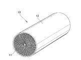
図1に示すように、排気ガス浄化用ハニカムユニット10は、金属製のメタルハニカム構造体11と、このハニカム構造体11の外周を囲む筒状の金属外筒12とからなる。
以下説明では、平板15と波板16との間が接合されている部分を接合部17と云う。また、ハニカム構造体11と金属外筒12との間が接合されている部分を接合帯18と云う。
図2〜5に示すように、平板15と波板16を巻回してなるハニカム構造体11は、ハニカム構造体11の中心軸33の周りにコアとなる平板15が巻かれ、その外方に波板16と平板15とが交互に配置される。
1つの波板の外側面27と内側面28とに各々設けた第1接合部17aと第2接合部17bとは、互いに、メタルハニカム構造体11の軸方向にオフセットして設けられている。同様に、第1接合部17cと第2接合部17dとは、互いに、メタルハニカム構造体11の軸方向にオフセットして設けられている。
接合帯18は、メタルハニカム構造体の出口側22にのみ設けられている。接合帯18は、ハニカム構造体の出口側端部34から入口側へ長さB1の長さをもつ。
波板の一方の面27a及び他方の面27bに設けられ隣接する2つの接合部17a、17b及び接合部17c、17dは、メタルハニカム構造体11の軸方向に、各々、所定の隙間δ1a、δ1bをもって配置されている。
接合部の後端36よりも後方に配置される接合帯の後端18bは、排気ガスの入口側21よりも排気ガスの出口側22に近く、ハニカムユニット10の中で最も温度が上がり難い箇所に位置する。このため、接合帯18を接合部の後端36より前方側に設ける場合に較べて、メタルハニカム構造体11と金属外筒12間の接合強度の低下を抑えることができる。
図6(a)に示すように、ハニカム構造体11は、排気ガスの入口側21と出口側22とに、平板(図2、符号15)と波板(図2、符号16)とが接合され波板16に塗布したろう材25によってろう付けされる接合部17を備えている。
従来、隣接する平板と波板とは、波板の表裏にスポット状又は千鳥状に設けた接合部によって接合され、ハニカム構造体と金属外筒とは、ハニカム構造体と金属外筒との間に設けた接合帯によって接合されている場合に、波板と平板間の接合部の長さは、接合帯の長さよりも長いものであった。
接合部の後端36よりも後方に配置される接合帯の後端18bは、排気ガスの出口側22に近く、ハニカムユニット10の中で最も温度が上がり難い箇所に位置する。このため、接合帯18を接合部の後端36より前方側に設ける場合に較べて、メタルハニカム構造体11と金属外筒12間の接合強度を保つことができる。
40μmのステンレス箔材に波付け加工を施した波板と、加工をしていない平板を準備し、波板の凸部の所定の位置に、溶媒とバインダーで調整したろう材ペーストを塗布し、平板と波板を重ねて巻き取り、Φ40×L90のハニカムコアを作成した。このコアを別に用意した外筒に挿入し、その後、真空ろう付け炉にてろう付け処理を行うことで、排気ガス用ハニカムユニットを作成した。なお、外筒とハニカムコア間もろう付け(接合帯)によって接合されている。
冷熱加振テストは、20G〜60Gの振動を加えながら、200℃〜1000℃の冷熱サイクルを1000〜2000回与える条件で行った。

40μmのステンレス箔材に波付け加工を施した波板と、加工をしていない平板を準備し、波板の凸部の所定の位置に、溶媒とバインダーで調整したろう材ペーストを塗布し、平板と波板を重ねて巻き取り、Φ40×L90のハニカムコアを作成した。このコアを別に用意した外筒に挿入し、その後、真空ろう付け炉にてろう付け処理を行うことで、排気ガス用ハニカムユニットを作成した。なお、外筒とハニカムコア間もろう付けによって接合されている。
冷熱加振テストは、20G〜60Gの振動を加えながら、200℃〜1000℃の冷熱サイクルを1000〜2000回与える条件で行った。
40μmのステンレス箔材に波付け加工を施した波板と、加工をしていない平板を準備し、波板の凸部の所定の位置に、溶媒とバインダーで調整したろう材ペーストを塗布し、平板と波板を重ねて巻き取り、Φ40×L90のハニカムコアを作成した。このコアを別に用意した外筒に挿入し、その後、真空ろう付け炉にてろう付け処理を行うことで、排気ガス用ハニカムユニットを作成した。なお、外筒とハニカムコア間もろう付けによって接合されている。
冷熱加振テストによる優劣は、テスト後のサンプルのダメージを、発生した亀裂の量で評価し、従来仕様と比較した。
冷熱加振テストは、20G〜60Gの振動を加えながら、200℃〜1000℃の冷熱サイクルを1000〜2000回与える条件で行った。
40μmのステンレス箔材に波付け加工を施した波板と、加工をしていない平板を準備し、波板の凸部の所定の位置に、溶媒とバインダーで調整したろう材ペーストを塗布し、平板と波板を重ねて巻き取り、Φ40×L90のハニカムコアを作成した。このコアを別に用意した外筒に挿入し、その後、真空ろう付け炉にてろう付け処理を行うことで、排気ガス用ハニカムユニットを作成した。なお、外筒とハニカムコア間もろう付けによって接合されている。
そして、その千鳥配置のクリアランス(δ1a、δ1b)を変化させ、冷熱加振テストにより、その優劣を評価した。なお、千鳥配置のクリアランス(δ1a、δ1b)は入口側、出口側共同じ値に設定した。
冷熱加振テストによる優劣は、テスト後のサンプルのダメージを、発生した亀裂の量で評価し、従来仕様と比較した。
冷熱加振テストは、20G〜60Gの振動を加えながら、200℃〜1000℃の冷熱サイクルを1000〜2000回与える条件で行った。
Claims (4)
- 金属外筒(12)に、平板(15)と波板(16)を重ね合わせ巻回して円筒形状にしたメタルハニカム構造体(11)を圧入して接合した排気ガス浄化用ハニカムユニットにおいて、
前記メタルハニカム構造体(11)は、前記メタルハニカム構造体(11)の両端近傍に、前記波板(16)の頂部に塗布したろう材により前記平板(15)と前記波板(16)がろう付けされる接合部(17a、17b、17c、17d)を備え、
前記1枚の波板の外側面(27)と内側面(28)とに各々設けた第1接合部(17a、17c)と第2接合部(17b、17d)とは、互いに、前記メタルハニカム構造体(11)の軸方向にオフセットして設けられ、
前記メタルハニカム構造体(11)は、前記金属外筒(12)へ接合される接合帯(18)を備え、
前記メタルハニカム構造体(11)の両端近傍に備える接合部(17a、17b、17c、17d)のうち、前記接合帯(18)と重なる側に設けた接合部(17c、17d)の前記メタルハニカム構造体(11)の軸方向のろう付け長さは、前記接合帯(18)と重ならない側に設けた接合部(17a、17b)のろう付け長さよりも長く、
前記ハニカム構造体(11)の軸方向で、前記接合帯(18)と重なる側に設けた前記接合部(17c、17d)の間に所定の長さをもつ隙間(δ1a)が形成され、
これらの隙間(δ1a)の全てが、前記接合帯(18)の軸方向の幅内に位置するように形成されることを特徴とする排気ガス浄化用ハニカムユニット。 - 前記接合帯(18)は、前記メタルハニカム構造体(11)の排気ガス出口側にのみ設けられていることを特徴とする請求項1記載の排気ガス浄化用ハニカムユニット。
- 前記メタルハニカム構造体(11)の軸方向で、前記排気ガス出口側に設けた接合帯の後端(18b)は、前記出口側に設けた接合部の後端(36)よりも後方に配置されていることを特徴とする請求項1〜2のいずれか1項記載の排気ガス浄化用ハニカムユニット。
- 前記波板の外側面(27)及び内側面(28)に設けられ隣接する前記2つの接合部(17a、17b/17c、17d)は、前記メタルハニカム構造体(11)の軸方向に、重なることなく配置されることを特徴とする請求項1記載の排気ガス浄化用ハニカムユニット。
Priority Applications (5)
| Application Number | Priority Date | Filing Date | Title |
|---|---|---|---|
| JP2011079744A JP5674531B2 (ja) | 2011-03-31 | 2011-03-31 | 排気ガス浄化用ハニカムユニット |
| EP12161374.9A EP2505805B1 (en) | 2011-03-31 | 2012-03-27 | Honeycomb unit for exhaust emission control |
| US13/435,001 US9057311B2 (en) | 2011-03-31 | 2012-03-30 | Honeycomb unit for exhaust emission control |
| BR102012007291-2A BR102012007291B1 (pt) | 2011-03-31 | 2012-03-30 | unidade alveolada para controle de emissão de gás de exaustão |
| CN201210092887.2A CN102728741B (zh) | 2011-03-31 | 2012-03-31 | 用于废气排放控制的蜂窝单元 |
Applications Claiming Priority (1)
| Application Number | Priority Date | Filing Date | Title |
|---|---|---|---|
| JP2011079744A JP5674531B2 (ja) | 2011-03-31 | 2011-03-31 | 排気ガス浄化用ハニカムユニット |
Publications (3)
| Publication Number | Publication Date |
|---|---|
| JP2012215085A JP2012215085A (ja) | 2012-11-08 |
| JP2012215085A5 JP2012215085A5 (ja) | 2014-03-13 |
| JP5674531B2 true JP5674531B2 (ja) | 2015-02-25 |
Family
ID=45929401
Family Applications (1)
| Application Number | Title | Priority Date | Filing Date |
|---|---|---|---|
| JP2011079744A Active JP5674531B2 (ja) | 2011-03-31 | 2011-03-31 | 排気ガス浄化用ハニカムユニット |
Country Status (5)
| Country | Link |
|---|---|
| US (1) | US9057311B2 (ja) |
| EP (1) | EP2505805B1 (ja) |
| JP (1) | JP5674531B2 (ja) |
| CN (1) | CN102728741B (ja) |
| BR (1) | BR102012007291B1 (ja) |
Families Citing this family (6)
| Publication number | Priority date | Publication date | Assignee | Title |
|---|---|---|---|---|
| US20160031027A1 (en) * | 2011-09-05 | 2016-02-04 | Basf Corporation | Method For Applying Brazing Material To Metal Honeycomb Matrix, Metal Honeycomb Matrix And Manufacturing Method Thereof |
| FR3008576B1 (fr) | 2013-07-17 | 2016-02-05 | Kuhn Sa | Machine de recolte de fourrage perfectionnee |
| CN104763493B (zh) * | 2014-01-08 | 2019-03-05 | 瑞德(新乡)路业有限公司 | 一种汽车尾气颗粒物捕集器及滤芯 |
| CN105705237B (zh) * | 2014-02-12 | 2018-01-30 | 新日铁住金高新材料股份有限公司 | 催化剂承载用基材 |
| CN107683176A (zh) * | 2015-10-06 | 2018-02-09 | 新日铁住金高新材料股份有限公司 | 催化剂负载用基材及催化剂载体 |
| CN114502824B (zh) * | 2019-10-08 | 2024-02-20 | 日铁化学材料株式会社 | 用于净化废气的蜂窝单元以及蜂窝单元的制造方法 |
Family Cites Families (11)
| Publication number | Priority date | Publication date | Assignee | Title |
|---|---|---|---|---|
| JP2553733B2 (ja) * | 1990-04-17 | 1996-11-13 | 昭和飛行機工業株式会社 | 耐熱構造体 |
| US5259190A (en) * | 1991-08-01 | 1993-11-09 | Corning Incorporated | Heated cellular structures |
| DE4241469A1 (de) * | 1992-12-09 | 1994-06-16 | Emitec Emissionstechnologie | Katalytischer Konverter mit zwei oder mehr Wabenkörpern in einem Mantelrohr und Verfahren zu seiner Herstellung |
| DE69416650T2 (de) * | 1993-06-07 | 1999-07-08 | Nippon Yakin Kogyo Co Ltd | Abgasreinigungsmetallträger und verfahren zur herstellung desselben |
| JP2709789B2 (ja) * | 1993-06-07 | 1998-02-04 | 日本冶金工業株式会社 | 耐熱疲労性、耐振性に優れた排ガス浄化用メタル担体及びその製造方法 |
| JPH1076165A (ja) * | 1996-09-03 | 1998-03-24 | Usui Internatl Ind Co Ltd | メタル担体 |
| CN1098970C (zh) * | 2000-01-24 | 2003-01-15 | 黄钊仁 | 废气净化用金属载体及其制法及专用装置 |
| JP3338703B1 (ja) * | 2000-10-10 | 2002-10-28 | 新日本製鐵株式会社 | ハニカム体の製造方法 |
| US7410521B2 (en) * | 2005-02-28 | 2008-08-12 | Caterpillar Inc. | Filter service system and method |
| JP4776284B2 (ja) * | 2005-06-30 | 2011-09-21 | 本田技研工業株式会社 | 排ガス浄化用メタル担体構造 |
| DE102008016148A1 (de) * | 2008-03-28 | 2009-10-01 | Emitec Gesellschaft Für Emissionstechnologie Mbh | Wabenkörper und Verfahren zur Herstellung eines gelöteten Wabenkörpers |
-
2011
- 2011-03-31 JP JP2011079744A patent/JP5674531B2/ja active Active
-
2012
- 2012-03-27 EP EP12161374.9A patent/EP2505805B1/en active Active
- 2012-03-30 US US13/435,001 patent/US9057311B2/en active Active
- 2012-03-30 BR BR102012007291-2A patent/BR102012007291B1/pt active IP Right Grant
- 2012-03-31 CN CN201210092887.2A patent/CN102728741B/zh active Active
Also Published As
| Publication number | Publication date |
|---|---|
| EP2505805B1 (en) | 2016-11-09 |
| BR102012007291A2 (pt) | 2013-06-04 |
| CN102728741A (zh) | 2012-10-17 |
| US20120247076A1 (en) | 2012-10-04 |
| CN102728741B (zh) | 2015-01-21 |
| US9057311B2 (en) | 2015-06-16 |
| EP2505805A1 (en) | 2012-10-03 |
| JP2012215085A (ja) | 2012-11-08 |
| BR102012007291B1 (pt) | 2021-02-17 |
Similar Documents
| Publication | Publication Date | Title |
|---|---|---|
| JP5674531B2 (ja) | 排気ガス浄化用ハニカムユニット | |
| JP2006118830A (ja) | 熱交換器および熱交換器の製造方法 | |
| US9416719B2 (en) | Exhaust manifold with insulation sleeve | |
| JP2012215085A5 (ja) | ||
| JP2599612B2 (ja) | 排気ガス浄化用触媒を担持するための金属製担持母体 | |
| JP2005201258A (ja) | 排気ノズルのセグメント式ベースシート及びその製作方法 | |
| KR102217605B1 (ko) | 다중 파이프 | |
| JP6433064B2 (ja) | 排気浄化装置の製造方法 | |
| JP2008064090A (ja) | 排気浄化構成要素用のハウジング | |
| EP1504817B1 (en) | Metal carrier for exhaust emission control | |
| WO2019031090A1 (ja) | 熱交換器 | |
| JPH02195096A (ja) | 伸縮管継手およびその製造方法 | |
| JPH05146685A (ja) | 排気ガス浄化用触媒及びその製造方法 | |
| JP5080306B2 (ja) | 改良された触媒反応器 | |
| JP2010125423A (ja) | 金属触媒担体 | |
| JP2009191720A (ja) | 内燃機関の排気浄化用触媒コンバータ | |
| JP6092603B2 (ja) | 排気ガス熱交換器 | |
| JP5552259B2 (ja) | 二重管構造の排気マニホールド | |
| JP2010075803A (ja) | 金属触媒担体 | |
| JP2002097942A (ja) | 触媒コンバータ | |
| JPH04148016A (ja) | 良好な耐久性を有する自動車排ガス触媒用金属担体 | |
| JPH09296723A (ja) | 二重管 | |
| JP2010106980A (ja) | 多重パイプ及び多重パイプの製造方法 | |
| JP2013043191A (ja) | 伝熱ケースの製造方法 | |
| JP4884847B2 (ja) | 排気管の接続構造 |
Legal Events
| Date | Code | Title | Description |
|---|---|---|---|
| A521 | Request for written amendment filed |
Free format text: JAPANESE INTERMEDIATE CODE: A523 Effective date: 20140120 |
|
| A621 | Written request for application examination |
Free format text: JAPANESE INTERMEDIATE CODE: A621 Effective date: 20140120 |
|
| A977 | Report on retrieval |
Free format text: JAPANESE INTERMEDIATE CODE: A971007 Effective date: 20140925 |
|
| A131 | Notification of reasons for refusal |
Free format text: JAPANESE INTERMEDIATE CODE: A131 Effective date: 20141007 |
|
| A521 | Request for written amendment filed |
Free format text: JAPANESE INTERMEDIATE CODE: A523 Effective date: 20141128 |
|
| TRDD | Decision of grant or rejection written | ||
| A01 | Written decision to grant a patent or to grant a registration (utility model) |
Free format text: JAPANESE INTERMEDIATE CODE: A01 Effective date: 20141216 |
|
| A61 | First payment of annual fees (during grant procedure) |
Free format text: JAPANESE INTERMEDIATE CODE: A61 Effective date: 20141222 |
|
| R150 | Certificate of patent or registration of utility model |
Ref document number: 5674531 Country of ref document: JP Free format text: JAPANESE INTERMEDIATE CODE: R150 |
|
| R250 | Receipt of annual fees |
Free format text: JAPANESE INTERMEDIATE CODE: R250 |
|
| R250 | Receipt of annual fees |
Free format text: JAPANESE INTERMEDIATE CODE: R250 |
|
| R250 | Receipt of annual fees |
Free format text: JAPANESE INTERMEDIATE CODE: R250 |
|
| R250 | Receipt of annual fees |
Free format text: JAPANESE INTERMEDIATE CODE: R250 |
|
| R250 | Receipt of annual fees |
Free format text: JAPANESE INTERMEDIATE CODE: R250 |
|
| R250 | Receipt of annual fees |
Free format text: JAPANESE INTERMEDIATE CODE: R250 |
|
| R250 | Receipt of annual fees |
Free format text: JAPANESE INTERMEDIATE CODE: R250 |