JP5674531B2 - Honeycomb unit for exhaust gas purification - Google Patents
Honeycomb unit for exhaust gas purification Download PDFInfo
- Publication number
- JP5674531B2 JP5674531B2 JP2011079744A JP2011079744A JP5674531B2 JP 5674531 B2 JP5674531 B2 JP 5674531B2 JP 2011079744 A JP2011079744 A JP 2011079744A JP 2011079744 A JP2011079744 A JP 2011079744A JP 5674531 B2 JP5674531 B2 JP 5674531B2
- Authority
- JP
- Japan
- Prior art keywords
- honeycomb structure
- metal
- brazing
- exhaust gas
- joint
- Prior art date
- Legal status (The legal status is an assumption and is not a legal conclusion. Google has not performed a legal analysis and makes no representation as to the accuracy of the status listed.)
- Active
Links
- 238000000746 purification Methods 0.000 title claims description 5
- 239000002184 metal Substances 0.000 claims description 96
- 238000005219 brazing Methods 0.000 claims description 94
- 239000000463 material Substances 0.000 claims description 20
- 238000004804 winding Methods 0.000 claims description 5
- 238000000034 method Methods 0.000 description 6
- 238000011156 evaluation Methods 0.000 description 5
- 239000011230 binding agent Substances 0.000 description 4
- 239000011888 foil Substances 0.000 description 4
- 239000002904 solvent Substances 0.000 description 4
- 229910001220 stainless steel Inorganic materials 0.000 description 4
- 239000010935 stainless steel Substances 0.000 description 4
- 230000008646 thermal stress Effects 0.000 description 3
- 230000000052 comparative effect Effects 0.000 description 2
- 238000001816 cooling Methods 0.000 description 2
- 230000007423 decrease Effects 0.000 description 2
- 238000010438 heat treatment Methods 0.000 description 2
- 230000035882 stress Effects 0.000 description 2
- 239000012141 concentrate Substances 0.000 description 1
- 238000010586 diagram Methods 0.000 description 1
- 230000000694 effects Effects 0.000 description 1
Images


Classifications
-
- F—MECHANICAL ENGINEERING; LIGHTING; HEATING; WEAPONS; BLASTING
- F01—MACHINES OR ENGINES IN GENERAL; ENGINE PLANTS IN GENERAL; STEAM ENGINES
- F01N—GAS-FLOW SILENCERS OR EXHAUST APPARATUS FOR MACHINES OR ENGINES IN GENERAL; GAS-FLOW SILENCERS OR EXHAUST APPARATUS FOR INTERNAL COMBUSTION ENGINES
- F01N3/00—Exhaust or silencing apparatus having means for purifying, rendering innocuous, or otherwise treating exhaust
- F01N3/08—Exhaust or silencing apparatus having means for purifying, rendering innocuous, or otherwise treating exhaust for rendering innocuous
- F01N3/10—Exhaust or silencing apparatus having means for purifying, rendering innocuous, or otherwise treating exhaust for rendering innocuous by thermal or catalytic conversion of noxious components of exhaust
- F01N3/24—Exhaust or silencing apparatus having means for purifying, rendering innocuous, or otherwise treating exhaust for rendering innocuous by thermal or catalytic conversion of noxious components of exhaust characterised by constructional aspects of converting apparatus
- F01N3/28—Construction of catalytic reactors
- F01N3/2839—Arrangements for mounting catalyst support in housing, e.g. with means for compensating thermal expansion or vibration
- F01N3/2842—Arrangements for mounting catalyst support in housing, e.g. with means for compensating thermal expansion or vibration specially adapted for monolithic supports, e.g. of honeycomb type
-
- B—PERFORMING OPERATIONS; TRANSPORTING
- B01—PHYSICAL OR CHEMICAL PROCESSES OR APPARATUS IN GENERAL
- B01J—CHEMICAL OR PHYSICAL PROCESSES, e.g. CATALYSIS OR COLLOID CHEMISTRY; THEIR RELEVANT APPARATUS
- B01J35/00—Catalysts, in general, characterised by their form or physical properties
- B01J35/50—Catalysts, in general, characterised by their form or physical properties characterised by their shape or configuration
- B01J35/56—Foraminous structures having flow-through passages or channels, e.g. grids or three-dimensional monoliths
-
- F—MECHANICAL ENGINEERING; LIGHTING; HEATING; WEAPONS; BLASTING
- F01—MACHINES OR ENGINES IN GENERAL; ENGINE PLANTS IN GENERAL; STEAM ENGINES
- F01N—GAS-FLOW SILENCERS OR EXHAUST APPARATUS FOR MACHINES OR ENGINES IN GENERAL; GAS-FLOW SILENCERS OR EXHAUST APPARATUS FOR INTERNAL COMBUSTION ENGINES
- F01N3/00—Exhaust or silencing apparatus having means for purifying, rendering innocuous, or otherwise treating exhaust
- F01N3/08—Exhaust or silencing apparatus having means for purifying, rendering innocuous, or otherwise treating exhaust for rendering innocuous
- F01N3/10—Exhaust or silencing apparatus having means for purifying, rendering innocuous, or otherwise treating exhaust for rendering innocuous by thermal or catalytic conversion of noxious components of exhaust
- F01N3/24—Exhaust or silencing apparatus having means for purifying, rendering innocuous, or otherwise treating exhaust for rendering innocuous by thermal or catalytic conversion of noxious components of exhaust characterised by constructional aspects of converting apparatus
- F01N3/28—Construction of catalytic reactors
- F01N3/2803—Construction of catalytic reactors characterised by structure, by material or by manufacturing of catalyst support
- F01N3/2807—Metal other than sintered metal
- F01N3/281—Metallic honeycomb monoliths made of stacked or rolled sheets, foils or plates
-
- F—MECHANICAL ENGINEERING; LIGHTING; HEATING; WEAPONS; BLASTING
- F01—MACHINES OR ENGINES IN GENERAL; ENGINE PLANTS IN GENERAL; STEAM ENGINES
- F01N—GAS-FLOW SILENCERS OR EXHAUST APPARATUS FOR MACHINES OR ENGINES IN GENERAL; GAS-FLOW SILENCERS OR EXHAUST APPARATUS FOR INTERNAL COMBUSTION ENGINES
- F01N2260/00—Exhaust treating devices having provisions not otherwise provided for
- F01N2260/10—Exhaust treating devices having provisions not otherwise provided for for avoiding stress caused by expansions or contractions due to temperature variations
Landscapes
- Chemical & Material Sciences (AREA)
- Engineering & Computer Science (AREA)
- Chemical Kinetics & Catalysis (AREA)
- Mechanical Engineering (AREA)
- Toxicology (AREA)
- Combustion & Propulsion (AREA)
- Health & Medical Sciences (AREA)
- General Engineering & Computer Science (AREA)
- Materials Engineering (AREA)
- Organic Chemistry (AREA)
- Exhaust Gas After Treatment (AREA)
- Catalysts (AREA)
- Laminated Bodies (AREA)
Description
本発明は、排気ガス浄化用ハニカムユニットの改良に関する。 The present invention relates to an improvement of a honeycomb unit for purifying exhaust gas.
金属外筒にメタルハニカム構造体を圧入し接合してなる排気ガス浄化用ハニカムユニットが知られている(例えば、特許文献1(図6)参照。)。 There is known an exhaust gas purifying honeycomb unit in which a metal honeycomb structure is press-fitted and joined to a metal outer cylinder (see, for example, Patent Document 1 (FIG. 6)).
特許文献1の図6に示されるように、メタル担体(以下、「排気ガス浄化用ハニカムユニット」と云う。)は、金属外筒(8)(括弧付き数字は、特許文献1記載の符号を示す。以下同じ。)に、平板と波板とを重ね合わせ巻回してなるハニカム構造体を圧入し接合してなる。
ハニカム構造体の軸方向に延びており波板と平板とを接合するろう材(3)の長さと、ハニカム構造体と金属外筒(8)との間を接合するろう材(3)の長さは同じである。
As shown in FIG. 6 of Patent Document 1, the metal carrier (hereinafter referred to as “exhaust gas purifying honeycomb unit”) is a metal outer cylinder (8) (the numbers in parentheses are the reference numerals described in Patent Document 1). The same applies to the following), and a honeycomb structure formed by stacking and winding a flat plate and a corrugated plate is press-fitted and joined.
The length of the brazing material (3) extending in the axial direction of the honeycomb structure and joining the corrugated sheet and the flat plate, and the length of the brazing material (3) joining between the honeycomb structure and the metal outer cylinder (8) The same is true.
特許文献1のメタル担体では、排気ガスがハニカム構造体を通過し、排気ガスの熱によってハニカム構造体の温度が上昇し、金属外筒(8)が遅れて温度上昇する。又、ハニカム構造体の温度が下降すると、金属外筒(8)が遅れて温度下降する。
すなわち、特許文献1のろう材の配置は、温度変化による金属外筒(8)とハニカム構造体の間の温度挙動については配慮されているものではない。
このような温度変化に、より適したろう材の配置技術が求められている。
In the metal carrier of Patent Document 1, the exhaust gas passes through the honeycomb structure, the temperature of the honeycomb structure increases due to the heat of the exhaust gas, and the temperature of the metal outer cylinder (8) increases with a delay. Further, when the temperature of the honeycomb structure decreases, the temperature of the metal outer cylinder (8) decreases with a delay.
That is, the arrangement of the brazing material in Patent Document 1 does not consider the temperature behavior between the metal outer tube (8) and the honeycomb structure due to temperature change.
There is a need for a brazing material arrangement technique that is more suitable for such temperature changes.
本発明は、排気ガス浄化用ハニカムユニットにおいて、温度変化により適したろう材の配置技術を提供することを課題とする。 It is an object of the present invention to provide a brazing material arrangement technique that is more suitable for temperature changes in an exhaust gas purification honeycomb unit.
請求項1に係る発明は、金属外筒に、平板と波板を重ね合わせ巻回して円筒形状にしたメタルハニカム構造体を圧入して接合した排気ガス浄化用ハニカムユニットにおいて、ハニカム構造体は、ハニカム構造体の両端近傍に、波板の頂部に塗布したろう材により平板に波板がろう付けされる接合部を備え、1枚の波板の外側面と内側面とに各々設けた第1接合部と第2接合部とは、互いに、ハニカム構造体の軸方向にオフセットして設けられ、ハニカム構造体は、金属外筒へ接合される接合帯を備え、ハニカム構造体の両端近傍に備える接合部のうち、接合帯と重なる側に設けた接合部のメタルハニカム構造体の軸方向のろう付け長さは、接合帯と重ならない側に設けた接合部のろう付け長さよりも長く、ハニカム構造体の軸方向で、接合帯と重なる側に設けた接合部の間に所定の長さをもつ隙間が形成され、これらの隙間の全てが、接合帯の軸方向の幅内に位置するように形成されることを特徴とする。 The invention according to claim 1 is an exhaust gas purifying honeycomb unit in which a metal honeycomb structure having a cylindrical shape formed by winding a flat plate and a corrugated sheet on a metal outer cylinder is press-fitted and joined. Near the both ends of the honeycomb structure, there are provided joint portions where the corrugated sheet is brazed to the flat plate by a brazing material applied to the top of the corrugated sheet, and are provided on the outer surface and the inner surface of one corrugated sheet, respectively. The joint portion and the second joint portion are provided to be offset from each other in the axial direction of the honeycomb structure, and the honeycomb structure includes a joining band joined to the metal outer cylinder and is provided near both ends of the honeycomb structure. among the joint, brazing length in the axial direction of the metal honeycomb core body of the joint portion provided on the side overlapping the junction zone, rather long than brazing length of the bonding portion disposed on the side that does not overlap with the junction zone, In the axial direction of the honeycomb structure, Is a gap between the bonding portion disposed in overlapping side having a predetermined length is formed, all of these gaps, characterized in that it is formed so as to be positioned within the axial width of the bonding zone.
請求項2に係る発明では、接合帯は、メタルハニカム構造体の排気ガス出口側にのみ設けられていることを特徴とする。 The invention according to claim 2 is characterized in that the joining band is provided only on the exhaust gas outlet side of the metal honeycomb structure.
請求項3に係る発明は、メタルハニカム構造体の軸方向で、排気ガス出口側に設けた接合帯の後端は、出口側に設けた接合部の後端よりも後方に配置されていることを特徴とする。 In the invention according to claim 3 , in the axial direction of the metal honeycomb structure, the rear end of the joining band provided on the exhaust gas outlet side is disposed behind the rear end of the joint provided on the outlet side. It is characterized by.
請求項4に係る発明では、波板の外側面及び内側面に設けられ隣接する2つの接合部は、メタルハニカム構造体の軸方向に、重なることなく配置されることを特徴とする。 The invention according to claim 4 is characterized in that two adjacent joint portions provided on the outer side surface and the inner side surface of the corrugated sheet are arranged in the axial direction of the metal honeycomb structure without overlapping.
請求項1に係る発明では、ハニカム構造体の両端近傍に備える接合部のうちで、接合帯と重なる側に設けた接合部のろう付け長さは、接合帯と重ならない側に設けた接合部のろう付け長さよりも長い。 In the invention according to claim 1, among the joint portions provided in the vicinity of both ends of the honeycomb structure, the brazed length of the joint portion provided on the side overlapping the joint band is the joint portion provided on the side not overlapping the joint band. Longer than brazing length.
従来、隣接する平板と波板とが接合部によって接合され、ハニカム構造体と金属外筒とが接合帯によって接合されている場合において、波板と平板間の接合部の長さは、接合帯の長さと同じ若しくは接合帯の長さよりも長いものであった。 Conventionally, in the case where adjacent flat plates and corrugated plates are joined by a joint portion, and the honeycomb structure and the metal outer cylinder are joined by a joint strip, the length of the joint portion between the corrugated plate and the flat plate is The length was equal to or longer than the length of the joining band.
この点、本発明では、ハニカム構造体は、金属外筒へ接合される接合帯を備え、この接合帯と重なる側に設けた接合部のろう付け長さを長くした。より大きな力がかかる接合帯の側に位置する接合部のろう付け長さを長くしたので、メタルハニカム構造体の剛性を高めることができる。加えて、メタルハニカム構造体の変形を抑制することができる。 In this regard, in the present invention, the honeycomb structure includes a joining band joined to the metal outer cylinder, and the brazing length of the joining portion provided on the side overlapping the joining band is increased. Since the brazing length of the joint located on the side of the joining band to which a greater force is applied is increased, the rigidity of the metal honeycomb structure can be increased. In addition, deformation of the metal honeycomb structure can be suppressed.
さらに、大きな接合強度が求められる金属外筒とハニカム構造体との接合帯のろう付け長さを十分に長くしたので、温度変化により適した配置となる。
その一方で、金属外筒の影響を受け難い接合帯とは反対側に位置する接合部は、そのろう付け長さを短くしたので、ろう材の使用量を節約することができる。
従って、本発明によれば、温度変化により適したろう材が配置されている排気ガス浄化用ハニカムユニットが提供される。
Furthermore, since the brazing length of the joining band between the metal outer cylinder and the honeycomb structure, which require high joining strength, is sufficiently long, the arrangement is more suitable for temperature changes.
On the other hand, the joining portion located on the side opposite to the joining band which is not easily affected by the metal outer cylinder has a shortened brazing length, so that the amount of brazing material used can be saved.
Therefore, according to the present invention, there is provided an exhaust gas purifying honeycomb unit in which a brazing material more suitable for temperature change is arranged.
請求項2に係る発明では、接合帯がメタルハニカム構造体の排気ガス出口側にのみ設けられているので、メタハニカム構造体の温度が上昇したときに、メタルハニカム構造体を金属外筒の前方に膨張移動させることができ、メタルハニカム構造体への負担を減らすことができる。 In the invention according to claim 2 , since the joining band is provided only on the exhaust gas outlet side of the metal honeycomb structure, when the temperature of the meta honeycomb structure rises, the metal honeycomb structure is moved forward of the metal outer cylinder. And the burden on the metal honeycomb structure can be reduced.
請求項3に係る発明では、メタルハニカム構造体の排気ガス出口側に設けた接合帯の後端は、接合部の後端よりも後方に配置されている。
接合部の後端よりも後方に配置される接合帯の後端は、排気ガスの出口側に近く、ハニカムユニットの中で最も温度が上がり難い箇所に位置する。このため、接合帯を接合部の後端より前方側に設ける場合に較べて、メタルハニカム構造体と金属外筒間の接合強度を保つことができる。
In the invention which concerns on Claim 3 , the rear end of the joining band provided in the exhaust-gas outlet side of a metal honeycomb structure is arrange | positioned back rather than the rear end of a junction part.
The rear end of the joining band disposed behind the rear end of the joint is close to the exhaust gas outlet side, and is located at the place where the temperature is most difficult to rise in the honeycomb unit. For this reason, the joining strength between the metal honeycomb structure and the metal outer cylinder can be maintained as compared with the case where the joining band is provided in front of the rear end of the joining portion.
請求項4に係る発明では、波板の外側面と内側面に設けられる2つの接合部同士は重ならないようにすると共に、隣接する接続部を重ならないように設定したので、隣接する2つの接合部を重ねる場合に較べて、延びが許容される。このため、平板を含めたメタルハニカム構造体に力が掛かり難くなり、排気ガス浄化用ハニカムユニットの耐久性を高めることができる。 In the invention according to claim 4 , the two joint portions provided on the outer side surface and the inner side surface of the corrugated sheet are not overlapped with each other, and the adjacent connection portions are not overlapped with each other. The extension is allowed as compared with the case of overlapping the parts. For this reason, it becomes difficult to apply force to the metal honeycomb structure including the flat plate, and the durability of the exhaust gas purifying honeycomb unit can be improved.
以下、本発明の実施の形態について、詳細に説明する。 Hereinafter, embodiments of the present invention will be described in detail.
先ず、本発明の実施例1を図面に基づいて説明する。
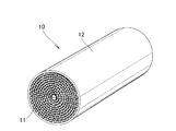
図1に示すように、排気ガス浄化用ハニカムユニット10は、金属製のメタルハニカム構造体11と、このハニカム構造体11の外周を囲む筒状の金属外筒12とからなる。
First, Embodiment 1 of the present invention will be described with reference to the drawings.
As shown in FIG. 1, the exhaust gas
図1、図4〜5に示すように、金属製のハニカム構造体11は、金属製の平板15に金属製の波板16を重ね合わせ、渦巻き状に巻回して製造した部材である。図において、金属製のハニカム構造体11を筒状の金属外筒12に圧入した後接合した状態が示されている。
As shown in FIGS. 1 and 4 to 5 , the
ハニカム構造体11は、平板15と波板16とを交互に重ね合わせ、平板15と波板16との間を接合してなる。ハニカム構造体11は、金属外筒12との間で接合固着される。
以下説明では、平板15と波板16との間が接合されている部分を接合部17と云う。また、ハニカム構造体11と金属外筒12との間が接合されている部分を接合帯18と云う。
The
In the following description, a portion where the
次に、ハニカム構造体の断面構造について説明する。
図2〜5に示すように、平板15と波板16を巻回してなるハニカム構造体11は、ハニカム構造体11の中心軸33の周りにコアとなる平板15が巻かれ、その外方に波板16と平板15とが交互に配置される。
Next, the cross-sectional structure of the honeycomb structure will be described.
As shown in FIGS. 2 to 5 , in the
平板15と波板16との接合については、ハニカム構造体11の一部を構成し排気ガスが入る側に設けた入口側21寄りの位置23と排気ガスが出る側に設けた出口側22寄りの位置24とに、波板16の頂部に塗布したろう材をろう付けすることによって平板15に波板16が接合される接合部17を備える。
As for the joining of the
すなわち、メタルハニカム構造体11は、メタルハニカム構造体11の両端23、24近傍にて、波板16の頂部に塗布したろう材により平板15と波板16がろう付けされる接合部17a、17b、17c、17dを備えている。
1つの波板の外側面27と内側面28とに各々設けた第1接合部17aと第2接合部17bとは、互いに、メタルハニカム構造体11の軸方向にオフセットして設けられている。同様に、第1接合部17cと第2接合部17dとは、互いに、メタルハニカム構造体11の軸方向にオフセットして設けられている。
In other words, the
The first joint portion 17 a and the second joint portion 17 b provided on the outer side surface 27 and the inner side surface 28 of one corrugated plate are provided offset from each other in the axial direction of the
図3に示すように、ハニカム構造体11は、ろう材25によって金属外筒12へ接合される接合帯18を備えている。
接合帯18は、メタルハニカム構造体の出口側22にのみ設けられている。接合帯18は、ハニカム構造体の出口側端部34から入口側へ長さB1の長さをもつ。
As shown in FIG. 3 , the
The joining
図4に戻り、ハニカム構造体の両端近傍に位置する入口側21寄りの位置23と出口側22寄りの位置24とに備える接合部17a、17b、17c、17dのうち、接合帯18と重なる側に設けた接合部17c、17dのメタルハニカム構造体11の軸方向のろう付け長さ(A1−δ1a)は、各々、接合帯18と重ならない側に設けた接合部17のろう付け長さ(A2−δ1b)よりも長い((A2−δ1b)<(A1−δ1a))。ここで、δ1a、δ1bはハニカム構造体軸方向で2つの接合部間のすき間である。
Returning to FIG. 4, of the joining portions 17 a, 17 b, 17 c, and 17 d provided at the position 23 near the
また、メタルハニカム構造体11の軸方向で、出口側22に設けた接合帯の後端18bは、出口側に設けた接合部の後端36よりも後方に配置されている。
波板の一方の面27a及び他方の面27bに設けられ隣接する2つの接合部17a、17b及び接合部17c、17dは、メタルハニカム構造体11の軸方向に、各々、所定の隙間δ1a、δ1bをもって配置されている。
Further, in the axial direction of the
Two adjacent joint portions 17a, 17b and joint portions 17c, 17d provided on one
従来、隣接する平板と波板とは、接合部によって接合され、ハニカム構造体と金属外筒とは、接合帯によって接合されていた。この場合に、波板と平板間の接合部の長さは、接合帯の長さよりも長いものであった。 Conventionally, adjacent flat plates and corrugated plates are joined by joints, and honeycomb structures and metal outer cylinders are joined by joint bands. In this case, the length of the joint between the corrugated sheet and the flat plate was longer than the length of the joint band.
この点、本発明では、ハニカム構造体11は、金属筒体12へ接合される接合帯18を備え、この接合帯18と重なる側に設けた接合部17のろう付け長さを長くした((A2−δ1b)<(A1−δ1a))。より大きな力がかかる接合帯18の側に位置する接合部17のろう付け長さを長くしたので、メタルハニカム構造体11の剛性を高めると共に、メタルハニカム構造体11の変形を抑制することができる。
In this regard, in the present invention, the
また、接合帯18は、メタルハニカム構造体の出口側22にのみ設けられているので、メタハニカム構造体11の温度が上昇したときに、メタルハニカム構造体11を金属筒体12の前方に膨張移動させることができ、メタルハニカム構造体11への負担を減らすことができる。
Further, since the joining
さらに、メタルハニカム構造体11の出口側22に設けた接合帯の後端18bは、接合部の後端36よりも後方に配置されている。
接合部の後端36よりも後方に配置される接合帯の後端18bは、排気ガスの入口側21よりも排気ガスの出口側22に近く、ハニカムユニット10の中で最も温度が上がり難い箇所に位置する。このため、接合帯18を接合部の後端36より前方側に設ける場合に較べて、メタルハニカム構造体11と金属外筒12間の接合強度の低下を抑えることができる。
Furthermore, the
The
さらにまた、隣接する接続部17a、17bの間は隙間δ1で離間させたので、隣接する2つの接合部17a、17bを重ねる場合に較べて、延びが許容される。このため、平板15を含めたメタルハニカム構造体11に力が掛かり難くなり、排気ガス浄化用ハニカムユニット10の耐久性を高めることができる。
Furthermore, since the adjacent connection portions 17a and 17b are separated by the gap δ1, the extension is allowed as compared with the case where the two adjacent joint portions 17a and 17b are overlapped. For this reason, it becomes difficult to apply force to the
次に、本発明の実施例2を図面に基づいて説明する。
図6(a)に示すように、ハニカム構造体11は、排気ガスの入口側21と出口側22とに、平板(図2、符号15)と波板(図2、符号16)とが接合され波板16に塗布したろう材25によってろう付けされる接合部17を備えている。
Next, a second embodiment of the present invention will be described with reference to the drawings.
As shown in FIG. 6 (a), in the
メタルハニカム構造体11の両端近傍にて、波板16の頂部に塗布したろう材により平板15と波板16とを接合する接合部17a、17b、17c、17dにおいて、1つの波板の外側面27と内側面28とに各々設けた第1接合部17aと第2接合部17bとは、互いに、メタルハニカム構造体11の軸方向にオフセットして設けられている。同様に、第1接合部17cと第2接合部17dとは、互いに、メタルハニカム構造体11の軸方向にオフセットして設けられている。
In the joints 17a, 17b, 17c, and 17d that join the
図6(b)に示すように、ハニカム構造体11は、金属外筒の内壁12bに設けたろう材によって接合される接合帯18を備え、メタルハニカム構造体11の軸方向で、接合帯18は接合部17に全て重なり、且つ、接合帯18のろう付け長さB2は、接合部17のろう付け長さA2に較べて長い(A2<B2)。
As shown in FIG. 6 (b), the
図7に示すように、接合帯18は接合部17に重なり、且つ、接合帯18のろう付け長さB2は、接合部17のろう付け長さ(A1−δ1a)に較べて長い。
従来、隣接する平板と波板とは、波板の表裏にスポット状又は千鳥状に設けた接合部によって接合され、ハニカム構造体と金属外筒とは、ハニカム構造体と金属外筒との間に設けた接合帯によって接合されている場合に、波板と平板間の接合部の長さは、接合帯の長さよりも長いものであった。
As shown in FIG. 7, the joining
Conventionally, adjacent flat plates and corrugated plates are joined by spotted or staggered joints on the front and back of the corrugated plate, and the honeycomb structure and the metal outer cylinder are between the honeycomb structure and the metal outer cylinder. In the case of being bonded by the bonding band provided on the plate, the length of the bonding portion between the corrugated sheet and the flat plate was longer than the length of the bonding band.
この点、本発明では、ハニカム構造体11は、金属外筒12へ接合される接合帯18を備え、この接合帯18は接合部17に重なり、且つ、接合帯18のろう付け長さB2は、接合部17のろう付け長さ(A1−δ1a)に較べて長いものとした((A1−δ1a)<B2)。メタルハニカム構造体11の軸方向で、波板16の接合部17は、接合帯18に全てが重なるように設けたので、メタルハニカム構造体11の剛性を高めると共に、メタルハニカム構造体11の変形を抑制することができる。
In this regard, in the present invention, the
接合帯18は、メタルハニカム構造体の出口側22にのみ設けられているので、メタハニカム構造体11の温度が上昇したときに、メタルハニカム構造体11を金属外筒12の前方に膨張移動させることができ、メタルハニカム構造体11への負担を減らすことができる。
Since the joining
さらに、メタルハニカム構造体の出口側22に設けた接合帯の後端18bは、接合部の後端36よりも後方に配置されている。
接合部の後端36よりも後方に配置される接合帯の後端18bは、排気ガスの出口側22に近く、ハニカムユニット10の中で最も温度が上がり難い箇所に位置する。このため、接合帯18を接合部の後端36より前方側に設ける場合に較べて、メタルハニカム構造体11と金属外筒12間の接合強度を保つことができる。
Furthermore, the
The
さらにまた、隣接する接続部17a、17bの間は隙間δ1aで離間させたので、隣接する2つの接合部17a、17bを重ねる場合に較べて、延びが許容される。このため、平板15を含めたメタルハニカム構造体11に力が掛かり難くなり、排気ガス浄化用ハニカムユニット10の耐久性を高めることができる。
Furthermore, since the adjacent connection portions 17a and 17b are separated by the gap δ1a, the extension is allowed as compared with the case where the two adjacent joint portions 17a and 17b are overlapped. For this reason, it becomes difficult to apply force to the
以下、上記構成及び作用を裏付けるデータを実験例1〜4を通じて説明する。なお、本発明は実験例に限定されるものではない。 Hereinafter, data supporting the above configuration and operation will be described through Experimental Examples 1 to 4. Note that the present invention is not limited to experimental examples.
(実験例1)
40μmのステンレス箔材に波付け加工を施した波板と、加工をしていない平板を準備し、波板の凸部の所定の位置に、溶媒とバインダーで調整したろう材ペーストを塗布し、平板と波板を重ねて巻き取り、Φ40×L90のハニカムコアを作成した。このコアを別に用意した外筒に挿入し、その後、真空ろう付け炉にてろう付け処理を行うことで、排気ガス用ハニカムユニットを作成した。なお、外筒とハニカムコア間もろう付け(接合帯)によって接合されている。
(Experimental example 1)
Prepare a corrugated sheet that has been corrugated on a 40 μm stainless steel foil and a flat sheet that has not been processed, and apply a brazing material paste adjusted with a solvent and a binder to a predetermined position on the convex part of the corrugated sheet, A flat plate and a corrugated plate were piled up and wound to prepare a honeycomb core of Φ40 × L90. The core was inserted into a separately prepared outer cylinder, and then a brazing process was performed in a vacuum brazing furnace to produce an exhaust gas honeycomb unit. The outer cylinder and the honeycomb core are also joined by brazing (joining band).
コアのろう付け(接合部)は、両端部より4mmの位置から入口側、出口側ともに所定の配置および長さとし、コアと外筒間のろう付け(接合帯)は、コア出口側端部より始まり、長さ20mmとした。また、波板の外側、内側で隣り合うろう付け部は、軸方向にずれて配置されており(これを千鳥配置と言う)、そのクリアランスは、2mmに設定した。なお、コアの状態で、波板の外側に位置するろう付け部を出口側に配置した。 The brazing (joining part) of the core has a predetermined arrangement and length on both the inlet side and the outlet side from a position 4 mm from both ends, and the brazing (joining band) between the core and the outer cylinder is from the end part on the core outlet side. Beginning with a length of 20 mm. Further, the brazing portions adjacent to each other on the outside and inside of the corrugated plate are arranged so as to be shifted in the axial direction (this is called staggered arrangement), and the clearance is set to 2 mm. In addition, the brazing part located in the outer side of a corrugated sheet in the state of the core was arrange | positioned at the exit side.
冷熱加振テストによる強度は、テスト後のサンプルのダメージを、発生した亀裂の量で評価し、従来仕様と比較した。セル変形も同様に従来仕様と比較した。
冷熱加振テストは、20G〜60Gの振動を加えながら、200℃〜1000℃の冷熱サイクルを1000〜2000回与える条件で行った。
The strength by the thermal vibration test was evaluated by comparing the amount of cracks that occurred in the sample after the test with the conventional specification. The cell deformation was also compared with the conventional specification.
The cold heat test was performed under the condition of applying a heat cycle of 200 ° C. to 1000 ° C. 1000 to 2000 times while applying a vibration of 20G to 60G.
表1は、実験例1について、入口側ろう付け長さ、出口側ろう付け長さを変化させたとき、冷熱加振テスト結果(強度、セル変形)及びろう使用量を評価し、これらの3つの評価に基づいて総合判定を行ったことを示す。表中、Jは実施例データ、Hは比較例データである。 Table 1 shows the results of evaluating the thermal vibration test results (strength, cell deformation) and the amount of brazing used in Experimental Example 1 when the inlet side brazing length and the outlet side brazing length were changed. It shows that comprehensive judgment was performed based on one evaluation. In the table, J is an example data, and H is a comparative example data.

出口側のろう付け長さ(a1、a2)は、7mm以上必要であり、より好ましくは10mmである。入口側のろう付け長さ(b1、b2)は、強度に与える影響はほとんど無く、セル変形観点から7mm以上では、やや変形が大きくなる。ただし1mmでは、部分的にろう付け不良が発生したため、総合判定は×(NG)である。なお、ろう付け長さは、短いほうがろう材の使用量の低減が図れるため、コスト面で有利となる。したがって入口側のろう付け長さは、7mm以下であり、より好ましくは2mm〜5mmである。 The brazing length (a1, a2) on the outlet side is required to be 7 mm or more, and more preferably 10 mm. The brazing lengths (b1, b2) on the inlet side have almost no influence on the strength, and the deformation becomes somewhat large at 7 mm or more from the viewpoint of cell deformation. However, at 1 mm, since brazing failure partially occurred, the comprehensive judgment is x (NG). A shorter brazing length is advantageous in terms of cost because the amount of brazing material used can be reduced. Therefore, the brazing length on the inlet side is 7 mm or less, more preferably 2 mm to 5 mm.
(実験例2)
40μmのステンレス箔材に波付け加工を施した波板と、加工をしていない平板を準備し、波板の凸部の所定の位置に、溶媒とバインダーで調整したろう材ペーストを塗布し、平板と波板を重ねて巻き取り、Φ40×L90のハニカムコアを作成した。このコアを別に用意した外筒に挿入し、その後、真空ろう付け炉にてろう付け処理を行うことで、排気ガス用ハニカムユニットを作成した。なお、外筒とハニカムコア間もろう付けによって接合されている。
(Experimental example 2)
Prepare a corrugated sheet that has been corrugated on a 40 μm stainless steel foil and a flat sheet that has not been processed, and apply a brazing material paste adjusted with a solvent and a binder to a predetermined position on the convex part of the corrugated sheet, A flat plate and a corrugated plate were piled up and wound to prepare a honeycomb core of Φ40 × L90. The core was inserted into a separately prepared outer cylinder, and then a brazing process was performed in a vacuum brazing furnace to produce an exhaust gas honeycomb unit. The outer cylinder and the honeycomb core are also joined by brazing.
コアのろう付け(接合部)は、両端部より4mmの位置から入口側ろう付け長さ5mm千鳥配置、出口側10mm千鳥配置とし、コアの状態で、波板の外側に位置するろう付け部を出口側に配置した。なお、その千鳥配置のクリアランス(δ1a、δ1b)は、入口側、出口側共に2mmに設定した。 The brazing (joining part) of the core has a staggered arrangement of 5 mm staggered on the inlet side and a staggered arrangement of 10 mm on the outlet side from a position 4 mm from both ends, and the brazed part located outside the corrugated sheet in the state of the core. Arranged on the exit side. The staggered clearances (δ1a, δ1b) were set to 2 mm on both the inlet side and the outlet side.
このコアと外筒間のろう付け(接合帯)の長さ(B1)を種々変化させたサンプルを準備し、冷熱加振テストにより、その優劣を評価した。なお、コア/外筒間のろう付け長さ(B1)は、コア端部より所定の長さとした。 Samples in which the length (B1) of brazing (joining band) between the core and the outer cylinder was variously prepared were prepared, and the superiority or inferiority thereof was evaluated by a cooling / heating vibration test. In addition, the brazing length (B1) between the core and the outer cylinder was set to a predetermined length from the end of the core.
冷熱加振テストによる優劣は、テスト後のサンプルのダメージを、発生した亀裂の量で評価し、従来仕様と比較した。セル変形も同様に従来仕様と比較した。
冷熱加振テストは、20G〜60Gの振動を加えながら、200℃〜1000℃の冷熱サイクルを1000〜2000回与える条件で行った。
The superiority or inferiority of the thermal vibration test was evaluated by comparing the amount of cracks that occurred in the sample after the test with the conventional specification. The cell deformation was also compared with the conventional specification.
The cold heat test was performed under the condition of applying a heat cycle of 200 ° C. to 1000 ° C. 1000 to 2000 times while applying a vibration of 20G to 60G.
表2は、実験例2について、コア/外筒間入口側ろう付け長さ、コア/外筒間出口側ろう付け長さ(B1)を変化させたとき、冷熱加振テスト結果(強度、セル変形)及びろう使用量を評価し、これらの3つの評価に基づいて総合判定を行ったことを示す。表中、Jは実施例データ、Hは比較例データである。 Table 2 shows the results of the thermal vibration test (intensity, cell) when the core / outer cylinder inlet side brazing length and the core / outer cylinder outlet side brazing length (B1) were changed for Experimental Example 2. Deformation) and the amount of brazing used are evaluated, and it is shown that comprehensive judgment is made based on these three evaluations. In the table, J is an example data, and H is a comparative example data.
コア/外筒間ろう付けを入口側、出口側共に行ったサンプルは、熱応力をコア伸びによって逃がすことができないため、強度面で大きく劣る結果となった。また、コア/外筒間ろう付けを入口側のみに行ったサンプルは、セル変形が著しく発生し、従来仕様より劣っていた。コア/外筒間のろう付けは、出口側のみに行う仕様が本発明である。 The sample in which the core / outer cylinder brazing was performed on both the inlet side and the outlet side had a result that the thermal stress could not be released by the core elongation, and the strength was greatly inferior. In addition, the sample in which the core / outer tube brazing was performed only on the inlet side caused remarkable cell deformation and was inferior to the conventional specification. The specification that the brazing between the core and the outer cylinder is performed only on the outlet side is the present invention.
次にコア/外筒間のろう付け長さであるが、15mm以上で良好な強度を示したが、10mm以下では強度が十分ではない。その原因を調べたところ、コアろう付け部長さに対してコア/外筒間ろう付け長さが同じかまたは短いと、ダメージがコア/外筒間ろう付け部に集中して発生することが判明した。したがって、コア/外筒間ろう付け部長さは、コアろう付け部長さより長くなくてはならない。 Next, the brazing length between the core and the outer cylinder showed good strength at 15 mm or more, but the strength was insufficient at 10 mm or less. As a result of investigating the cause, it was found that when the core / outer cylinder brazing length is the same or shorter than the core brazing part length, damage is concentrated on the core / outer cylinder brazing part. did. Therefore, the length of the brazing portion between the core and the outer cylinder must be longer than the length of the core brazing portion.
(実験例3)
40μmのステンレス箔材に波付け加工を施した波板と、加工をしていない平板を準備し、波板の凸部の所定の位置に、溶媒とバインダーで調整したろう材ペーストを塗布し、平板と波板を重ねて巻き取り、Φ40×L90のハニカムコアを作成した。このコアを別に用意した外筒に挿入し、その後、真空ろう付け炉にてろう付け処理を行うことで、排気ガス用ハニカムユニットを作成した。なお、外筒とハニカムコア間もろう付けによって接合されている。
(Experimental example 3)
Prepare a corrugated sheet that has been corrugated on a 40 μm stainless steel foil and a flat sheet that has not been processed, and apply a brazing material paste adjusted with a solvent and a binder to a predetermined position on the convex part of the corrugated sheet, A flat plate and a corrugated plate were piled up and wound to prepare a honeycomb core of Φ40 × L90. The core was inserted into a separately prepared outer cylinder, and then a brazing process was performed in a vacuum brazing furnace to produce an exhaust gas honeycomb unit. The outer cylinder and the honeycomb core are also joined by brazing.
コアのろう付け(接合部)は、両端部より4mmの位置から入口側ろう付け長さ5mm千鳥配置、出口側10mm千鳥配置とし、コアの状態で、波板の外側に位置するろう付け部を出口側に配置した。なお、その千鳥配置のクリアランスは、入口側、出口側共に2mmに設定した。 The brazing (joining part) of the core has a staggered arrangement of 5 mm staggered on the inlet side and a staggered arrangement of 10 mm on the outlet side from a position 4 mm from both ends, and the brazed part located outside the corrugated sheet in the state of the core. Arranged on the exit side. The clearance of the staggered arrangement was set to 2 mm on both the inlet side and the outlet side.
このコアと外筒間のろう付け(接合帯)は出口側のみで長さは20mmとし、その位置をコア端部から変化させて、冷熱加振テストにより、その優劣を評価した。
冷熱加振テストによる優劣は、テスト後のサンプルのダメージを、発生した亀裂の量で評価し、従来仕様と比較した。
冷熱加振テストは、20G〜60Gの振動を加えながら、200℃〜1000℃の冷熱サイクルを1000〜2000回与える条件で行った。
The brazing (joining band) between the core and the outer cylinder was 20 mm in length only on the outlet side, the position was changed from the end of the core, and the superiority or inferiority was evaluated by a thermal vibration test.
The superiority or inferiority of the thermal vibration test was evaluated by comparing the amount of cracks that occurred in the sample after the test with the conventional specification.
The cold heat test was performed under the condition of applying a heat cycle of 200 ° C. to 1000 ° C. 1000 to 2000 times while applying a vibration of 20G to 60G.
表3は、実験例について、コア/外筒間ろう付け、コア出口端部からの距離を変化させたとき、冷熱加振テスト結果(強度、セル変形)及びろう使用量を評価し、これらの3つの評価に基づいて総合判定を行ったことを示す。 Table 3 shows the results of evaluation of the thermal vibration test results (strength, cell deformation) and the amount of brazing used when the distance from the core / outer cylinder brazing and the core exit end was changed. It shows that comprehensive judgment was performed based on three evaluations.
熱応力を伸びによって逃がす必要があるため、コア/外筒間ろう付け位置は、できる限りコア出口側に設定したほうが良いことがわかる。さらに、コアろう付け部の端部とコア/外筒間ろう付けの端部が重なると、応力が集中し強度低下を招くため、重なることを避ける必要がある。したがって、コア/外筒間ろう付けの端部は、コアろう付け部の端部よりも後方に設定される。本発明の場合には、コア/外筒間ろう付け部の端部は、コア端部から5mm未満の間に設定されることとなる。 Since it is necessary to release the thermal stress by stretching, it can be seen that it is better to set the brazing position between the core and the outer cylinder as close to the core outlet as possible. Furthermore, if the end portion of the core brazing portion and the end portion of the brazing between the core and the outer cylinder overlap, stress concentrates and the strength is reduced, so it is necessary to avoid overlapping. Therefore, the end of the core / outer cylinder brazing is set behind the end of the core brazing. In the case of the present invention, the end of the core / outer cylinder brazing portion is set to be less than 5 mm from the end of the core.
(実験例4)
40μmのステンレス箔材に波付け加工を施した波板と、加工をしていない平板を準備し、波板の凸部の所定の位置に、溶媒とバインダーで調整したろう材ペーストを塗布し、平板と波板を重ねて巻き取り、Φ40×L90のハニカムコアを作成した。このコアを別に用意した外筒に挿入し、その後、真空ろう付け炉にてろう付け処理を行うことで、排気ガス用ハニカムユニットを作成した。なお、外筒とハニカムコア間もろう付けによって接合されている。
(Experimental example 4)
Prepare a corrugated sheet that has been corrugated on a 40 μm stainless steel foil and a flat sheet that has not been processed, and apply a brazing material paste adjusted with a solvent and a binder to a predetermined position on the convex part of the corrugated sheet, A flat plate and a corrugated plate were piled up and wound to prepare a honeycomb core of Φ40 × L90. The core was inserted into a separately prepared outer cylinder, and then a brazing process was performed in a vacuum brazing furnace to produce an exhaust gas honeycomb unit. The outer cylinder and the honeycomb core are also joined by brazing.
コアのろう付け(接合部)は、両端部より4mmの位置から入口側ろう付け長さ5mm千鳥配置、出口側10mm千鳥配置とし、コアの状態で、波板の外側に位置するろう付け部を出口側に配置した。 The brazing (joining part) of the core has a staggered arrangement of 5 mm staggered on the inlet side and a staggered arrangement of 10 mm on the outlet side from a position 4 mm from both ends, and the brazed part located outside the corrugated sheet in the state of the core. Arranged on the exit side.
このコアと外筒間のろう付け(接合帯)は出口側のみで長さは20mmとし、その位置はコア端部からとした。
そして、その千鳥配置のクリアランス(δ1a、δ1b)を変化させ、冷熱加振テストにより、その優劣を評価した。なお、千鳥配置のクリアランス(δ1a、δ1b)は入口側、出口側共同じ値に設定した。
冷熱加振テストによる優劣は、テスト後のサンプルのダメージを、発生した亀裂の量で評価し、従来仕様と比較した。
冷熱加振テストは、20G〜60Gの振動を加えながら、200℃〜1000℃の冷熱サイクルを1000〜2000回与える条件で行った。
The brazing (joining band) between the core and the outer cylinder was only on the outlet side, the length was 20 mm, and the position was from the end of the core.
Then, the clearance (δ1a, δ1b) of the staggered arrangement was changed, and the superiority or inferiority was evaluated by a cooling / heating vibration test. The staggered clearances (δ1a, δ1b) were set to the same value on the inlet side and the outlet side.
The superiority or inferiority of the thermal vibration test was evaluated by comparing the amount of cracks that occurred in the sample after the test with the conventional specification.
The cold heat test was performed under the condition of applying a heat cycle of 200 ° C. to 1000 ° C. 1000 to 2000 times while applying a vibration of 20G to 60G.
表4は、実験例4について、千鳥配置した隣り合う接合部間のクリアランス(δ1a、δ1b)を変化させたとき、冷熱加振テスト結果(強度、セル変形)及びろう使用量を評価し、これらの3つの評価に基づいて総合判定を行ったことを示す。 Table 4 evaluates the results of the thermal vibration test (strength, cell deformation) and the amount of brazing used when the clearance (δ1a, δ1b) between adjacent joints arranged in a staggered manner was changed for Experimental Example 4. It shows that comprehensive judgment was performed based on these three evaluations.
千鳥配置のろう付けがラップしていると、ダメージによる亀裂の発生が、ろう付け同士の間で進展するため、強度が劣る。これは、ラップした部分のコア剛性が高まるため、応力の集中が発生するためと考える。クリアランス0〜4mmでは、十分な強度を示したが、クリアランス(δ1a、δ1b)がより大きくなると、コアの軸方向での熱応力を伸びで逃がす効果が抑制されるため、強度が低下する。最適なクリアランスは2mmであった。したがって千鳥配置のろう付け部のクリアランス(δ1a、δ1b)は、0〜4mmに設定され、より好ましくは1〜3mmである。 If the staggered brazing is wrapped, cracks due to damage develop between the brazings, resulting in poor strength. This is considered because stress concentration occurs because the core rigidity of the wrapped portion increases. The clearance of 0 to 4 mm showed a sufficient strength. However, when the clearance (δ1a, δ1b) becomes larger, the effect of releasing the thermal stress in the axial direction of the core by elongation is suppressed, and the strength is lowered. The optimum clearance was 2 mm. Accordingly, the clearances (δ1a, δ1b) of the staggered brazing portions are set to 0 to 4 mm, and more preferably 1 to 3 mm.
本発明は、排気ガス浄化用ハニカムユニットに好適である。 The present invention is suitable for an exhaust gas purifying honeycomb unit.
10…(排気ガス浄化用)ハニカムユニット、11…メタルハニカム構造体、12…金属外筒(金属筒体)、12b…金属外筒の内壁、15…平板、16…波板、17a、17c…(第1)接合部、17b、17d…(第2)接合部、18…接合帯、18b…接合帯の後端、27…波板の一方の面(外側面)、28…波板の他方の面(内側面)、36…接合部の後端。
DESCRIPTION OF
Claims (4)
前記メタルハニカム構造体(11)は、前記メタルハニカム構造体(11)の両端近傍に、前記波板(16)の頂部に塗布したろう材により前記平板(15)と前記波板(16)がろう付けされる接合部(17a、17b、17c、17d)を備え、
前記1枚の波板の外側面(27)と内側面(28)とに各々設けた第1接合部(17a、17c)と第2接合部(17b、17d)とは、互いに、前記メタルハニカム構造体(11)の軸方向にオフセットして設けられ、
前記メタルハニカム構造体(11)は、前記金属外筒(12)へ接合される接合帯(18)を備え、
前記メタルハニカム構造体(11)の両端近傍に備える接合部(17a、17b、17c、17d)のうち、前記接合帯(18)と重なる側に設けた接合部(17c、17d)の前記メタルハニカム構造体(11)の軸方向のろう付け長さは、前記接合帯(18)と重ならない側に設けた接合部(17a、17b)のろう付け長さよりも長く、
前記ハニカム構造体(11)の軸方向で、前記接合帯(18)と重なる側に設けた前記接合部(17c、17d)の間に所定の長さをもつ隙間(δ1a)が形成され、
これらの隙間(δ1a)の全てが、前記接合帯(18)の軸方向の幅内に位置するように形成されることを特徴とする排気ガス浄化用ハニカムユニット。 In an exhaust gas purifying honeycomb unit in which a metal honeycomb structure (11) having a cylindrical shape formed by overlapping and winding a flat plate (15) and a corrugated plate (16) on a metal outer cylinder (12) is joined.
In the metal honeycomb structure (11), the flat plate (15) and the corrugated sheet (16) are formed by brazing material applied to the top of the corrugated sheet (16) in the vicinity of both ends of the metal honeycomb structure (11). Comprising joints (17a, 17b, 17c, 17d) to be brazed;
The first joint portion (17a, 17c) and the second joint portion (17b, 17d) respectively provided on the outer surface (27) and the inner surface (28) of the one corrugated plate are mutually connected to the metal honeycomb. Provided offset in the axial direction of the structure (11),
The metal honeycomb structure (11) includes a joining band (18) joined to the metal outer cylinder (12),
Of the joint portions (17a, 17b, 17c, 17d) provided in the vicinity of both ends of the metal honeycomb structure (11), the metal honeycomb of the joint portion (17c, 17d) provided on the side overlapping the joint band (18). The brazing length in the axial direction of the structure (11) is longer than the brazing length of the joint portions (17a, 17b) provided on the side that does not overlap with the joint band (18),
A gap (δ1a) having a predetermined length is formed between the joint portions (17c, 17d) provided on the side overlapping the joining band (18) in the axial direction of the honeycomb structure (11),
An exhaust gas purifying honeycomb unit, characterized in that all of these gaps (δ1a) are located within the axial width of the joining band (18) .
Priority Applications (5)
| Application Number | Priority Date | Filing Date | Title |
|---|---|---|---|
| JP2011079744A JP5674531B2 (en) | 2011-03-31 | 2011-03-31 | Honeycomb unit for exhaust gas purification |
| EP12161374.9A EP2505805B1 (en) | 2011-03-31 | 2012-03-27 | Honeycomb unit for exhaust emission control |
| BR102012007291-2A BR102012007291B1 (en) | 2011-03-31 | 2012-03-30 | honeycomb unit for exhaust gas emission control |
| US13/435,001 US9057311B2 (en) | 2011-03-31 | 2012-03-30 | Honeycomb unit for exhaust emission control |
| CN201210092887.2A CN102728741B (en) | 2011-03-31 | 2012-03-31 | Honeycomb unit for exhaust emission control |
Applications Claiming Priority (1)
| Application Number | Priority Date | Filing Date | Title |
|---|---|---|---|
| JP2011079744A JP5674531B2 (en) | 2011-03-31 | 2011-03-31 | Honeycomb unit for exhaust gas purification |
Publications (3)
| Publication Number | Publication Date |
|---|---|
| JP2012215085A JP2012215085A (en) | 2012-11-08 |
| JP2012215085A5 JP2012215085A5 (en) | 2014-03-13 |
| JP5674531B2 true JP5674531B2 (en) | 2015-02-25 |
Family
ID=45929401
Family Applications (1)
| Application Number | Title | Priority Date | Filing Date |
|---|---|---|---|
| JP2011079744A Active JP5674531B2 (en) | 2011-03-31 | 2011-03-31 | Honeycomb unit for exhaust gas purification |
Country Status (5)
| Country | Link |
|---|---|
| US (1) | US9057311B2 (en) |
| EP (1) | EP2505805B1 (en) |
| JP (1) | JP5674531B2 (en) |
| CN (1) | CN102728741B (en) |
| BR (1) | BR102012007291B1 (en) |
Families Citing this family (6)
| Publication number | Priority date | Publication date | Assignee | Title |
|---|---|---|---|---|
| US20160031027A1 (en) * | 2011-09-05 | 2016-02-04 | Basf Corporation | Method For Applying Brazing Material To Metal Honeycomb Matrix, Metal Honeycomb Matrix And Manufacturing Method Thereof |
| FR3008576B1 (en) | 2013-07-17 | 2016-02-05 | Kuhn Sa | PERFECTED FODDER HARVESTING MACHINE |
| CN104763493B (en) * | 2014-01-08 | 2019-03-05 | 瑞德(新乡)路业有限公司 | A kind of Vehicle Exhaust Particulate trap and filter core |
| EP3106222B1 (en) * | 2014-02-12 | 2019-07-03 | NIPPON STEEL Chemical & Material Co., Ltd. | Base material for carrying catalysts |
| JP6263319B2 (en) * | 2015-10-06 | 2018-01-17 | 新日鉄住金マテリアルズ株式会社 | Catalyst support substrate and catalyst support |
| JP6935614B1 (en) * | 2019-10-08 | 2021-09-15 | 日鉄ケミカル&マテリアル株式会社 | Honeycomb unit used for exhaust gas purification and method for manufacturing honeycomb unit |
Family Cites Families (11)
| Publication number | Priority date | Publication date | Assignee | Title |
|---|---|---|---|---|
| JP2553733B2 (en) * | 1990-04-17 | 1996-11-13 | 昭和飛行機工業株式会社 | Heat resistant structure |
| US5259190A (en) * | 1991-08-01 | 1993-11-09 | Corning Incorporated | Heated cellular structures |
| DE4241469A1 (en) * | 1992-12-09 | 1994-06-16 | Emitec Emissionstechnologie | Catalytic converter with two or more honeycomb bodies in a tubular casing and process for its production |
| EP0820830B1 (en) * | 1993-06-07 | 2003-05-21 | Nippon Yakin Kogyo Co., Ltd. | Exhaust gas cleaning metal carrier and method of manufacturing the same |
| JP2709789B2 (en) * | 1993-06-07 | 1998-02-04 | 日本冶金工業株式会社 | Exhaust gas purification metal carrier excellent in thermal fatigue resistance and vibration resistance and method for producing the same |
| JPH1076165A (en) * | 1996-09-03 | 1998-03-24 | Usui Internatl Ind Co Ltd | Metallic carrier |
| CN1098970C (en) * | 2000-01-24 | 2003-01-15 | 黄钊仁 | Metal carrier for purifying waste gas and its production process and equipment |
| JP3338703B1 (en) * | 2000-10-10 | 2002-10-28 | 新日本製鐵株式会社 | Method for manufacturing honeycomb body |
| US7410521B2 (en) * | 2005-02-28 | 2008-08-12 | Caterpillar Inc. | Filter service system and method |
| JP4776284B2 (en) * | 2005-06-30 | 2011-09-21 | 本田技研工業株式会社 | Metal carrier structure for exhaust gas purification |
| DE102008016148A1 (en) * | 2008-03-28 | 2009-10-01 | Emitec Gesellschaft Für Emissionstechnologie Mbh | Honeycomb body and method for producing a soldered honeycomb body |
-
2011
- 2011-03-31 JP JP2011079744A patent/JP5674531B2/en active Active
-
2012
- 2012-03-27 EP EP12161374.9A patent/EP2505805B1/en active Active
- 2012-03-30 US US13/435,001 patent/US9057311B2/en active Active
- 2012-03-30 BR BR102012007291-2A patent/BR102012007291B1/en active IP Right Grant
- 2012-03-31 CN CN201210092887.2A patent/CN102728741B/en active Active
Also Published As
| Publication number | Publication date |
|---|---|
| EP2505805A1 (en) | 2012-10-03 |
| US9057311B2 (en) | 2015-06-16 |
| CN102728741B (en) | 2015-01-21 |
| EP2505805B1 (en) | 2016-11-09 |
| CN102728741A (en) | 2012-10-17 |
| BR102012007291A2 (en) | 2013-06-04 |
| BR102012007291B1 (en) | 2021-02-17 |
| US20120247076A1 (en) | 2012-10-04 |
| JP2012215085A (en) | 2012-11-08 |
Similar Documents
| Publication | Publication Date | Title |
|---|---|---|
| JP5674531B2 (en) | Honeycomb unit for exhaust gas purification | |
| JP2006118830A (en) | Heat exchanger and manufacturing method of heat exchanger | |
| JP5527169B2 (en) | Tube for heat exchanger | |
| US8656709B2 (en) | Dual-layer to flange welded joint | |
| US9416719B2 (en) | Exhaust manifold with insulation sleeve | |
| JP2012215085A5 (en) | ||
| JP2599612B2 (en) | Metal supporting matrix for supporting exhaust gas purifying catalyst | |
| KR102217605B1 (en) | Multiple pipe | |
| JP6433064B2 (en) | Exhaust purification device manufacturing method | |
| JP2010125423A (en) | Metal catalyst carrier | |
| EP1504817B1 (en) | Metal carrier for exhaust emission control | |
| WO2019031090A1 (en) | Heat exchanger | |
| WO1990003842A1 (en) | Metal carrier having thermal fatigue resistance for automobile exhaust gas cleaning catalysts | |
| JPH05146685A (en) | Catalyst for purifying exhaust gas and production thereof | |
| JP5080306B2 (en) | Improved catalytic reactor | |
| JP2009191720A (en) | Exhaust emission control catalytic converter for internal combustion engine | |
| JP6092603B2 (en) | Exhaust gas heat exchanger | |
| JP5552259B2 (en) | Exhaust manifold with double pipe structure | |
| JP2010075803A (en) | Metallic catalyst carrier | |
| JP2002097942A (en) | Catalyst converter | |
| JPH04148016A (en) | Metallic carrier excellent in durability for vehicle exhaust gas catalyst | |
| JPH09296723A (en) | Double tube | |
| JP2004036515A (en) | Particulate filter supporting structure | |
| JP2010106980A (en) | Multiple pipe and method of manufacturing the same | |
| JP2013043191A (en) | Method of manufacturing heat transfer case |
Legal Events
| Date | Code | Title | Description |
|---|---|---|---|
| A521 | Request for written amendment filed |
Free format text: JAPANESE INTERMEDIATE CODE: A523 Effective date: 20140120 |
|
| A621 | Written request for application examination |
Free format text: JAPANESE INTERMEDIATE CODE: A621 Effective date: 20140120 |
|
| A977 | Report on retrieval |
Free format text: JAPANESE INTERMEDIATE CODE: A971007 Effective date: 20140925 |
|
| A131 | Notification of reasons for refusal |
Free format text: JAPANESE INTERMEDIATE CODE: A131 Effective date: 20141007 |
|
| A521 | Request for written amendment filed |
Free format text: JAPANESE INTERMEDIATE CODE: A523 Effective date: 20141128 |
|
| TRDD | Decision of grant or rejection written | ||
| A01 | Written decision to grant a patent or to grant a registration (utility model) |
Free format text: JAPANESE INTERMEDIATE CODE: A01 Effective date: 20141216 |
|
| A61 | First payment of annual fees (during grant procedure) |
Free format text: JAPANESE INTERMEDIATE CODE: A61 Effective date: 20141222 |
|
| R150 | Certificate of patent or registration of utility model |
Ref document number: 5674531 Country of ref document: JP Free format text: JAPANESE INTERMEDIATE CODE: R150 |
|
| R250 | Receipt of annual fees |
Free format text: JAPANESE INTERMEDIATE CODE: R250 |
|
| R250 | Receipt of annual fees |
Free format text: JAPANESE INTERMEDIATE CODE: R250 |
|
| R250 | Receipt of annual fees |
Free format text: JAPANESE INTERMEDIATE CODE: R250 |
|
| R250 | Receipt of annual fees |
Free format text: JAPANESE INTERMEDIATE CODE: R250 |
|
| R250 | Receipt of annual fees |
Free format text: JAPANESE INTERMEDIATE CODE: R250 |
|
| R250 | Receipt of annual fees |
Free format text: JAPANESE INTERMEDIATE CODE: R250 |
|
| R250 | Receipt of annual fees |
Free format text: JAPANESE INTERMEDIATE CODE: R250 |