BR102012007291B1 - honeycomb unit for exhaust gas emission control - Google Patents
honeycomb unit for exhaust gas emission control Download PDFInfo
- Publication number
- BR102012007291B1 BR102012007291B1 BR102012007291-2A BR102012007291A BR102012007291B1 BR 102012007291 B1 BR102012007291 B1 BR 102012007291B1 BR 102012007291 A BR102012007291 A BR 102012007291A BR 102012007291 B1 BR102012007291 B1 BR 102012007291B1
- Authority
- BR
- Brazil
- Prior art keywords
- joining
- sections
- brazing
- honeycomb structure
- honeycomb
- Prior art date
Links
- 238000005219 brazing Methods 0.000 claims abstract description 131
- 239000002184 metal Substances 0.000 claims abstract description 89
- 239000000463 material Substances 0.000 claims abstract description 55
- 230000008878 coupling Effects 0.000 claims description 42
- 238000010168 coupling process Methods 0.000 claims description 42
- 238000005859 coupling reaction Methods 0.000 claims description 42
- 238000011156 evaluation Methods 0.000 description 16
- 230000008859 change Effects 0.000 description 6
- 239000011230 binding agent Substances 0.000 description 4
- 230000000052 comparative effect Effects 0.000 description 4
- 238000000034 method Methods 0.000 description 4
- 230000008569 process Effects 0.000 description 4
- 239000002904 solvent Substances 0.000 description 4
- 229910001220 stainless steel Inorganic materials 0.000 description 4
- 239000010935 stainless steel Substances 0.000 description 4
- 230000009467 reduction Effects 0.000 description 3
- 230000008646 thermal stress Effects 0.000 description 2
- 238000006243 chemical reaction Methods 0.000 description 1
- 230000006866 deterioration Effects 0.000 description 1
- 230000006872 improvement Effects 0.000 description 1
- 230000035882 stress Effects 0.000 description 1
- 238000003466 welding Methods 0.000 description 1
Images


Classifications
-
- F—MECHANICAL ENGINEERING; LIGHTING; HEATING; WEAPONS; BLASTING
- F01—MACHINES OR ENGINES IN GENERAL; ENGINE PLANTS IN GENERAL; STEAM ENGINES
- F01N—GAS-FLOW SILENCERS OR EXHAUST APPARATUS FOR MACHINES OR ENGINES IN GENERAL; GAS-FLOW SILENCERS OR EXHAUST APPARATUS FOR INTERNAL COMBUSTION ENGINES
- F01N3/00—Exhaust or silencing apparatus having means for purifying, rendering innocuous, or otherwise treating exhaust
- F01N3/08—Exhaust or silencing apparatus having means for purifying, rendering innocuous, or otherwise treating exhaust for rendering innocuous
- F01N3/10—Exhaust or silencing apparatus having means for purifying, rendering innocuous, or otherwise treating exhaust for rendering innocuous by thermal or catalytic conversion of noxious components of exhaust
- F01N3/24—Exhaust or silencing apparatus having means for purifying, rendering innocuous, or otherwise treating exhaust for rendering innocuous by thermal or catalytic conversion of noxious components of exhaust characterised by constructional aspects of converting apparatus
- F01N3/28—Construction of catalytic reactors
- F01N3/2839—Arrangements for mounting catalyst support in housing, e.g. with means for compensating thermal expansion or vibration
- F01N3/2842—Arrangements for mounting catalyst support in housing, e.g. with means for compensating thermal expansion or vibration specially adapted for monolithic supports, e.g. of honeycomb type
-
- B01J35/56—
-
- F—MECHANICAL ENGINEERING; LIGHTING; HEATING; WEAPONS; BLASTING
- F01—MACHINES OR ENGINES IN GENERAL; ENGINE PLANTS IN GENERAL; STEAM ENGINES
- F01N—GAS-FLOW SILENCERS OR EXHAUST APPARATUS FOR MACHINES OR ENGINES IN GENERAL; GAS-FLOW SILENCERS OR EXHAUST APPARATUS FOR INTERNAL COMBUSTION ENGINES
- F01N3/00—Exhaust or silencing apparatus having means for purifying, rendering innocuous, or otherwise treating exhaust
- F01N3/08—Exhaust or silencing apparatus having means for purifying, rendering innocuous, or otherwise treating exhaust for rendering innocuous
- F01N3/10—Exhaust or silencing apparatus having means for purifying, rendering innocuous, or otherwise treating exhaust for rendering innocuous by thermal or catalytic conversion of noxious components of exhaust
- F01N3/24—Exhaust or silencing apparatus having means for purifying, rendering innocuous, or otherwise treating exhaust for rendering innocuous by thermal or catalytic conversion of noxious components of exhaust characterised by constructional aspects of converting apparatus
- F01N3/28—Construction of catalytic reactors
- F01N3/2803—Construction of catalytic reactors characterised by structure, by material or by manufacturing of catalyst support
- F01N3/2807—Metal other than sintered metal
- F01N3/281—Metallic honeycomb monoliths made of stacked or rolled sheets, foils or plates
-
- F—MECHANICAL ENGINEERING; LIGHTING; HEATING; WEAPONS; BLASTING
- F01—MACHINES OR ENGINES IN GENERAL; ENGINE PLANTS IN GENERAL; STEAM ENGINES
- F01N—GAS-FLOW SILENCERS OR EXHAUST APPARATUS FOR MACHINES OR ENGINES IN GENERAL; GAS-FLOW SILENCERS OR EXHAUST APPARATUS FOR INTERNAL COMBUSTION ENGINES
- F01N2260/00—Exhaust treating devices having provisions not otherwise provided for
- F01N2260/10—Exhaust treating devices having provisions not otherwise provided for for avoiding stress caused by expansions or contractions due to temperature variations
Abstract
UNIDADE ALVEOLADA PARA CONTROLE DE EMISSÃO DE GÁS DE EXAUSTÃO. A presente invenção referese a uma estrutura alveolada de metal (11) que inclui folhas planar e corrugadas (15,16) soldadas juntas por brasagem nas primeiras e segunda porções de união (17A, 17B) feitas de materiais brasagem aplicados na folha corrugada (16). A primeira e segunda porções de união (17A, 17B) são localizadas próximas das entradas e saídas de exaustão (21, 22) da estrutura alveolada (11). A estrutura alveolada inclui ainda uma tira de união (18) unida a um tubo externo de metal (12). A tira de união (18) é feita de um material de brasagem (25) aplicado a uma parede interna do tubo externo de metal (12). A segunda porção de união (17B) sobrepõe a tira de união (18) e possui uma extensão de brasagem maior do que uma extensão de brasagem na primeira porção de união (17A), que não sobrepõe a tira de união (18).ALVEOLATED UNIT FOR EXHAUST GAS EMISSION CONTROL. The present invention relates to a honeycombed metal structure (11) which includes planar and corrugated sheets (15,16) welded together by brazing on the first and second joining portions (17A, 17B) made of brazing materials applied to the corrugated sheet (16 ). The first and second connection portions (17A, 17B) are located close to the exhaust inlets and outlets (21, 22) of the honeycomb structure (11). The honeycomb structure also includes a joining strip (18) attached to an external metal tube (12). The joining strip (18) is made of a brazing material (25) applied to an inner wall of the external metal tube (12). The second joining portion (17B) overlaps the joining strip (18) and has a greater length of brazing than a brazing extension on the first joining portion (17A), which does not overlap the joining strip (18).
Description
[001] A presente invenção refere-se a um aperfeiçoamento em uma unidade alveolada para controle de emissão de gás de exaustão.[001] The present invention relates to an improvement in a honeycomb unit for controlling exhaust gas emissions.
[002] As unidades alveoladas para controle de emissão de gás de exaustão têm tubos externos de metal e estruturas alveoladas de metal prensadas contra e unidas aos tubos, como relatado na Patente Japonesa JP–B-2709789.[002] The honeycomb units for controlling exhaust gas emissions have external metal tubes and metal honeycomb structures pressed against and joined to the tubes, as reported in Japanese Patent JP – B-2709789.
[003] O portador de metal (a seguir referido como "unidade alveolada") relatado na Patente Japonesa JP-B-2709789 inclui um tubo externo de metal e uma estrutura alveolada prensada contra e unida ao tubo externo de metal. A estrutura alveolada possui uma folha plana e uma folha corrugada colocada sobre a folha plana e enrolada junta com a folha plana.[003] The metal carrier (hereinafter referred to as "honeycomb unit") reported in Japanese Patent JP-B-2709789 includes an outer metal tube and a honeycomb structure pressed against and attached to the outer metal tube. The honeycomb structure has a flat sheet and a corrugated sheet placed on the flat sheet and rolled together with the flat sheet.
[004] O tubo externo de metal é soldado por brasagem na estrutura alveolada através de materiais de brasagem nos locais entre o tubo externo de metal e a estrutura alveolada. A folha plana é soldada por brasagem na folha corrugada através de materiais de brasagem nos locais entre a folha plana e a folha corrugada. O material de brasagem em cada local entre o tubo externo de metal e a estrutura alveolada é o mesmo em extensão que o material de brasagem em cada local entre a folha plana e a folha corrugada.[004] The external metal tube is brazed on the honeycomb structure using brazing materials in the locations between the external metal tube and the honeycomb structure. The flat sheet is brazed on the corrugated sheet using brazing materials at the locations between the flat sheet and the corrugated sheet. The brazing material at each location between the outer metal tube and the honeycomb structure is the same in extension as the brazing material at each location between the flat sheet and the corrugated sheet.
[005] Para a unidade alveolada na Patente Japonesa-B-2709789, a estrutura alveolada possui uma temperatura que aumenta pelo calor do gás de exaustão que passa através da mesma. Este aumento na temperatura da estrutura alveolada é seguido pelo aumento na temperatura do tubo externo de metal. Similarmente, a redução na temperatura da estrutura alveolada é seguida pela redução na temperatura do tubo externo de metal.[005] For the honeycomb unit in Japanese Patent-B-2709789, the honeycomb structure has a temperature that is increased by the heat of the exhaust gas that passes through it. This increase in the temperature of the honeycomb structure is followed by the increase in the temperature of the external metal tube. Similarly, the reduction in the temperature of the honeycomb structure is followed by a reduction in the temperature of the external metal tube.
[006] Os materiais de brasagem são dispostos sem levar em conta a reação entre o tubo externo de metal e a estrutura alveolada durante a mudança na temperatura da estrutura alveolada e do tubo externo.[006] The brazing materials are arranged without taking into account the reaction between the external metal tube and the honeycomb structure during the change in the temperature of the honeycomb structure and the outer tube.
[007] Há uma necessidade do arranjo do material de brasagem acomodar a mudança da temperatura.[007] There is a need for the arrangement of the brazing material to accommodate the temperature change.
[008] De acordo com um aspecto da presente invenção, é provida uma unidade alveolada para controle de emissão de gás de exaustão, compreendendo: um tubo externo de metal; e uma estrutura alveolada de metal prensada contra e unida ao tubo externo de metal, a estrutura alveolada de metal incluindo: uma tira de união unida ao tubo externo de metal; uma folha plana; uma folha corrugada colocada na folha plana, a folha corrugada e afolha plana sendo enroladas juntas, a folha corrugada incluindo uma superfície externa tendo cristas e uma superfície interna tendo cristas; primeira e segunda porções de união soldando por brasagem a folha plana e a folha corrugada juntas; a primeira porção de união e a segunda porção de união sendo localizadas próximas às extremidades que se opõem da estrutura alveolada de metal; a primeira porção de união incluindo primeiras seções de união formadas de materiais de brasagem aplicados às cristas da superfície externa da folha corrugada e segundas seções de união formadas de materiais de brasagem aplicados às cristas da superfície interna da folha corrugada; a segunda porção de união incluindo as primeiras seções de união formadas de materiais de brasagem aplicados às cristas da superfície externa da folha corrugada e segundas seções de união formadas de materiais de brasagem aplicados às cristas da superfície interna da folha corrugada; as primeiras seções de união da primeira porção de união e as primeiras seções de união da segunda porção de união sendo deslocadas das segundas seções de união da primeira porção de união e as segundas seções de união da segunda porção de união em direções paralelas a um eixo da estrutura alveolada de metal; a segunda porção de união e tira de união sobrepondo, a primeira porção de união e a tira de união não sobrepondo: a primeira porção de união tendo uma primeira extensão de brasagem ao longo do eixo da estrutura alveolada de metal; a segunda porção de união tendo uma segunda extensão de brasagem ao longo do eixo da estrutura alveolada de metal; e a segunda extensão de brasagem da segunda porção de união sendo maior do que a primeira extensão de brasagem da primeira porção de união.[008] In accordance with an aspect of the present invention, a honeycomb unit for controlling exhaust gas emission is provided, comprising: an external metal tube; and a honeycomb metal structure pressed against and attached to the outer metal tube, the honeycomb metal structure including: a joining strip attached to the outer metal tube; a flat sheet; a corrugated sheet placed on the flat sheet, the corrugated sheet and flat sheet being rolled together, the corrugated sheet including an outer surface having ridges and an inner surface having ridges; first and second joining portions by brazing the flat sheet and the corrugated sheet together; the first connection portion and the second connection portion being located close to the opposite ends of the metal honeycomb structure; the first joining portion including first joining sections formed of brazing materials applied to the ridges on the outer surface of the corrugated sheet and second joining sections formed of brazing materials applied to the ridges on the inner surface of the corrugated sheet; the second joining portion including the first joining sections formed of brazing materials applied to the ridges on the outer surface of the corrugated sheet and second joining sections formed of brazing materials applied to the ridges on the inner surface of the corrugated sheet; the first connecting sections of the first connecting portion and the first connecting sections of the second connecting portion being displaced from the second connecting sections of the first connecting portion and the second connecting sections of the second connecting portion in directions parallel to an axis the honeycomb metal structure; the second bonding portion and overlapping bonding strip, the first bonding portion and the non-overlapping bonding strip: the first bonding portion having a first brazing extension along the axis of the metal honeycomb structure; the second joining portion having a second brazing extension along the axis of the metal honeycomb structure; and the second brazing extension of the second connection portion being greater than the first brazing extension of the first connection portion.
[009] Da primeira e segundas porções de união localizadas próximas as extremidades que se opõem da estrutura alveolada, a segunda porção de união sobrepõe a tira de união unida ao tubo externo de metal. A primeira porção de união não sobrepõe a tira de união. A segunda porção de união possui a extensão de brasagem maior do que a extensão de brasagem da primeira porção de união.[009] From the first and second connection portions located close to the opposite ends of the honeycomb structure, the second connection portion overlaps the connection strip attached to the external metal tube. The first joining portion does not overlap the joining strip. The second coupling portion has a greater brazing extent than the brazing extent of the first coupling portion.
[0010] A segunda porção de união localizada sobrepondo a tira de união que é para ser submetida a uma força maior tem uma extensão de brasagem maior para deste modo melhorar a rigidez da estrutura alveolada de modo a prevenir a deformação da estrutura alveolada.[0010] The second joining portion located overlapping the joining strip that is to be subjected to a greater force has a greater brazing extension to thereby improve the rigidity of the honeycomb structure in order to prevent deformation of the honeycomb structure.
[0011] A tira de união que é requerida para prover alta resistência para unir firmemente a estrutura alveolada e o tubo externo de metal tem uma suficiente extensão de brasagem para acomodar a mudança na temperatura do tubo externo de metal e a estrutura alveolada. A primeira porção de união localizada oposta à tira de união é menos afetada pelo tubo de metal externo e assim possui uma extensão de brasagem menor para poupar uma quantidade de material de brasagem usado. O material de brasagem da unidade alveolada de acordo com um aspecto da presente invenção é assim disposto a acomodar a mudança na temperatura do tubo externo de metal e a estrutura alveolada.[0011] The joining strip that is required to provide high strength to firmly join the honeycomb structure and the metal outer tube has a sufficient amount of brazing to accommodate the change in temperature of the outer metal tube and the honeycomb structure. The first connection portion located opposite the connection strip is less affected by the outer metal tube and thus has a smaller brazing length to save a quantity of brazing material used. The brazing material of the honeycomb unit according to an aspect of the present invention is thus arranged to accommodate the change in temperature of the external metal tube and the honeycomb structure.
[0012] De acordo com um aspecto da presente invenção, é provida uma unidade alveolada para controle de emissão de gás de exaustão, compreendendo: um tubo externo de metal; e uma estrutura alveolada de metal prensada contra e unida ao tubo externo de metal, a estrutura alveolada de metal incluindo: uma tira de união unida ao tubo externo de metal; uma folha plana; uma folha corrugada colocada na folha plana, a folha corrugada e a folha plana sendo enroladas juntas, as folha corrugada incluindo uma superfície externa tendo cristas e uma superfície interna tendo cristas; as primeira e segunda porções de união soldando por brasagem a folha plana e a folha corrugada juntas; a primeira porção de união e a segunda porção de união sendo localizadas próximas às extremidades que se opõem da estrutura alveolada de metal; a primeira porção de união incluindo primeiras seções de união formadas de materiais de brasagem aplicados às cristas da superfície externa da folha corrugada e segunda seções de união formadas de materiais de brasagem aplicados às cristas da superfície interna da folha corrugada; a segunda porção de união incluindo as primeiras seções de união formadas de materiais de brasagem aplicados às cristas da superfície externa da folha corrugada e segundas seções de união formadas de materiais de brasagem aplicados às cristas da superfície interna da folha corrugada; as primeiras seções de união da primeira porção de união e as primeiras seções de união da segunda porção de união sendo deslocadas das segundas seções de união da primeira porção de união e as segundas seções de união da segunda porção de união em direções paralelas a um eixo da estrutura alveolada de metal; a folha corrugada sendo unida através da folha plana à tira de união; a folha corrugada sendo unida através da folha plana à tira de união; a tira de união sobrepondo as primeiras seções de união da segunda porção de união em uma direção ortogonal ao eixo da estrutura alveolada; a tira de união tendo uma extensão de brasagem ao longo do eixo da estrutura alveolada de metal; as primeiras seções de união da segunda porção de união cada qual tendo uma extensão de brasagem ao longo do eixo da estrutura alveolada; a extensão de brasagem da tira de união sendo maior do que a extensão da brasagem de cada uma das primeiras seções de união da segunda porção de união.[0012] In accordance with an aspect of the present invention, a honeycomb unit for controlling exhaust gas emission is provided, comprising: an external metal tube; and a honeycomb metal structure pressed against and attached to the outer metal tube, the honeycomb metal structure including: a joining strip attached to the outer metal tube; a flat sheet; a corrugated sheet placed on the flat sheet, the corrugated sheet and flat sheet being rolled together, the corrugated sheet including an outer surface having ridges and an inner surface having ridges; the first and second joining portions by brazing the flat sheet and the corrugated sheet together; the first connection portion and the second connection portion being located close to the opposite ends of the metal honeycomb structure; the first joining portion including first joining sections formed of brazing materials applied to the ridges of the outer surface of the corrugated sheet and second joining sections formed of brazing materials applied to the ridges of the inner surface of the corrugated sheet; the second joining portion including the first joining sections formed of brazing materials applied to the ridges on the outer surface of the corrugated sheet and second joining sections formed of brazing materials applied to the ridges on the inner surface of the corrugated sheet; the first connecting sections of the first connecting portion and the first connecting sections of the second connecting portion being displaced from the second connecting sections of the first connecting portion and the second connecting sections of the second connecting portion in directions parallel to an axis the honeycomb metal structure; the corrugated sheet being joined through the flat sheet to the joining strip; the corrugated sheet being joined through the flat sheet to the joining strip; the joining strip overlapping the first joining sections of the second joining portion in a direction orthogonal to the axis of the honeycomb structure; the joining strip having a brazing extension along the axis of the metal honeycomb structure; the first joining sections of the second joining portion each having an extension of brazing along the axis of the honeycomb structure; the brazing length of the joining strip being greater than the brazing length of each of the first joining sections of the second joining portion.
[0013] Quanto a uma estrutura alveolada convencional tendo uma tira de união unida a um tubo externo de metal, as porções de união entre as folhas plana e corrugada adjacentes da estrutura cada qual tem uma extensão maior ou igual a uma extensão da tira de união.[0013] As for a conventional honeycomb structure having a joining strip attached to an external metal tube, the joining portions between the adjacent flat and corrugated sheets of the structure each have an extension greater than or equal to an extension of the joining strip .
[0014] Em contraste a uma estrutura alveolada convencional, a tira de união tem a extensão de brasagem maior do que a extensão de brasagem de cada uma das primeiras seções de união da segunda porção de união e sobrepõe as seções de união da segunda porção de união na direção ortogonal ao eixo da estrutura alveolada. Com a tira de união sobrepondo as primeiras seções de união da segunda porção de união na direção ortogonal ao eixo da estrutura alveolada, a estrutura alveolada possui aumentada rigidez para prevenir a deformação da estrutura alveolada.[0014] In contrast to a conventional honeycomb structure, the joining strip has a greater brazing length than the brazing length of each of the first joining sections of the second joining portion and overlaps the joining sections of the second joining portion. union in the direction orthogonal to the axis of the honeycomb structure. With the joining strip overlapping the first joining sections of the second joining portion in the direction orthogonal to the axis of the honeycomb structure, the honeycomb structure has increased rigidity to prevent deformation of the honeycomb structure.
[0015] A extensão da brasagem da tira de união requerida para prover alta resistência para unir firmemente a estrutura alveolada e o tubo externo de metal é suficientemente grande para acomodar a mudança na temperatura do tubo externo de metal e da estrutura alveolada. A primeira porção de união localizada oposta a tira de união é menos afetada pelo tubo de metal externo possui a extensão de brasagem menor para poupar uma quantidade de material de brasagem usado. O material de brasagem da unidade alveolada de acordo com o segundo aspecto da presente invenção é assim disposto para acomodar a mudança na temperatura do tubo externo de metal e da estrutura alveolada.[0015] The extent of the brazing of the bonding strip required to provide high strength to firmly join the honeycomb structure and the outer metal tube is large enough to accommodate the change in temperature of the outer metal tube and the honeycomb structure. The first joint portion located opposite the joint strip is less affected by the outer metal tube having the smallest brazing length to save a quantity of brazing material used. The brazing material of the honeycomb unit according to the second aspect of the present invention is thus arranged to accommodate the change in temperature of the external metal tube and the honeycomb structure.
[0016] De preferência, uma das extremidades que se opõem da estrutura alveolada de metal define uma saída de exaustão da estrutura alveolada, e a tira de união é disposta apenas em um lado da saída de exaustão.[0016] Preferably, one of the opposing ends of the honeycomb metal structure defines an exhaust outlet of the honeycomb structure, and the joining strip is arranged only on one side of the exhaust outlet.
[0017] Uma vez que a tira de união é disposta apenas no lado da saída de exaustão que a estrutura alveolada de metal é permitida expandir movimentando-se para um lado dianteiro do tubo externo de metal, quando a estrutura alveolada aumenta em temperatura. Esta expansão e movimento podem reduzir uma carga na estrutura alveolada de metal.[0017] Since the joining strip is arranged only on the side of the exhaust outlet, the honeycomb metal structure is allowed to expand by moving to a front side of the external metal tube, when the honeycomb structure increases in temperature. This expansion and movement can reduce a load on the metal honeycomb structure.
[0018] De preferência, as primeiras seções de união da segunda porção de união são localizadas no lado da saída de gás de exaustão, as primeiras seções de união da segunda porção de união possuem extremidades traseiras, e a tira de união possui uma extremidade traseira localizada para trás das extremidades traseiras das primeiras seções de união da segunda porção de união.[0018] Preferably, the first joining sections of the second joining portion are located on the side of the exhaust gas outlet, the first joining sections of the second joining portion have rear ends, and the joining strip has a rear end located behind the rear ends of the first joining sections of the second joining portion.
[0019] A extremidade traseira da tira de união localizada para trás das extremidades traseiras das primeiras seções de união fica mais próxima à saída do gás de exaustão do que a entrada. Esta localização da extremidade traseira da tira de união é aquela em que uma temperatura pode aumentar menos que qualquer outra parte da estrutura alveolada. O local da extremidade traseira voltado para trás das extremidades traseiras das primeiras seções de união pode manter a resistência da união entre a estrutura alveolada de metal e o tubo externo de metal, diferente do caso da extremidade traseira que fica localizada voltada para frente das extremidades traseiras das primeiras seções de união.[0019] The rear end of the joint strip located behind the rear ends of the first joint sections is closer to the exhaust gas outlet than the inlet. This location at the rear end of the joining strip is one where a temperature can rise less than any other part of the honeycomb structure. The location of the rear end facing behind the rear ends of the first joining sections can maintain the strength of the union between the metal honeycomb structure and the external metal tube, unlike the case of the rear end which is located facing the front of the rear ends. of the first joining sections.
[0020] De preferência, as primeiras seções de união da primeira porção de união são dispostas adjacentes as segundas seções de união da primeira porção de união em direções paralelas ao eixo da estrutura alveolada sem sobreposição das segundas seções de união da primeira porção de união em direções ortogonais aos eixos da estrutura alveolada, e as primeiras seções de união da segunda porção de união são dispostas adjacentes às segundas seções de união da segunda porção de união em direções paralelas ao eixo da estrutura alveolada sem sobrepor as segundas seções de união da segunda porção de união em direções ortogonais ao eixo da estrutura alveolada.[0020] Preferably, the first joining sections of the first joining portion are arranged adjacent the second joining sections of the first joining portion in directions parallel to the axis of the honeycomb structure without overlapping the second joining sections of the first joining portion in directions orthogonal to the axes of the honeycomb structure, and the first joining sections of the second joining portion are arranged adjacent to the second joining sections of the second joining portion in directions parallel to the axis of the honeycomb structure without overlapping the second joining sections of the second portion joining in directions orthogonal to the axis of the honeycomb structure.
[0021] Este arranjo da primeira e segundas seções de união adjacentes permite alongamento da estrutura alveolada, diferente do caso das primeiras e segunda seções de união sobrepondo. A estrutura alveolada alongada pode ser submetida à menos força, para deste modo melhorar a durabilidade da estrutura alveolada.[0021] This arrangement of the first and second adjacent joining sections allows for elongation of the honeycomb structure, unlike the case of the first and second overlapping joining sections. The elongated honeycomb structure can be subjected to less force, to thereby improve the durability of the honeycomb structure.
[0022] Certas concretizações preferidas da presente invenção serão, a seguir, descritas em detalhes, por meio de exemplos apenas, com referência aos desenhos anexos, em que:[0022] Certain preferred embodiments of the present invention will be described in detail below, by way of examples only, with reference to the accompanying drawings, in which:
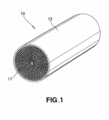
[0023] Figura 1 é uma vista em perspectiva de uma unidade alveolada para controle de emissão de gás de exaustão em uma primeira concretização da presente invenção;[0023] Figure 1 is a perspective view of a honeycomb unit for controlling exhaust gas emission in a first embodiment of the present invention;
[0024] Figura 2 é uma vista em corte transversal diagramática de uma estrutura alveolada da unidade alveolada mostrada na figura 1;[0024] Figure 2 is a diagrammatic cross-sectional view of a honeycomb structure of the honeycomb unit shown in figure 1;
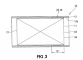
[0025] Figura 3 é umas vista em corte transversal da unidade alveolada com a estrutura alveolada de metal unida a um tubo externo de metal;[0025] Figure 3 is a cross-sectional view of the honeycomb unit with the honeycomb metal structure attached to an external metal tube;
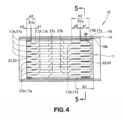
[0026] Figura 4 é uma vista mostrando como uma tira de união é posicionada com relação às porções de união da estrutura alveolada de metal;[0026] Figure 4 is a view showing how a joining strip is positioned in relation to the joining portions of the metal honeycomb structure;
[0027] Figura 5 é uma vista em corte transversal tomada ao longo da linha 5-5 da figura 4;[0027] Figure 5 is a cross-sectional view taken along line 5-5 of figure 4;
[0028] Figura 6A é uma vista em corte transversal diagramática de uma estrutura alveolada de uma unidade alveolada para controle de emissão de gás de exaustão em uma segunda concretização da presente invenção;[0028] Figure 6A is a diagrammatic cross-sectional view of a honeycomb structure of a honeycomb unit for controlling exhaust gas emission in a second embodiment of the present invention;
[0029] Figura 6B é uma vista em corte transversal da unidade alveolada da figura 6A com a estrutura alveolada de metal unida a um tubo externo de metal; e[0029] Figure 6B is a cross-sectional view of the honeycomb unit of figure 6A with the honeycomb metal structure attached to an external metal tube; and
[0030] Figura 7 é uma vista mostrando como uma tira de união é posicionada relativa às porções de união da estrutura alveolada de metal da unidade alveolada na segunda concretização.[0030] Figure 7 is a view showing how a joining strip is positioned relative to the joining portions of the metal honeycomb structure of the honeycomb unit in the second embodiment.
[0031] Com referências às figuras 1 a 5, é mostrada uma unidade alveolada 10 para controle de emissão de gás de exaustão em uma primeira concretização da presente invenção. A unidade alveoladas 10 inclui uma estrutura alveolada de metal 11 em um tubo externo de metal 1 envolve a estrutura alveolada 11.[0031] Referring to figures 1 to 5, a
[0032] Como mostrado nas figuras 1, 4 e 5, a estrutura alveolada de metal 11 inclui uma folha plana de metal 15 e uma folha corrugada de metal 16 colocada na folha plana 15 e enrolada junta de modo espiralado com a folha plana 15. A estrutura alveolada 11 é prensada contra e firmemente unida ao tubo externo 12.[0032] As shown in figures 1, 4 and 5, the honeycomb structure of
[0033] A folha plana 15 e a folha corrugada 16 são unidas juntas pelas primeira e segunda porções de união 17A, 17B da estrutura alveolada 11, como adiante detalhado. A estrutura alveolada 11 é unida ao tubo externo de metal 12 através de uma tira de união 18 como adiante detalhado.[0033] The
[0034] Voltando-se às figuras 2 e 5, a folha plana 15, que provê um núcleo da estrutura alveolada 11, é enrolada de modo espiralado em um eixo central 33 da estrutura alveolada 11. A folha corrugada 16 é enrolada estendendo-se entre voltas adjacentes das folhas planas enroladas 15. A folha corrugada 16 é soldada por brasagem na folha plana 15 pela primeira porção de união 17A disposta proximamente a uma entrada de gás de exaustão 21 da estrutura alveolada 11 e pela segunda porção de união 17B disposta proximamente a uma saída de gás de exaustão 22 da estrutura alveolada 11.[0034] Turning to figures 2 and 5, the
[0035] Mais especificamente, as primeira e segunda porções de junção 17A, 17B são localizadas próximas as extremidades que se opõem 23, 24 da estrutura alveolada 11 e soldam por brasagem a folha plana 15 e a folha corrugada 16 juntas de modo completo. A primeira porção de união 17A inclui primeiras seções de união 17a formadas de materiais de brasagem aplicados às cristas de uma superfície externa 27 da folha corrugada 16 e segundas seções de união17b formadas de materiais de brasagem aplicados às cristas de um superfície interna 28 da folha corrugada 16. A segunda porção de união 17B inclui primeiras seções de união 17c formadas de materiais de brasagem aplicados às cristas da superfície externa 27 da folha corrugada 16 e segundas seções de junção 17d formadas de materiais de brasagem aplicados às cristas da superfície interna 28 da folha corrugada 16.[0035] More specifically, the first and
[0036] As primeiras seções de união 17a são deslocadas das segundas seções de união 17b em direções paralelas ao eixo central 33 da estrutura alveolada 11. As primeiras seções de união 17c são deslocadas das segundas seções de união 17d em direções paralelas ao eixo central 33 da estrutura alveolada 11.[0036] The first joining
[0037] Como mostrado na figura 3, a tira de união 18 é formada de um material de brasagem 25 unida ao tubo externo de metal 12. A tira de união 18 é disposta apenas em um lado da saída de gás de exaustão 22 definida por uma extremidade 34 da estrutura alveolada 11. A tira de união 18 tem uma extensão B1, de uma extremidade 34 a entrada de gás de exaustão 21, ao longo do eixo 33 da estrutura alveolada 11.[0037] As shown in figure 3, the connecting
[0038] Voltando-se à figura 4, a segunda porção de união 17B localizada proximamente à saída de gás de exaustão 22 sobrepõe a tira de união 18. A primeira porção de união 17A é deslocada da tira de união 18 na direção paralela ao eixo 33 (figura 2) da estrutura alveolada 11 sem sobreposição da tira de união 18.[0038] Turning to figure 4, the
[0039] A primeira porção de união 17A possui uma primeira extensão de brasagem A2 – δ1b ao longo do eixo central 33 da estrutura alveolada 11. A primeira extensão de brasagem A2 – δ1b é definida como a soma de uma extensão de brasagem b2 de uma das primeiras seções de união17a e uma extensão de brasagem b1 de uma das segundas seções de união 17b. A segunda porção de união 17B possui uma segunda extensão de brasagem A1 - δ1a ao longo do eixo central 33 da estrutura alveolada 11. A segunda extensão de brasagem A1 - δ1a é definida como a soma de uma extensão de brasagem a1 de uma das primeiras seções de união 17c e uma extensão de brasagem a2 de uma das segundas seções de união 17d.[0039] The first
[0040] O termo "extensão de brasagem" da porção de união significa uma extensão da porção de união que se estende na direção paralela ao eixo 33 da estrutura alveolada 11.[0040] The term "brazing extension" of the connection portion means an extension of the connection portion that extends in the direction parallel to the
[0041] A segunda extensão de brasagem A1 – δ1a da segunda porção de união 17B é maior do que a primeira extensão de brasagem A2 – δ1b da primeira porção de união 17A (isto é., (A2 – δ1b) ˂ (A1 – δ1a)). O δ1a é definido como uma distância pela qual cada uma das primeiras seções de união 17a é deslocada cada qual das segundas seções de união 17b em uma direção paralela ao eixo central 33 da estrutura alveolada 11. Similarmente, o δ1b é definida como uma distância pela qual cada uma das primeiras seções de união 17c é deslocada de cada uma das segundas seções 17d na direção paralela ao eixo central 33 da estrutura alveolada 11. Esta distância indicada em δ1a ou δ1b é a seguir referida como "folga".[0041] The second brazing extension A1 - δ1a of the second joining
[0042] A tira de união 18 localizada em um lado da saída de gás de exaustão 22 possui uma extremidade traseira 18b. As primeiras seções de união 17c localizadas no lado da saída de gás de exaustão 22 têm extremidades traseiras 36. A extremidade traseira 18b da tira de união 28 é localizada para trás das extremidades traseiras 36 das primeiras seções de união 17c.[0042] The connecting
[0043] As primeiras seções de união 17a sobre uma superfície 27a da folha corrugada 16 são dispostas adjacentes às segundas seções de união 17b em uma superfície oposta 27b a folha corrugada16, em direções paralelas ao eixo central 33 da estrutura aoveolada 11. As primeiras seções de união 17c em uma superfície 27a da folha corrugada 16 são dispostas adjacentes às segundas seções de união 17b na superfície oposta 27b da folha corrugada 16, nas direções paralelas ao eixo central 33 da estrutura alveolada 11.[0043] The first joining
[0044] Cada uma das primeiras seções de união 17a é deslocada de cada uma das segundas seções de união 17b pela folga δ1b. Cada uma das primeiras seções de união 17c é deslocada de cada uma das segundas seções de união 17d pela folga δ1a.[0044] Each of the first joining
[0045] A tira de união 18 unida ao tubo externo de metal 12 sobrepõe a segunda porção de união 17B tendo a extensão de brasagem A1 – δ1a maior do que a primeira extensão de brasagem A2 –δ1b da primeira porção de união 17A que não sobrepõe a tira de união 18. A extensão maior da porção de união sobrepondo a tira de união 18 que podia ser submetida a uma forma maior melhora a rigidez da estrutura alveolada 11 para deste modo prevenir a deformação da estrutura alveolada 11.[0045] The connecting
[0046] Uma vez que a tira de união 18 é disposta apenas no lado da saída de gás de exaustão 22, a estrutura alveolada de metal 11 é permitida expandir movendo-se para um lado dianteiro do tubo externo de metal 12 quando a estrutura alveolada 11 aumenta em temperatura. Esta expansão e movimento reduzem uma carga na estrutura alveolada de metal.[0046] Since the connecting
[0047] A extremidade traseira 18b da tira de união 18 localizada para trás das extremidades traseiras 36 das primeiras seções de união 17c fica mais próxima à saída de gás de exaustão 22 do que à entrada 21. O local da extremidade traseira 18b da tira de união 18 é aquela em que uma temperatura pode aumentar menos que qualquer outra parte da estrutura alveolada 11. O local da extremidade traseira 18b localizada para trás das extremidades traseiras 36 das primeiras seções de união previne a deterioração da resistência da união entre a estrutura alveolada de metal 11 e o tubo externo de metal 12, diferente do caso da extremidade traseira 18b ser localizada para frente das extremidades traseiras 36 das primeiras seções de união 17c.[0047] The
[0048] Com a primeira seção de união 17a deslocada da segunda seção de união adjacente 17b pela folga δ1b, a estrutura alveolada 11 pode ser alongada, diferente do caso que a primeira e segunda seções de união adjacentes 17a, 17b sobrepõem. A estrutura alveolada alongada 11 pode ser submetida a uma força menor para deste modo melhorar a durabilidade da unidade alveolada 10.[0048] With the first
[0049] Com referência à figura 6A, é mostrada uma estrutura alveolada de metal 11 em uma segunda concretização, da presente invenção. A estrutura alveolada de metal 11 inclui uma folha plana 15 e uma folha corrugada 16 soldada por brasagem na folha plana 15 através da primeira e segunda porções de união 17A, 17B localizadas próximas a entrada e a saída de exaustão 21, 22 da estrutura alveolada 11. As primeira e segunda porções de união 17A,17B são formadas de materiais de brasagem aplicados às folha corrugada 16, conforme detalhada abaixo.[0049] With reference to figure 6A, a honeycomb structure of
[0050] As primeiras porções de união 17A, 17B são localizadas próxima das extremidades que se opõem da estrutura alveolada 11. A primeira porção de união 17A inclui primeiras seções de união 17a formadas de materiais de brasagem aplicados a uma superfície externa 27 da folha corrugada 16 e segundas seções de união 17b formadas de materiais de brasagem aplicados a uma superfície interna 28 da folha corrugada 16. A segunda porção de união 17B inclui primeiras seções de união 17c formadas de materiais de brasagem aplicados à superfície externa 27 da folha corrugada 16 e as segundas seções de união 17d formadas de materiais de brasagem aplicados à superfície interna 28 da folha corrugada 16.[0050] The first joining
[0051] As primeiras seções de união 17a são deslocadas das segundas seções de união 17b em direções paralelas a um eixo central 33 da estrutura alveolada de metal 11. As primeiras seções de união 17c são deslocadas das segundas seções de união 17d em direções paralelas ao eixo central 33 da estrutura alveolada 11.[0051] The first joining
[0052] Voltando-se à figura 6B, a estrutura alveolada 11 inclui uma tira de união 18 unida a um tubo externo de metal 12. A tira de união 18 é formada de um material de brasagem sobre uma parede interna 12b do tubo externo de metal 12. A tira de união 18 sobrepõe a segunda porção de união 17B em uma direção ortogonal ao eixo central 33 da estrutura alveolada 11. A tira de união 18 possui uma extensão de brasagem B2 maior do que uma extensão de brasagem da porção de união 17B.[0052] Turning to figure 6B, the
[0053] Mais especificamente, como mostrado na figura 7, a tira de união 18 sobrepõe todas as seções de união 17c, 17d da seção de união 17B e possui a extensão da brasagem B2 maior do que a extensão da brasagem A1 – δ1a da porção de união 17B.[0053] More specifically, as shown in figure 7, the connecting
[0054] Quanto a uma estrutura alveolada convencional, as folhas adjacentes plana e corrugadas são unidas nas juntas dispostas na forma de pontos ou em uma forma em ziguezague. A estrutura alveolada é unida a um tubo externo de metal através de uma tira de união. Cada uma das juntas possui uma extensão maior do que uma extensão da tira de união.[0054] As for a conventional honeycomb structure, the adjacent flat and corrugated sheets are joined at the joints arranged in the form of dots or in a zigzag shape. The honeycomb structure is attached to an external metal tube using a joining strip. Each of the joints has an extension greater than an extension of the joining strip.
[0055] Quanto à estrutura alveolada na presente invenção, todavia, a tira de união 18 unida ao tubo externo de metal 12 sobrepõe todas as seções de união 17c, 17d da porção de união 17B e possui a extensão de brasagem B2 maior do que a extensão de brasagem A1 –δ1a da porção de união 17B (A1 – δ11a) ˂ B2). Isto porque a porção de união 17B forma a base da tira de união 18 completamente que a estrutura alveolada de metal 11 possui resistência melhorada para prevenir a deformação da estrutura alveolada 11.[0055] Regarding the honeycomb structure in the present invention, however, the connecting
[0056] Uma vez que a tira de união 18 fica disposta apenas no lado da saída de gás de exaustão 22, a estrutura alveolada de metal 11 é permitida expandir movimentando-se para o lado dianteiro do membro tubular externo de metal 12 quando a estrutura alveolada 11 aumenta em temperatura. Esta expansão e movimento reduzem uma carga na estrutura alveolada de metal 11.[0056] Since the joining
[0057] A tira de união 18 possui uma extremidade traseira 18b localizada para trás das extremidades traseiras 36 das primeiras seções de união 17c e mais próximas à saída de gás de exaustão 22 do que para a entrada 21. Esta localização da extremidade traseira 18b da tira de união 18 é aquela em que uma temperatura pode crescer menos que qualquer outra parte da estrutura alveolada 11. O local da extremidade traseira 18b para trás das extremidades traseiras 36 das primeiras seções de união 17c mantém a resistência da união entre a estrutura alveolada de metal 11 e o tubo externo de metal 12 diferente que no caso da extremidade traseira 18b sendo localizada para frente das extremidades traseiras 36 das primeiras seções de união 17c.[0057] The
[0058] Com a primeira seção de união 17a deslocada da segunda seção de união 17b pela folga δ1a, a estrutura alveolada 11 pode ser alongada, diferente do caso das adjacentes primeira e segunda seções de união 17a, 17b sobrepondo. A estrutura alveolada alongada 11 pode ser submetida à força menor para deste modo melhorar a durabilidade da unidade alveolada 10.[0058] With the
[0059] Exemplos 1 a 4 abaixo mostram dados experimentais corroborando as vantagens providas pela unidade alveolada da presente invenção.[0059] Examples 1 to 4 below show experimental data corroborating the advantages provided by the honeycomb unit of the present invention.
[0060] Uma folha plana foi preparada. Uma folha de aço inoxidável de 40 μm foi usinada para prover uma folha corrugada. Pasta de material de brasagem preparada de um solvente e um aglutinante foi aplicado nos predeterminados pontos sobre cristas da folha corrugada. Então, a folha plana e a folha corrugada são colocadas uma sobre outra e enroladas juntas em um núcleo alveolado de φ40 x L90. O núcleo alveolado foi inserido em e soldado por brasagem em um tubo externo em um forno a vácuo para prover uma unidade alveolada para controle de emissão de gás de exaustão. Deve se notar que o núcleo alveolado foi soldado por brasagem no tubo através de uma tira de união de material de brasagem.[0060] A flat sheet was prepared. A 40 μm stainless steel sheet was machined to provide a corrugated sheet. Paste of brazing material prepared from a solvent and a binder was applied at the predetermined points on ridges of the corrugated sheet. Then, the flat sheet and the corrugated sheet are placed on top of each other and wrapped together in a honeycomb core of φ40 x L90. The honeycomb core was inserted into and brazed by brazing in an external tube in a vacuum oven to provide a honeycomb unit for controlling exhaust gas emissions. It should be noted that the honeycomb core has been soldered by brazing the tube through a joining strip of brazing material.
[0061] O núcleo alveolado tinha porções de união do lado de entrada e saída que soldam por brasagem a folha corrugada na folha plana. A porção de união do lado de entrada ficava 4mm distante de uma extremidade de entrada do núcleo alveolado e a porção de união de saída ficava 4 mm distante de uma extremidade de saída do núcleo alveolado. A tira de união entre o núcleo alveolado e o tubo externo tinha uma extensão de 20mm a contar da extremidade de saída do núcleo alveolado.[0061] The honeycomb core had joining portions on the inlet and outlet side that braze the corrugated sheet on the flat sheet. The coupling portion of the inlet side was 4mm distant from an inlet end of the honeycomb core and the outlet union portion was 4mm distant from an outlet end of the honeycomb core. The joining strip between the honeycomb core and the outer tube was 20mm long from the outlet end of the honeycomb core.
[0062] Cada uma das porções de união do lado de entrada e a porção de união do lado de saída incluíam seções de união externas em um lado externo da folha corrugada e seções de união interna em um lado interno da folha corrugada. As seções de união externa e as seções de união interna foram dispostas em uma forma em ziguezague. O termo "forma em ziguezague " a seguir significa que cada qual das seções de união externa é deslocada por uma folga (2mm no Exemplo 1) de uma adjacente das seções de união interna em uma direção paralela a um eixo central do núcleo alveolado. Deve-se notar que as seções de união no lado externo da folha corrugada foram localizadas no lado da extremidade de saída do núcleo alveolado.[0062] Each of the joining portions of the inlet side and the joining portion of the outgoing side included external joining sections on an outer side of the corrugated sheet and inner joining sections on an inner side of the corrugated sheet. The outer joining sections and the inner joining sections were arranged in a zigzag shape. The term "zigzag shape" below means that each of the outer joining sections is displaced by a clearance (2mm in Example 1) from one adjacent to the inner joining sections in a direction parallel to a central axis of the honeycomb core. It should be noted that the joining sections on the outer side of the corrugated sheet were located on the side of the outlet end of the honeycomb core.
[0063] As amostras da unidade alveolada foram preparadas como mostrado na Tabela 1 abaixo. Estas amostras tinham diferentes extensões de brasagem (b1, b2, a1, a2) das seções de união de cada uma da porção de união do lado de entrada e porção de união do lado de saída. Destas dez amostras, as amostras J-(1) a J-(5) foram feitas de acordo com a presente invenção. As amostras H-(1) a H-(5) foram aquelas comparativas.[0063] Samples from the honeycomb unit were prepared as shown in Table 1 below. These samples had different brazing extensions (b1, b2, a1, a2) of the joining sections of each of the joining portion of the inlet side and joining portion of the outlet side. From these ten samples, samples J- (1) to J- (5) were made according to the present invention. The samples H- (1) to H- (5) were the comparative ones.
[0064] Cada uma das amostras foi testada experimentando as vibrações de 20 G a 60 G em um processo de ciclo de temperatura (1000 a 2000 ciclos de alta e baixa temperaturas de 200ºC a 1000ºC) para avaliação de resistência e deformação de célula da amostra testada. A avaliação da resistência da amostra foi feita com base nas quantidades de fissuras na amostra em comparação com um padrão convencional. A avaliação da deformação de célula da amostra foi feita em comparação com um padrão convencional. Em adição, uma quantidade de material de brasagem usado em cada amostra foi avaliada.Com base na resistência avaliada, na deformação de célula e a quantidade de material de brasagem usada avaliadas, uma avaliação compreensiva da amostra foi feita.

[0065] A tabela 1 mostra o resultado de teste indicando a avaliação da resistência e deformação de célula, a avaliação da quantidade de material de brasagem usada e a avaliação compreensiva de cada amostra.[0065] Table 1 shows the test result indicating the evaluation of cell resistance and deformation, the evaluation of the amount of brazing material used and the comprehensive evaluation of each sample.
[0066] Da Tabela 1, foi constatado que as seções de união da porção de união do lado de saída foram requeridas que tenham uma extensão de brasagem (a1, a2) maior do que 7mm. De preferência, uma extensão de brasagem (a1, a2) é 10mm. Também, em resumo foi constatado que a extensão de brasagem (b1, b2) das seções de união da porção de união do lado de entrada raramente refere-se à resistência. A Tabela 1 indica que a deformação de célula é algo maior quando a extensão de brasagem (b1, b2) é 7mm ou mais. Uma extensão de brasagem mais curta é eficaz em termos de custo porque isto provê uma pequena quantidade de material de brasagem usada. Todavia, com a extensão de brasagem (b1, b2) de 1mm, a avaliação compreensiva era "Não é boa". Isto porque a extensão de brasagem de 1 mm levou a brasagem a parcial falha entre a folha plana e a folha corrugada. Assim, a extensão de brasagem (b1,b2) deverá ser 7mm ou menos, de preferências, 2mm a 5mm.[0066] From Table 1, it was found that the joining sections of the joining portion of the outlet side were required to have a brazing extension (a1, a2) greater than 7mm. Preferably, a brazing extension (a1, a2) is 10mm. Also, in summary, it was found that the brazing extension (b1, b2) of the joining sections of the joining portion of the inlet side rarely refers to the resistance. Table 1 indicates that the cell deformation is somewhat greater when the brazing extension (b1, b2) is 7mm or more. A shorter brazing length is cost effective because it provides a small amount of used brazing material. However, with the brazing extension (b1, b2) of 1mm, the comprehensive assessment was "Not good". This is because the 1 mm brazing extension has caused the brazing to partially fail between the flat sheet and the corrugated sheet. Thus, the brazing extension (b1, b2) should be 7mm or less, preferably 2mm to 5mm.
[0067] Uma folha plana foi preparada. Uma folha de aço inoxidável de 40 μm foi usinada para prover uma folha corrugada. Pasta de material de brasagem preparada de um solvente e um aglutinante foi aplicado nos predeterminados pontos sobre cristas da folha corrugada. Então, a folha plana e a folha corrugada são colocadas uma sobre outra e enroladas juntas em um núcleo alveolado de φ40 x L90. O núcleo alveolado foi inserido em e soldado por brasagem em um tubo externo em um forno a vácuo para prover uma unidade alveolada para controle de emissão de gás de exaustão. Deve se notar que o núcleo alveolado foi soldado por brasagem no tubo externo através de um material de brasagem.[0067] A flat sheet was prepared. A 40 μm stainless steel sheet was machined to provide a corrugated sheet. Paste of brazing material prepared from a solvent and a binder was applied at the predetermined points on ridges of the corrugated sheet. Then, the flat sheet and the corrugated sheet are placed on top of each other and wrapped together in a honeycomb core of φ40 x L90. The honeycomb core was inserted into and brazed by brazing in an external tube in a vacuum oven to provide a honeycomb unit for controlling exhaust gas emissions. It should be noted that the honeycomb core was brazed on the outer tube using a brazing material.
[0068] O núcleo alveolado tinha porções de união do lado de entrada e saída que soldam por brasagem a folha corrugada na folha plana. A porção de união do lado de entrada tinha uma extensão de brasagem de 5mm a contar de um local que era 4mm distante de uma extremidade de entrada do núcleo alveolado e a porção de união do lado de saída tinha uma extensão de brasagem de 10mm a contar de um local que era 4mm distante de uma extremidade de saída do núcleo alveolado.[0068] The honeycomb core had joining portions on the inlet and outlet side that braze the corrugated sheet on the flat sheet. The coupling portion of the inlet side had a 5mm brazing extension from a location that was 4mm distant from an inlet end of the honeycomb core and the coupling portion of the outlet side had a brazing extension of 10mm from from a location that was 4mm away from an outlet end of the honeycomb core.
[0069] Cada uma da porção de união do lado de entrada e a porção de união do lado de saída incluíam seções de união externas em um lado externo da folha corrugada e seções de união interna em um lado interno da folha corrugada. As seções de união externa e as seções de união interna foram dispostas em uma forma em ziguezague com folgas (δ1a, δ1b) de 2mm. Deve-se notar que as seções de união no lado externo da folha corrugada foram localizadas no lado da extremidade de saída do núcleo alveolado.[0069] Each of the joining portion of the inlet side and the joining portion of the outlet side included outer joining sections on an outer side of the corrugated sheet and inner joining sections on an inner side of the corrugated sheet. The outer joining sections and the inner joining sections were arranged in a zigzag shape with clearances (δ1a, δ1b) of 2mm. It should be noted that the joining sections on the outer side of the corrugated sheet were located on the side of the outlet end of the honeycomb core.
[0070] Nove amostras da unidade alveolada foram preparadas como mostrado na Tabela 2 abaixo. Estas nove amostras têm diferentes extensões de brasagem de tiras de união de material de brasagem entre o núcleo alveolado e o tubo externo nos lados de entrada e/ou saída das amostras. O sinal de referência "- " na tabela 2 significa nenhuma extensão de brasagem. Isto é, por exemplo, na amostra J-(6), o núcleo alveolado não foi soldado por brasagem no tubo externo no lado da entrada da amostra. Na amostra H-(7), também, o núcleo alveolado não foi soldado por brasagem no tubo externo no lado da saída da amostra. Destas nove amostras, as amostras J-(6) a J-(9) foram feitas de acordo com a presente invenção. As amostras H-(6) a H-(10) eram aquelas comparativas. A extensão de brasagem (B-1) da tira de união no lado de saída da amostra é definida como uma extensão a partir da extremidade de saída do núcleo alveolado da amostra.[0070] Nine samples from the honeycomb unit were prepared as shown in Table 2 below. These nine samples have different brazing strips of brazing material joining strips between the honeycomb core and the outer tube on the sample inlet and / or outlet sides. The reference sign "-" in table 2 means no brazing extension. That is, for example, in sample J- (6), the honeycomb core was not brazed in the outer tube on the sample inlet side. In sample H- (7), too, the honeycomb core was not brazed in the outer tube on the sample outlet side. From these nine samples, samples J- (6) to J- (9) were made according to the present invention. The samples H- (6) to H- (10) were comparative ones. The brazing extension (B-1) of the joining strip on the sample outlet side is defined as an extension from the outlet end of the sample's honeycomb core.
[0071] Cada uma das amostras foi testada experimentando vibrações de 20 G a 60 G em um processo de ciclo de temperatura (1000 a 2000 mil ciclos de alta e baixa temperaturas de 200º C 1000º C ) para avaliação da resistência e deformação de célula da amostra testada. A avaliação de resistência da amostra foi feita com base nas quantidades de fissuras na amostra em comparação com o padrão convencional. A avaliação da deformação da célula da amostra foi feita em comparação com um padrão convencional. Em adição, uma quantidade de material de brasagem usado em cada amostra foi avaliada. Com base na resistência da avaliação, a deformação de célula e a quantidade de material de brasagem usado em cada amostra foi avaliada. Uma avaliação compreensiva foi feita.

[0072] A tabela 2 mostra o resultado de teste indicando a avaliação da resistência e deformação de célula, a avaliação da quantidade de material de brasagem usada e a avaliação compreensiva de cada amostra.[0072] Table 2 shows the test result indicating the evaluation of cell resistance and deformation, the evaluation of the amount of brazing material used and the comprehensive evaluation of each sample.
[0073] A tabela 2 indica que a amostra H-6 com o núcleo alveolado soldado por brasagem no tubo através das tiras de união em ambos os lados da entrada e saída provê muito pobre resistência uma vez que não é possível que o núcleo alveolado seja alongado para dirigir o esforço térmico em uma direção do alongamento do núcleo. A tabela 2 também indica que a amostra H-(7) com o núcleo alveolado soldado por brasagem no tubo externo através da tira de união apenas no seu lado de entrada provê uma pobre avaliação da deformação de célula uma vez que a deformação de célula é mais grave que o padrão convencional. As amostras J-(6) a J-(9) cada qual tem o núcleo alveolado e o tubo externo soldado por brasagem juntamente através da tira de união disposta apenas no seu lado de saída.[0073] Table 2 indicates that the sample H-6 with the honeycomb core brazed in the tube through the joining strips on both sides of the inlet and outlet provides very poor resistance since it is not possible for the honeycomb core to be stretched to direct the thermal stress in one direction of the core elongation. Table 2 also indicates that the sample H- (7) with the honeycomb core brazed in the outer tube through the joining strip only on its inlet side provides a poor assessment of cell deformation since the cell deformation is more severe than the conventional standard. Samples J- (6) to J- (9) each have the honeycomb core and the outer tube brazed by brazing together through the joining strip disposed only on its outlet side.
[0074] O resultado de teste na tabela 2 mostra que a resistência é melhor quando a extensão de brasagem é 15mm ou mais e é insuficiente quando a extensão da soldagem é 10 mm ou menos. Um estudo da causa da resistência insuficiente mostrada na Tabela 2 revela que a resistência insuficiente resulta do dano concentrado na tira de união quando a extensão da tira de união é igual ou menor do que uma extensão de brasagem de uma porção de união do núcleo alveolado. Assim, a extensão da tira de união entre o núcleo alveolado e o tubo externo necessita que seja maior do que a extensão da posição de união do núcleo alveolado.[0074] The test result in table 2 shows that the resistance is better when the brazing extension is 15mm or more and is insufficient when the welding extension is 10 mm or less. A study of the cause of insufficient strength shown in Table 2 reveals that insufficient strength results from concentrated damage to the joint strip when the length of the joint strip is equal to or less than a brazing extension of a joint portion of the honeycomb core. Thus, the length of the joining strip between the honeycomb core and the outer tube needs to be greater than the length of the joining position of the honeycomb core.
[0075] Uma folha plana foi preparada. Uma folha de aço inoxidável de 40 μm foi usinada para prover uma folha corrugada. Pasta de material de brasagem preparada de um solvente e um aglutinante foi aplicada nos predeterminados pontos sobre cristas da folha corrugada. Então, a folha plana e a folha corrugada são colocadas uma sobre a outra e enroladas juntas em um núcleo alveolado de φ40 x L90. O núcleo alveolado foi inserido em e soldado por brasagem em um tubo externo em um forno a vácuo para prover uma unidade alveolada para controle de emissão de gás de exaustão. Deve se notar que o núcleo alveolado foi soldado por brasagem no tubo através de uma tira de união de material de brasagem.[0075] A flat sheet was prepared. A 40 μm stainless steel sheet was machined to provide a corrugated sheet. Paste of brazing material prepared from a solvent and a binder was applied at the predetermined points on ridges of the corrugated sheet. Then, the flat sheet and the corrugated sheet are placed on top of each other and wrapped together in a núcleo40 x L90 honeycomb core. The honeycomb core was inserted into and brazed by brazing in an external tube in a vacuum oven to provide a honeycomb unit for controlling exhaust gas emissions. It should be noted that the honeycomb core has been soldered by brazing the tube through a joining strip of brazing material.
[0076] O núcleo alveolado tinha porções de união do lado de entrada e saída que soldam por brasagem a folha corrugada na folha plana. A porção de união do lado de entrada tinha uma extensão de brasagem de 5mm a contar de um local que era 4mm distante de uma extremidade de entrada do núcleo alveolado e a porção de união do lado de saída tinha uma extensão de brasagem de 10mm a contar de um local que era 4mm distante de uma extremidade de saída do núcleo alveolado.[0076] The honeycomb core had joining portions on the inlet and outlet side that braze the corrugated sheet on the flat sheet. The coupling portion of the inlet side had a 5mm brazing extension from a location that was 4mm distant from an inlet end of the honeycomb core and the coupling portion of the outlet side had a brazing extension of 10mm from from a location that was 4mm away from an outlet end of the honeycomb core.
[0077] Cada uma da porção de união do lado de entrada e a porção de união do lado de saída incluíam seções de união externas em um lado externo da folha corrugada e seções de união interna em um lado interno da folha corrugada. As seções de união externa e as seções de união interna foram dispostas em uma forma em ziguezague com folgas (δ1a, δ1b) de 2mm. Deve-se notar que as seções de união no lado externo da folha corrugada foram localizadas no lado da extremidade de saída do núcleo alveolado.[0077] Each of the joining side of the inlet side and the joining portion of the outgoing side included outer joining sections on an outer side of the corrugated sheet and inner joining sections on an inner side of the corrugated sheet. The outer joining sections and the inner joining sections were arranged in a zigzag shape with clearances (δ1a, δ1b) of 2mm. It should be noted that the joining sections on the outer side of the corrugated sheet were located on the side of the outlet end of the honeycomb core.
[0078] Seis amostras da unidade alveolada foram preparadas como mostrado na tabela 03 abaixo. As amostras tinham tiras de união de 20 mm de extensão que são localizadas a diferentes distâncias das extremidades de saída das amostras. Destas seis amostras, as amostras J-(10) e J-(11) foram feitas de acordo com a presente invenção e as amostras H-(11) a H-(14) foram exemplos comparativos.[0078] Six samples of the honeycomb unit were prepared as shown in table 03 below. The samples had 20 mm long joining strips that are located at different distances from the sample outlet ends. Of these six samples, samples J- (10) and J- (11) were made according to the present invention and samples H- (11) to H- (14) were comparative examples.
[0079] Cada uma das amostras foram testadas submetendo a vibrações de 20 G a 60 G em um processo de ciclo de temperatura (1000 a 2000 ciclos de alta e baixa temperaturas de 200ºC a 1000ºC) para avaliação de resistência e deformação de célula da amostra testada. Em adição, uma quantidade de material de brasagem usado em cada amostra foi avaliada. Com base na resistência avaliada, na deformação de célula e na quantidade de material de brasagem usado, uma avaliação compreensiva da amostra foi feita.
[0080] Da Tabela 3, foi constatado que a tira de união entre o núcleo alveolado e o tubo externo é de preferência localizado tão próximo da extremidade de saída quanto possível uma vez que é necessário permitir que o esforço térmico no núcleo alveolado seja dirigido na direção de alongamento do núcleo alveolado. A tira de união deverá ser disposta de modo que a extremidade da tira de união não esteja alinhada com a extremidade da tira de união do núcleo alveolado. Isto porque o alinhamento da extremidade da tira de união com a extremidade da porção de união causa a concentração do esforço que conduziria à redução na resistência da unidade alveolada. Assim, a extremidade da tira de união deve ser localizada para trás da extremidade da porção de união. Na presente invenção, a extremidade da tira de união é de 5mm ou menos a contar da extremidade de saída.[0080] From Table 3, it was found that the joining strip between the honeycomb core and the outer tube is preferably located as close to the outlet end as possible since it is necessary to allow the thermal stress on the honeycomb core to be directed at direction of elongation of the honeycomb core. The joining strip should be arranged so that the end of the joining strip is not aligned with the end of the joining strip of the honeycomb core. This is because the alignment of the end of the joining strip with the end of the joining portion causes the concentration of stress that would lead to a reduction in the strength of the honeycomb unit. Thus, the end of the joining strip should be located behind the end of the joining portion. In the present invention, the end of the joining strip is 5 mm or less from the outlet end.
[0081] Uma folha plana foi preparada. Uma folha de aço inoxidável de 40 μm foi usinada para prover uma folha corrugada. Pasta de material de brasagem preparada de um solvente e um aglutinante foi aplicado nos predeterminados pontos sobre cristas da folha corrugada. Então, a folha plana e a folha corrugada são colocadas uma sobre outra e enroladas juntas em um núcleo alveolado de φ40 x L90. O núcleo alveolado foi inserido em e soldado por brasagem em um tubo externo em um forno a vácuo para prover uma unidade alveolada para controle de emissão de gás de exaustão. Deve se notar que o núcleo alveolado foi soldado por brasagem no tubo através de uma tira de união de material de brasagem.[0081] A flat sheet was prepared. A 40 μm stainless steel sheet was machined to provide a corrugated sheet. Paste of brazing material prepared from a solvent and a binder was applied at the predetermined points on ridges of the corrugated sheet. Then, the flat sheet and the corrugated sheet are placed on top of each other and wrapped together in a honeycomb core of φ40 x L90. The honeycomb core was inserted into and brazed by brazing in an external tube in a vacuum oven to provide a honeycomb unit for controlling exhaust gas emissions. It should be noted that the honeycomb core has been soldered by brazing the tube through a joining strip of brazing material.
[0082] O núcleo alveolado tinha porções de união do lado de entrada e saída que soldam por brasagem a folha corrugada na folha plana. A porção de união do lado de entrada tinha uma extensão de brasagem de 5mm a contar de um local que era 4mm distante de uma extremidade de entrada do núcleo alveolado e a porção de união do lado de saída tinha uma extensão de brasagem de 10mm a contar de um local que era 4mm distante de uma extremidade de saída do núcleo alveolado.[0082] The honeycomb core had joining portions on the inlet and outlet side that braze the corrugated sheet on the flat sheet. The coupling portion of the inlet side had a 5mm brazing extension from a location that was 4mm distant from an inlet end of the honeycomb core and the coupling portion of the outlet side had a brazing extension of 10mm from from a location that was 4mm away from an outlet end of the honeycomb core.
[0083] Cada uma da porção de união do lado de entrada e a porção de união do lado de saída incluíam seções de união externas em um lado externo da folha corrugada e seções de união interna em um lado interno da folha corrugada. As seções de união externa e as seções de união interna das respectivas porções de união de entrada e saída foram dispostas em uma forma em ziguezague com folgas (δ1a, δ1b). Deve-se notar que as seções de união no lado externo da folha corrugada foram localizadas no lado da extremidade de saída do núcleo alveolado.[0083] Each of the joining portion of the inlet side and the joining portion of the outlet side included outer joining sections on an outer side of the corrugated sheet and inner joining sections on an inner side of the corrugated sheet. The outer joining sections and the inner joining sections of the respective inlet and outlet union portions were arranged in a zigzag shape with clearances (δ1a, δ1b). It should be noted that the joining sections on the outer side of the corrugated sheet were located on the side of the outlet end of the honeycomb core.
[0084] A tira de união entre o núcleo alveolado e o tubo externo foi localizada apenas no lado da extremidade da saída do núcleo alveolado e tinha uma extensão de 20 mm a contar da extremidade de saída do núcleo alveolado.[0084] The joining strip between the honeycomb core and the outer tube was located only on the outlet end side of the honeycomb core and was 20 mm long from the outlet end of the honeycomb core.
[0085] Oito amostras da unidade alveolada foram preparadas como mostrado na tabela 4 abaixo. Como mostrado na tabela 4 as oito amostras tem diferentes folgas (δ1a, δ1b) com o que as seções de união externa e as seções de união interna foram dispostas na forma em ziguezague. Destas oito amostras, as amostras J-(12) a J-(16) foram feitas de acordo com a presente invenção. As amostras H-(15) a H-(17) foram aquelas comparativas.[0085] Eight samples of the honeycomb unit were prepared as shown in table 4 below. As shown in table 4, the eight samples have different clearances (δ1a, δ1b) with the result that the outer joining sections and the inner joining sections were arranged in a zigzag shape. From these eight samples, samples J- (12) to J- (16) were made according to the present invention. The samples H- (15) to H- (17) were the comparative ones.
[0086] Cada uma das amostras foi testada experimentando as vibrações de 20 G a 60 G em um processo de ciclo de temperatura (1000 a 2000 ciclos de alta e baixa temperaturas de 200ºC a 1000ºC) para avaliação de resistência e deformação de célula da amostra testada. A avaliação da resistência da amostra foi feita com base nas quantidades de fissuras na amostra em comparação com um padrão convencional. A avaliação da deformação de célula da amostra foi feita em comparação com um padrão convencional. Em adição, uma quantidade de material de brasagem usado em cada amostra foi avaliada. Com base na resistência avaliada, na deformação de célula e na quantidade de material de brasagem usado, uma avaliação compreensiva da amostra foi feita.
[0087] Da tabela 4, foi constatado que a resistência era pobre com as seções de união externa sobrepondo às seções de união interna. Isto porque, as fissuras seriam desenvolvidas nas seções de união externa e interna devido ao esforço concentrado na área de sobreposição tendo alta rigidez. Foi também constatado que cada uma das folgas (δ 1a, δ1b) na faixa de 0 a 4 mm provê suficiente resistência. A resistência é baixa quando as folgas (δ1 a, δ1b) são maiores do que 4 mm. Isto porque as folgas maiores mantém esforço térmico de ser direcionado na direção axial do núcleo alveolado quando o núcleo alveolado é alongado na direção axial do núcleo alveolado. A folga ótima era 2 mm. Como resultado, concluiu-se que cada uma das folgas (δ 1a, δ 1b), deveria ser de 0 a 4 mm, de preferência 1 a 3 mm.[0087] From table 4, it was found that the resistance was poor with the outer joining sections overlapping the inner joining sections. This is because, the cracks would be developed in the external and internal joining sections due to the concentrated effort in the overlap area having high rigidity. It was also found that each of the gaps (δ 1a, δ1b) in the range of 0 to 4 mm provides sufficient strength. The resistance is low when the clearances (δ1 to, δ1b) are greater than 4 mm. This is because the larger clearances maintain thermal effort to be directed in the axial direction of the honeycomb core when the honeycomb core is elongated in the axial direction of the honeycomb core. The optimum clearance was 2 mm. As a result, it was concluded that each of the clearances (δ 1a, δ 1b), should be 0 to 4 mm, preferably 1 to 3 mm.
Claims (4)
um tubo externo de metal (12); e
uma estrutura alveolada de metal (11) prensada contra e unida no tubo externo de metal (12);
a estrutura alveolada de metal (11) incluindo:
uma tira de união (18) unida no tubo de metal (12);
uma folha plana (15);
uma folha corrugada (16), colocada na folha plana (15), a folha corrugada (16) e a folha plana (15) sendo enroladas juntas de modo a terem formato cilíndrico, a folha corrugada (16) incluindo uma superfície externa (27) tendo cristas e uma superfície interna (28) tendo cristas;
primeira e segundas porções de união (17A, 17B) soldando por brasagem a folha plana (15) e a folha corrugada (16) juntas; a primeira porção de união (17A) e a segunda porção de união (17B) sendo localizadas próximas as extremidades que se opõem (23, 24) da estrutura alveolada de metal (11);
a primeira porção de união (17A) incluindo primeira seções de união (17a) formadas de material de brasagem aplicadas às cristas da superfície externa (27) da folha corrugada (16) e segundas seções de união (17b) formadas de materiais de brasagem aplicados às cristas de superfície interna (28) da folha corrugada (16);
a segunda porção de união (17B) incluindo primeira seções de união (17c) formadas de material de brasagem aplicados às cristas da superfície externa (27) da folha corrugada (16) e segundas seções de união (17d) formadas de materiais de brasagem aplicados às cristas da superfície interna (28) da folha corrugada (16);
as primeiras seções de união (17a) da primeira porção de união (17A) e as primeiras seções de união (17c) da segunda porção de união (17B) sendo deslocadas das segundas seções de união (17b) da primeira porção de união (17A) e as segundas seções de união (17d) da segunda porção de união (17B) em direções paralelas a um eixo (33) da estrutura alveolada de metal (11);
a segunda porção de união (17B) e a tira de união (18) sobrepondo a primeira porção de união (17A) e a tira de união (18) não sobrepondo;
a primeira porção de união (17A) tendo uma primeira extensão de brasagem ao longo do eixo (33) da estrutura alveolada de metal (11);
a segunda porção de união (17B) tendo uma segunda extensão de brasagem ao longo do eixo (33) da estrutura alveolada de metal (11); e
a segunda extensão de brasagem da segunda porção de união (17B) sendo maior do que a primeira extensão de brasagem da primeira porção de união (17A),
caracterizada pelo fato de que na direção axial da estrutura alveolada (11), folgas (δ1a) tendo um comprimento predeterminado são providas entre as primeiras seções de união (17c) e as segundas seções de união (17d) providas em um lado em que as primeiras seções de união (17c) e as segundas seções de união (17d) sobrepõem a tira de união (18),
todas as folgas (δ1a) são providas dentro de uma largura da tira de união (18) na direção axial da estrutura alveolada (11).Honeycomb unit (10) for controlling exhaust gas emissions, comprising:
an external metal tube (12); and
a honeycomb metal structure (11) pressed against and joined to the outer metal tube (12);
the honeycomb metal structure (11) including:
a joining strip (18) joined to the metal tube (12);
a flat sheet (15);
a corrugated sheet (16), placed on the flat sheet (15), the corrugated sheet (16) and the flat sheet (15) being rolled together to be cylindrical in shape, the corrugated sheet (16) including an outer surface (27 ) having ridges and an inner surface (28) having ridges;
first and second joining portions (17A, 17B) by brazing the flat sheet (15) and the corrugated sheet (16) together; the first coupling portion (17A) and the second coupling portion (17B) being located close to the opposing ends (23, 24) of the metal honeycomb structure (11);
the first joining portion (17A) including first joining sections (17a) formed of brazing material applied to the ridges of the outer surface (27) of the corrugated sheet (16) and second joining sections (17b) formed of applied brazing materials the inner surface ridges (28) of the corrugated sheet (16);
the second joining portion (17B) including first joining sections (17c) formed of brazing material applied to the ridges of the outer surface (27) of the corrugated sheet (16) and second joining sections (17d) formed of applied brazing materials the ridges of the inner surface (28) of the corrugated sheet (16);
the first coupling sections (17a) of the first coupling portion (17A) and the first coupling sections (17c) of the second coupling portion (17B) being displaced from the second coupling sections (17b) of the first coupling portion (17A) ) and the second joining sections (17d) of the second joining portion (17B) in directions parallel to an axis (33) of the metal honeycomb structure (11);
the second splicing portion (17B) and the splicing strip (18) overlapping the first splicing portion (17A) and the splicing strip (18) not overlapping;
the first connecting portion (17A) having a first brazing extension along the axis (33) of the metal honeycomb structure (11);
the second connecting portion (17B) having a second brazing extension along the axis (33) of the metal honeycomb structure (11); and
the second brazing extension of the second joining portion (17B) being greater than the first brazing extension of the first joining portion (17A),
characterized by the fact that in the axial direction of the honeycomb structure (11), clearances (δ1a) having a predetermined length are provided between the first joining sections (17c) and the second joining sections (17d) provided on one side where the first joining sections (17c) and the second joining sections (17d) overlap the joining strip (18),
all clearances (δ1a) are provided within a width of the joining strip (18) in the axial direction of the honeycomb structure (11).
Applications Claiming Priority (2)
| Application Number | Priority Date | Filing Date | Title |
|---|---|---|---|
| JP2011079744A JP5674531B2 (en) | 2011-03-31 | 2011-03-31 | Honeycomb unit for exhaust gas purification |
| JP2011-079744 | 2011-03-31 |
Publications (2)
| Publication Number | Publication Date |
|---|---|
| BR102012007291A2 BR102012007291A2 (en) | 2013-06-04 |
| BR102012007291B1 true BR102012007291B1 (en) | 2021-02-17 |
Family
ID=45929401
Family Applications (1)
| Application Number | Title | Priority Date | Filing Date |
|---|---|---|---|
| BR102012007291-2A BR102012007291B1 (en) | 2011-03-31 | 2012-03-30 | honeycomb unit for exhaust gas emission control |
Country Status (5)
| Country | Link |
|---|---|
| US (1) | US9057311B2 (en) |
| EP (1) | EP2505805B1 (en) |
| JP (1) | JP5674531B2 (en) |
| CN (1) | CN102728741B (en) |
| BR (1) | BR102012007291B1 (en) |
Families Citing this family (6)
| Publication number | Priority date | Publication date | Assignee | Title |
|---|---|---|---|---|
| US20160031027A1 (en) * | 2011-09-05 | 2016-02-04 | Basf Corporation | Method For Applying Brazing Material To Metal Honeycomb Matrix, Metal Honeycomb Matrix And Manufacturing Method Thereof |
| FR3008576B1 (en) | 2013-07-17 | 2016-02-05 | Kuhn Sa | PERFECTED FODDER HARVESTING MACHINE |
| CN104763493B (en) * | 2014-01-08 | 2019-03-05 | 瑞德(新乡)路业有限公司 | A kind of Vehicle Exhaust Particulate trap and filter core |
| CN105705237B (en) * | 2014-02-12 | 2018-01-30 | 新日铁住金高新材料股份有限公司 | Catalyst carrier base material |
| CN107683176A (en) * | 2015-10-06 | 2018-02-09 | 新日铁住金高新材料股份有限公司 | Catalyst load base material and catalyst carrier |
| CN114502824B (en) * | 2019-10-08 | 2024-02-20 | 日铁化学材料株式会社 | Honeycomb unit for purifying exhaust gas and method for producing a honeycomb unit |
Family Cites Families (11)
| Publication number | Priority date | Publication date | Assignee | Title |
|---|---|---|---|---|
| JP2553733B2 (en) * | 1990-04-17 | 1996-11-13 | 昭和飛行機工業株式会社 | Heat resistant structure |
| US5259190A (en) * | 1991-08-01 | 1993-11-09 | Corning Incorporated | Heated cellular structures |
| DE4241469A1 (en) * | 1992-12-09 | 1994-06-16 | Emitec Emissionstechnologie | Catalytic converter with two or more honeycomb bodies in a tubular casing and process for its production |
| DE69416650T2 (en) * | 1993-06-07 | 1999-07-08 | Nippon Yakin Kogyo Co Ltd | EXHAUST GAS PURIFICATION CARRIER AND METHOD FOR PRODUCING THE SAME |
| JP2709789B2 (en) * | 1993-06-07 | 1998-02-04 | 日本冶金工業株式会社 | Exhaust gas purification metal carrier excellent in thermal fatigue resistance and vibration resistance and method for producing the same |
| JPH1076165A (en) * | 1996-09-03 | 1998-03-24 | Usui Internatl Ind Co Ltd | Metallic carrier |
| CN1098970C (en) * | 2000-01-24 | 2003-01-15 | 黄钊仁 | Metal carrier for purifying waste gas and its production process and equipment |
| JP3338703B1 (en) * | 2000-10-10 | 2002-10-28 | 新日本製鐵株式会社 | Method for manufacturing honeycomb body |
| US7410521B2 (en) * | 2005-02-28 | 2008-08-12 | Caterpillar Inc. | Filter service system and method |
| JP4776284B2 (en) * | 2005-06-30 | 2011-09-21 | 本田技研工業株式会社 | Metal carrier structure for exhaust gas purification |
| DE102008016148A1 (en) * | 2008-03-28 | 2009-10-01 | Emitec Gesellschaft Für Emissionstechnologie Mbh | Honeycomb body and method for producing a soldered honeycomb body |
-
2011
- 2011-03-31 JP JP2011079744A patent/JP5674531B2/en active Active
-
2012
- 2012-03-27 EP EP12161374.9A patent/EP2505805B1/en active Active
- 2012-03-30 US US13/435,001 patent/US9057311B2/en active Active
- 2012-03-30 BR BR102012007291-2A patent/BR102012007291B1/en active IP Right Grant
- 2012-03-31 CN CN201210092887.2A patent/CN102728741B/en active Active
Also Published As
| Publication number | Publication date |
|---|---|
| EP2505805B1 (en) | 2016-11-09 |
| BR102012007291A2 (en) | 2013-06-04 |
| JP5674531B2 (en) | 2015-02-25 |
| CN102728741A (en) | 2012-10-17 |
| US20120247076A1 (en) | 2012-10-04 |
| CN102728741B (en) | 2015-01-21 |
| US9057311B2 (en) | 2015-06-16 |
| EP2505805A1 (en) | 2012-10-03 |
| JP2012215085A (en) | 2012-11-08 |
Similar Documents
| Publication | Publication Date | Title |
|---|---|---|
| BR102012007291B1 (en) | honeycomb unit for exhaust gas emission control | |
| US8915292B2 (en) | Exhaust gas heat exchanger and method of operating the same | |
| US20070181294A1 (en) | Exhaust gas heat exchanger and method of operating the same | |
| US9726439B2 (en) | Tube and heat exchanger provided with tube | |
| US20060180299A1 (en) | Flat tube for heat exchanger | |
| WO2008010390A1 (en) | Collecting portion structure of exhaust manifold | |
| KR20120127401A (en) | Heat exchanger for gases, in particular for the exhaust gases of an engine | |
| JP2012097915A (en) | Reinforcing structure of heat exchanger | |
| KR870008656A (en) | Prefabricated clips for soldering | |
| JP4592992B2 (en) | Heat exchanger | |
| JP6577282B2 (en) | Heat exchanger | |
| JP2002228369A (en) | Flat tube for heat exchanger and manufacturing method therefor | |
| JP2005510688A (en) | Tube profile for heat exchanger | |
| JP2007322109A (en) | Integrated type heat exchanger | |
| JP2019095094A (en) | Reinforcement member and reinforcement structure of heat exchanger using the reinforcement member | |
| JP2009198132A (en) | Tube for heat exchanger | |
| US6660401B2 (en) | Disposition of solder for heat resistant structure | |
| JP4121187B2 (en) | EGR gas cooling device | |
| US11774138B2 (en) | Hot water device | |
| JP7386789B2 (en) | heat exchanger core | |
| CN110520685B (en) | Heat exchanger for gases, in particular exhaust gases from an engine, gas circulation tube for an exchanger and method for manufacturing an exchanger | |
| JPH0711332Y2 (en) | Heat exchanger | |
| KR102371237B1 (en) | Water-cooled egr cooler, and the manufacutring method thereof | |
| JP2005300082A (en) | Flat tube for heat exchanger, and manufacturing method of heat exchanger | |
| JP3802206B2 (en) | Inner pipe of double pipe exhaust manifold |
Legal Events
| Date | Code | Title | Description |
|---|---|---|---|
| B03A | Publication of a patent application or of a certificate of addition of invention [chapter 3.1 patent gazette] | ||
| B06F | Objections, documents and/or translations needed after an examination request according [chapter 6.6 patent gazette] | ||
| B06U | Preliminary requirement: requests with searches performed by other patent offices: procedure suspended [chapter 6.21 patent gazette] | ||
| B09A | Decision: intention to grant [chapter 9.1 patent gazette] | ||
| B16A | Patent or certificate of addition of invention granted [chapter 16.1 patent gazette] |
Free format text: PRAZO DE VALIDADE: 20 (VINTE) ANOS CONTADOS A PARTIR DE 30/03/2012, OBSERVADAS AS CONDICOES LEGAIS. |