JP2019095094A - Reinforcement member and reinforcement structure of heat exchanger using the reinforcement member - Google Patents
Reinforcement member and reinforcement structure of heat exchanger using the reinforcement member Download PDFInfo
- Publication number
- JP2019095094A JP2019095094A JP2017222711A JP2017222711A JP2019095094A JP 2019095094 A JP2019095094 A JP 2019095094A JP 2017222711 A JP2017222711 A JP 2017222711A JP 2017222711 A JP2017222711 A JP 2017222711A JP 2019095094 A JP2019095094 A JP 2019095094A
- Authority
- JP
- Japan
- Prior art keywords
- reinforcing member
- main body
- opening
- reinforcement
- reinforcement member
- Prior art date
- Legal status (The legal status is an assumption and is not a legal conclusion. Google has not performed a legal analysis and makes no representation as to the accuracy of the status listed.)
- Granted
Links
Images


Classifications
-
- F—MECHANICAL ENGINEERING; LIGHTING; HEATING; WEAPONS; BLASTING
- F28—HEAT EXCHANGE IN GENERAL
- F28D—HEAT-EXCHANGE APPARATUS, NOT PROVIDED FOR IN ANOTHER SUBCLASS, IN WHICH THE HEAT-EXCHANGE MEDIA DO NOT COME INTO DIRECT CONTACT
- F28D1/00—Heat-exchange apparatus having stationary conduit assemblies for one heat-exchange medium only, the media being in contact with different sides of the conduit wall, in which the other heat-exchange medium is a large body of fluid, e.g. domestic or motor car radiators
- F28D1/02—Heat-exchange apparatus having stationary conduit assemblies for one heat-exchange medium only, the media being in contact with different sides of the conduit wall, in which the other heat-exchange medium is a large body of fluid, e.g. domestic or motor car radiators with heat-exchange conduits immersed in the body of fluid
- F28D1/04—Heat-exchange apparatus having stationary conduit assemblies for one heat-exchange medium only, the media being in contact with different sides of the conduit wall, in which the other heat-exchange medium is a large body of fluid, e.g. domestic or motor car radiators with heat-exchange conduits immersed in the body of fluid with tubular conduits
- F28D1/053—Heat-exchange apparatus having stationary conduit assemblies for one heat-exchange medium only, the media being in contact with different sides of the conduit wall, in which the other heat-exchange medium is a large body of fluid, e.g. domestic or motor car radiators with heat-exchange conduits immersed in the body of fluid with tubular conduits the conduits being straight
-
- F—MECHANICAL ENGINEERING; LIGHTING; HEATING; WEAPONS; BLASTING
- F28—HEAT EXCHANGE IN GENERAL
- F28F—DETAILS OF HEAT-EXCHANGE AND HEAT-TRANSFER APPARATUS, OF GENERAL APPLICATION
- F28F9/00—Casings; Header boxes; Auxiliary supports for elements; Auxiliary members within casings
- F28F9/007—Auxiliary supports for elements
- F28F9/013—Auxiliary supports for elements for tubes or tube-assemblies
-
- F—MECHANICAL ENGINEERING; LIGHTING; HEATING; WEAPONS; BLASTING
- F28—HEAT EXCHANGE IN GENERAL
- F28F—DETAILS OF HEAT-EXCHANGE AND HEAT-TRANSFER APPARATUS, OF GENERAL APPLICATION
- F28F9/00—Casings; Header boxes; Auxiliary supports for elements; Auxiliary members within casings
- F28F9/02—Header boxes; End plates
- F28F9/04—Arrangements for sealing elements into header boxes or end plates
Abstract
Description
乗り物のエンジン冷却水を冷却するための熱交換器(ラジエータ)を補強する構造に関する。 The present invention relates to a structure for reinforcing a heat exchanger (radiator) for cooling vehicle engine cooling water.
エンジン冷却水を冷却するための熱交換器は、例えば一列に並列された多数の偏平チューブと、各偏平チューブの間に配置されるフィンと、各偏平チューブの両端が挿通され、その挿通部がロウ付けされた一対のヘッダープレートと、を備えている。エンジン冷却水は、各偏平チューブ内を通過する際にフィン等による放熱効果によって冷却される。 The heat exchanger for cooling the engine cooling water includes, for example, a plurality of flat tubes arranged in a row, fins disposed between the flat tubes, and both ends of each flat tube, and the insertion portion And a pair of brazed header plates. The engine cooling water is cooled by the heat radiation effect of the fins or the like when passing through the inside of each flat tube.
このような構造の熱交換器は、偏平チューブとヘッダープレートの挿通部とのロウ付け部分に熱歪みの影響で亀裂が生じる場合がある。特に、寒冷地等では、エンジン始動時やエンジン負荷変動時等の過渡的に、外気温と偏平チューブ内を流れる冷却水と(温水)の温度差によって大きな熱歪みが生じやすい。 In the heat exchanger having such a structure, a crack may occur in the brazed portion between the flat tube and the insertion portion of the header plate due to the influence of thermal strain. In particular, in a cold area or the like, large thermal distortion is likely to occur due to the temperature difference between the outside air temperature and the cooling water flowing in the flat tube transiently at the time of engine start or engine load fluctuation.
そこで、例えば、偏平チューブの開口部内に補強部材を挿入して、熱歪みの生じやすい部位を補強することが提案されている(特許文献1参照)。 Therefore, for example, it has been proposed to insert a reinforcing member into the opening of a flat tube to reinforce a portion where thermal strain is likely to occur (see Patent Document 1).
しかしながら、特許文献1の補強構造は、補強部材の端部の断面が半円形に形成されており、この補強部材の半円形の端部が偏平チューブの開口部の半円状の内面部に対して隙間なく接触する構成である。このような構成では、補強部材の製造上の寸法誤差が許容される余地が小さくなり、作業者が補強部材を開口部に挿入する際の作業性を低下させてしまう。また、補強部材が寸法誤差を含む場合、補強部材と偏平チューブの開口部との間にロウ付け後も隙間が生じてしまい、十分な補強の強度が得られない懸念もある。 However, in the reinforcing structure of Patent Document 1, the cross section of the end portion of the reinforcing member is formed in a semicircular shape, and the semicircular end portion of the reinforcing member is against the semicircular inner surface portion of the opening of the flat tube. Contact without gaps. In such a configuration, the room for allowing dimensional error in manufacturing of the reinforcing member becomes small, and the workability when the worker inserts the reinforcing member into the opening decreases. In addition, when the reinforcing member includes a dimensional error, a gap may be generated between the reinforcing member and the opening of the flat tube even after brazing, and there is a concern that a sufficient reinforcing strength can not be obtained.
そこで、本発明の目的は、補強部材の製造上の寸法誤差が作業性に与える影響を低減させつつ、補強部材による補強の強度を安定的に得ることが可能な補強部材および当該補強部材を用いた熱交換器の補強構造を提供することである。 Therefore, an object of the present invention is to use a reinforcing member capable of stably obtaining the strength of reinforcement by the reinforcing member and reducing the influence of dimensional error in manufacturing of the reinforcing member on workability. To provide a heat exchanger reinforcement structure.
本発明の一態様に係る熱交換器の補強構造は、
偏平チューブが挿通される挿通部を有するエンドプレートと、前記挿通部に挿通された前記偏平チューブの開口部に嵌め込まれた状態でロウ付けされる補強部材と、を備える熱交換器の補強構造であって、
前記開口部は、
一対の対向する平行な平面部と、
前記各平面部の両縁間を接続する半円弧状内面部と、
を有し、
前記補強部材は、
長尺状の本体部と、
前記本体部の長手方向の端部に形成される重合部であって、展開状態で平面L字状部であるとともに、そのL字状部の前記長手方向の先端部が、前記本体部側に折り返され且つ重ね合わされて形成される重合部と、
を有し、
前記本体部は、前記補強部材が長手方向に弾性変形することを補助するためのビート部が形成されており、
前記重合部の表面には、ロウ材が付着しており、
前記重合部において折り返された部位の先端は尖っており、前記補強部材が前記開口部に嵌め込まれた状態において、前記先端が前記半円弧状内面部に当接した状態でロウ付けがされている。
The heat exchanger reinforcing structure according to one aspect of the present invention is
A heat exchanger reinforcing structure comprising: an end plate having an insertion portion through which the flat tube is inserted; and a reinforcing member brazed in a state of being inserted into the opening of the flat tube inserted into the insertion portion. There,
The opening is
A pair of opposing parallel flats,
A semicircular arc inner surface connecting the two edges of the flat surface;
Have
The reinforcing member is
A long main body,
The overlapping portion formed at the end of the main body in the longitudinal direction, which is a flat L-shaped portion in the unfolded state, and the distal end of the L-shaped portion in the longitudinal direction is on the main body side An overlapping portion formed by folding back and overlapping;
Have
The main body portion is provided with a beat portion for assisting the elastic member to be elastically deformed in the longitudinal direction,
A brazing material adheres to the surface of the polymerization portion,
The tip of the portion folded back at the overlapping portion is sharp, and in a state where the reinforcing member is fitted into the opening, brazing is performed in a state where the tip is in contact with the semicircular inner surface. .
また、本発明の一態様に係る補強部材は、
長尺状の本体部と、
前記本体部の長手方向の端部に形成される重合部であって、展開状態で平面L字状部であるとともに、そのL字状部の前記長手方向の先端部が、前記本体部側に折り返され且つ重ね合わされて形成される重合部と、
を備える補強部材であって、
前記本体部は、前記補強部材が長手方向に弾性変形することを補助するためのビート部が形成されており、
前記重合部の表面には、ロウ材が付着しており、
前記重合部において折り返された部位の先端は尖っており、前記補強部材が偏平チューブの開口部に嵌め込まれた状態において、前記先端が前記開口部の半円弧状内面部に当接可能である。
In addition, a reinforcing member according to one aspect of the present invention is
A long main body,
The overlapping portion formed at the end of the main body in the longitudinal direction, which is a flat L-shaped portion in the unfolded state, and the distal end of the L-shaped portion in the longitudinal direction is on the main body side An overlapping portion formed by folding back and overlapping;
A reinforcing member comprising
The main body portion is provided with a beat portion for assisting the elastic member to be elastically deformed in the longitudinal direction,
A brazing material adheres to the surface of the polymerization portion,
The tip of the portion folded back at the overlapping portion is sharp, and the tip can contact the semicircular inner surface of the opening in a state where the reinforcing member is fitted into the opening of the flat tube.
上記構成によれば、作業者は、補強部材を長手方向に縮めた状態で開口部に挿入し、補強部材の重合部が開口部に挿入された後に手を放して弾性変形を解放することで、補強部材を開口部に嵌め込むことができる。このように、補強部材を弾性変形可能にすることで、補強部材の寸法誤差が、補強部材を開口部に挿入する際の作業性に与える影響を低減させることができる。また、補強部材の重合部の先端が開口部の半円弧状内面部に当接した状態で加熱がなされると、重合部と半円弧状内面部との当接部位を中心として、ロウ材がその当接部位の周囲(隙間)にも回り込み、補強部材と偏平チューブとがロウ付けされる。このため、補強部材と偏平チューブとが隙間なくロウ付けされやすくなり、補強部材による補強の強度を安定的に得ることができる。 According to the above configuration, the worker inserts the reinforcement member in the longitudinal direction in the state of being contracted, into the opening, and releases the elastic deformation after releasing the hand after the overlapping portion of the reinforcement member is inserted into the opening. The reinforcement member can be fitted into the opening. Thus, by making the reinforcing member elastically deformable, it is possible to reduce the influence of the dimensional error of the reinforcing member on the workability when inserting the reinforcing member into the opening. In addition, when heating is performed with the front end of the overlapping portion of the reinforcing member in contact with the semicircular arc inner surface of the opening, the brazing material is centered on the contact portion between the overlapping portion and the semicircular arc inner surface. The reinforcing member and the flat tube are brazed around the contact portion (gap). Therefore, the reinforcing member and the flat tube are easily brazed without a gap, and the strength of reinforcement by the reinforcing member can be stably obtained.
本発明によれば、補強部材の製造上の寸法誤差が作業性に与える影響を低減させつつ、補強部材による補強の強度を安定的に得ることが可能な補強部材および当該補強部材を用いた熱交換器の補強構造を提供することができる。 According to the present invention, it is possible to stably obtain the strength of reinforcement by the reinforcing member while reducing the influence of the dimensional error in manufacturing of the reinforcing member on the workability, and the heat using the reinforcing member It is possible to provide a reinforcing structure of the exchanger.
以下、図面を参照して本発明の実施の形態に係る熱交換器の補強構造について詳細に説明する。 Hereinafter, the reinforcing structure of the heat exchanger according to the embodiment of the present invention will be described in detail with reference to the drawings.
また、本実施形態の説明では、説明の便宜上、「左右方向」、「前後方向」、「上下方向」について適宜言及する。これらの方向は、図1に示す熱交換器1、図2に示すエンドプレート4、図3〜4に示す補強部材7、図6に示すエンドプレート4Aについて設定された相対的な方向である。ここで、「上下方向」は、「上方向」及び「下方向」を含む方向である。「前後方向」は、「前方向」及び「後方向」を含む方向である。「左右方向」は、「左方向」及び「右方向」を含む方向である。
Further, in the description of the present embodiment, for convenience of description, “left and right direction”, “front and back direction”, and “upper and lower direction” will be referred to as appropriate. These directions are relative directions set for the heat exchanger 1 shown in FIG. 1, the
<第一実施形態>
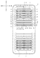
以下、本実施形態の一例を、エンジン冷却水冷却用の熱交換器、いわゆる自動車用ラジエータを用いて説明する。図1は、第一実施形態に係る熱交換器1の補強構造の斜視図である。図2は、補強部材7が取り付けられた状態におけるエンドプレート4の平面図である。図1に示すように、熱交換器1は、偏平チューブ2と、フィン3と、エンドプレート4と、サポート材5と、タンク6と、補強部材7と、を有している。また、熱交換器1には、多数の偏平チューブ2とフィン3とが上下方向に交互に配列されている。フィン3は、例えば、放熱フィンである。
First Embodiment
Hereinafter, an example of the present embodiment will be described using a heat exchanger for cooling engine cooling water, that is, a so-called vehicle radiator. FIG. 1 is a perspective view of the reinforcing structure of the heat exchanger 1 according to the first embodiment. FIG. 2 is a plan view of the
図2に示すように、各偏平チューブ2は、二つの開口部18を有する。開口部18は、長軸と短軸とを有している。開口部18の短軸の長さA(対向する平面部2a間距離)は、開口部18の長軸の長さBの略1/8である。二つの開口部18の間であって、偏平チューブ2の略中央部には柱状部17が形成されている。柱状部17は略直方体である。
As shown in FIG. 2, each
偏平チューブ2の前方に位置する開口部18は、一対の対向する平行な平面部2aと、半円弧状内面部2bと、柱状部の内壁面2cと、で構成されている。半円弧状内面部2bは、その各平面部2aの前方側の両縁間をそれぞれ連結するように形成されており、当該連結点を結ぶ線は半円弧状である。また、内壁面2cは、前後方向において、半円弧状内面部2bと対になる位置に配置されている。内壁面2cは、その各平面部2aの後方側の両縁間をそれぞれ連結するように形成されており、当該連結点を結ぶ線は、直線形状である。
An
偏平チューブ2の後方に位置する開口部18は、一対の対向する平行な平面部2aと、半円弧状内面部2bと、柱状部の内壁面2cと、で構成されている。半円弧状内面部2bは、その各平面部2aの後方側の両縁間をそれぞれ連結するように形成されており、当該連結点を結ぶ線は半円弧状である。また、内壁面2cは、前後方向において、半円弧状内面部2bと対になる位置に配置されている。内壁面2cは、その各平面部2aの前方側の両縁間をそれぞれ連結するように形成されており、当該連結点を結ぶ線は、直線形状である。
An
図1に戻って説明する。最も上部に位置する偏平チューブ2の上方と、最も下部に位置する偏平チューブ2の下方には、サポート材5が配置されている。また、サポート材5の両端はエンドプレート4に固定される。
Referring back to FIG. A
エンドプレート4は角丸形状の略長方形である。エンドプレート4には、上下方向に複数のチューブ挿通孔(挿通部)8が形成されている。チューブ挿通孔8は略長方形であり、チューブ挿通孔8の長軸は、エンドプレート4の短辺よりも短い。チューブ挿通孔8の短辺のうち、エンドプレート4の外周に近い方の短辺の隅は、角丸形状である(図2参照)。エンドプレート4の挿通部8には、偏平チューブ2が挿通されている。
The
タンク6は、タンク本体部9と、を有している。また、右側のタンク6のタンク本体部9の上部には、サポート材5に対して垂直であって、後方向に延びる筒形状の入口パイプ12が設けられている。また、左側のタンク6のタンク本体部9の下部には、サポート材5に対して垂直であって、後方向に延びる筒形状の出口パイプ13が設けられている。タンク本体部9は略直方体である。また、タンク本体部9は小フランジ部10を有している。
The
補強部材7は、少なくとも、エンドプレート4の上下端の開口部18に嵌め込まれている。これら以外の開口部18にも、補強部材7を嵌め込むことは可能だが、全ての開口部18には、補強部材7を嵌め込まないことが好ましい。
The reinforcing
本実施形態では、補強部材7は、エンドプレート4の上側四本の偏平チューブ2の開口部18の各々に、左右方向に二個ずつ挿入されている。また、補強部材7は、エンドプレート4の下側四本の偏平チューブ2の開口部18の各々に、左右方向に二個ずつ挿入されている(図2参照)。
In the present embodiment, two reinforcing
熱交換器1は、互いに接触する各部品の少なくとも一方側にロウ材が被覆又は配置されており、全体を高温の炉内に挿入して、一体的にロウ付けして固定するものである。本実施形態では、タンク6の小フランジ部10が図示しないOリングを介して、エンドプレート4の環状溝15に嵌着され、かしめ用爪部16をかしめることによって、熱交換器1が完成する。
The heat exchanger 1 has a brazing material coated or disposed on at least one side of the parts in contact with each other, and the whole is inserted into a high temperature furnace and integrally brazed and fixed. In the present embodiment, the
高温の冷却水14は、入口パイプ12から右側のタンク6に流通し、各偏平チューブ2内を右から左に流通する。左側のタンク6に到達した冷却水14は、出口パイプ13から流出する。偏平チューブ2およびフィン3の外面にはファンまたは走行風による空気流が流通し、偏平チューブ2内を通過している冷却水14と空気流との間で熱交換が行われる。
なお、本実施形態では、図1で示した左右方向に沿って冷却水が偏平チューブ内を流れる例を説明しているが、この例に限られない。冷却水が流れる方向、つまり、偏平チューブの長手方向が図1の上下方向や前後方向に沿うように、偏平チューブを配置する構成であっても良い。また、偏平チューブは斜めに配置されていても良い。
The high
In the present embodiment, although the example in which the cooling water flows in the flat tube along the left-right direction shown in FIG. 1 is described, the present invention is not limited to this example. The flat tube may be arranged such that the direction in which the cooling water flows, that is, the longitudinal direction of the flat tube is along the vertical direction or the front-rear direction of FIG. 1. Also, the flat tubes may be arranged obliquely.
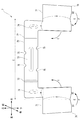
図3は、補強部材7の展開平面図である。図3に示すように、補強部材7は、左右方向に長い長尺状の本体部70と、本体部70の左右方向(長手方向)の端部に形成されるL字状部71を有している。補強部材7は、偏平チューブ2の開口部18に対向する平面部2a間の距離の1/2よりも僅かに小さい板厚の金属板である。その金属板の両面には、ロウ材がコーティングされている。また、補強部材7の左右方向に延びる長さCは、開口部18の長軸の長さと略同一である。
FIG. 3 is a developed plan view of the reinforcing
本体部70には、上下方向(短手方向)に延びるビート72が二つ形成されている。このため、補強部材7は左右方向(長手方向)に弾性変形しやすくなっている。また、本体部70の略中央部には、左右方向に延びるビート73が形成されており、本体部70の中央部分の剛性を補強している。さらに、左側のビート72より左の部位と、右側のビート72より右の部位には、それぞれビート74が形成されており、本体部70の端部の剛性を補強している。
In the
本体部70の長辺略中央部には、半円形状の孔75が各長辺上に二つずつ設けられている。
Two
L字状部71は、展開状態で平面L字状である。また、L字状部71は、折り返し線lを軸に折り返し可能である。すなわち、L字状部71は、左右方向に折り返し可能である。尚、L字状部71の表面には、ロウ材が付着している。
The L-shaped
本体部70の長辺と平行であって、本体部70の長辺から最も離れた位置にあるL字状部71の辺は、その辺上の点D1及びD2から、L字状部71の略中央部であって、点D1と点D2の中間点である点Eに向かって、本体部70方向に屈折している。
The side of the L-shaped
図4は、L字状部71が折り返された状態における補強部材7の平面図である。図4に示す補強部材7は、次のように形成される。
FIG. 4 is a plan view of the reinforcing
まず、図3に示す補強部材7において、L字状部71の先端部76が、矢印F(図3参照)方向に折り返される。その結果、重合部77(図4参照)が形成される。次に、重合部77は、矢印G(図3参照)方向に折り曲げられる。こうして、図4に示す補強部材7は形成される。
First, in the reinforcing
重合部77は、先端部76が矢印F方向に折り返された後、所定の金型等を用いて、折り返された部位の先端(点E)が尖るようにプレス加工される。プレス加工された結果、重合部77の折り返し端縁の横断面は、頂角が略120度の二等辺三角形となる。その後、各重合部77は、折り返し線mを軸として本体部70側に、断面L字状に曲折される。その先端71aは、偏平チューブ2の開口部18に挿入される部位の挿入開始端である。
After the
作業者が本体部70の両端を左右方向に指で軽く押圧すると、補強部材7は、左右方向に僅かに縮むように弾性変形する。こうして縮められた補強部材7の点E間の距離は、偏平チューブ2の開口部18よりも僅かに小さくなるため、作業者は、各重合部77を偏平チューブ2の開口部18に挿入することができる。挿入後、作業者が本体部70への押圧を止めると、補強部材7の弾性変形は解放される。このため、重合部77の先端(点E)の一方は半円弧状内面部2bと当接し、もう一方は、柱状部17の内壁面2cと当接する。
When the worker lightly presses both ends of the
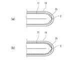
図5の(a)は、偏平チューブと補強部材とをロウ付けする前の偏平チューブを示す図である。図5の(b)は、偏平チューブと補強部材とをロウ付けした後の偏平チューブを示す図である。 (A) of FIG. 5 is a figure which shows the flat tube before brazing with a flat tube and a reinforcement member. (B) of FIG. 5 is a figure which shows the flat tube after brazing a flat tube and a reinforcement member.
各重合部77を偏平チューブ2の開口部18に挿入し、作業者が本体部70への押圧を止めると、図5の(a)に示すように、重合部77の先端(点E)は偏平チューブ2の開口部18の半円弧状内面部2bと当接(正面視で点接触)する。また、ロウ付けのための加熱前において、この当接部位(点E)の周辺には隙間が形成されている。
尚、図5の(a)は、偏平チューブ2の右端部を図示しているが、偏平チューブ2の左端部における点Eも、右端部同様、偏平チューブ2の開口部18の半円弧状内面部2bと当接(正面視で点接触)している。
When each overlapping
5A shows the right end portion of the
図5の(a)の状態から加熱をし、偏平チューブ2と補強部材7との間をロウ付けすると、図5の(b)の示すように、当接部位(点E)を中心として、ロウ材が当接部位の周囲にも回り込む。このため、偏平チューブ2と重合部77とが隙間なくロウ付けされるとともに、偏平チューブ2とエンドプレート4(図1参照)との当接部位もロウ付けされ、より強固な補強構造となる。
When heating is performed from the state of (a) of FIG. 5 and brazing between the
ところで、特許文献1の補強構造は、補強部材の端部の断面が半円形に形成されており、この補強部材の半円形の端部が偏平チューブの開口部の半円状の内面部に対して隙間なく接触する構成である。このような構成では、補強部材の製造上の寸法誤差が許容される余地が小さくなり、作業者が補強部材を開口部に挿入する際の作業性を低下させてしまう。また、補強部材が寸法誤差を含む場合、補強部材と偏平チューブの開口部との間にロウ付け後も隙間が生じてしまい、十分な補強の強度が得られない懸念もある。 By the way, in the reinforcing structure of Patent Document 1, the cross section of the end portion of the reinforcing member is formed in a semicircular shape, and the semicircular end portion of this reinforcing member is against the semicircular inner surface portion of the opening of the flat tube. Contact without gaps. In such a configuration, the room for allowing dimensional error in manufacturing of the reinforcing member becomes small, and the workability when the worker inserts the reinforcing member into the opening decreases. In addition, when the reinforcing member includes a dimensional error, a gap may be generated between the reinforcing member and the opening of the flat tube even after brazing, and there is a concern that a sufficient reinforcing strength can not be obtained.
本実施形態の構成によれば、作業者は、補強部材7を左右方向(長手方向)に縮めた状態で開口部18に挿入し、補強部材7の重合部77が開口部18に挿入された後に手を放して弾性変形を解放することで、補強部材7を開口部18に嵌め込むことができる。このように、補強部材7を弾性変形可能にすることで、補強部材7の寸法誤差が、補強部材7を開口部18に挿入する際の作業性に与える影響を低減させることができる。また、補強部材7の重合部77の先端(点E)が開口部18の半円弧状内面部2bに当接した状態で加熱がなされると、重合部77と半円弧状内面部2bとの当接部位を中心として、ロウ材がその当接部位(点E)の周囲(隙間)にも回り込み、補強部材7と偏平チューブ2とがロウ付けされる。このため、補強部材7と偏平チューブ2とが隙間なくロウ付けされやすくなり、補強部材7による補強の強度を安定的に得ることができる。
According to the configuration of the present embodiment, the worker inserts the reinforcing
<第二実施形態>
図6は、第二実施形態に係る補強部材7Aを取り付けた状態におけるエンドプレート4Aの平面図である。図6に示す補強部材7Aの長さC1は、第一実施形態における補強部材7の長さCに対して、二倍程度である。補強部材7Aに係る重合部77の各先端は、いずれも柱状部17に当接しない。このため、補強部材7Aを取り付けた状態におけるエンドプレート4Aでは、補強部材7Aの重合部77の各先端が、ともに偏平チューブ2の開口部18の半円弧状内面部2bと当接している。この点において、補強部材7Aを取り付けた状態におけるエンドプレート4Aは、第一実施形態に係る補強部材7を取り付けた状態におけるエンドプレート4と異なっている。換言すると、補強部材7Aでは、これが挿入される偏平チューブ2に対応する一対の開口部18にそれぞれ形成される半円弧状内面部2bと、補強部材7Aの重合部77に形成される先端(点E)とが当接している点で、第一実施形態に係る補強部材7を取り付けた状態におけるエンドプレート4とは異なっている。
また、第二実施形態は、補強部材7Aが、エンドプレート4Aの最上位と最下位に位置する偏平チューブ2にのみ挿入されている点においても、第一実施形態と異なっている。
Second Embodiment
FIG. 6 is a plan view of the
The second embodiment is also different from the first embodiment in that the reinforcing
第二実施形態によれば、第一実施形態と比べ、補強部材7Aの数が少なくて済む。また、補強部材7Aの数が少なくて済むので、熱交換器の組立がより容易になる。
According to the second embodiment, the number of reinforcing
なお、本発明は、上述した実施形態に限定されず、適宜、変形、改良等が自在である。その他、上述した実施形態における各構成要素の材質、形状、寸法、数値、形態、数、配置場所等は、本発明を達成できるものであれば任意であり、限定されない。 The present invention is not limited to the above-described embodiment, and appropriate modifications, improvements, and the like can be made. In addition, the materials, shapes, dimensions, numerical values, forms, numbers, arrangement places and the like of each component in the above-described embodiment are arbitrary and not limited as long as the present invention can be achieved.
1:熱交換器、2:偏平チューブ、3:フィン、4:エンドプレート、5:サポート材、6:タンク、7:補強部材、8:チューブ挿通孔(挿通部)、9:タンク本体部、10:小フランジ部、12:入口パイプ、13:出口パイプ、14:冷却水、15:環状溝、16:かしめ用爪部、17:柱状部、18:開口部、71:L字状部、77:重合部 1: Heat exchanger 2: Flat tube 3: Fin 4: End plate 5: Support material 6: Tank 7: Reinforcement member 8: Tube insertion hole (insertion portion) 9: Tank body portion 10: small flange portion, 12: inlet pipe, 13: outlet pipe, 14: cooling water, 15: annular groove, 16: caulking claw portion, 17: columnar portion, 18: opening portion, 71: L-shaped portion, 77: Overlap part
Claims (2)
前記開口部は、
一対の対向する平行な平面部と、
前記各平面部の両縁間を接続する半円弧状内面部と、
を有し、
前記補強部材は、
長尺状の本体部と、
前記本体部の長手方向の端部に形成される重合部であって、展開状態で平面L字状部であるとともに、そのL字状部の前記長手方向の先端部が、前記本体部側に折り返され且つ重ね合わされて形成される重合部と、
を有し、
前記本体部は、前記補強部材が長手方向に弾性変形することを補助するためのビート部が形成されており、
前記重合部の表面には、ロウ材が付着しており、
前記重合部において折り返された部位の先端は尖っており、前記補強部材が前記開口部に嵌め込まれた状態において、前記先端が前記半円弧状内面部に当接した状態でロウ付けがされている、
熱交換器の補強構造。 A heat exchanger reinforcing structure comprising: an end plate having an insertion portion through which the flat tube is inserted; and a reinforcing member brazed in a state of being inserted into the opening of the flat tube inserted into the insertion portion. There,
The opening is
A pair of opposing parallel flats,
A semicircular arc inner surface connecting the two edges of the flat surface;
Have
The reinforcing member is
A long main body,
The overlapping portion formed at the end of the main body in the longitudinal direction, which is a flat L-shaped portion in the unfolded state, and the distal end of the L-shaped portion in the longitudinal direction is on the main body side An overlapping portion formed by folding back and overlapping;
Have
The main body portion is provided with a beat portion for assisting the elastic member to be elastically deformed in the longitudinal direction,
A brazing material adheres to the surface of the polymerization portion,
The tip of the portion folded back at the overlapping portion is sharp, and in a state where the reinforcing member is fitted into the opening, brazing is performed in a state where the tip is in contact with the semicircular inner surface. ,
Heat exchanger reinforcement structure.
前記本体部の長手方向の端部に形成される重合部であって、展開状態で平面L字状部であるとともに、そのL字状部の前記長手方向の先端部が、前記本体部側に折り返され且つ重ね合わされて形成される重合部と、
を備える補強部材であって、
前記本体部は、前記補強部材が長手方向に弾性変形することを補助するためのビート部が形成されており、
前記重合部の表面には、ロウ材が付着しており、
前記重合部において折り返された部位の先端は尖っており、前記補強部材が偏平チューブの開口部に嵌め込まれた状態において、前記先端が前記開口部の半円弧状内面部に当接可能である、
補強部材。 A long main body,
The overlapping portion formed at the end of the main body in the longitudinal direction, which is a flat L-shaped portion in the unfolded state, and the distal end of the L-shaped portion in the longitudinal direction is on the main body side An overlapping portion formed by folding back and overlapping;
A reinforcing member comprising
The main body portion is provided with a beat portion for assisting the elastic member to be elastically deformed in the longitudinal direction,
A brazing material adheres to the surface of the polymerization portion,
The tip of the portion folded back at the overlapping portion is pointed, and the tip can abut against the semicircular inner surface of the opening when the reinforcing member is fitted into the opening of the flat tube.
Reinforcement member.
Priority Applications (2)
| Application Number | Priority Date | Filing Date | Title |
|---|---|---|---|
| JP2017222711A JP7025901B2 (en) | 2017-11-20 | 2017-11-20 | Reinforcing member and reinforcing structure of heat exchanger using the reinforcing member |
| PCT/JP2018/042701 WO2019098371A1 (en) | 2017-11-20 | 2018-11-19 | Reinforcing member and reinforcing structure for heat exchanger that uses said reinforcing member |
Applications Claiming Priority (1)
| Application Number | Priority Date | Filing Date | Title |
|---|---|---|---|
| JP2017222711A JP7025901B2 (en) | 2017-11-20 | 2017-11-20 | Reinforcing member and reinforcing structure of heat exchanger using the reinforcing member |
Publications (2)
| Publication Number | Publication Date |
|---|---|
| JP2019095094A true JP2019095094A (en) | 2019-06-20 |
| JP7025901B2 JP7025901B2 (en) | 2022-02-25 |
Family
ID=66539070
Family Applications (1)
| Application Number | Title | Priority Date | Filing Date |
|---|---|---|---|
| JP2017222711A Active JP7025901B2 (en) | 2017-11-20 | 2017-11-20 | Reinforcing member and reinforcing structure of heat exchanger using the reinforcing member |
Country Status (2)
| Country | Link |
|---|---|
| JP (1) | JP7025901B2 (en) |
| WO (1) | WO2019098371A1 (en) |
Cited By (1)
| Publication number | Priority date | Publication date | Assignee | Title |
|---|---|---|---|---|
| WO2021085548A1 (en) * | 2019-10-31 | 2021-05-06 | マレリ株式会社 | Heat exchanger and method of manufacturing heat exchanger |
Families Citing this family (1)
| Publication number | Priority date | Publication date | Assignee | Title |
|---|---|---|---|---|
| EP4339542A1 (en) * | 2022-09-19 | 2024-03-20 | Valeo Systemes Thermiques | A reinforcing insert for a heat exchanger tube |
Citations (6)
| Publication number | Priority date | Publication date | Assignee | Title |
|---|---|---|---|---|
| JP2004309075A (en) * | 2003-04-10 | 2004-11-04 | Usui Kokusai Sangyo Kaisha Ltd | Heat transfer pipe internally having fin member and method of manufacturing the heat transfer pipe |
| JP2007163124A (en) * | 2005-12-09 | 2007-06-28 | Denso Corp | Heat exchanger |
| FR2924492A1 (en) * | 2007-11-29 | 2009-06-05 | Valeo Systemes Thermiques | Flat tube reinforcing unit i.e. metallic rod, for e.g. high temperature heat exchanger, in motor vehicle, has ends respectively inserted at axial ends of contiguous tubes, and central part placed in contact with wall, where unit is extruded |
| JP2012097915A (en) * | 2010-10-29 | 2012-05-24 | T Rad Co Ltd | Reinforcing structure of heat exchanger |
| JP2013250018A (en) * | 2012-06-01 | 2013-12-12 | Keihin Thermal Technology Corp | Flat heat exchange tube |
| US20150300757A1 (en) * | 2014-04-17 | 2015-10-22 | Enterex America LLC | Heat exchanger tube insert |
-
2017
- 2017-11-20 JP JP2017222711A patent/JP7025901B2/en active Active
-
2018
- 2018-11-19 WO PCT/JP2018/042701 patent/WO2019098371A1/en active Application Filing
Patent Citations (6)
| Publication number | Priority date | Publication date | Assignee | Title |
|---|---|---|---|---|
| JP2004309075A (en) * | 2003-04-10 | 2004-11-04 | Usui Kokusai Sangyo Kaisha Ltd | Heat transfer pipe internally having fin member and method of manufacturing the heat transfer pipe |
| JP2007163124A (en) * | 2005-12-09 | 2007-06-28 | Denso Corp | Heat exchanger |
| FR2924492A1 (en) * | 2007-11-29 | 2009-06-05 | Valeo Systemes Thermiques | Flat tube reinforcing unit i.e. metallic rod, for e.g. high temperature heat exchanger, in motor vehicle, has ends respectively inserted at axial ends of contiguous tubes, and central part placed in contact with wall, where unit is extruded |
| JP2012097915A (en) * | 2010-10-29 | 2012-05-24 | T Rad Co Ltd | Reinforcing structure of heat exchanger |
| JP2013250018A (en) * | 2012-06-01 | 2013-12-12 | Keihin Thermal Technology Corp | Flat heat exchange tube |
| US20150300757A1 (en) * | 2014-04-17 | 2015-10-22 | Enterex America LLC | Heat exchanger tube insert |
Cited By (1)
| Publication number | Priority date | Publication date | Assignee | Title |
|---|---|---|---|---|
| WO2021085548A1 (en) * | 2019-10-31 | 2021-05-06 | マレリ株式会社 | Heat exchanger and method of manufacturing heat exchanger |
Also Published As
| Publication number | Publication date |
|---|---|
| JP7025901B2 (en) | 2022-02-25 |
| WO2019098371A1 (en) | 2019-05-23 |
Similar Documents
| Publication | Publication Date | Title |
|---|---|---|
| JP5821795B2 (en) | Heat exchanger | |
| JP6547576B2 (en) | Heat exchanger | |
| US20130220585A1 (en) | Tube for heat exchanger | |
| WO2015106726A1 (en) | Collecting pipe assembly and heat exchanger provided with collecting pipe assembly | |
| JP2008032384A (en) | Heat exchanger | |
| WO2019098371A1 (en) | Reinforcing member and reinforcing structure for heat exchanger that uses said reinforcing member | |
| JPWO2019189924A1 (en) | Header plateless heat exchanger | |
| JP4952414B2 (en) | Tube for heat exchanger | |
| JP2012097915A (en) | Reinforcing structure of heat exchanger | |
| JPWO2017013918A1 (en) | Heat exchanger | |
| US10317147B2 (en) | Tank and heat exchanger | |
| JP6050958B2 (en) | Flat heat exchanger tube | |
| JP2021060130A (en) | Heat exchanger, and method for manufacturing heat exchanger | |
| JP6136124B2 (en) | Heat exchanger manufacturing method and heat exchanger | |
| JP5706666B2 (en) | Reinforcement structure of heat exchanger | |
| JP2007322109A (en) | Integrated type heat exchanger | |
| JP2018017488A (en) | Core support | |
| JP2009168356A (en) | Tube for heat exchanger | |
| JP2011163700A5 (en) | ||
| JP2008076038A (en) | Tank structure of heat exchanger | |
| JP2010032128A (en) | Tube for heat exchanger | |
| JP2009014282A (en) | Heat exchanger | |
| JP6731266B2 (en) | Heat exchanger | |
| US20230003465A1 (en) | Adaptive side plate for automotive heat exchanger | |
| JP6083272B2 (en) | Heat exchanger |
Legal Events
| Date | Code | Title | Description |
|---|---|---|---|
| A521 | Request for written amendment filed |
Free format text: JAPANESE INTERMEDIATE CODE: A523 Effective date: 20171121 |
|
| A621 | Written request for application examination |
Free format text: JAPANESE INTERMEDIATE CODE: A621 Effective date: 20200907 |
|
| A131 | Notification of reasons for refusal |
Free format text: JAPANESE INTERMEDIATE CODE: A131 Effective date: 20210615 |
|
| A521 | Request for written amendment filed |
Free format text: JAPANESE INTERMEDIATE CODE: A523 Effective date: 20210806 |
|
| A02 | Decision of refusal |
Free format text: JAPANESE INTERMEDIATE CODE: A02 Effective date: 20210921 |
|
| A521 | Request for written amendment filed |
Free format text: JAPANESE INTERMEDIATE CODE: A523 Effective date: 20211112 |
|
| C60 | Trial request (containing other claim documents, opposition documents) |
Free format text: JAPANESE INTERMEDIATE CODE: C60 Effective date: 20211112 |
|
| C11 | Written invitation by the commissioner to file amendments |
Free format text: JAPANESE INTERMEDIATE CODE: C11 Effective date: 20211130 |
|
| A911 | Transfer to examiner for re-examination before appeal (zenchi) |
Free format text: JAPANESE INTERMEDIATE CODE: A911 Effective date: 20220113 |
|
| C21 | Notice of transfer of a case for reconsideration by examiners before appeal proceedings |
Free format text: JAPANESE INTERMEDIATE CODE: C21 Effective date: 20220118 |
|
| TRDD | Decision of grant or rejection written | ||
| A01 | Written decision to grant a patent or to grant a registration (utility model) |
Free format text: JAPANESE INTERMEDIATE CODE: A01 Effective date: 20220201 |
|
| A61 | First payment of annual fees (during grant procedure) |
Free format text: JAPANESE INTERMEDIATE CODE: A61 Effective date: 20220214 |
|
| R150 | Certificate of patent or registration of utility model |
Ref document number: 7025901 Country of ref document: JP Free format text: JAPANESE INTERMEDIATE CODE: R150 |