EP2839265B1 - In-furnace retro-reflectors with steerable tunable diode laser absorption spectrometer - Google Patents
In-furnace retro-reflectors with steerable tunable diode laser absorption spectrometer Download PDFInfo
- Publication number
- EP2839265B1 EP2839265B1 EP13779007.7A EP13779007A EP2839265B1 EP 2839265 B1 EP2839265 B1 EP 2839265B1 EP 13779007 A EP13779007 A EP 13779007A EP 2839265 B1 EP2839265 B1 EP 2839265B1
- Authority
- EP
- European Patent Office
- Prior art keywords
- retro
- furnace
- combustion
- reflectors
- collimating lens
- Prior art date
- Legal status (The legal status is an assumption and is not a legal conclusion. Google has not performed a legal analysis and makes no representation as to the accuracy of the status listed.)
- Active
Links
- 238000010521 absorption reaction Methods 0.000 title description 5
- 238000002485 combustion reaction Methods 0.000 claims description 80
- 230000035515 penetration Effects 0.000 claims description 47
- 230000003287 optical effect Effects 0.000 claims description 40
- 239000013307 optical fiber Substances 0.000 claims description 36
- 238000000034 method Methods 0.000 claims description 34
- 238000012544 monitoring process Methods 0.000 claims description 27
- 238000005259 measurement Methods 0.000 claims description 13
- 238000012935 Averaging Methods 0.000 claims description 10
- 239000000919 ceramic Substances 0.000 claims description 10
- 239000000463 material Substances 0.000 claims description 9
- 241000282326 Felis catus Species 0.000 claims description 8
- 229910052594 sapphire Inorganic materials 0.000 claims description 8
- 239000010980 sapphire Substances 0.000 claims description 8
- 239000010453 quartz Substances 0.000 claims description 7
- VYPSYNLAJGMNEJ-UHFFFAOYSA-N silicon dioxide Inorganic materials O=[Si]=O VYPSYNLAJGMNEJ-UHFFFAOYSA-N 0.000 claims description 7
- 230000009467 reduction Effects 0.000 claims description 6
- 230000001902 propagating effect Effects 0.000 claims description 5
- 238000001914 filtration Methods 0.000 claims description 2
- 239000000835 fiber Substances 0.000 description 17
- 238000000041 tunable diode laser absorption spectroscopy Methods 0.000 description 17
- 230000008569 process Effects 0.000 description 13
- 239000012528 membrane Substances 0.000 description 7
- 229910001120 nichrome Inorganic materials 0.000 description 7
- PXHVJJICTQNCMI-UHFFFAOYSA-N Nickel Chemical compound [Ni] PXHVJJICTQNCMI-UHFFFAOYSA-N 0.000 description 6
- 230000009191 jumping Effects 0.000 description 6
- 241000894007 species Species 0.000 description 6
- 230000008901 benefit Effects 0.000 description 4
- 238000009434 installation Methods 0.000 description 4
- 238000013519 translation Methods 0.000 description 4
- UGFAIRIUMAVXCW-UHFFFAOYSA-N Carbon monoxide Chemical compound [O+]#[C-] UGFAIRIUMAVXCW-UHFFFAOYSA-N 0.000 description 3
- VYZAMTAEIAYCRO-UHFFFAOYSA-N Chromium Chemical compound [Cr] VYZAMTAEIAYCRO-UHFFFAOYSA-N 0.000 description 3
- 229910045601 alloy Inorganic materials 0.000 description 3
- 239000000956 alloy Substances 0.000 description 3
- 229910052804 chromium Inorganic materials 0.000 description 3
- 239000011651 chromium Substances 0.000 description 3
- 238000004891 communication Methods 0.000 description 3
- 230000000694 effects Effects 0.000 description 3
- 239000003546 flue gas Substances 0.000 description 3
- 239000007789 gas Substances 0.000 description 3
- 238000002844 melting Methods 0.000 description 3
- 230000008018 melting Effects 0.000 description 3
- 229910052751 metal Inorganic materials 0.000 description 3
- 239000002184 metal Substances 0.000 description 3
- 229910052759 nickel Inorganic materials 0.000 description 3
- 230000001590 oxidative effect Effects 0.000 description 3
- 230000000644 propagated effect Effects 0.000 description 3
- 238000005070 sampling Methods 0.000 description 3
- 238000013459 approach Methods 0.000 description 2
- 238000003491 array Methods 0.000 description 2
- 238000004364 calculation method Methods 0.000 description 2
- 230000007423 decrease Effects 0.000 description 2
- 238000001514 detection method Methods 0.000 description 2
- 239000012530 fluid Substances 0.000 description 2
- 230000006870 function Effects 0.000 description 2
- 238000005286 illumination Methods 0.000 description 2
- 230000002452 interceptive effect Effects 0.000 description 2
- 230000007246 mechanism Effects 0.000 description 2
- VNWKTOKETHGBQD-UHFFFAOYSA-N methane Chemical compound C VNWKTOKETHGBQD-UHFFFAOYSA-N 0.000 description 2
- 230000000737 periodic effect Effects 0.000 description 2
- 238000002310 reflectometry Methods 0.000 description 2
- 239000000126 substance Substances 0.000 description 2
- VGGSQFUCUMXWEO-UHFFFAOYSA-N Ethene Chemical compound C=C VGGSQFUCUMXWEO-UHFFFAOYSA-N 0.000 description 1
- 239000005977 Ethylene Substances 0.000 description 1
- WGLPBDUCMAPZCE-UHFFFAOYSA-N Trioxochromium Chemical compound O=[Cr](=O)=O WGLPBDUCMAPZCE-UHFFFAOYSA-N 0.000 description 1
- 238000000862 absorption spectrum Methods 0.000 description 1
- 230000009471 action Effects 0.000 description 1
- 239000000853 adhesive Substances 0.000 description 1
- 230000001070 adhesive effect Effects 0.000 description 1
- 238000004458 analytical method Methods 0.000 description 1
- 239000011324 bead Substances 0.000 description 1
- BJQHLKABXJIVAM-UHFFFAOYSA-N bis(2-ethylhexyl) phthalate Chemical compound CCCCC(CC)COC(=O)C1=CC=CC=C1C(=O)OCC(CC)CCCC BJQHLKABXJIVAM-UHFFFAOYSA-N 0.000 description 1
- 238000006243 chemical reaction Methods 0.000 description 1
- 229910000423 chromium oxide Inorganic materials 0.000 description 1
- 230000009194 climbing Effects 0.000 description 1
- 239000003245 coal Substances 0.000 description 1
- 238000000576 coating method Methods 0.000 description 1
- 238000010276 construction Methods 0.000 description 1
- 238000012937 correction Methods 0.000 description 1
- 230000008878 coupling Effects 0.000 description 1
- 238000010168 coupling process Methods 0.000 description 1
- 238000005859 coupling reaction Methods 0.000 description 1
- 238000005336 cracking Methods 0.000 description 1
- 230000003247 decreasing effect Effects 0.000 description 1
- 230000002939 deleterious effect Effects 0.000 description 1
- PCHJSUWPFVWCPO-UHFFFAOYSA-N gold Chemical compound [Au] PCHJSUWPFVWCPO-UHFFFAOYSA-N 0.000 description 1
- 239000010931 gold Substances 0.000 description 1
- 229910052737 gold Inorganic materials 0.000 description 1
- 239000004615 ingredient Substances 0.000 description 1
- 230000000670 limiting effect Effects 0.000 description 1
- 238000012423 maintenance Methods 0.000 description 1
- 230000003647 oxidation Effects 0.000 description 1
- 238000007254 oxidation reaction Methods 0.000 description 1
- 239000011241 protective layer Substances 0.000 description 1
- 238000005057 refrigeration Methods 0.000 description 1
- 230000002441 reversible effect Effects 0.000 description 1
- 239000000523 sample Substances 0.000 description 1
- 230000035939 shock Effects 0.000 description 1
- 230000003595 spectral effect Effects 0.000 description 1
- 238000012546 transfer Methods 0.000 description 1
Images


Classifications
-
- G—PHYSICS
- G01—MEASURING; TESTING
- G01N—INVESTIGATING OR ANALYSING MATERIALS BY DETERMINING THEIR CHEMICAL OR PHYSICAL PROPERTIES
- G01N21/00—Investigating or analysing materials by the use of optical means, i.e. using sub-millimetre waves, infrared, visible or ultraviolet light
- G01N21/17—Systems in which incident light is modified in accordance with the properties of the material investigated
- G01N21/25—Colour; Spectral properties, i.e. comparison of effect of material on the light at two or more different wavelengths or wavelength bands
- G01N21/31—Investigating relative effect of material at wavelengths characteristic of specific elements or molecules, e.g. atomic absorption spectrometry
- G01N21/39—Investigating relative effect of material at wavelengths characteristic of specific elements or molecules, e.g. atomic absorption spectrometry using tunable lasers
-
- F—MECHANICAL ENGINEERING; LIGHTING; HEATING; WEAPONS; BLASTING
- F23—COMBUSTION APPARATUS; COMBUSTION PROCESSES
- F23M—CASINGS, LININGS, WALLS OR DOORS SPECIALLY ADAPTED FOR COMBUSTION CHAMBERS, e.g. FIREBRIDGES; DEVICES FOR DEFLECTING AIR, FLAMES OR COMBUSTION PRODUCTS IN COMBUSTION CHAMBERS; SAFETY ARRANGEMENTS SPECIALLY ADAPTED FOR COMBUSTION APPARATUS; DETAILS OF COMBUSTION CHAMBERS, NOT OTHERWISE PROVIDED FOR
- F23M11/00—Safety arrangements
- F23M11/04—Means for supervising combustion, e.g. windows
- F23M11/045—Means for supervising combustion, e.g. windows by observing the flame
-
- F—MECHANICAL ENGINEERING; LIGHTING; HEATING; WEAPONS; BLASTING
- F23—COMBUSTION APPARATUS; COMBUSTION PROCESSES
- F23M—CASINGS, LININGS, WALLS OR DOORS SPECIALLY ADAPTED FOR COMBUSTION CHAMBERS, e.g. FIREBRIDGES; DEVICES FOR DEFLECTING AIR, FLAMES OR COMBUSTION PRODUCTS IN COMBUSTION CHAMBERS; SAFETY ARRANGEMENTS SPECIALLY ADAPTED FOR COMBUSTION APPARATUS; DETAILS OF COMBUSTION CHAMBERS, NOT OTHERWISE PROVIDED FOR
- F23M20/00—Details of combustion chambers, not otherwise provided for, e.g. means for storing heat from flames
-
- F—MECHANICAL ENGINEERING; LIGHTING; HEATING; WEAPONS; BLASTING
- F23—COMBUSTION APPARATUS; COMBUSTION PROCESSES
- F23N—REGULATING OR CONTROLLING COMBUSTION
- F23N5/00—Systems for controlling combustion
- F23N5/02—Systems for controlling combustion using devices responsive to thermal changes or to thermal expansion of a medium
- F23N5/08—Systems for controlling combustion using devices responsive to thermal changes or to thermal expansion of a medium using light-sensitive elements
- F23N5/082—Systems for controlling combustion using devices responsive to thermal changes or to thermal expansion of a medium using light-sensitive elements using electronic means
-
- G—PHYSICS
- G01—MEASURING; TESTING
- G01N—INVESTIGATING OR ANALYSING MATERIALS BY DETERMINING THEIR CHEMICAL OR PHYSICAL PROPERTIES
- G01N21/00—Investigating or analysing materials by the use of optical means, i.e. using sub-millimetre waves, infrared, visible or ultraviolet light
- G01N21/84—Systems specially adapted for particular applications
-
- G—PHYSICS
- G02—OPTICS
- G02B—OPTICAL ELEMENTS, SYSTEMS OR APPARATUS
- G02B5/00—Optical elements other than lenses
- G02B5/12—Reflex reflectors
- G02B5/122—Reflex reflectors cube corner, trihedral or triple reflector type
-
- F—MECHANICAL ENGINEERING; LIGHTING; HEATING; WEAPONS; BLASTING
- F23—COMBUSTION APPARATUS; COMBUSTION PROCESSES
- F23N—REGULATING OR CONTROLLING COMBUSTION
- F23N2229/00—Flame sensors
-
- F—MECHANICAL ENGINEERING; LIGHTING; HEATING; WEAPONS; BLASTING
- F23—COMBUSTION APPARATUS; COMBUSTION PROCESSES
- F23N—REGULATING OR CONTROLLING COMBUSTION
- F23N2900/00—Special features of, or arrangements for controlling combustion
- F23N2900/05005—Mounting arrangements for sensing, detecting or measuring devices
-
- G—PHYSICS
- G01—MEASURING; TESTING
- G01J—MEASUREMENT OF INTENSITY, VELOCITY, SPECTRAL CONTENT, POLARISATION, PHASE OR PULSE CHARACTERISTICS OF INFRARED, VISIBLE OR ULTRAVIOLET LIGHT; COLORIMETRY; RADIATION PYROMETRY
- G01J3/00—Spectrometry; Spectrophotometry; Monochromators; Measuring colours
- G01J3/02—Details
- G01J3/0205—Optical elements not provided otherwise, e.g. optical manifolds, diffusers, windows
- G01J3/021—Optical elements not provided otherwise, e.g. optical manifolds, diffusers, windows using plane or convex mirrors, parallel phase plates, or particular reflectors
-
- G—PHYSICS
- G01—MEASURING; TESTING
- G01J—MEASUREMENT OF INTENSITY, VELOCITY, SPECTRAL CONTENT, POLARISATION, PHASE OR PULSE CHARACTERISTICS OF INFRARED, VISIBLE OR ULTRAVIOLET LIGHT; COLORIMETRY; RADIATION PYROMETRY
- G01J3/00—Spectrometry; Spectrophotometry; Monochromators; Measuring colours
- G01J3/02—Details
- G01J3/0289—Field-of-view determination; Aiming or pointing of a spectrometer; Adjusting alignment; Encoding angular position; Size of measurement area; Position tracking
-
- G—PHYSICS
- G01—MEASURING; TESTING
- G01J—MEASUREMENT OF INTENSITY, VELOCITY, SPECTRAL CONTENT, POLARISATION, PHASE OR PULSE CHARACTERISTICS OF INFRARED, VISIBLE OR ULTRAVIOLET LIGHT; COLORIMETRY; RADIATION PYROMETRY
- G01J3/00—Spectrometry; Spectrophotometry; Monochromators; Measuring colours
- G01J3/28—Investigating the spectrum
- G01J3/42—Absorption spectrometry; Double beam spectrometry; Flicker spectrometry; Reflection spectrometry
-
- G—PHYSICS
- G01—MEASURING; TESTING
- G01N—INVESTIGATING OR ANALYSING MATERIALS BY DETERMINING THEIR CHEMICAL OR PHYSICAL PROPERTIES
- G01N21/00—Investigating or analysing materials by the use of optical means, i.e. using sub-millimetre waves, infrared, visible or ultraviolet light
- G01N21/17—Systems in which incident light is modified in accordance with the properties of the material investigated
- G01N21/25—Colour; Spectral properties, i.e. comparison of effect of material on the light at two or more different wavelengths or wavelength bands
- G01N21/31—Investigating relative effect of material at wavelengths characteristic of specific elements or molecules, e.g. atomic absorption spectrometry
- G01N21/39—Investigating relative effect of material at wavelengths characteristic of specific elements or molecules, e.g. atomic absorption spectrometry using tunable lasers
- G01N2021/396—Type of laser source
- G01N2021/399—Diode laser
-
- G—PHYSICS
- G01—MEASURING; TESTING
- G01N—INVESTIGATING OR ANALYSING MATERIALS BY DETERMINING THEIR CHEMICAL OR PHYSICAL PROPERTIES
- G01N2201/00—Features of devices classified in G01N21/00
- G01N2201/06—Illumination; Optics
- G01N2201/061—Sources
- G01N2201/06113—Coherent sources; lasers
- G01N2201/0612—Laser diodes
Definitions
- the present disclosure is directed toward a method and a combustion furnace including an apparatus for measuring combustion properties in an interior of the furnace, and more particularly toward a method and a combustion furnace including an apparatus for measuring combustion properties in the furnace utilizing in-furnace retro-reflectors in conjunction with a steerable tunable diode laser absorption spectrometer.
- U.S. Patent No. 7,469,092 describes a method and apparatus for the monitoring and control of a process using tunable diode laser absorption spectroscopy (TDLAS).
- TDLAS tunable diode laser absorption spectroscopy
- the TDLAS method and apparatus involves directing a beam of light, which may be a multiplexed beam of a number of distinct wavelengths, into a boiler or furnace combustion chamber to measure boiler or furnace combustion properties such as temperature and the concentration of various combustion species including CO, CO 2 , O 2 and H 2 O.
- TDLAS monitoring techniques are based on a predetermined relationship between the quantity and nature of laser light received by a detector after the light has been transmitted through a region of interest and absorbed in specific spectral bands which are characteristic of the gas species resulting from combustion.
- the absorption spectrum received by the detector may be used to determine the quantity of a gas species under analysis plus associated combustion parameters such as temperature.
- the technique requires a line of sight through the boiler or furnace. In fact, many lines of sight are typically required as it is often desirable to measure combustion properties in multiple boiler or furnace locations. Typically a wavelength multiplexed laser beam is transmitted from a pitch optic to a catch optic on the opposite side of the boiler or furnace. Certain applications require up to 15 or more measurement paths, thus requiring 15 or more pitch/catch optic pairs and 30 or more furnace penetrations. However, the use of 15 or more pairs of substantially identical pitch/catch optics and the need for 30 or more corresponding furnace penetrations imposes high costs, not to mention increasing the complexities of the system. In some cases, installation of the system may require waiting years for the scheduled shut-down of the boiler or furnace.
- the present invention is directed toward overcoming one or more of the problems discussed above.
- a first aspect of the disclosure is a method of monitoring combustion properties in an interior of a combustion furnace (including, but not limited to, temperatures and concentrations of various combustion species), as defined in claim 1.
- the method comprises providing at least one penetration in a wall of the furnace; providing at least two retro-reflecting surfaces within an interior of the furnace; projecting a beam of light through an optic comprising a collimating lens residing outside the interior of the furnace, the collimating lens being optically coupled to the at least one penetration to project the beam into the interior of the furnace toward a first retro-reflecting surfaces of the at least two retro-reflecting surfaces; receiving the beam of light from the first retro-reflecting surfaces with the optic; measuring the combustion properties based on the received beam of light from the first retro-reflecting surfaces; steering the beam of light through the optic to a second retro-reflecting surface of the at least two retro-reflecting surfaces; receiving the beam of light from the second retro-reflecting surface with the optic; and measuring the combustion properties based on at least the received beam
- the beam of light is propagated/projected through a multimode fiber and through the optic comprising the collimating lens, reflected from one of the retro-reflecting surfaces, received by the same collimating lens, and propagated in the reverse direction within the same multimode fiber.
- the at least one penetration includes one of circular penetrations and penetrations elongated parallel to a plurality of parallel steam tubes separated by metal membranes incorporated in the wall of the furnace.
- some boilers of coal fired electrical generation plants require parallel steam tubes.
- any shape of penetrations e.g., triangle, square, rectangle, ellipse, other polygons, etc. may be utilized, so long as the beam can be effectively projected and/or received therethrough.
- each of the at least two retro-reflecting surfaces is made of a material selected from the group consisting of sapphire and quartz. In one embodiment, each of the at least two retro-reflecting surfaces is one of a single, large retro-reflector or an array of smaller retro-reflector elements. In some embodiments, the at least two retro-reflecting surfaces includes at least one of a corner cube retro-reflecting optic or a cat's eye retro-reflecting sphere.
- the first and second retro-reflecting surfaces are first and second portions of a single retro-reflecting surface comprising an array of discrete retro-reflectors , and wherein steering from the first retro-reflecting surface to the second retro-reflecting surface is steering from the first portion to the second portion of the single retro-reflecting surface.
- retro-reflector(s) may mean any of (a) a single, large retro-reflector located at a discrete position in a furnace for which one may desire to monitor and/or control combustion processes (e.g., a "discrete retro-reflector"), (b) an array of smaller discrete retro-reflector elements (i.e., a "retro-reflector array” or “array retro-reflector”) that take the place of the single, large retro-reflector described in (a).
- the method further includes providing a mounting structure for mounting each retro-reflecting surface within the interior of the furnace positioned on a side of the furnace opposite to a side of the interior of the furnace on which flame-emitting burners are located, wherein each of the at least two retro-reflectors is configured to be secured to a mounting structure.
- the at least one mounting structure may include a ceramic mounting structure having slots in which each retro-reflector is held.
- nichrome wire (which may be made of, e.g., nichrome alloy including 80% nickel and 20% chromium) may be used to secure each of the retro-reflectors to a mounting structure.
- the furnace includes a ceiling and a floor, the ceiling and floor are substantially perpendicular to the wall of the furnace, and wherein the flame-emitting burners are mounted to the ceiling, while each mounting structure is mounted to the floor.
- Embodiments could also include more than one retro-reflector attached to a mounting structure. For example, in embodiments where the retro-reflector comprises a plurality of small retro-reflectors, and even in embodiments where two or more larger retro-reflectors are attached to a single mounting structure.
- providing the at least two retro-reflectors within the interior of the furnace includes arranging a plurality of retro-reflectors in at least one of a single-plane configuration, a multi-plane configuration, a pre-arranged configuration, and an arbitrary configuration throughout the interior of the furnace.
- each plane of the single-plane configuration and the multi-plane configuration is either perpendicular to the wall of the furnace or parallel to the beam of light projected through the optic.
- steering the beam using the optic includes tilting the optic about at least one of two orthogonal axes that are perpendicular to an optical axis of the at least one penetration.
- receiving the beam of light includes receiving the beam in a multimode optical fiber, and wherein measuring the combustion properties includes filtering noise by averaging modal noise induced signal level variation of light propagating within the multimode optical fiber.
- providing the at least two retro-reflectors includes providing a plurality of retro-reflectors positioned within the interior of the furnace to monitor combustion zones within the furnace, wherein projecting the beam of light includes projecting the beam toward each of the plurality of retro-reflectors, and wherein measuring the combustion properties includes calculating the combustion properties by taking into account measurements of the beam reflected and received from each zone.
- the optic further includes a relay lens residing outside the interior of the furnace, the relay lens being optically coupled to the collimating lens and optically coupled to the at least one penetration to project the beam into the interior of the furnace toward each of the first and second retro-reflectors of the at least two retro-reflectors.
- a second aspect of the disclosure is a combustion furnace as defined in claim 5, the combustion furnace comprising a wall surrounding an interior of the furnace, the wall being provided with at least one penetration, the combustion furnace further comprising an apparatus for sensing combustion properties in an interior of a combustion furnace (including, but not limited to, temperatures and concentrations of various combustion species).
- the apparatus comprises a tunable diode laser, a collimating lens, at least two retro-reflectors; a kinematic tilt stage, and a detector.
- the diode laser has a select lasing frequency.
- the collimating lens is optically coupled to a beam generated by the diode laser, the collimating lens being configured to project the beam from the diode laser into a penetration in a wall of the furnace.
- the at least two retro-reflectors are positioned within an interior of the furnace, and each are configured to reflect the beam from the collimating lens back to the collimating lens.
- the kinematic tilt stage includes at least one stepper motor, a motor drive, and a stage coupled to the t collimating lens.
- the at least one stepper motor is configured to tilt the stage about at least one of two orthogonal axes that are perpendicular to an optical axis of the first penetration, so as to steer the beam of light from one to another of the at least two retro-reflectors.
- the detector is of a type that is sensitive to the select lasing frequency optically coupled to the collimating lens.
- the apparatus further comprises a multimode fiber through which the beam is propagated from the diode laser to the collimating lens.
- the collimating lens is configured to project the beam from the diode laser and the multimode fiber through a penetration to one of at least two retro-reflecting surfaces positioned in the interior of the furnace.
- the collimating lens is further configured to receive the reflected beam from said one of at least two retro-reflecting surfaces, and to transmit the reflected beam back through the same multimode fiber, to the detector, which is optically coupled to the multimode fiber.
- the first penetration includes one of circular penetrations and penetrations elongated parallel to a plurality of parallel steam tubes separated by metal membranes incorporated in the wall of the furnace.
- the parallel steam tubes typically only boilers require the parallel steam tubes.
- any shape of penetrations may be utilized, so long as the beam can be effectively projected and/or received therethrough.
- each of the at least two retro-reflectors is made of a material selected from the group consisting of sapphire and quartz. In one embodiment, each of the at least two retro-reflectors is an array of smaller retro-reflector elements. In some embodiments, the at least two retro-reflectors includes at least one of a corner cube retro-reflecting optic and a cat's eye retro-reflecting sphere.
- the apparatus further comprises a a mounting structure for mounting each retro-reflecting surface within the interior of the furnace positioned on a side of the furnace opposite to a side of the interior of the furnace on which flame-emitting burners are located, wherein each of the at least two retro-reflectors is configured to be secured to a mounting structure.
- each mounting structure includes a ceramic mounting structure having slots in which each retro-reflector is held.
- each of the at least two retro-reflectors is secured a one mounting structure via nichrome wire (which may be made of, e.g., nichrome alloy including 80% nickel and 20% chromium).
- Embodiments could also include more than one retro-reflector attached to a mounting structure.
- the retro-reflector comprises a plurality of small retro-reflectors, and even in embodiments where two or more larger retro-reflectors are attached to a single mounting structure.
- the furnace includes a ceiling and a floor, the ceiling and floor are substantially perpendicular to the wall of the furnace, and wherein the flame-emitting burners are mounted to the ceiling, while each mounting structure is mounted to the floor.
- the at least two retro-reflectors includes a plurality of retro-reflectors arranged in at least one of a single-plane configuration, a multi-plane configuration, a pre-arranged configuration, and an arbitrary configuration throughout the interior of the furnace.
- each plane of the single-plane configuration and the multi-plane configuration is either perpendicular to the wall of the furnace or parallel to the beam of light projected through the optic.
- the at least two retro-reflectors includes a plurality of retro-reflectors positioned within the interior of the furnace for monitoring combustion zones within the furnace, wherein the collimating lens projects the beam toward each of the plurality of retro-reflectors, and wherein the detector calculates the combustion properties by taking into account measurements of the beams reflected and received from each zone.
- the apparatus further includes a relay lens.
- the relay lens is optically coupled to the collimating lens and the penetration, and is configured to project the beam from the diode laser, through the collimating lens and the penetration, to the at least two retro-reflectors.
- a third aspect of the disclosure is directed to a computer software stored on a recordable medium that when executed by a processor (e.g., one in a general purpose or application specific computer) causes the processor to: access a database to determine locations of retro-reflectors within an interior of a furnace; send instructions to a motor drive for driving at least one stepper motor for tilting a stage on which transmit/receive optics are housed, so as to steer a beam projected from the transmit/receive optics to one of the retro-reflectors based on the determined location of the retro-reflectors; receive and store a signal from a detector optically coupled to the transmit/receive optics that has detected the beam reflected back to the transmit/receive optic from said one of the retro-reflectors; and calculate combustion properties based on the received and stored signal from the detector.
- a processor e.g., one in a general purpose or application specific computer
- the computer software when executed by the processor further causes the processor to: send instructions to the motor drive, so as to jump the beam to each of the retro-reflectors within a first predetermined zone of the furnace, based on the determined location of the retro-reflectors; receive and store signals from the detector that has detected the beam reflected back to the transmit/receive optic from said each of the retro-reflectors within the first predetermined zone of the furnace; and calculate combustion properties of the first predetermined zone based on the received and stored signals from the detector.
- the computer software when executed by the processor further causes the processor to: send instructions to the motor drive, so as to jump the beam to each of the retro-reflectors within a second predetermined zone of the furnace, based on the determined location of the retro-reflectors; receive and store signals from the detector that has detected the beam reflected back to the transmit/receive optic from said each of the retro-reflectors within the second predetermined zone of the furnace; and calculate combustion properties of the second predetermined zone based on the received and stored signals from the detector, taking into account the calculated combustion properties of the first predetermined zone.
- the computer software when executed by the processor further causes the processor to: send instructions to the motor drive, so as to steer the beam to a plurality of portions of said one of the retro-reflectors; receive and store a calibration signal from the detector that has detected the beam reflected back from said plurality of portions of said one of the retro-reflectors; determine an optimal position based on which of the plurality of portions of said one of the retro-reflectors reflects the strongest calibration signal; and send instructions to the motor drive, so as to steer the beam to the optimal position.
- This auto-alignment feature allows the transmit/receive optics to maintain optical alignment with the in-furnace retro-reflector and with itself, even though the transmit/receive optics and the retro-reflector are bolted onto a furnace or hostile process chamber which is, itself, subject to movement from thermal effects or wind and vibration.
- the method and the furnace comprising the apparatus for measuring combustion properties in an interior of the furnace described herein allows for detection of combustion properties without having to use separate pitch and catch optics, which results in at least half the number of necessary ports and optical setup and alignment equipment.
- the method and apparatus additionally allows for further reducing the number of optical setup and alignment equipment by utilizing steerable tunable diode laser absorption spectroscopy systems in conjunction with an array of in-furnace retro-reflectors, which together allow for a maximum number of beam paths with a minimum number of optical setup and alignment equipment.
- the method and apparatus therefore allow the many benefits of combustion monitoring to be enjoyed efficiently, inexpensively, and with less complexity, as compared to systems that do not utilize either a combination pitch/catch optic and/or steerable tunable diode laser absorption spectroscopy systems coupled to in-furnace retro-reflectors.
- U.S. Patent No. 7,469,092 discloses a method and apparatus for monitoring and control of a combustion process of the type requiring installation of tube bends in the wall of a boiler in order to provide optical access to the boiler.
- U.S. Patent No. 7,469,092 describes a sensing system which incorporates an auto-alignment feature that allows the pitch and catch optics to maintain optical alignment even though they are bolted onto a boiler or hostile process chamber which is, itself, subject to movement from thermal effects or wind and vibration.
- the described system provides separate pitch and catch optics including separate pitch and catch collimating lenses that are mounted on feedback-control tilt stages.
- Multiplexed light is launched across the measurement region by a collimating pitch lens attached directly to an input fiber and the catch collimating lens, located at the opposite end of the measurement region, optically couples transmitted light to an output fiber that is typically a multi-mode fiber.
- the catch optic must be oriented so that it is collinear with the beam emanating from the pitch optic. This is necessary so that the focused transmitted beam will arrive within the acceptance cone of the multi-mode fiber.
- combustioner and “furnace” will be used interchangeably to refer to any combustion chamber for which monitoring and control of the combustion process is desired.
- the system provides a combination pitch/catch optic including pitch/catch collimating lens that is mounted on feedback-control tilt stages.
- Multiplexed light is launched across the measurement region by a collimating pitch lens attached directly to an input fiber and the collimating catch lens optically couples transmitted light to an output fiber that is typically a multi-mode fiber.
- the collimating pitch lens and the collimating catch lens are embodied in the same collimating lens.
- the multiplexed light that is launched across the measurement region is reflected back to the source by at least one retro-reflector that is positioned in the furnace.
- a retro-reflector is an optical device that redirects incident laser light back towards its source regardless of the angle of incidence, provided the beam hits an entrance to an aperture of the retro-reflector..
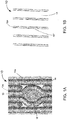
- FIG. 1A illustrates a boiler wall 12 comprising a series of parallel steam tubes 14 separated by a metal membrane 12a. Tube bends 14a, as illustrated in Fig. 1A , are provided to reroute steam tubes 14 around a penetration, which may be for example a 2" (5.08 cm) diameter circular penetration 16'.
- Fig. 1B illustrates an alternative embodiment, which is described in WO 2010/080892 A2 .
- Fig. 1B illustrates a slotted membrane penetration 16" that has approximately a 1 ⁇ 2 inch (1.27 cm) width (equal to the width of the membrane 12a) and is elongate in a direction parallel to the steam pipes 14.
- This arrangement eliminates the need for providing tube bends 14a (as shown in Fig. 1A ), while somewhat aiding in terms of light collection efficiency. Alignment and maintenance of alignment, however, are significantly more difficult than required with the 2 inch (5.08 cm) circular penetration 16' supported by the tube bend approach, as shown in Fig. 1A , and requires a tighter alignment tolerance.
- the embodiments shown in Figs. 1A and 1B are directed to a boiler having steam tubes in the walls of the boiler, the embodiments are not so limited, and may apply to any combustion chamber for which monitoring of combustion properties is desired.
- the shape of the penetration 16 may be any shape (including, but not limited to, circular, substantially circular, elliptical, rectangular, triangular, square, other polygons, etc.), so long as it allows the beam to be effectively projected and received therethrough.
- the invention provides for a steering and alignment system 20 comprising relay lens 22, collimating lens 24, and adjustable stage 26.
- Relay lens 22 is provided in optical communication with collimating lens 24.
- Relay lens 22 is aligned during construction on the axis 30 (shown in, e.g., Fig. 3 ) of penetration 16 (including circular penetration 16', slotted membrane penetration 16", or other-shaped penetrations as described above).
- penetration 16 including circular penetration 16', slotted membrane penetration 16", or other-shaped penetrations as described above.
- steering and alignment system 20 provides for an auto-alignment feature that allows the combination pitch and catch optics to maintain optical alignment with the in-furnace retro-reflector 42 and with itself, even though the steering and alignment system 20 and the retro-reflector 42 are bolted onto a boiler or hostile process chamber which is, itself, subject to movement from thermal effects or wind and vibration.
- Use of the adjustable stage 26 ensures a maximum strength collimated received beam is conveyed to an optically coupled multi-mode fiber 25 (as shown in Figs. 3-5 ).
- the pitch beam is collimated to a diameter of about 5 mm, as opposed to on the order of 20 mm in prior art systems.
- steering and alignment system 20 may be configured to steer the beam toward not only one retro-reflector 42, but each of a plurality of in-furnace retro-reflectors 42 (as shown, e.g., in Figs. 7-9 ), which will be discussed in detail below.
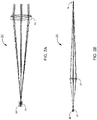
- Fig. 3 schematically illustrates an embodiment of steerable and alignable combination pitch/catch optics that serve as both the transmitter that generates a collimated beam of laser light emerging from an optical fiber 25 and the receiver that captures a collimated beam of light (reflected from one of a plurality of in-furnace retro-reflectors 42), and focuses the beam into the optical fiber 25.
- the combination pitch/catch optics may be mounted in a housing 28 with the leading side having an orifice occupied by a window 21.
- the housing may be an NEMA-4 enclosure to protect the combination pitch/catch optics from the environment.
- the invention includes collimating lens 24 attached to a kinematic tilt stage 26 positioned to tip and tilt the collimating lens 24 about orthogonal axes (i.e., X and Y axes) perpendicular to an optical axis 30 of the steerable and alignable combination pitch/catch optics.
- the collimating lens may be a singlet lens, a doublet lens or include more than two lenses.
- the kinematic tilt stage 26 includes stage 26a, two direct drive stepper motors 26b, and motor drive 26c.
- Stepper motors 26b are configured to tip and tilt the stage 26a about orthogonal axes X and Y that are perpendicular to optical axis 30, and are controlled by a computer via an Ethernet or similar connection. This connection may be through an optical fiber in order to avoid electrical interference.
- the stepper motors 26b hold their positions when power is removed, so optical alignment is not affected by power outages.
- the stepper motors 26b are driven by motor drive 26c.
- the control computer monitors the amount of laser light that is transmitted and detected.
- a discrete alignment wavelength such as a visible or near-infrared light may be provided for continuous or periodic alignment proceedings. Any misalignment will reduce this detected signal.
- the computer measures the detected signal, directs one of the two stepper motors 26b to move a small amount in one direction, then re-measures the detected signal. If the signal increases, the computer directs one of the stepper motors 26b to move again in the same direction until the signal does not increase. The computer then directs the other stepper motor 26b to move along the orthogonal axis to maximize the detected signal, then repeats the whole process for the other sensor head.
- the detector amplifier gain automatically decreases so that the auto-alignment proceeds over several iterations of signal size.
- the auto-alignment system can function with detected powers from nanowatts to milliwatts.
- This "hill-climbing" algorithm is able to align the system after near-total loss of signal, in the presence of substantial noise, and is tolerant of beam blockages, power outages, mechanical shocks, and other disturbances that could cause other alignment systems to misalign to the limits of the control electronics. All that is required for auto alignment is a finite signal with a global maximum in position space. Depending on the specific installation conditions, auto-alignment may occur periodically at set intervals such as every hour or as needed after an extended period, such as days of operation. The control computer may monitor the directed signal and auto-align only when the signal drops below a preset threshold.
- the computer directs the beam to a second in-furnace retro-reflector 42 by directing the stepper motors 26b to "jump" to the second retro-reflector 42, wherein "jumping" is performed in two dimensions by driving stepper motors 26b about the two orthogonal axes (e.g., X and Y axes) that are perpendicular to the optical axis of the steerable and alignable combination pitch/catch optics, in which case the in-furnace retro-reflectors 42 may be arranged so as to lie in multiple planes, in some prearranged pattern, or in arbitrary positions within the furnace.
- the one or more planes may be parallel to a floor of the furnace 10 or parallel with the beam, at a particular time that the beam is being emitted (in such a case, multiple planes would be displaced by predetermined or calculated angles with respect to each other).
- a sight tube 12b has a proximal and a distal end.
- the proximal end is attached to extend normally from an exterior wall 12 of the furnace 10 with penetration 16 communicating with the interior of the sight tube 12b.
- a flange is provided at a distal end of the sight tube 12b. The flange allows the housing 28 to be attached with the leading end abutting the furnace flange with the window 21 in optical communication with the penetration 16.
- a beam may be transmitted into the furnace interior through the penetration 16 and to reflect off at least one in-furnace retro-reflector 42 positioned in furnace 10 back to penetration 16 to pass through the window 21 and be captured by the collimating lens 24.
- multimode optical fiber 25 would be configured to transmit the beam and receive the reflected beam.
- Fig. 4 illustrates an alternative embodiment of steerable and alignable combination pitch/catch optics 20.
- a lens 24 is optically coupled to an optical fiber 25.
- the lens 24 is referred to herein as a "collimating" lens and may be a true collimating lens (that produces a beam of substantially constant diameter).
- the collimating lens 24 may be a "near" collimating lens that provides a slight expansion of the beam 25a.
- the fiber 25 and the collimating lens 24 are mechanically linked together in a fixed relationship and movable by "translation" along orthogonal X-Y axes that are perpendicular to the optical axis 30 of the steerable and alignable combination pitch/catch optics, by a translation mechanism 26.
- the emitted beam 25a is movable by translation to strike select portions of the relay lens 22, which directs the beam through the membrane slot 16 and focuses the beam at about one of a plurality of in-furnace retro-reflectors 42 (as shown, e.g., in Figs. 5-9 ).
- Stepper motors 26b (as shown, e.g., in Fig. 3 ), a computer controller 26c (as also shown, e.g., in Fig. 3 ), and a "hill climbing" algorithm similar to that discussed above with respect to the embodiment of Fig. 3 are operatively associated with the translation mechanism 26 to provide for substantially continuous alignment correction, and to provide for "jumping" between in-furnace retro-reflectors 42.
- Steering and alignment system 20 includes a multimode optical fiber 25, transmit and receive optic 24, adjustable stage 26, noise reduction module 32, optical divider 34, tunable diode laser 36, and detector 38.
- multimode optical fiber 25, transmit and receive optic 24, and adjustable stage 26 may be as described above with respect to any of the embodiments as shown, e.g., in Figs. 2A to 4 .
- the transmit and receive optic 24 may also include only a collimating lens without a relay lens 22.
- Noise reduction module 32 includes any type of noise reduction device.
- noise reduction module 32 may include an averaging component, which may be operatively associated with the multimode optical fiber 25, in order to average modal noise induced signal level variation of light propagating within the multimode optical fiber 25.
- the averaging component 32 is a mechanical vibrator.
- WO 2011/019755 describes various systems and methods for reducing noise in a multimode optical fiber.
- the averaging component may average modal noise induced signal level variations by cyclically varying an index of refraction of the multimode optical fiber over a select period of time, scrambling a light distribution within the multimode optical fiber, or both.
- the index of refraction of the multimode optical fiber may be cyclically varied by cyclically varying the temperature of the multimode optical fiber.
- the index of refraction may be varied or the light distribution within the multimode optical fiber may be scrambled by cyclically and physically manipulating the multimode optical fiber.
- the temperature of the multimode optical fiber may be varied through the action of a thermal element placed in thermal communication with the multimode optical fiber.
- Suitable devices for use as a thermal element include, but are not limited to, a thermoelectric module, a resistive heater, an infrared heater, a chemical heater, a conventional refrigeration device, a chemical cooler, a source of fluid cooled below ambient temperature, or a source of fluid heated above ambient temperature.
- the optical device may include a temperature sensor such as a thermocouple in thermal contact with the multimode optical fiber and a controller receiving input from the temperature sensor and controlling the thermal element.
- the manipulation may include twisting, stretching, or shaking the multimode optical fiber.
- a piezo stretcher may be used to accomplish the cyclical stretching of the multimode optical fiber.
- a motor may be used to cyclically twist a portion of the multimode optical fiber in alternate clockwise and counterclockwise directions with respect to the longitudinal axis of the fiber and relative to a fixed portion of the fiber.
- WO 2005/103781 describes various apparatuses and methods for optical mode noise averaging, including the cyclically varying an index of refraction by one of cyclically varying the temperature of the multimode optical fiber and cyclically manipulating by twisting, stretching, or shaking the multimode optical fiber, as described above.
- the multimode optical fiber 25 is optically coupled to the transmit and receive optic 24.
- the multimode optical fiber 25 is further optically coupled to a tunable diode laser 36, which produces a beam of light at a select wavelength.
- an optical divider 34 is optically associated with the multimode optical fiber 25.
- the optical divider 34 may be, by way of example, a spatial multiplexer or a circulator of the type used in telecommunications applications.
- the function of the optical divider 34 is to divide optical signals received by the transmit and receive optic 24 from an optical signal generated by the tunable diode laser 36 and to deliver the received portion of the signal to a detector 38, which is typically a photo detector sensitive to the frequency of light generated by the tunable diode laser 36.
- the TDLAS sensor 20 is operatively associated with a portion of a combustion furnace 10 with a portion of the furnace 10 including an outer wall 12 and an internal space having at least one in-furnace retro-reflector 42 positioned therein.
- a probe beam 44 generated by the tunable diode laser 36 is directed off the at least one in-furnace retro-reflector 42 so that it reflects back to the transmit and receive optic 24 as illustrated in Fig. 5 .
- a portion of the transmitted beam received by the transmit and receive optic 24 is conveyed by the multimode optical fiber 25 to the optical divider 34 for detection by the detector 38.
- noise reduction component 32 (which may include an averaging component, such as a mechanical vibrator) may be used to reduce modal noise induced signal variation of the light propagating within the multimode optical fiber 25 (e.g., by averaging the modal noise induced signal variations).
- an embodiment 100 is shown in which there is a one-to-one relationship between transmit and receive optics 24 1-to-n and the array of in-furnace retro-reflectors, such that the beam 44 from one transmit and receive optic 24 x is transmitted and reflected off only one of the plurality of in-furnace retro-reflectors 42 back toward said transmit and receive optic 24 x .
- transmit and receive optics 24 1-to-n and 30 in-furnace retro-reflectors 42 would be required.
- Each of the plurality of retro-reflectors may be positioned in a grid 11 of the furnace 10 so as to allow monitoring and control of the combustion for each grid 11.
- an embodiment 200 may utilize the steering and "jumping" technique as described above to "jump" the beam 44 from one transmit and receive optic 24 x to a plurality of in-furnace retro-reflectors 42, which may be arranged in a single plane, in multiple planes, in a predetermined pattern, or in arbitrary positions within the furnace 10 (as described above).
- 5 transmit and receive optics 24 1-to-n may be used to monitor and control the combustion process in a 30-grid furnace, in which each grid 11 has positioned therein one of the 30 retro-reflectors 42.
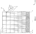
- a plurality of transmit and receive optics 24 (which are each part of a steering and alignment system 20, e.g., as shown and described with respect to Figs. 2A - 5 ) are arranged about half of the perimeter of furnace 10 (e.g., along two walls 12 of a rectangular furnace 10 (as shown, e.g., in Fig. 8 ) or along an arc of a circular or elliptical furnace (not shown)).
- retro-reflectors 42 are positioned in zones or grids 11 among burners 18.
- Embodiments of furnaces wherein the system could be use could include rows of process tubes 50 between the burners 18, for example as is known in Steam Methane Reformer (SMR) furnaces or other similarly designed furnaces with furnace tubes for performing other processes, such as ethylene cracking.
- SMR Steam Methane Reformer
- a schematic plan view of such a furnace is show in Fig. 11 .
- the retro-reflectors are positioned to allow sampling of the combustion zone downstream of a burner or appropriate groupings of burners and adjacent to the process tubes.
- Each transmit and receive optic 24 is configured to steer and "jump" its beam 44 to each of the retro-reflectors 42 in its assigned zones or grids 11.
- the temperature or species concentration is measured along the shortest paths first corresponding to zone 11c.
- transmit and receive optic 24 steers or "jumps" beam 44 to each of the two retro-reflectors 42 in zone or grid 11c.
- the beam 44 can be directed to retro-reflectors 42 that also enable sampling in zone 11b.
- the conditions can be calculated for zone 11b.
- zone 11a conditions can be measured in a similar fashion by directing the measurement beam 44 to retro-reflectors that enable sampling of zones 11a, 11b, and 11c.
- Steering or "jumping" of beam 44 may be in any predetermined order, not necessarily from grid 11c to grid 11b to grid 11a. In such a case, the calculations of the zone conditions may be performed after all the measurements are made.
- the steering or "jumping" of beam 44 by each of the other transmit and receive optics 24 may be performed in a similar manner.
- Fig. 9 illustrates various examples and for monitoring and controlling combustion in a furnace 10, including (in-plane) 1D steerable monitoring as shown in example 300, 2D steerable monitoring as shown in embodiment 400, and multi-plane steerable monitoring as shown in embodiment 500.
- 1D and 2D refers to the dimensional steering from the perspective of the transmit and receive optics 24.
- the transmit and receive optics 24 may be arranged at any desirable height with respect to a floor of the furnace 10, and may be arranged about the sides of the furnace 10 in a similar manner as, e.g., shown in Fig. 8 .
- any combination of 1D steerable monitoring and/or 2D steerable monitoring may be arranged about the furnace 10 (e.g., only 1D steerable monitoring arranged to monitor two or more parallel planes at two or more predetermined heights with respect to the floor of furnace 10; or 2D steerable monitoring arranged to monitor different height zones of furnace 10 with retro-reflectors arranged throughout substantially all or a portion of the interior of furnace 10; etc.).
- burners 18 may be positioned in any location of the interior of the furnace - including on the floor of the furnace 10 with flames emitted toward the ceiling of the furnace 10, and on the side of the furnace 10 with flames emitted toward an opposite side of the furnace 10.
- radiant wall burners may be used in which case flames are directed along the refractory lined furnace walls by burners mounted on these same walls. The purpose of these burners is to heat the refractory which then heats the tubes primarily by radiated heat transfer.
- the retro-reflectors would preferably be arranged generally down-flame of the burners 18 to the extent possible (e.g., on the opposite side of the furnace with respect to the burners) in the various possible configurations as described above or in any configuration that allows for monitoring and control of the combustion process in furnace 10.
- retro-reflectors 42 include that fewer paths are required, thus avoiding complexities of angled paths in a tightly packed furnace.
- the laser beam 44 used to measure each cell must propagate out and back, thereby doubling the path length ("double-pass laser path") and increasing absorption signal strength. Stronger absorption signal reduces the deleterious effects of noise sources, such as modal, etalon, and detector noise.
- "self-aligned laser paths" may be obtained.
- retro-reflecting targets in the furnace redirect the incident laser light back towards the source, where the sensor head collects the return light and sends it on to optical detectors.
- the sensor head needs to direct the transmitted beam towards the retro-reflector, but after that, no additional alignment is required.
- the auto-alignment process discussed above would be to align the beam with one of the retro-reflectors.
- in-furnace retro-reflectors For effective use within a furnace, which can generally reach temperatures of 1000 to 1300 °C near the furnace gas exit, in-furnace retro-reflectors must be able to withstand these high temperatures, as well as being able to withstand an oxidizing environment. Not only does one need an optical element that can survive within that environment, one likely needs mounting or superstructure elements to hold the optical element in place.
- Two potential materials that may be suitable for in-furnace retro-reflectors include sapphire, which has a melting point of 2030 °C, and quartz, which has a melting point of 1670-1713 °C. Thus, both sapphire and quartz can withstand the high temperatures of the furnace. As oxides, both sapphire and quartz are stable in oxidizing environments. Other materials may also work, but may be subject to cost and availability issues.
- a corner cube retro-reflector - a classic retro-reflector element - may be used. Corner cubes made of standard optical materials, including sapphire, are widely commercially available. The corner cube takes advantage of total internal reflection at the back side of the element so that its back reflection efficiency is very high. A corner cube has no optical power, so a diverging beam entering the cube exits as a beam with the same divergence. Thus, the highest retro-reflection efficiency back to the source occurs when the beam incident on the corner cube is collimated (plane wave illumination).
- a cat's eye retro-reflecting sphere may be used.
- a sphere with index of refraction 2.0 also retro-reflects an incident beam.
- the rays from a collimated illumination beam form a focus spot on the back surface of the sphere, where a portion of those rays reflects back along the same angle as the incident ray.
- Optical quality spheres generally cost less than a comparably sized retro-reflector.
- One disadvantage of the cat's eye retro-reflector is lower overall reflectivity compared to that of a corner cube. Unlike in a corner cube, light bouncing off the back surface of the cat's eye is not totally internally reflected. The reflectivity of the back surface of the cat's eye depends on the index of refraction of the material but will be in the range of 4 - 8%. In lower temperature applications, according to some embodiments, partially reflective coatings, such as gold, may be applied to the sphere to increase its back reflectance.
- an array of smaller retro-reflectors may be used.
- An array of retro-reflectors 42' for retro-reflecting a single beam 44 will tend to act more like a phase conjugate mirror. That is, regardless of whether the illuminating beam is collimated, diverging, or converging, the retro-reflected beam will tend to retrace its incident path back to the source. So, a diverging source beam will be retro-reflected as a beam converging back towards the source.
- the smaller retro-reflecting elements will contribute to more scattering on reflection.
- each retro-reflector element will produce an interference pattern on the reflected beam.
- This interference pattern would be observed as intensity fringes in the wavelength-scanned TDLAS signal.
- a single, large retro-reflector would be expected to have large, well-defined fringes because the number of interfering waves would be small.
- An array of small retro-reflectors would produce many more interfering waves, and the resultant fringes in the TDLAS signal would likely be of smaller amplitude, be less stationary in time, and be easier to eliminate through signal averaging and mode scrambling.
- an array of smaller elements may cost less than a single, large element.
- each of discrete retro-reflectors or array retro-reflectors being positioned at discrete locations within the furnace for which one may desire to monitor and/or control combustion processes
- one or more spanning retro-reflecting surfaces comprising an array of discrete small retro-reflector elements may be used where two or more retro-reflecting surfaces of each spanning retro-reflecting surface may cover a first location, a second location, a third location, and so on, in the furnace for which one may desire to monitor and/or control combustion processes.
- the kinematic stage would be configured so as to "jump" the beam from one retro-reflecting surface located at the first location to another retro-reflecting surface located at the second location, and so on.
- a mounting superstructure may be used.
- ceramics are probably the best material as they can withstand both the high temperatures and the oxidizing environment. Ceramics may be machined or molded and fired to the desired shape. A ceramic superstructure could be formed with slots or other features to capture and hold retro-reflector optics.
- adhesives will not withstand furnace temperatures, sapphire or quartz optics may be fused to a ceramic mounting structure, according to one embodiment. Alternatively, according to another embodiment, optics could be captured/held in slots or other features formed into the ceramics.
- nichrome wire may be used.
- a common nichrome alloy includes 80% nickel and 20% chromium, has a melting point of approximately 1400 °C, and is relatively oxidation resistant due to a protective layer of chromium oxide.
- arrays of retro-reflecting optics are wired together through holes in the optics (like beads on a string) or by creating wire cages to capture each element. The nichrome wire could then be tied into mounting features on the furnace or to the ceramic mounts.For down-fired furnaces, according to some embodiments, where the flue gas exits 52 are located at the bottom of the furnace (see Fig.
- a hold-down feature such as a ceramic pin that fits into a corresponding hole in the floor, is provided to mount the retro-reflectors on the bottom or floor of the furnace.
- the retro-reflector mounts may be located opposite the burners, where the flue gas exits are typically located, so that the laser paths are located where combustion is just complete.
- a gird may be close-coupled to the burner wall.
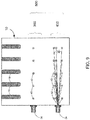
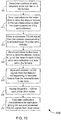
- a flowchart is shown illustrating an example 600 for monitoring and calculating combustion properties for zones within the interior of the furnace.
- a general purpose or application specific computer may be used to determine the location of all the retro-reflectors positioned within the interior of a particular furnace. This may be accomplished, for example, by accessing a database on which is stored the locations of the retro-reflectors.
- a scanning beam could be used to scan the interior of the furnace, where the location of a retro-reflector is determined when a reflected beam (e.g., a back-reflected beam or a beam reflected to a separate detector) is detected.
- Step 610 the computer sends instructions to the motor drive 26c to drive stepper motors 26b to tilt stage 26a so as to "steer" the beam to one of the retro-reflectors 42(either a single, large retro-reflector or an array of smaller retro-reflecting elements). Auto-alignment, as described above, may be performed in order to ensure an optimal signal reflected from the retro-reflector 42.
- Step 615 the computer stores and processes the TDLAS signal from the detector corresponding to the reflected beam from the retro-reflector 42.
- Step 620 the computer sends instructions to the motor drive 26c to drive the stepper motors 26b to tilt stage 26a so as to "jump" the beam to each of the other retro-reflectors 42 in a predetermined zone of the furnace. Auto-alignment may also be performed at this time.
- Step 625 the computer stores and processes the TDLAS signals from the detector corresponding to the reflected beam from all the retro-reflectors 42 in the zone.
- Step 630 Steps 620 - 625 are repeated for each of the other zones for which this particular transmit/receive optic is assigned.
- Step 635 the computer calculates the combustion characteristics for each zone taking into account the calculations for other zones, in a manner similar to that described above with respect to Fig. 8 . Steps 605-635 may subsequently be repeated for each transmit/receive optic.
- Software for controlling the computer may be stored on any recordable medium including, but not limited to, a floppy disk, a flash memory drive, a database, a server, an SD memory drive, a hard drive, etc.
- retro-reflectors including, but not limited to, corner cube, cat's eye, or other types of retro-retroflectors, etc.
- optical mirrors or arrays or small optical mirrors may also be used to reflect the beam either back to the source optic or to a different optic mounted on the exterior of the wall of the furnace.
- such embodiments may be more difficult align a transmitted beam to be directed off the mirrors to the receiving optic than embodiments using a single transmit/receive optic and retro-reflectors.
Landscapes
- Engineering & Computer Science (AREA)
- Physics & Mathematics (AREA)
- Chemical & Material Sciences (AREA)
- General Physics & Mathematics (AREA)
- General Engineering & Computer Science (AREA)
- Mechanical Engineering (AREA)
- Combustion & Propulsion (AREA)
- Spectroscopy & Molecular Physics (AREA)
- Analytical Chemistry (AREA)
- Pathology (AREA)
- Immunology (AREA)
- General Health & Medical Sciences (AREA)
- Biochemistry (AREA)
- Life Sciences & Earth Sciences (AREA)
- Health & Medical Sciences (AREA)
- Optics & Photonics (AREA)
- Investigating Or Analysing Materials By Optical Means (AREA)
Applications Claiming Priority (2)
| Application Number | Priority Date | Filing Date | Title |
|---|---|---|---|
| US201261635733P | 2012-04-19 | 2012-04-19 | |
| PCT/US2013/032479 WO2013158311A1 (en) | 2012-04-19 | 2013-03-15 | In-furnace retro-reflectors with steerable tunable diode laser absorption spectrometer |
Publications (3)
| Publication Number | Publication Date |
|---|---|
| EP2839265A1 EP2839265A1 (en) | 2015-02-25 |
| EP2839265A4 EP2839265A4 (en) | 2015-12-30 |
| EP2839265B1 true EP2839265B1 (en) | 2017-07-26 |
Family
ID=49383941
Family Applications (1)
| Application Number | Title | Priority Date | Filing Date |
|---|---|---|---|
| EP13779007.7A Active EP2839265B1 (en) | 2012-04-19 | 2013-03-15 | In-furnace retro-reflectors with steerable tunable diode laser absorption spectrometer |
Country Status (8)
| Country | Link |
|---|---|
| US (1) | US9366621B2 (ja) |
| EP (1) | EP2839265B1 (ja) |
| JP (1) | JP6196289B2 (ja) |
| KR (1) | KR101994509B1 (ja) |
| CN (1) | CN104471376B (ja) |
| CA (1) | CA2871072C (ja) |
| ES (1) | ES2644601T3 (ja) |
| WO (1) | WO2013158311A1 (ja) |
Families Citing this family (15)
| Publication number | Priority date | Publication date | Assignee | Title |
|---|---|---|---|---|
| US9983127B2 (en) * | 2013-09-03 | 2018-05-29 | Nanyang Technological University | Optical detection device and optical detection method |
| US10371378B2 (en) | 2013-12-20 | 2019-08-06 | John Zink Company, Llc | Method and apparatus for monitoring port blockage for TDLAS measurements in harsh environments |
| US10508807B2 (en) * | 2014-05-02 | 2019-12-17 | Air Products And Chemicals, Inc. | Remote burner monitoring system and method |
| WO2017075453A1 (en) * | 2015-10-29 | 2017-05-04 | Paneratech, Inc. | Asset life optimization and monitoring system |
| CN105403373A (zh) * | 2015-12-20 | 2016-03-16 | 安徽中科智泰光电测控科技有限公司 | 一种扩散式天然气站场瓦斯泄露激光在线监测预警装置 |
| CN105841824B (zh) * | 2016-03-23 | 2019-01-29 | 东南大学 | 一种非接触便携式温度实时测量装置 |
| CN106017725B (zh) * | 2016-05-26 | 2019-07-09 | 中国人民解放军战略支援部队航天工程大学 | 一种适用于燃烧流场气体二维重建的测量装置 |
| WO2018005908A1 (en) * | 2016-07-01 | 2018-01-04 | Molex, Llc | Module for gas analysis system |
| US9761113B1 (en) | 2016-07-20 | 2017-09-12 | Banner Engineering Corp. | Light curtain protection system featuring a passive optical module |
| JP6717337B2 (ja) * | 2018-04-06 | 2020-07-01 | 横河電機株式会社 | ガス分析装置 |
| EP3811132B1 (en) | 2018-06-18 | 2023-11-15 | Dolby Laboratories Licensing Corporation | Modal-noise mitigator and associated method |
| KR102130341B1 (ko) | 2018-09-06 | 2020-07-07 | 한국생산기술연구원 | 미세먼지 전구물질 농도 및 온도의 2차원 측정 및 이의 능동제어 방법 |
| WO2020071570A1 (ko) | 2018-10-05 | 2020-04-09 | 한국생산기술연구원 | 미세먼지 전구물질 농도 및 온도의 2차원 측정 및 이의 능동제어 방법 |
| CN113544559A (zh) * | 2019-04-15 | 2021-10-22 | 正点技术有限公司 | 光学火焰传感器 |
| KR102226368B1 (ko) * | 2019-11-18 | 2021-03-11 | 한국생산기술연구원 | 음향 정상파를 포함하는 tdlas 기체 검출 장치 |
Family Cites Families (166)
| Publication number | Priority date | Publication date | Assignee | Title |
|---|---|---|---|---|
| US2163713A (en) | 1938-04-22 | 1939-06-27 | Soss Joseph | Concealed hinge |
| US2841122A (en) | 1953-03-12 | 1958-07-01 | Babcock & Wilcox Co | Wall tube fluid heater with a releasably anchored enclosure |
| US2930893A (en) * | 1956-05-21 | 1960-03-29 | Lane B Carpenter | Long path infrared detection of atmospheric contaminants |
| US3754533A (en) | 1971-11-24 | 1973-08-28 | Babcock & Wilcox Ltd | Tube support system |
| US3778170A (en) | 1972-11-02 | 1973-12-11 | Gen Electric | Borescope guide tube |
| US4037113A (en) | 1975-04-11 | 1977-07-19 | Forney Engineering Company | Flame detector |
| US4028081A (en) | 1975-12-11 | 1977-06-07 | Bell Telephone Laboratories, Incorporated | Method for manufacturing helical optical fiber |
| US4011403A (en) | 1976-03-30 | 1977-03-08 | Northwestern University | Fiber optic laser illuminators |
| DE2730508A1 (de) | 1977-07-06 | 1979-01-25 | Bbc Brown Boveri & Cie | Mess- und/oder ueberwachungseinrichtung fuer aenderungen der spaltweite zwischen relativ zueinander bewegbaren bauelementen |
| US4305640A (en) | 1978-11-24 | 1981-12-15 | National Research Development Corporation | Laser beam annealing diffuser |
| US4360372A (en) | 1980-11-10 | 1982-11-23 | Northern Telecom Limited | Fiber optic element for reducing speckle noise |
| US4432286A (en) | 1982-05-19 | 1984-02-21 | The United States Of America As Represented By The United States Department Of Energy | Combustion pinhole camera system |
| JPS58213235A (ja) * | 1982-06-04 | 1983-12-12 | Fujitsu Ltd | ガス検出方式 |
| DD219059A3 (de) | 1982-09-14 | 1985-02-20 | Freiberg Brennstoffinst | Periskop fuer hochtemperatur-reaktoren |
| US4573761A (en) | 1983-09-14 | 1986-03-04 | The Dow Chemical Company | Fiber-optic probe for sensitive Raman analysis |
| SE453017B (sv) | 1985-06-13 | 1988-01-04 | Opsis Ab Ideon | Sett och anordning for bestemning av parametrar for gasformiga emnen som er nervarande vid forbrenningsprocesser och andra processer som sker vid hog temperatur |
| US4672198A (en) | 1986-01-24 | 1987-06-09 | At&T Company And At&T Bell Laboratories | Signal sampler microbending fiber test clip |
| US4659195A (en) | 1986-01-31 | 1987-04-21 | American Hospital Supply Corporation | Engine inspection system |
| US4712888A (en) | 1986-08-04 | 1987-12-15 | Trw Inc. | Spatial light modulator systems |
| US4915468A (en) | 1987-02-20 | 1990-04-10 | The Board Of Trustees Of The Leland Stanford Junior University | Apparatus using two-mode optical waveguide with non-circular core |
| US4741586A (en) | 1987-02-20 | 1988-05-03 | The Board Of Trustees Of The Leland Stanford Junior University | Dynamic coupler using two-mode optical waveguides |
| JPS63133035U (ja) | 1987-02-23 | 1988-08-31 | ||
| JPH0239145U (ja) | 1988-09-09 | 1990-03-15 | ||
| US4989979A (en) | 1989-01-17 | 1991-02-05 | Board Of Regents, The University Of Texas System | Optical fiber sensors with full common-mode compensation and measurand sensitivity enhancement |
| US4980763A (en) | 1989-06-12 | 1990-12-25 | Welch Allyn, Inc. | System for measuring objects viewed through a borescope |
| ATE133079T1 (de) | 1989-12-27 | 1996-02-15 | Ciba Geigy Ag | Vorrichtung zum homogenisieren der inhomogenen lichtverteilung eines laserstrahllichtbündels |
| US5042905A (en) | 1990-06-15 | 1991-08-27 | Honeywell Inc. | Electrically passive fiber optic position sensor |
| CA2087439C (en) * | 1990-07-16 | 1996-07-09 | Orman A. Simpson | Ftir remote sensor apparatus and method |
| IT1251246B (it) | 1991-08-27 | 1995-05-05 | Sie Systems Spa | Dispositivo per a rivelazione della presenza e della qualita' della fiamma attraverso la captazione e l'analisi di radiazioni elettromagnetiche di diversa lunghezza d'onda |
| US5291013A (en) | 1991-12-06 | 1994-03-01 | Alamed Corporation | Fiber optical monitor for detecting normal breathing and heartbeat motion based on changes in speckle patterns |
| US5436444A (en) | 1991-12-06 | 1995-07-25 | Alamed Corporation | Multimode optical fiber motion monitor with audible output |
| FI90469C (fi) | 1992-02-25 | 1994-02-10 | Imatran Voima Oy | Sovitelma tulipesäkamerassa |
| US5468239A (en) | 1992-04-13 | 1995-11-21 | Sorenson Laboratories, Inc. | Apparatus and methods for using a circumferential light-emitting surgical laser probe |
| WO1993022706A1 (en) | 1992-04-28 | 1993-11-11 | The Furukawa Electric Co., Ltd. | External modulator for optical communication |
| US5298047A (en) | 1992-08-03 | 1994-03-29 | At&T Bell Laboratories | Method of making a fiber having low polarization mode dispersion due to a permanent spin |
| US5798840A (en) | 1992-08-05 | 1998-08-25 | The Aerospace Corporation | Fast optical absorption tomography apparatus and method |
| GB9217705D0 (en) | 1992-08-20 | 1992-09-30 | Ici Plc | Data-recordal using laser beams |
| WO1994011708A1 (en) | 1992-11-06 | 1994-05-26 | Martin Marietta Corporation | Interferometric optical sensor read-out system |
| US5408554A (en) | 1993-12-17 | 1995-04-18 | Porta System Corporation | Fiber optic coupling |
| US5448071A (en) | 1993-04-16 | 1995-09-05 | Bruce W. McCaul | Gas spectroscopy |
| US5396506A (en) | 1993-12-09 | 1995-03-07 | United Technologies Corporation | Coupled multiple output fiber laser |
| US5515158A (en) | 1994-02-01 | 1996-05-07 | The United States Of America As Represented By The Administrator Of The National Aeronautics And Space Administration | Retroreflection focusing schlieren system |
| US5445964A (en) * | 1994-05-11 | 1995-08-29 | Lee; Peter S. | Dynamic engine oil and fuel consumption measurements using tunable diode laser spectroscopy |
| US5627934A (en) | 1994-08-03 | 1997-05-06 | Martin Marietta Energy Systems, Inc. | Concentric core optical fiber with multiple-mode signal transmission |
| DE4446425A1 (de) | 1994-12-23 | 1996-06-27 | Siemens Ag | Verfahren und Anordnung zum Messen eines Magnetfeldes unter Ausnutzung des Faraday-Effekts mit Kompensation von Intensitätsänderungen und Temperatureinflüssen |
| CN1163665A (zh) | 1994-12-23 | 1997-10-29 | 西门子公司 | 利用法拉第效应、带有对强度变化和温度影响进行补偿的测量磁场的方法和装置 |
| DE19503929A1 (de) | 1995-02-07 | 1996-08-08 | Ldt Gmbh & Co | Farbbilderzeugungssysteme |
| US5598264A (en) | 1995-05-18 | 1997-01-28 | Failes; Michael | Noise compensated interferometric measuring device and method using signal and reference interferometers |
| US5621213A (en) | 1995-07-07 | 1997-04-15 | Novitron International Inc. | System and method for monitoring a stack gas |
| JP3860237B2 (ja) | 1995-07-26 | 2006-12-20 | 富士通株式会社 | 偏波分散の抑圧特性を持つ光ファイバ及びその製造方法 |
| CA2158516A1 (en) | 1995-07-28 | 1997-01-29 | Shachar Nadler | Method and apparatus for monitoring trace constituents in a fluid |
| EP0785913B1 (en) | 1995-08-16 | 2000-05-31 | Plasma Optical Fibre B.V. | Optical fiber with low polarisation mode dispersion |
| US5748325A (en) | 1995-09-11 | 1998-05-05 | Tulip; John | Gas detector for plural target zones |
| JPH0973020A (ja) | 1995-09-05 | 1997-03-18 | Toshiba Corp | 光合分波器 |
| EP0766080A1 (en) | 1995-09-29 | 1997-04-02 | FINMECCANICA S.p.A. AZIENDA ANSALDO | System and method for monitoring combustion and pollutants by means of laser diodes |
| JPH09152126A (ja) | 1995-11-30 | 1997-06-10 | Tokyo Gas Co Ltd | 火炎検知装置 |
| TW337553B (en) | 1995-12-20 | 1998-08-01 | Voest Alpine Ind Anlagen | Method for determination of electromagnetic waves originating from a melt |
| US5742715A (en) | 1995-12-21 | 1998-04-21 | Lucent Technologies Inc. | Optical fiber status analyzer and related methods |
| GB2309317A (en) | 1996-01-17 | 1997-07-23 | Univ Southampton | Optical fibre device |
| US5841546A (en) | 1996-03-01 | 1998-11-24 | Foster-Miller, Inc. | Non-contact spectroscopy system and process |
| US5732166A (en) | 1996-03-11 | 1998-03-24 | Hamann; Oliver | High temperature-resistant optical sensing apparatus and method of making |
| US5717209A (en) | 1996-04-29 | 1998-02-10 | Petrometrix Ltd. | System for remote transmission of spectral information through communication optical fibers for real-time on-line hydrocarbons process analysis by near infra red spectroscopy |
| US5828797A (en) | 1996-06-19 | 1998-10-27 | Meggitt Avionics, Inc. | Fiber optic linked flame sensor |
| US5993194A (en) | 1996-06-21 | 1999-11-30 | Lemelson; Jerome H. | Automatically optimized combustion control |
| US5774610A (en) | 1996-07-08 | 1998-06-30 | Equitech Int'l Corporation | Fiber optic probe |
| AU4379197A (en) | 1996-08-16 | 1998-03-06 | Novartis Ag | Optical detector |
| US6169830B1 (en) | 1996-08-26 | 2001-01-02 | Arroyo Optics, Inc. | Methods of fabricating grating assisted coupler devices |
| US5841915A (en) | 1996-11-04 | 1998-11-24 | Honeywell Inc. | Apparatus for determining the effect of modal noise on a communication system by affecting an optical fiber discontinuity |
| US5805318A (en) | 1996-11-04 | 1998-09-08 | Honeywell Inc. | Apparatus for determining the effect of modal noise on a communication system by flexing an optical fiber |
| GB2320155B (en) * | 1996-12-03 | 2000-11-01 | Chelsea Instr Ltd | Method and apparatus for the imaging of gases |
| US6046809A (en) * | 1998-02-04 | 2000-04-04 | S3 Incorporated | Real-time in situ multiple gas species sensing method |
| JPH10301153A (ja) | 1997-04-23 | 1998-11-13 | Sony Corp | 光源装置とこれを用いた光学測定装置および露光装置 |
| US6787758B2 (en) | 2001-02-06 | 2004-09-07 | Baker Hughes Incorporated | Wellbores utilizing fiber optic-based sensors and operating devices |
| US6124597A (en) | 1997-07-07 | 2000-09-26 | Cedars-Sinai Medical Center | Method and devices for laser induced fluorescence attenuation spectroscopy |
| EP1003595A1 (de) | 1997-08-02 | 2000-05-31 | Roger Marcel Humbel | Sicherheitsbindung für ein snowboard |
| US6016372A (en) | 1997-10-16 | 2000-01-18 | World Precision Instruments, Inc. | Chemical sensing techniques employing liquid-core optical fibers |
| US5930029A (en) | 1997-12-02 | 1999-07-27 | Sdl, Inc. | Optical fiber amplifier with optimized power conversion |
| US5960129A (en) | 1997-12-22 | 1999-09-28 | Bayer Corporation | Method and apparatus for detecting liquid and gas segment flow through a tube |
| WO1999045419A1 (en) | 1998-03-04 | 1999-09-10 | Sdl, Inc. | Optical couplers for multimode fibers |
| US6064417A (en) | 1998-03-31 | 2000-05-16 | Eastman Kodak Company | Laser printer using multiple sets of lasers with multiple wavelengths |
| WO1999053297A1 (en) | 1998-04-14 | 1999-10-21 | Instrumentarium Corporation | Sensor assembly and method for measuring nitrogen dioxide |
| US7398119B2 (en) | 1998-07-13 | 2008-07-08 | Childrens Hospital Los Angeles | Assessing blood brain barrier dynamics or identifying or measuring selected substances, including ethanol or toxins, in a subject by analyzing Raman spectrum signals |
| JP4038631B2 (ja) | 1998-08-28 | 2008-01-30 | 株式会社堀場製作所 | 半導体レーザ分光法を用いた温度・濃度・化学種の高速計測方法および計測システム |
| US6160255A (en) | 1998-10-05 | 2000-12-12 | The United States Of America As Represented By The Secretary Of The Army | Laser-based photoacoustic sensor and method for trace detection and differentiantion of atmospheric NO and NO2 |
| DE19847832C1 (de) | 1998-10-16 | 1999-11-04 | Siemens Ag | Verfahren zum Überwachen eines optischen Systems mit einer unmittelbar an einem Verbrennungsraum angeordneten Frontlinse und Überwachungsmodul |
| JP2000121558A (ja) | 1998-10-16 | 2000-04-28 | Mitsubishi Heavy Ind Ltd | 計測装置 |
| DE69924639T2 (de) | 1998-11-11 | 2006-02-09 | The University Of Manchester | Überwachung der verteilung und mischung eines chemischen spezies |
| US6510265B1 (en) | 1999-04-21 | 2003-01-21 | Lucent Technologies Inc. | High-speed multi mode fiber optic link |
| US6263127B1 (en) | 1999-05-13 | 2001-07-17 | Lucent Technologies Inc. | Free-space/arrayed-waveguide router |
| US6042365A (en) | 1999-06-28 | 2000-03-28 | Chen; Yaosheng | Fuel combustion monitoring apparatus and method |
| US6396056B1 (en) * | 1999-07-08 | 2002-05-28 | Air Instruments And Measurements, Inc. | Gas detectors and gas analyzers utilizing spectral absorption |
| US6304692B1 (en) | 1999-09-03 | 2001-10-16 | Zolo Technologies, Inc. | Echelle grating dense wavelength division multiplexer/demultiplexer with two dimensional single channel array |
| US6294389B1 (en) * | 1999-11-01 | 2001-09-25 | General Motors Corporation | Furnace for an engine exhaust measurement system |
| US6351587B1 (en) | 1999-11-12 | 2002-02-26 | Lucent Technologies Inc. | Multi-fiber digital delay line |
| US6422043B1 (en) | 1999-11-16 | 2002-07-23 | Fitel Usa Corp. | Method of making an improved multimode optical fiber and fiber made by method |
| AU779659B2 (en) | 2000-02-08 | 2005-02-03 | Cornell Research Foundation Inc. | Multiphoton excitation through optical fibers for fluorescence spectroscopy |
| US6363190B1 (en) | 2000-02-11 | 2002-03-26 | New Focus, Inc. | Polarization insensitive fused fiber coupler method and apparatus |
| US20020031737A1 (en) | 2000-03-10 | 2002-03-14 | American Air Liquide, Inc. | Method for continuously monitoring chemical species and temperature in hot process gases |
| KR100353442B1 (ko) | 2000-03-22 | 2002-09-19 | 삼성전자 주식회사 | 산란 손실이 감소된 다중모드 광섬유 구조 |
| US6455851B1 (en) | 2000-03-28 | 2002-09-24 | Air Instruments And Measurement, Inc. | Spectroscopic remote sensing exhaust emission monitoring system |
| US6385372B1 (en) | 2000-04-19 | 2002-05-07 | Tera Fiberoptics, Inc. | Fiber optical coupler fabrication and system |
| CN1195202C (zh) | 2000-09-15 | 2005-03-30 | 饶云江 | 集成式光纤应变与温度传感器装置 |
| US6519385B1 (en) | 2000-09-27 | 2003-02-11 | The Boeing Company | Method and apparatus for controllably positioning an optical fiber to introduce a phase shift |
| US6473705B1 (en) | 2000-10-10 | 2002-10-29 | General Electric Company | System and method for direct non-intrusive measurement of corrected airflow |
| US6959129B2 (en) | 2000-12-22 | 2005-10-25 | Metrophotonics Inc. | Bidirectional multiplexer and demultiplexer based on a single echelle waveguide grating |
| US20020158202A1 (en) | 2001-01-08 | 2002-10-31 | Webber Michael E. | Laser-based sensor for measuring combustion parameters |
| US6701753B2 (en) | 2001-02-11 | 2004-03-09 | Fitel Usa Corp. | Method and apparatus for making improved optical fiber preforms and optical fiber therefrom |
| US6766070B2 (en) | 2001-04-27 | 2004-07-20 | The United States Of America As Represented By The Secretary Of The Navy | High power fiber optic modulator system and method |
| JP2003004633A (ja) | 2001-06-22 | 2003-01-08 | Nissan Motor Co Ltd | エンジンの燃料濃度測定装置 |
| JP2003084324A (ja) | 2001-09-12 | 2003-03-19 | Nippon Telegr & Teleph Corp <Ntt> | マルチモード導波路 |
| US6950452B2 (en) | 2001-09-28 | 2005-09-27 | The Furukawa Electric Co., Ltd. | Semiconductor laser module and method for simultaneously reducing relative intensity noise (RIN) and stimulated brillouin scattering (SBS) |
| JP2003156698A (ja) | 2001-11-22 | 2003-05-30 | Toshiba Corp | レーザ光源装置 |
| KR100417000B1 (ko) | 2001-12-03 | 2004-02-05 | 삼성전자주식회사 | 저 편광 모드 분산을 위한 장치 |
| US6762835B2 (en) | 2002-03-18 | 2004-07-13 | Mississippi State University | Fiber optic laser-induced breakdown spectroscopy sensor for molten material analysis |
| JP3616070B2 (ja) | 2002-04-30 | 2005-02-02 | 三菱重工業株式会社 | ガス温度非接触計測装置 |
| US20030210398A1 (en) | 2002-05-13 | 2003-11-13 | Robert Augustine | System and method for controlling a light source for cavity ring-down spectroscopy |
| JP2004096088A (ja) | 2002-07-10 | 2004-03-25 | Fuji Photo Film Co Ltd | 合波レーザー光源および露光装置 |
| US7618825B2 (en) | 2002-07-12 | 2009-11-17 | Alstom Technology Ltd. | Method for influencing and monitoring the oxide layer on metallic components of hot CO2/H20 cycle systems |
| CN1723332B (zh) | 2002-08-30 | 2010-10-27 | 高速传感器有限公司 | 采用纤维光学导线和传感器的测井系统 |
| WO2004050573A1 (en) | 2002-09-25 | 2004-06-17 | Giacomo Stefano Roba | Process for producing an optical fiber having a low polarization mode dispersion |
| JP2004117236A (ja) | 2002-09-27 | 2004-04-15 | Fuji Photo Film Co Ltd | 光学特性測定装置 |
| WO2004046869A2 (en) | 2002-11-18 | 2004-06-03 | William B Spillman, Jr | System, device, and method for detecting perturbations |
| KR100469736B1 (ko) | 2002-11-21 | 2005-02-02 | 삼성전자주식회사 | 다파장 레이징 광원에 파장 잠김된 페브리-페롯 레이저장치 및 이를 이용한 광 전송장치 |
| FR2847670B1 (fr) | 2002-11-26 | 2005-06-10 | Sc2N Sa | Detecteur par voie optique de la presence de bulles de gaz dans un liquide |
| JP2004204787A (ja) | 2002-12-26 | 2004-07-22 | Toyota Central Res & Dev Lab Inc | 動力発生装置の制御装置 |
| US20040160596A1 (en) | 2003-02-19 | 2004-08-19 | Pactonix, Inc. | Apparatus and method to accurately monitor signal quality in optical signal transmission systems |
| AU2004227359B2 (en) * | 2003-03-31 | 2009-07-30 | Zolo Technologies, Inc. | Method and apparatus for the monitoring and control of combustion |
| US7075629B2 (en) | 2003-05-12 | 2006-07-11 | Honeywell International Inc. | High temperature pyrometer |
| JP2004354671A (ja) | 2003-05-29 | 2004-12-16 | Nikon Corp | スペックルパターン分散装置及びレーザ光照射装置 |
| EP1541808A1 (de) | 2003-12-11 | 2005-06-15 | Siemens Aktiengesellschaft | Turbinenbauteil mit Wärmedämmschicht und Erosionsschutzschicht |
| KR20060132664A (ko) | 2003-12-30 | 2006-12-21 | 프리즈미안 카비 에 시스테미 에너지아 에스 알 엘 | 저편광모드분산 광섬유 링크 및 그 제조방법 |
| US7158552B2 (en) | 2004-02-13 | 2007-01-02 | Lucent Technologies Inc. | Low relative intensity noise fiber grating type laser diode |
| US7787728B2 (en) | 2004-03-31 | 2010-08-31 | Zolo Technologies, Inc. | Optical mode noise averaging device |
| WO2005103781A1 (en) | 2004-03-31 | 2005-11-03 | Zolo Technologies, Inc. | Optical mode noise averaging device |
| US7502110B2 (en) * | 2004-07-21 | 2009-03-10 | Lighthouse Worldwide Solutions, Inc | Design for particle sensor system |
| US7080504B2 (en) | 2004-07-23 | 2006-07-25 | Northrop Grumman Corporation | Laser augmented turbojet propulsion system |
| US7340129B2 (en) | 2004-08-04 | 2008-03-04 | Colorado State University Research Foundation | Fiber laser coupled optical spark delivery system |
| US7324203B2 (en) | 2005-02-08 | 2008-01-29 | General Electric Company | Method and apparatus for optical detection for multi-phase combustion systems |
| US7291856B2 (en) | 2005-04-28 | 2007-11-06 | Honeywell International Inc. | Sensor and methods for measuring select components in moving sheet products |
| US7075653B1 (en) | 2005-04-29 | 2006-07-11 | Heath Consultants Incorporated | Method and apparatus for laser-based remote methane leak detection |
| WO2007007389A1 (ja) | 2005-07-11 | 2007-01-18 | Mitsubishi Denki Kabushiki Kaisha | スペックル除去光源および照明装置 |
| EP1952003B1 (en) | 2005-11-04 | 2014-07-16 | Zolo Technologies, Inc. | Method and apparatus for spectroscopic measurements in the combustion zone of a gas turbine engine |
| US7650050B2 (en) | 2005-12-08 | 2010-01-19 | Alstom Technology Ltd. | Optical sensor device for local analysis of a combustion process in a combustor of a thermal power plant |
| US7864322B2 (en) | 2006-03-23 | 2011-01-04 | The Research Foundation Of State University Of New York | Optical methods and systems for detecting a constituent in a gas containing oxygen in harsh environments |
| US7440097B2 (en) | 2006-06-27 | 2008-10-21 | General Electric Company | Laser plasma spectroscopy apparatus and method for in situ depth profiling |
| EP1887343A1 (en) * | 2006-08-11 | 2008-02-13 | Geoservices | Device for quantifying the content of at least one gaseous constituent contained in a gaseous sample from a fluid, related assembly and process |
| GB0623835D0 (en) | 2006-11-29 | 2007-01-10 | Cascade Technologies Ltd | Multi mode fibre perturber |
| RU2336573C1 (ru) | 2006-12-14 | 2008-10-20 | Министерство образования и науки Российской Федерации Федеральное агентство по образованию Государственное образовательное учреждение высшего профессионального образования Казанский государственный технический университет им. А.Н.ТУПОЛЕВА (КГТУ-КАИ) | Пожарный извещатель |
| WO2008103837A1 (en) | 2007-02-22 | 2008-08-28 | Zolo Technologies, Inc. | Method and apparatus for monitoring gases in fluid tanks |
| US10534129B2 (en) | 2007-03-30 | 2020-01-14 | The General Hospital Corporation | System and method providing intracoronary laser speckle imaging for the detection of vulnerable plaque |
| US8255169B2 (en) | 2007-05-24 | 2012-08-28 | Zolo Technologies, Inc. | Binning and tomography for high spatial resolution temperature and species concentration measurements |
| US7619742B2 (en) | 2007-06-28 | 2009-11-17 | Wisconsin Alumni Research Foundation | High-speed spectrographic sensor for internal combustion engines |
| WO2009052157A1 (en) | 2007-10-16 | 2009-04-23 | Zolo Technologies, Inc. | Translational laser absorption spectroscopy apparatus and method |
| WO2009061586A2 (en) | 2007-10-16 | 2009-05-14 | Zolo Technologies, Inc. | In situ optical probe and methods |
| JP5303469B2 (ja) | 2007-11-06 | 2013-10-02 | パナソニック株式会社 | 接続状態通知方法及びその方法で用いられる移動端末 |
| GB0801375D0 (en) * | 2008-01-25 | 2008-03-05 | Secr Defence | Fluid-borne particle detector |
| US7646946B2 (en) | 2008-04-03 | 2010-01-12 | The United States Of America As Represented By The Secretary Of The Navy | Intensity modulated fiber optic strain sensor |
| US20100147835A1 (en) | 2008-05-09 | 2010-06-17 | Mulpuri Rao V | Doped Gallium Nitride Annealing |
| RU77441U1 (ru) | 2008-06-10 | 2008-10-20 | Федеральное государственное унитарное предприятие "Исследовательский Центр имени М.В. Келдыша" | Устройство для измерения содержания конденсированной фазы в генераторном газе жидкостного ракетного двигателя |
| DE102009009314A1 (de) * | 2008-07-09 | 2010-01-21 | Siemens Aktiengesellschaft | Verfahren und Vorrichtung zur Regelung oder Überwachung von Feuerungsanlagen sowie zur Überwachung von Gebäuden mit Gasbrennern |
| US20100171956A1 (en) | 2009-01-07 | 2010-07-08 | Zolo Technologies, Inc. | Alignment Free Single-Ended Optical Probe and Methods for Spectroscopic Measurements in a Gas Turbine Engine |
| AU2010203674B2 (en) * | 2009-01-09 | 2014-09-25 | Onpoint Technologies, Llc | Method and apparatus for monitoring combustion properties in an interior of a boiler |
| US8786857B2 (en) | 2009-08-10 | 2014-07-22 | Zolo Technologies, Inc. | Mitigation of optical signal noise using a multimode transmit fiber |
| US20110045420A1 (en) * | 2009-08-21 | 2011-02-24 | Alstom Technology Ltd | Burner monitor and control |
| JP2011158384A (ja) * | 2010-02-02 | 2011-08-18 | Seiko Epson Corp | 微粒子検出装置 |
| CN101988845B (zh) | 2010-07-30 | 2012-04-18 | 西安理工大学 | 采用激光曲面镜反射进行熔硅液位检测的装置及检测方法 |
-
2013
- 2013-03-15 CA CA2871072A patent/CA2871072C/en active Active
- 2013-03-15 KR KR1020147032490A patent/KR101994509B1/ko active IP Right Grant
- 2013-03-15 ES ES13779007.7T patent/ES2644601T3/es active Active
- 2013-03-15 US US14/395,037 patent/US9366621B2/en active Active
- 2013-03-15 CN CN201380029592.3A patent/CN104471376B/zh active Active
- 2013-03-15 EP EP13779007.7A patent/EP2839265B1/en active Active
- 2013-03-15 WO PCT/US2013/032479 patent/WO2013158311A1/en active Application Filing
- 2013-03-15 JP JP2015507013A patent/JP6196289B2/ja not_active Expired - Fee Related
Non-Patent Citations (1)
| Title |
|---|
| None * |
Also Published As
| Publication number | Publication date |
|---|---|
| US20150109618A1 (en) | 2015-04-23 |
| CN104471376A (zh) | 2015-03-25 |
| US9366621B2 (en) | 2016-06-14 |
| JP2015516575A (ja) | 2015-06-11 |
| EP2839265A4 (en) | 2015-12-30 |
| EP2839265A1 (en) | 2015-02-25 |
| ES2644601T3 (es) | 2017-11-29 |
| KR20150004864A (ko) | 2015-01-13 |
| CA2871072A1 (en) | 2013-10-24 |
| CA2871072C (en) | 2020-07-14 |
| CN104471376B (zh) | 2017-05-17 |
| WO2013158311A1 (en) | 2013-10-24 |
| JP6196289B2 (ja) | 2017-09-13 |
| KR101994509B1 (ko) | 2019-06-28 |
Similar Documents
| Publication | Publication Date | Title |
|---|---|---|
| EP2839265B1 (en) | In-furnace retro-reflectors with steerable tunable diode laser absorption spectrometer | |
| JP5395232B2 (ja) | 燃焼の監視および制御のための方法と装置 | |
| US8786856B2 (en) | Method and apparatus for monitoring combustion properties in an interior of a boiler | |
| WO2009061586A2 (en) | In situ optical probe and methods |
Legal Events
| Date | Code | Title | Description |
|---|---|---|---|
| PUAI | Public reference made under article 153(3) epc to a published international application that has entered the european phase |
Free format text: ORIGINAL CODE: 0009012 |
|
| 17P | Request for examination filed |
Effective date: 20141024 |
|
| AK | Designated contracting states |
Kind code of ref document: A1 Designated state(s): AL AT BE BG CH CY CZ DE DK EE ES FI FR GB GR HR HU IE IS IT LI LT LU LV MC MK MT NL NO PL PT RO RS SE SI SK SM TR |
|
| AX | Request for extension of the european patent |
Extension state: BA ME |
|
| DAX | Request for extension of the european patent (deleted) | ||
| RA4 | Supplementary search report drawn up and despatched (corrected) |
Effective date: 20151130 |
|
| RIC1 | Information provided on ipc code assigned before grant |
Ipc: F24H 9/00 20060101ALI20151124BHEP Ipc: F23N 5/08 20060101ALI20151124BHEP Ipc: F23N 5/00 20060101ALI20151124BHEP Ipc: G01N 21/39 20060101AFI20151124BHEP Ipc: F23M 11/04 20060101ALI20151124BHEP Ipc: G01N 21/84 20060101ALI20151124BHEP |
|
| REG | Reference to a national code |
Ref country code: DE Ref legal event code: R079 Ref document number: 602013024102 Country of ref document: DE Free format text: PREVIOUS MAIN CLASS: G01N0021310000 Ipc: G01N0021390000 |
|
| GRAP | Despatch of communication of intention to grant a patent |
Free format text: ORIGINAL CODE: EPIDOSNIGR1 |
|
| STAA | Information on the status of an ep patent application or granted ep patent |
Free format text: STATUS: GRANT OF PATENT IS INTENDED |
|
| RIC1 | Information provided on ipc code assigned before grant |
Ipc: G01J 3/42 20060101ALN20170203BHEP Ipc: F23M 11/04 20060101ALN20170203BHEP Ipc: F23N 5/00 20060101ALI20170203BHEP Ipc: G01N 21/39 20060101AFI20170203BHEP Ipc: G01N 21/84 20060101ALI20170203BHEP Ipc: G02B 5/122 20060101ALI20170203BHEP Ipc: F24H 9/00 20060101ALI20170203BHEP Ipc: G01J 3/02 20060101ALN20170203BHEP Ipc: F23N 5/08 20060101ALI20170203BHEP Ipc: F23M 20/00 20140101ALN20170203BHEP |
|
| INTG | Intention to grant announced |
Effective date: 20170221 |
|
| GRAS | Grant fee paid |
Free format text: ORIGINAL CODE: EPIDOSNIGR3 |
|
| GRAA | (expected) grant |
Free format text: ORIGINAL CODE: 0009210 |
|
| STAA | Information on the status of an ep patent application or granted ep patent |
Free format text: STATUS: THE PATENT HAS BEEN GRANTED |
|
| AK | Designated contracting states |
Kind code of ref document: B1 Designated state(s): AL AT BE BG CH CY CZ DE DK EE ES FI FR GB GR HR HU IE IS IT LI LT LU LV MC MK MT NL NO PL PT RO RS SE SI SK SM TR |
|
| REG | Reference to a national code |
Ref country code: GB Ref legal event code: FG4D |
|
| REG | Reference to a national code |
Ref country code: CH Ref legal event code: EP |
|
| REG | Reference to a national code |
Ref country code: AT Ref legal event code: REF Ref document number: 912774 Country of ref document: AT Kind code of ref document: T Effective date: 20170815 |
|
| REG | Reference to a national code |
Ref country code: IE Ref legal event code: FG4D |
|
| REG | Reference to a national code |
Ref country code: DE Ref legal event code: R096 Ref document number: 602013024102 Country of ref document: DE |
|
| REG | Reference to a national code |
Ref country code: SE Ref legal event code: TRGR |
|
| REG | Reference to a national code |
Ref country code: NL Ref legal event code: MP Effective date: 20170726 |
|
| REG | Reference to a national code |
Ref country code: LT Ref legal event code: MG4D |
|
| REG | Reference to a national code |
Ref country code: AT Ref legal event code: MK05 Ref document number: 912774 Country of ref document: AT Kind code of ref document: T Effective date: 20170726 |
|
| PG25 | Lapsed in a contracting state [announced via postgrant information from national office to epo] |
Ref country code: LT Free format text: LAPSE BECAUSE OF FAILURE TO SUBMIT A TRANSLATION OF THE DESCRIPTION OR TO PAY THE FEE WITHIN THE PRESCRIBED TIME-LIMIT Effective date: 20170726 Ref country code: NL Free format text: LAPSE BECAUSE OF FAILURE TO SUBMIT A TRANSLATION OF THE DESCRIPTION OR TO PAY THE FEE WITHIN THE PRESCRIBED TIME-LIMIT Effective date: 20170726 Ref country code: AT Free format text: LAPSE BECAUSE OF FAILURE TO SUBMIT A TRANSLATION OF THE DESCRIPTION OR TO PAY THE FEE WITHIN THE PRESCRIBED TIME-LIMIT Effective date: 20170726 Ref country code: FI Free format text: LAPSE BECAUSE OF FAILURE TO SUBMIT A TRANSLATION OF THE DESCRIPTION OR TO PAY THE FEE WITHIN THE PRESCRIBED TIME-LIMIT Effective date: 20170726 Ref country code: NO Free format text: LAPSE BECAUSE OF FAILURE TO SUBMIT A TRANSLATION OF THE DESCRIPTION OR TO PAY THE FEE WITHIN THE PRESCRIBED TIME-LIMIT Effective date: 20171026 Ref country code: HR Free format text: LAPSE BECAUSE OF FAILURE TO SUBMIT A TRANSLATION OF THE DESCRIPTION OR TO PAY THE FEE WITHIN THE PRESCRIBED TIME-LIMIT Effective date: 20170726 |
|
| REG | Reference to a national code |
Ref country code: FR Ref legal event code: PLFP Year of fee payment: 6 |
|
| PG25 | Lapsed in a contracting state [announced via postgrant information from national office to epo] |
Ref country code: LV Free format text: LAPSE BECAUSE OF FAILURE TO SUBMIT A TRANSLATION OF THE DESCRIPTION OR TO PAY THE FEE WITHIN THE PRESCRIBED TIME-LIMIT Effective date: 20170726 Ref country code: IS Free format text: LAPSE BECAUSE OF FAILURE TO SUBMIT A TRANSLATION OF THE DESCRIPTION OR TO PAY THE FEE WITHIN THE PRESCRIBED TIME-LIMIT Effective date: 20171126 Ref country code: BG Free format text: LAPSE BECAUSE OF FAILURE TO SUBMIT A TRANSLATION OF THE DESCRIPTION OR TO PAY THE FEE WITHIN THE PRESCRIBED TIME-LIMIT Effective date: 20171026 Ref country code: PL Free format text: LAPSE BECAUSE OF FAILURE TO SUBMIT A TRANSLATION OF THE DESCRIPTION OR TO PAY THE FEE WITHIN THE PRESCRIBED TIME-LIMIT Effective date: 20170726 Ref country code: RS Free format text: LAPSE BECAUSE OF FAILURE TO SUBMIT A TRANSLATION OF THE DESCRIPTION OR TO PAY THE FEE WITHIN THE PRESCRIBED TIME-LIMIT Effective date: 20170726 Ref country code: GR Free format text: LAPSE BECAUSE OF FAILURE TO SUBMIT A TRANSLATION OF THE DESCRIPTION OR TO PAY THE FEE WITHIN THE PRESCRIBED TIME-LIMIT Effective date: 20171027 |
|
| PG25 | Lapsed in a contracting state [announced via postgrant information from national office to epo] |
Ref country code: DK Free format text: LAPSE BECAUSE OF FAILURE TO SUBMIT A TRANSLATION OF THE DESCRIPTION OR TO PAY THE FEE WITHIN THE PRESCRIBED TIME-LIMIT Effective date: 20170726 Ref country code: CZ Free format text: LAPSE BECAUSE OF FAILURE TO SUBMIT A TRANSLATION OF THE DESCRIPTION OR TO PAY THE FEE WITHIN THE PRESCRIBED TIME-LIMIT Effective date: 20170726 Ref country code: RO Free format text: LAPSE BECAUSE OF FAILURE TO SUBMIT A TRANSLATION OF THE DESCRIPTION OR TO PAY THE FEE WITHIN THE PRESCRIBED TIME-LIMIT Effective date: 20170726 |
|
| REG | Reference to a national code |
Ref country code: DE Ref legal event code: R097 Ref document number: 602013024102 Country of ref document: DE |
|
| RAP2 | Party data changed (patent owner data changed or rights of a patent transferred) |
Owner name: JOHN ZINK COMPANY, LLC |
|
| PG25 | Lapsed in a contracting state [announced via postgrant information from national office to epo] |
Ref country code: SK Free format text: LAPSE BECAUSE OF FAILURE TO SUBMIT A TRANSLATION OF THE DESCRIPTION OR TO PAY THE FEE WITHIN THE PRESCRIBED TIME-LIMIT Effective date: 20170726 Ref country code: EE Free format text: LAPSE BECAUSE OF FAILURE TO SUBMIT A TRANSLATION OF THE DESCRIPTION OR TO PAY THE FEE WITHIN THE PRESCRIBED TIME-LIMIT Effective date: 20170726 Ref country code: SM Free format text: LAPSE BECAUSE OF FAILURE TO SUBMIT A TRANSLATION OF THE DESCRIPTION OR TO PAY THE FEE WITHIN THE PRESCRIBED TIME-LIMIT Effective date: 20170726 |
|
| PLBE | No opposition filed within time limit |
Free format text: ORIGINAL CODE: 0009261 |
|
| STAA | Information on the status of an ep patent application or granted ep patent |
Free format text: STATUS: NO OPPOSITION FILED WITHIN TIME LIMIT |
|
| 26N | No opposition filed |
Effective date: 20180430 |
|
| PG25 | Lapsed in a contracting state [announced via postgrant information from national office to epo] |
Ref country code: SI Free format text: LAPSE BECAUSE OF FAILURE TO SUBMIT A TRANSLATION OF THE DESCRIPTION OR TO PAY THE FEE WITHIN THE PRESCRIBED TIME-LIMIT Effective date: 20170726 |
|
| REG | Reference to a national code |
Ref country code: CH Ref legal event code: PL |
|
| PG25 | Lapsed in a contracting state [announced via postgrant information from national office to epo] |
Ref country code: MC Free format text: LAPSE BECAUSE OF FAILURE TO SUBMIT A TRANSLATION OF THE DESCRIPTION OR TO PAY THE FEE WITHIN THE PRESCRIBED TIME-LIMIT Effective date: 20170726 |
|
| REG | Reference to a national code |
Ref country code: BE Ref legal event code: MM Effective date: 20180331 |
|
| REG | Reference to a national code |
Ref country code: IE Ref legal event code: MM4A |
|
| PG25 | Lapsed in a contracting state [announced via postgrant information from national office to epo] |
Ref country code: LU Free format text: LAPSE BECAUSE OF NON-PAYMENT OF DUE FEES Effective date: 20180315 |
|
| PG25 | Lapsed in a contracting state [announced via postgrant information from national office to epo] |
Ref country code: IE Free format text: LAPSE BECAUSE OF NON-PAYMENT OF DUE FEES Effective date: 20180315 |
|
| PG25 | Lapsed in a contracting state [announced via postgrant information from national office to epo] |
Ref country code: CH Free format text: LAPSE BECAUSE OF NON-PAYMENT OF DUE FEES Effective date: 20180331 Ref country code: LI Free format text: LAPSE BECAUSE OF NON-PAYMENT OF DUE FEES Effective date: 20180331 Ref country code: BE Free format text: LAPSE BECAUSE OF NON-PAYMENT OF DUE FEES Effective date: 20180331 |
|
| PG25 | Lapsed in a contracting state [announced via postgrant information from national office to epo] |
Ref country code: MT Free format text: LAPSE BECAUSE OF NON-PAYMENT OF DUE FEES Effective date: 20180315 |
|
| PG25 | Lapsed in a contracting state [announced via postgrant information from national office to epo] |
Ref country code: TR Free format text: LAPSE BECAUSE OF FAILURE TO SUBMIT A TRANSLATION OF THE DESCRIPTION OR TO PAY THE FEE WITHIN THE PRESCRIBED TIME-LIMIT Effective date: 20170726 |
|
| PG25 | Lapsed in a contracting state [announced via postgrant information from national office to epo] |
Ref country code: PT Free format text: LAPSE BECAUSE OF FAILURE TO SUBMIT A TRANSLATION OF THE DESCRIPTION OR TO PAY THE FEE WITHIN THE PRESCRIBED TIME-LIMIT Effective date: 20170726 |
|
| PG25 | Lapsed in a contracting state [announced via postgrant information from national office to epo] |
Ref country code: MK Free format text: LAPSE BECAUSE OF NON-PAYMENT OF DUE FEES Effective date: 20170726 Ref country code: CY Free format text: LAPSE BECAUSE OF FAILURE TO SUBMIT A TRANSLATION OF THE DESCRIPTION OR TO PAY THE FEE WITHIN THE PRESCRIBED TIME-LIMIT Effective date: 20170726 Ref country code: HU Free format text: LAPSE BECAUSE OF FAILURE TO SUBMIT A TRANSLATION OF THE DESCRIPTION OR TO PAY THE FEE WITHIN THE PRESCRIBED TIME-LIMIT; INVALID AB INITIO Effective date: 20130315 |
|
| PG25 | Lapsed in a contracting state [announced via postgrant information from national office to epo] |
Ref country code: AL Free format text: LAPSE BECAUSE OF FAILURE TO SUBMIT A TRANSLATION OF THE DESCRIPTION OR TO PAY THE FEE WITHIN THE PRESCRIBED TIME-LIMIT Effective date: 20170726 |
|
| REG | Reference to a national code |
Ref country code: ES Ref legal event code: PC2A Owner name: ONPOINT TECHNOLOGIES, LLC Effective date: 20201030 |
|
| REG | Reference to a national code |
Ref country code: DE Ref legal event code: R081 Ref document number: 602013024102 Country of ref document: DE Owner name: ONPOINT TECHNOLOGIES LLC (N.D.GES. D. STAATES , US Free format text: FORMER OWNER: ZOLO TECHNOLOGIES, INC., BOULDER, COL., US |
|
| REG | Reference to a national code |
Ref country code: GB Ref legal event code: 732E Free format text: REGISTERED BETWEEN 20201210 AND 20201216 |
|
| PGFP | Annual fee paid to national office [announced via postgrant information from national office to epo] |
Ref country code: SE Payment date: 20210311 Year of fee payment: 9 |
|
| PG25 | Lapsed in a contracting state [announced via postgrant information from national office to epo] |
Ref country code: SE Free format text: LAPSE BECAUSE OF NON-PAYMENT OF DUE FEES Effective date: 20220316 |
|
| PGFP | Annual fee paid to national office [announced via postgrant information from national office to epo] |
Ref country code: FR Payment date: 20230110 Year of fee payment: 11 |
|
| PGFP | Annual fee paid to national office [announced via postgrant information from national office to epo] |
Ref country code: IT Payment date: 20230213 Year of fee payment: 11 Ref country code: GB Payment date: 20230119 Year of fee payment: 11 Ref country code: DE Payment date: 20230117 Year of fee payment: 11 |
|
| PGFP | Annual fee paid to national office [announced via postgrant information from national office to epo] |
Ref country code: ES Payment date: 20230406 Year of fee payment: 11 |