EP2837500B1 - Vorrichtung zur Detektion des Flüssigtropfenausstoßzustands und Bilderzeugungsvorrichtung - Google Patents
Vorrichtung zur Detektion des Flüssigtropfenausstoßzustands und Bilderzeugungsvorrichtung Download PDFInfo
- Publication number
- EP2837500B1 EP2837500B1 EP14175655.1A EP14175655A EP2837500B1 EP 2837500 B1 EP2837500 B1 EP 2837500B1 EP 14175655 A EP14175655 A EP 14175655A EP 2837500 B1 EP2837500 B1 EP 2837500B1
- Authority
- EP
- European Patent Office
- Prior art keywords
- light
- liquid drop
- light beam
- emitting element
- ejection state
- Prior art date
- Legal status (The legal status is an assumption and is not a legal conclusion. Google has not performed a legal analysis and makes no representation as to the accuracy of the status listed.)
- Active
Links
- 239000007788 liquid Substances 0.000 title claims description 189
- 238000001514 detection method Methods 0.000 title claims description 77
- 230000015572 biosynthetic process Effects 0.000 title claims description 19
- 238000010586 diagram Methods 0.000 description 34
- 238000009826 distribution Methods 0.000 description 33
- 230000007547 defect Effects 0.000 description 18
- 238000000034 method Methods 0.000 description 10
- 238000000926 separation method Methods 0.000 description 8
- 230000008859 change Effects 0.000 description 6
- 230000008569 process Effects 0.000 description 6
- 239000006185 dispersion Substances 0.000 description 5
- 230000007246 mechanism Effects 0.000 description 5
- 230000002093 peripheral effect Effects 0.000 description 4
- 230000000694 effects Effects 0.000 description 3
- 239000004065 semiconductor Substances 0.000 description 3
- 238000013016 damping Methods 0.000 description 2
- 230000003247 decreasing effect Effects 0.000 description 2
- 238000006073 displacement reaction Methods 0.000 description 2
- 239000004744 fabric Substances 0.000 description 2
- 230000001678 irradiating effect Effects 0.000 description 2
- 230000009467 reduction Effects 0.000 description 2
- 229920006395 saturated elastomer Polymers 0.000 description 2
- 238000012546 transfer Methods 0.000 description 2
- 230000004075 alteration Effects 0.000 description 1
- 238000013459 approach Methods 0.000 description 1
- 230000008901 benefit Effects 0.000 description 1
- 230000000903 blocking effect Effects 0.000 description 1
- 239000000919 ceramic Substances 0.000 description 1
- 239000002131 composite material Substances 0.000 description 1
- 239000000428 dust Substances 0.000 description 1
- 239000000835 fiber Substances 0.000 description 1
- 239000011521 glass Substances 0.000 description 1
- 230000004886 head movement Effects 0.000 description 1
- 239000010985 leather Substances 0.000 description 1
- 239000000463 material Substances 0.000 description 1
- 238000005259 measurement Methods 0.000 description 1
- 239000002184 metal Substances 0.000 description 1
- 238000012986 modification Methods 0.000 description 1
- 230000004048 modification Effects 0.000 description 1
- 230000003287 optical effect Effects 0.000 description 1
- 239000004033 plastic Substances 0.000 description 1
- 238000012545 processing Methods 0.000 description 1
- 230000005855 radiation Effects 0.000 description 1
- 239000011347 resin Substances 0.000 description 1
- 229920005989 resin Polymers 0.000 description 1
- 238000007493 shaping process Methods 0.000 description 1
- 239000007787 solid Substances 0.000 description 1
- 238000007711 solidification Methods 0.000 description 1
- 230000008023 solidification Effects 0.000 description 1
- 239000002904 solvent Substances 0.000 description 1
- 230000008016 vaporization Effects 0.000 description 1
- 238000009834 vaporization Methods 0.000 description 1
- 239000002023 wood Substances 0.000 description 1
Images




Classifications
-
- B—PERFORMING OPERATIONS; TRANSPORTING
- B41—PRINTING; LINING MACHINES; TYPEWRITERS; STAMPS
- B41J—TYPEWRITERS; SELECTIVE PRINTING MECHANISMS, i.e. MECHANISMS PRINTING OTHERWISE THAN FROM A FORME; CORRECTION OF TYPOGRAPHICAL ERRORS
- B41J2/00—Typewriters or selective printing mechanisms characterised by the printing or marking process for which they are designed
- B41J2/005—Typewriters or selective printing mechanisms characterised by the printing or marking process for which they are designed characterised by bringing liquid or particles selectively into contact with a printing material
- B41J2/01—Ink jet
- B41J2/21—Ink jet for multi-colour printing
- B41J2/2132—Print quality control characterised by dot disposition, e.g. for reducing white stripes or banding
- B41J2/2142—Detection of malfunctioning nozzles
-
- B—PERFORMING OPERATIONS; TRANSPORTING
- B41—PRINTING; LINING MACHINES; TYPEWRITERS; STAMPS
- B41J—TYPEWRITERS; SELECTIVE PRINTING MECHANISMS, i.e. MECHANISMS PRINTING OTHERWISE THAN FROM A FORME; CORRECTION OF TYPOGRAPHICAL ERRORS
- B41J2/00—Typewriters or selective printing mechanisms characterised by the printing or marking process for which they are designed
- B41J2/005—Typewriters or selective printing mechanisms characterised by the printing or marking process for which they are designed characterised by bringing liquid or particles selectively into contact with a printing material
- B41J2/01—Ink jet
- B41J2/135—Nozzles
- B41J2/165—Prevention or detection of nozzle clogging, e.g. cleaning, capping or moistening for nozzles
- B41J2/16579—Detection means therefor, e.g. for nozzle clogging
-
- B—PERFORMING OPERATIONS; TRANSPORTING
- B41—PRINTING; LINING MACHINES; TYPEWRITERS; STAMPS
- B41J—TYPEWRITERS; SELECTIVE PRINTING MECHANISMS, i.e. MECHANISMS PRINTING OTHERWISE THAN FROM A FORME; CORRECTION OF TYPOGRAPHICAL ERRORS
- B41J2/00—Typewriters or selective printing mechanisms characterised by the printing or marking process for which they are designed
- B41J2/005—Typewriters or selective printing mechanisms characterised by the printing or marking process for which they are designed characterised by bringing liquid or particles selectively into contact with a printing material
- B41J2/01—Ink jet
- B41J2/135—Nozzles
- B41J2/165—Prevention or detection of nozzle clogging, e.g. cleaning, capping or moistening for nozzles
- B41J2/16585—Prevention or detection of nozzle clogging, e.g. cleaning, capping or moistening for nozzles for paper-width or non-reciprocating print heads
-
- B—PERFORMING OPERATIONS; TRANSPORTING
- B41—PRINTING; LINING MACHINES; TYPEWRITERS; STAMPS
- B41J—TYPEWRITERS; SELECTIVE PRINTING MECHANISMS, i.e. MECHANISMS PRINTING OTHERWISE THAN FROM A FORME; CORRECTION OF TYPOGRAPHICAL ERRORS
- B41J2/00—Typewriters or selective printing mechanisms characterised by the printing or marking process for which they are designed
- B41J2/005—Typewriters or selective printing mechanisms characterised by the printing or marking process for which they are designed characterised by bringing liquid or particles selectively into contact with a printing material
- B41J2/01—Ink jet
- B41J2/21—Ink jet for multi-colour printing
- B41J2/2132—Print quality control characterised by dot disposition, e.g. for reducing white stripes or banding
- B41J2/2146—Print quality control characterised by dot disposition, e.g. for reducing white stripes or banding for line print heads
Definitions
- An aspect of the present invention relates to at least one of a liquid drop ejection state detection device and an image formation apparatus.
- an image quality is degraded as a defect of ejection is caused by an increase of an ink viscosity that is caused by vaporization of a solvent from a nozzle, solidification of an ink, attachment of dust, further admixing of an air bubble, or the like, because the recording head ejects an ink from a nozzle onto a recording medium to conduct recording.
- a drop ejection state detection device for detecting a state of drop ejection from a recording head
- a technique of a forward scattered light method that emits a laser light from one side of a nozzle sequence of a recording head along the nozzle sequence and arranges, on the other side, light-receiving means for receiving scattered light from a liquid drop at a position displaced from a light axis of a light beam, so that the presence or absence of drop ejection is detected.
- a line-type image formation apparatus using a line-type head that forms an image by ejecting a liquid drop on a condition that a recording head is not moved
- detection of ejection from at least two adjacent nozzle sequences is conducted by one light beam from one of light-emitting means, wherein it is necessary to increase a beam diameter in order to pass the beam through the two sequences and it is necessary to increase an amount of light emission in order to increase an amount of light incident on each nozzle.
- a distance from light-emitting means to light-receiving means is increased and thereby a displacement of a light axis due to an inclination is increased.
- scattered light is not provided in a case where a beam does not pass through a liquid drop, and thereby, it is not possible to conduct detection of scattered light.
- Document US2013077099 discloses a droplet discharge detection device including a head array unit in which plural nozzles are arranged in a line; a light emitter configured to emit a light beam in a direction in which the nozzles are arranged, wherein the light emitter is disposed at a first end portion of the head array unit and the light emitter has an aperture for limiting a diameter of a light beam; and a light receiver configured to receive a scattered light beam of the light beam generated by a droplet, wherein the light receiver is disposed at a second end portion of the head array unit, the second end portion being opposite to the light emitter of the head array unit.
- Japanese Patent Application Publication No. 2012-218420 discloses a configuration provided with head movement means for relatively moving a recording head in a direction intersecting with a light axis of a beam and means for adjusting the deflection angles in a direction intersecting with a light axis and a horizontal direction, for a purpose of increasing a precision of positioning of a nozzle sequence of a liquid ejection defect detection device and a light axis of a light beam.
- Japanese Patent Application Publication No. 2012-035522 discloses a configuration provided with means for adjusting a light axis of a beam and a height of a light-receiving element and means for adjusting an amount of light of a light beam irradiating from a light-emitting element, for a purpose of readily conducing, at low cost, adjustment of an output from a liquid ejection defect detection device for detecting a liquid ejection state of an ink liquid drop.
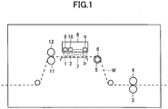
- FIG. 1 is a schematic diagram of a liquid ejection recording type image formation apparatus according to the present embodiment. 1, 2, ... p indicated by dotted lines indicate liquid drop ejection state detection devices in the present embodiment(s).
- a recording medium W is conveyed by a paper feeding conveyance roller 3 coupled to a (not-illustrated) paper feeding motor and a paper feeding conveyance driven roller 4 from a paper feeding part onto a driven roller 6 that is provided with a recording medium feed amount detection encoder 5 for outputting a detection signal depending on movement of a recording medium at a predetermined distance (that will be abbreviated as an "encoder” below) and is drive for conveyance of the recording medium, and then conveyed to a transit plate 7.
- Ink drop ejection onto the recording medium W is conducted by ink-jet heads 9, 10, ... q of an ink-jet head array 8 that is present at a position opposing the transit plate 7.
- the recording medium W conveyed on the transit plate 7 is conveyed by a paper ejection conveyance roller 11 coupled to a (not-illustrated) paper ejection motor and a paper ejection conveyance driven roller 12 and ejected to the exterior of such an ink-jet-type printing apparatus.
- the encoder 5 is installed between the paper feeding conveyance roller 3 and the transit plate 7 but may be installed between the transit plate 7 and the paper ejection conveyance roller 11.
- a liquid ejection recording type “image formation apparatus” means an apparatus that lands an ink onto a paper, thread, fiber, cloth, leather, metal, plastic, glass, wood, or ceramic medium or the like, so as to conduct image formation, and "image formation” means not only applying a meaningful image such as a character or figure onto a medium but also applying a meaningless image such as a pattern onto a medium (simply landing a liquid drop onto a medium).
- an "ink” is not limited to one referred to as an ink and is used as a generic term for all of liquids that are capable of conducting image formation, such as one referred to as a recording liquid, a fixing process liquid, a resin, a liquid, or the like.
- a "paper sheet” is not limited to a paper material, includes an OHP sheet, a cloth, or the like, as described above, means one with an ink drop being attached thereto, and is used as a generic term for those including one referred to as a medium to be recorded, a recording medium, a recording paper, a recording paper sheet, or the like.
- an "image” is not limited to a planar one but also includes an image applied to a stereographically formed one and further an image formed by three-dimensionally shaping a solid per se.
- FIG. 2A, FIG. 2B, and FIG. 2C are schematic diagrams of a liquid drop ejection state detection device according to a first embodiment.
- a liquid drop ejection state detection device 1 in the present embodiment is provided with a light-emitting part 21 and a light-receiving part 22.
- the light-emitting part 21 and the light-receiving part 22 are arranged at positions in such a manner that a light axis L of a light beam 23 is provided in a direction perpendicular to an ink liquid drop 26 ejected from a nozzle (1, 2, ... n) on a head nozzle surface 25 of an ink-jet head 24.
- a light emission driving part 27 sets an amount of light emission.
- a movement mechanism 31 is placed for moving a light-emitting unit 30 with a light-emitting element 28 and a collimator lens 29 mounted thereon.
- FIG. 2B illustrates a view of a case where a light beam is targeted at a first nozzle in a first column, when viewed from an upper side of FIG. 2A
- FIG. 2C illustrates a view of a case where a light beam is targeted at nozzle (number n, sequence 1), when viewed from an upper side of FIG. 2A
- Arrangement is made at a position in such a manner that the light axis L of the light beam 23 is provided at an angle ⁇ 2 (0° ⁇ ⁇ 2 ⁇ 360°) with respect to a direction of conveyance of a recording medium W.
- FIG. 3 is a view of the ink-jet head 24 according to the present embodiment when viewed from an upper side of FIG. 2A .
- Nozzles on the head nozzle surface 25 of the ink-jet head 24 are composed of M nozzle sequences (1, 2, ... M) and each sequence is composed of n nozzles (1, 2,... n).
- the light-emitting part 21 is configured to include the light-emitting element 28 configured to use a semiconductor laser that emits a light beam and the collimator lens 29 that narrows the light beam emitted from the light-emitting element 28 into collimated light to provide the light beam 23 with beam diameters ⁇ 1 and ⁇ 2.
- ⁇ 1 and ⁇ 2 indicate a longitudinal diameter and a transverse diameter in beam diameters.
- the light-emitting element 28 is not limited to a semiconductor laser and it is also possible to be configured to use, for example, a light emitting diode (LED) or the like.
- the light-emitting element 28 and the collimator lens 29 are mounted on the light-emitting unit 30.
- Which of ⁇ 1 and ⁇ 2 is a longitudinal diameter or whether ⁇ 1 ⁇ 2 depends on a condition such as a wavelength and an intensity distribution of a light beam, a separation between respective sequences, a shape and a size of a liquid drop, a kind and a radiation angle of a light-emitting element, a separation between a light-emitting element and a collimator lens, a separation between a light-emitting element and a liquid drop, a separation between a liquid drop and a light-receiving element, a position and a size of a light-receiving element, or a separation between a head and a printing medium.
- a condition such as a wavelength and an intensity distribution of a light beam, a separation between respective sequences, a shape and a size of a liquid drop, a kind and a radiation angle of a light-emitting element, a separation between a light-emitting element and a collimator lens, a separation between
- the movement mechanism 31 moves a light beam emitted from the light-emitting unit 30 to be positioned in such a manner that an ink liquid drop ejected from each nozzle is irradiated therewith.
- the light-receiving part 22 is configured to include a light-receiving element 32 that uses a photodiode or the like.
- the light-receiving part 22 is arranged at a position displaced from the beam diameter ⁇ 2 of the light beam 23 so that a light-receiving surface 33 of the light-receiving element 32 is not provided within the beam diameter ⁇ 2 of the light beam 23.
- the light-receiving part 22 is arranged at a position to be inclined at an angle ⁇ 1 with respect to the light axis L of the light beam 23 and a position to have an angle ⁇ 2 (0 ⁇ ⁇ 2 ⁇ ⁇ 1) with respect to a direction perpendicular to the light axis L.
- ⁇ 11 N and ⁇ 11F indicate an angle of number 1 in sequence 1 with respect to an end face of the light-receiving element 32 near a side of sequence 1 and an angle of number 1 in sequence 1 with respect to an end face of the light-emitting element 32 far from a side of sequence 1.
- ⁇ 1nN and ⁇ 1nF indicate an angle of number n in sequence 1 with respect an end face of the light-receiving element 32 near a side of sequence 1 and an angle of number n in sequence 1 with respect to an end face of the light-emitting element 32 far from a side of sequence 1.
- the ink liquid drop 26 is ejected from each nozzle (number 1 in sequence 1, number 2 in sequence 1, ... number n in sequence 1, number 1 in sequence 2, number 2 in sequence 2, ... number n in sequence 2, ... , number 1 in sequence M, number 2 in sequence M, ... number n in sequence M) on the head nozzle surface 25 of the ink-jet head 24 and the light beam 23 impinges on such an ink liquid drop 26 so that scattered light S is generated.
- the liquid drop ejection state detection device 1 according to the present embodiment, an amount of received light obtained by reaching the light-receiving surface 33 of the light-emitting element 32 in the aforementioned generated scattered light S is light-to-voltage-converted by the light-receiving element 32 and such light-to-voltage-converted output voltage V is measured to obtain data of light-receiving of the scattered light S. Based on such data of light-receiving, a liquid drop ejection state such as presence or absence of ejection of the ink liquid drop 26 or a displacement of ejection of the ink liquid drop 26 is detected.
- FIG. 4 is a diagram illustrating a relationship between an angle ⁇ 1 between the light-receiving element 32 and the light axis L of the light beams 23 and an output voltage V of the light-receiving element 32.
- a transverse axis indicates the angle ⁇ 1 between the light-receiving element 32 and the light axis L and a longitudinal axis indicates the output voltage V of the light-receiving element 32.
- the output voltage V due to the scattered light S has an angular dependence wherein the output voltage V due to the scattered light S is decreased as ⁇ 1 is increased.
- ⁇ 1min is a minimum angle between the light-receiving element 32 and the light axis L on the condition of (1) or (2).
- (1) is a case where the light-receiving element 32 is provided within the beam diameter ⁇ 1 of the light beam 23.
- (2) is a case where the light-receiving element 32 is provided at a position in such a manner that an amount of light received by the light-receiving element 32 is greater than or equal to a threshold value of offset light. Because peripheral light of a light beam is present outside of the beam diameter ⁇ 1 and further light reflected from a recording medium W, the ink-jet head 24, another peripheral component, or the like is provided (that will all be referred to as "offset light” below), offset light is incident on the light-receiving element 32.
- the output voltage V of the light-receiving element 32 is a saturated state of Vmax even on a condition that the ink liquid drop 26 is not ejected, so that it is not possible to detect the scattered light S.
- a value of offset light at this case is a threshold value of offset light.
- an angle ⁇ 1 between the light-receiving element 32 and the light axis L is necessarily ⁇ 1 > ⁇ 1min.
- a downward-sloping curve with respect to an angle ⁇ is illustrated in FIG. 4
- a downward-sloping curve with a waveform may be provided depending on a shape or a size of a liquid drop.
- FIG. 5A and FIG. 5B are diagrams illustrating a relationship between an intensity distribution of a light beam and a position of an ink liquid drop.
- FIG. 5A illustrates a case of a Gaussian distribution
- FIG. 5B illustrates a case of a Gaussian distribution with a waveform.
- An upper figure illustrates an intensity distribution of a light beam, wherein a transverse axis is in a Y-direction and a longitudinal axis is a light intensity.
- a lower figure illustrates a cross section of a light beam.
- FIG. 5A and FIG. 5B are one example of intensity distributions. As illustrated in the figures, a light intensity varies in a Y-direction.
- a light intensity distribution is changed depending on a characteristic or a position of each of a light-emitting element, a collimator lens, and a narrowing member described below, a distance from a light-emitting element or a collimator lens to an ink liquid drop (in a Z-direction), or the like. Accordingly, a position on an intensity distribution is changed depending on a position in a Y-direction with respect to a position of the ink liquid drop 26 ejected from each nozzle and a distance from a light-emitting element or a collimator lens to an ink liquid drop (in a Z-direction) is changed, so that a light intensity on the ink liquid drop 26 ejected from each nozzle is changed.
- An incident angle from an ink liquid drop ejected from nozzle (number 1, sequence 1) to the light-receiving element 32 is in a range of ⁇ 11N - ⁇ 11F and S1 is an amount of received light incident on the light-receiving element 32.
- An incident angle from an ink liquid drop ejected from nozzle (number n, sequence 1) to the light-receiving element 32 is in a range of ⁇ 1nN - ⁇ 1nF and Sn is an amount of received light incident on the light-receiving element 32.
- An incident angle is determined by positions of light incident on an ink liquid drop and a light-receiving surface of a light-receiving element or a shape or a size of a light-receiving surface of a light-receiving element.
- FIG. 7A and FIG. 7B are diagrams illustrating a relationship between an intensity distribution of a light beam and a position of an ink liquid drop.
- FIG. 7A illustrates a case of a Gaussian distribution (nozzle (number n, sequence 1)) and FIG. 7B illustrates a case of a Gaussian distribution with a waveform (nozzle (number n, sequence 1)).
- An upper figure illustrates an intensity distribution of a light beam, wherein a transverse axis is in a Y-direction and a longitudinal axis is a light intensity.
- a lower figure illustrates a cross section of a light beam.
- FIG. 7A and FIG. 7B are one example of intensity distributions.
- a light intensity varies in a Y-direction. Furthermore, a light intensity distribution is changed depending on a characteristic or a position of each of a light-emitting element, a collimator lens, and a narrowing member described below, a distance from a light-emitting element or a collimator lens to an ink liquid drop (in a Z-direction), or the like.
- a position on an intensity distribution is changed depending on a position in a Y-direction with respect to a position of the ink liquid drop 26 ejected from each nozzle and a distance from a light-emitting element or a collimator lens to an ink liquid drop (in a Z-direction) is changed, so that a light intensity on the ink liquid drop 26 ejected from each nozzle is changed.
- the light-emitting unit 30 is moved and thereby a light axis of a light beam is moved to an optimum position to irradiate a liquid drop 26 from each nozzle, so that an amount of a light beam incident on a liquid drop 26 from each nozzle is set at an optimum value.
- a light axis of a light beam is moved to a position of a center of a liquid drop 26 from each nozzle so that an amount of a light beam incident on a liquid drop 26 from each nozzle is increased.
- An incident angle from an ink liquid drop ejected from nozzle (number 1, sequence 1) to the light-receiving element 32 is in a range of ⁇ 11N - ⁇ 11F and S1 is an amount of received light incident on the light-receiving element 32.
- An incident angle from an ink liquid drop ejected from nozzle In to the light-receiving element 32 is in a range of ⁇ 1nN - ⁇ 1nF and Sn is an amount of received light incident on the light-receiving element 32.
- An incident angle is determined by positions of light incident on an ink liquid drop and a light-receiving surface of a light-receiving element or a shape or a size of a light-receiving surface of a light-receiving element.
- a solid line in FIG. 8 indicates a scattered light distribution after moving the light-emitting unit 30 so that a light axis of a light beam is moved to an optimum position to irradiate a liquid drop 26 from each nozzle and setting an amount of light emission of the light-emitting element 28 at an optimum value by the light emission driving part 27 for setting an amount of light emission, and a broken line indicates a scattered light distribution before the setting.
- An amount of light incident on an ink liquid drop ⁇ at a position of each nozzle is determined by an amount of light emission A, an intensity distribution of a light beam at a position for being incident on an ink liquid drop B, a position of an ink liquid drop in an intensity distribution C, a shape of a liquid drop D, a component of a liquid drop E, or the like.
- An amount of light emission A is controllable and it is possible to set an amount of light emission at a position of each nozzle.
- an intensity distribution of a light beam at a position for being incident on an ink liquid drop B is changed depending on diffraction determined by a characteristic of a light-emitting element, characteristics of or a separation among a light-emitting element, a collimator lens, and a narrowing member described below, or a distance from a collimator lens to an ink liquid drop, it is not possible to set an identical intensity distribution at a position of each nozzle.
- a position of an ink liquid drop in an intensity distribution C is determined by a light beam and a position of a nozzle, it is possible to be controlled by moving a horizontal position of a light-emitting element and it is possible to set a position of an ink liquid drop and an intensity distribution of a light beam at optimum positions with respect to a position of each nozzle.
- a shape of a liquid drop D is determined by a characteristic of a nozzle or a driving circuit and a shape (size) of a liquid drop is arbitrarily set at an optimum shape (size) to improve an image quality, it is not possible to set an identical shape of a liquid drop at a position of each nozzle.
- a rate of an amount of scattered light ⁇ at a position of each nozzle is defined as an amount of scattered light / an amount of incident light and is determined by a shape of a liquid drop D, a component of a liquid drop E, a wavelength of a light beam F, or the like. It is possible to control a wavelength of a light beam F by using an identical light beam. However, it is not possible to set a rate of an amount of scattered light ⁇ at an arbitrary value, because it is not possible to set an identical shape of a liquid drop D as mentioned above.
- a rate of incidence on a light-receiving element ⁇ at a position of each nozzle is defined as an amount of scattered light incident on a light-receiving element / an amount of entire scattered light, wherein an amount of scattered light has a high angular dependency and is determined by an amount of light emission A, an intensity distribution of a light beam at a position for being incident on an ink liquid drop B, a position of an ink liquid drop in an intensity distribution C, a shape of a liquid drop D, a component of a liquid drop E, or an angle between a light beam and a light-receiving element G. It is not possible to set a rate of incidence on a light-receiving element ⁇ at an arbitrary value, because it is not possible to provide an identical angle between a light beam and a light-receiving element G or the like.
- an amount of light emission of the light-emitting element 28 is set at an optimum value by the light emission driving part 27 for setting an amount of light emission and the light-emitting unit 30 with the light-emitting element 28 and the collimator lens 28 mounted thereon is moved by the movement mechanism 31 for moving the light-emitting unit 30 to set a position of an ink liquid drop and an intensity distribution of a light beam at optimum positions, so that an amount of light incident on the ink liquid drop 26 ⁇ for each nozzle is changed to set an amount of received light incident on the light-receiving element 32 at an optimum value.
- a position for a maximum amount of light of a light beam is moved to a position of a center of a liquid drop 26 for each nozzle so that an amount of light incident on the ink liquid drop 26 ⁇ for each nozzle is increased.
- FIG. 9A, FIG. 9B, and FIG. 9C are schematic diagrams illustrating a liquid drop ejection state detection device according to a second embodiment.
- a liquid drop ejection state detection device according to the present embodiment is such that a narrowing member 41 for narrowing the light beam 23 emitted from the light-emitting element 28 is placed at a downstream side of the collimator lens 29 in a direction of the light beam 23 in the device according to the first embodiment.
- the light-emitting element 28, the collimator lens 29, and the narrowing member 41 are mounted on the light-emitting unit 30.
- the narrowing member 41 it is possible to provide, for example, an aperture, a slit, or the like.
- the narrowing member 41 is mounted in such a configuration example of the first embodiment so that the light beam 23 emitted from the light-emitting element 28 is narrowed by the narrowing member 41, and thereby, it is possible to reduce beam diameters ⁇ 4 and ⁇ 3 of the light beam 23 ( ⁇ 4 ⁇ ⁇ 2 and ⁇ 3 ⁇ ⁇ 1).
- ⁇ 4 and ⁇ 3 indicate a longitudinal diameter and a transverse diameter in beam diameters.
- FIG. 10 is a diagram illustrating a relationship between angle ⁇ 3 between the light-emitting element 32 and the light axis L of the light beam 23 and an output voltage V of the light-receiving element 32.
- a transverse axis indicates angle ⁇ 3 between the light-emitting element 32 and the light axis L
- a longitudinal axis indicates an output voltage V of the light-receiving element 32.
- An output voltage V due to scattered light S has an angular dependency, wherein an output voltage V due to scattered light S is decreased as the angle ⁇ 3 is increased. Accordingly, an amount of received light due to scattered light S is increased on a condition that the angle ⁇ 3 is in ⁇ 3 ⁇ ⁇ 1, and an output voltage V3 that is light-to-voltage-converted by the light-receiving element 32 is in V1 (an output voltage at ⁇ 1) ⁇ V3 (an output voltage at ⁇ 3).
- the light beam 23 emitted from the light-emitting element 28 is narrowed to suppress a dispersion of a light intensity of the light beam 23 emitted from the light-emitting element 28, a distortion of a wave front thereof, or the like, and thereby, scattered light S generated by irradiating the ink liquid drop 26 with the light beam 23 is also scattered light S with a dispersion of a light intensity, a distortion of a wave front, or the like being suppressed.
- a dispersion of a light intensity of the light beam 23, a distortion of a wave front thereof, or the like is suppressed so that a dispersion of a light intensity, a distortion of a wave front, or the like is also suppressed for scattered light generated by a light beam incident on a liquid drop. Accordingly, a dispersion, a change, or the like, of an amount of received light on the light-receiving element 32 is suppressed, and precision of detection is improved so that detection of a defect of ink ejection is ensured.
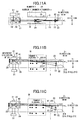
- FIG. 11A, FIG. 11B, and FIG. 11C are schematic diagrams illustrating a liquid drop ejection state detection device according to a third embodiment.
- a liquid drop ejection state detection device according to the present embodiment is such that a light beam in the first or second embodiment is changed from collimated light to convergent light.
- an intensity distribution of a light beam is broadened due to an influence of diffraction as travelling from nozzle (number 1, sequence 1) near a light-emitting element to nozzle (number n, sequence 1) far from the light-emitting element, and a maximum intensity of the beam is reduced.
- an amount of light emission of a light-emitting element is increased and the light-emitting element is moved by light-emitting element movement means, so that a position of an ink liquid drop and an intensity distribution of a light beam are set at optimum positions.
- an amount of incident light is increased from at nozzle (number 1, sequence 1) to at nozzle (number n, sequence 1) more than a case of collimated light, and hence, it is possible to increase an amount of received light.
- an S/N ratio of an amount of received light due to scattered light S to an amount of received light due to noise light N is increased, so that precision of detection is improved and detection of a defect of ink ejection is ensured.
- a rate of convergence is an optimum value, it is possible to provide a comparable amount of received light while an increase of an amount of light emission is suppressed. It is possible to reduce an amount of light emission with respect to a case of collimated light, so that it is possible to reduce a rated output of a light-emitting element and it is possible to reduce a risk level of the light-emitting element. Furthermore, it is also possible to expect an effect of cost reduction.
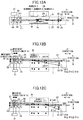
- FIG. 12A, FIG. 12B, and FIG. 12C are schematic diagrams illustrating a liquid drop ejection state detection device according to a fourth embodiment.
- a liquid drop ejection state detection device according to the present embodiment is such that the device according to any of the first to third embodiments is provided with moving means 51 for the light-emitting element 28 in order to change a light beam from collimated light to convergent light.
- a rate of convergence is set in such a manner that an amount of light incident on an ink liquid drop from nozzle (number 1, sequence 1) to nozzle (number n, sequence 1) is an optimum value.
- an amount of incident light for nozzle (number 1, sequence 1) to nozzle (number n, sequence 1) is set at an optimum value, an amount of received light is increased and an S/N ratio of an amount of received light due to scattered light S to an amount of received light due to noise light N is increased, so that precision of detection is improved and detection of a defect of ink ejection is ensured.
- a rate of convergence is an optimum value, it is possible to provide a comparable amount of received light while an increase of an amount of light emission is suppressed. It is possible to reduce an amount of light emission with respect to a case of collimated light, so that it is possible to reduce a rated output of a light-emitting element and it is possible to reduce a risk level of the light-emitting element. Furthermore, it is also possible to expect an effect of cost reduction.
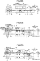
- FIG. 13A, FIG. 13B, and FIG. 13C are schematic diagrams illustrating a liquid drop ejection state detection device according to a fifth embodiment.
- a liquid drop ejection state detection device according to the present embodiment is such that the device according to any of the first to fourth embodiments is provided with a wavelength filter 61 for transmitting only scattered light S with a wavelength identical to a wavelength of the light beam 23 emitted from the light-emitting element 28, at a front side of the light-receiving element 32.
- the wavelength filter 61 is arranged at a position displaced from a beam diameter ⁇ 8 of the light beam 23 so as not to be included in the beam diameter ⁇ 8 of the light beam 23.
- a light-receiving part B it is preferable for a light-receiving part B to be arranged at a position adjacent to a beam diameter ⁇ 8.
- noise light N such as disturbance light is prevented from approaching the light-receiving element 32 and an S/N ratio of an amount of received light due to scattered light S to an amount of received light due to noise light N is increased, so that detection of a defect of ink ejection is ensured.
- the light-emitting element 28 for emitting light beams 23 with different wavelengths and the wavelength filter 61 for transmitting only light with those wavelengths are placed in front of the light-receiving element 32 in a case where a configuration of at least two liquid drop ejection state detection devices for detecting drop ejection states is provided, scattered light from a liquid drop ejection state detection device for detecting an arbitrary ejection state does not transmit through the wavelength filter 61 of a liquid drop ejection state detection device for detecting another ejection state so as not to be incident on the light-receiving element 32 so that detection of a defect of ink ejection is ensured.
- FIG. 14A, FIG. 14B, and FIG. 14C are schematic diagrams illustrating a liquid drop ejection state detection device according to a sixth embodiment.
- a liquid drop ejection state detection device according to the present embodiment is such that the device according to any of the first to fifth embodiments has a light-blocking cylinder 71 and the wavelength filter 61 and the light-receiving element 32 are arranged in one light-blocking cylinder 71.
- noise light N is prevented from approaching between the wavelength filter 61 and the light-receiving element 32 so that it is possible to reduce an amount of received light due to the noise light N.
- the wavelength filter 61 and the light-receiving element 32 are arranged in the one light-blocking cylinder 71 to prevent noise light N such as reflected light of a light beam from a recording medium, a liquid drop ejection head, or the like, or disturbance light, from approaching between the wavelength filter and the light-receiving element, and an amount of received light on the light-receiving element due to scattered light S produced by a light beam being incident on an ink liquid drop at a time of ink ejection to an amount of light on the light-receiving element due to the noise light N is increased, so that an S/N ratio of an amount of received light due to the scattered light S to an amount of received light due to the noise light N is increased and detection of a defect of ink ejection is ensured.
- noise light N such as reflected light of a light beam from a recording medium, a liquid drop ejection head, or the like, or disturbance light
- the light-blocking cylinder 71 it is preferable for the light-blocking cylinder 71 to extend to a side of the light-emitting element 28 with respect to the wavelength filter 61 as long as the light beam 23 is not directly incident on the light-blocking cylinder 71. Thereby, it is possible to further reduce approach of noise light N, so that an S/N ratio of an amount of received light due to the scattered light S to an amount of received light due to the noise light N is further increased and detection of a defect of ink ejection is ensured.
- FIG. 15 is a diagram illustrating an example in such a manner that sets of a plurality of the wavelength filter 61 and the light-receiving element 32 arranged in the one light-blocking cylinder 71 are juxtaposed and arranged on a periphery of the light beam 23 with a beam diameter ⁇ 7.
- FIG. 16 is a diagram illustrating an example in such a manner that a plurality of sets of the wavelength filter 61 and the light-receiving element 32 are juxtaposed and arranged in the one light-blocking cylinder 71 larger than a beam diameter ⁇ 7 of the light beam 23.
- FIG. 17 is a diagram illustrating an example in such a manner that the wavelength filter 61 and the light-receiving element 32 are placed in the one light-blocking cylinder 71.
- FIG. 15 to FIG. 17 illustrate diagrams illustrating configuration examples of a liquid drop ejection state detection device according to a seventh embodiment.
- a liquid drop ejection state detection device according to the present embodiment is such that a plurality of sets of the wavelength filter 61 and the light-receiving element 32 being arranged in the one light-blocking cylinder 71 are arranged in a periphery of the light beam 23 with a beam diameter ⁇ 7.
- FIG. 15 to FIG. 17 illustrate a condition that eight light-blocking cylinders 71 are arranged in a periphery of the light beam 23 with a beam diameter ⁇ 7, wherein shapes of the light-blocking cylinders 71 may be other shapes and the number thereof may also be arbitrary.
- the wavelength filter 61 and the light-receiving element 32 arranged in the one light-blocking cylinder 71 are juxtaposed and arranged on a periphery of the light beam 23 with a beam diameter ⁇ 7 in the liquid drop ejection state detection device according to the present embodiment, it is possible to provide total of amounts of light received by the respective light-receiving elements 32 and thereby increase an amount of received light due to scattered light S used for detection and measurement thereof, even when an amount of light of the light beam 23 emitted from the light-emitting element 28 is small.
- the light-blocking cylinders 71 are juxtaposed and arranged on a periphery of the light beam 23 with a beam diameter ⁇ 7, it is possible to provide an amount of received light due to scattered light S as a total of amount of light received by the respective light-receiving elements 32 and detect an ejection state of the ink liquid drop 26, even when an amount of light of the light beam 23 emitted from the light-emitting element 28 is small.
- FIG. 15 is a case where a plurality of the light-blocking cylinders 71 are juxtaposed and arranged on a periphery of the light beam 23 with a beam diameter ⁇ 7.
- FIG. 16 is a case where a plurality of sets of the wavelength filter 61 and the light-receiving element 32 are juxtaposed and arranged in the one light-blocking cylinder 71 larger than a beam diameter ⁇ 7 of the light beam 23.
- the wavelength filter 61 and the light-receiving element 32 as illustrated in FIG. 16 may have other shapes and the numbers thereof may also be arbitrary.
- a shape of the light-blocking cylinder 71 is also not limited to a circular one and may be another shape.
- FIG. 15 it is also possible to arrange the wavelength filter 61 and the light receiving element 32 that have diameters as illustrated in FIG. 17 and are placed in the one light-blocking cylinder 71, so as to satisfy an area for juxtaposing a plurality of the light blocking cylinders 71 on a periphery of the light beam 23 with a beam diameter ⁇ 7, and arrange a member 81 that does not transmit the light beam 23 to an area with the beam diameter ⁇ 7.
- FIG. 17 illustrates the wavelength filter 61, the light-receiving element 32, and the light-blocking cylinder 71 with a circular shape, as one example, other shapes may be provided.
- the wavelength filter 61 and the light-receiving element 32 are thus placed on a periphery of the light beam 23 with a diameter ⁇ 7 in the liquid drop ejection state detection device according to the present embodiment, it is possible to increase an amount of received light that is received by the light-receiving element 32 even when an amount of light of the light beam 23 emitted from the light-emitting element 28 is small, and hence, it is possible to detect an ejection state of the ink liquid drop 26.
- a light-emitting element is moved by moving means in such a manner that a position with a high energy density of a light beam coincides with a center of an ink liquid drop and an amount of light emission of the light-emitting element is changed, so that an amount of light incident on an ink liquid drop ejected from each nozzle is set at a constant or arbitrary one and thereby it is possible for an amount of scattered light incident on a light-receiving element to be an optimum value, even when an inclination or a change in a nozzle interval of the light-emitting element is caused in a process for detecting an ejection state or when the position with a high energy density of a light beam is not present on a light axis thereof due to a characteristic of the light-emitting element, diffraction, or the like.
- the present embodiment it is possible to set an amount of light incident on an ink liquid drop ejected from each nozzle at a constant or arbitrary one by changing an amount of light emission of a light-emitting element and it is possible to eliminate means for adjusting an inclination angle with respect to a direction intersecting a light axis and a horizontal direction, so that it is possible to reduce a cost because means for adjusting an inclination angle with respect to a direction intersecting a light axis and a horizontal direction are not provided.
- an amount of light incident on an ink liquid drop ejected from each nozzle at a constant or arbitrary one by changing an amount of light emission of a light-emitting element, so that an amount of scattered light from an ink liquid drop is not reduced even when the number of nozzles are large or a nozzle interval is so large that a distance from a light-emitting element to a nozzle is large, and it is possible to detect a defect of ejection of an ink liquid drop accurately.
- a light-emitting element is moved by moving means in such a manner that a position with a high energy density of a light beam coincides with a center of an ink liquid drop and it is possible to provide an identical distance between horizontal positions of a nozzle sequence and a light-receiving element even when a position with a high energy density of a light beam is not present on a light axis thereof due to a characteristic of the light-emitting element, diffraction, or the like, so that an amount of scattered light incident on the light-receiving element is not reduced and hence, it is possible to detect a defect of ejection of an ink liquid drop accurately.
- a light-emitting element is moved by moving means in such a manner that a position with a high energy density of a light beam coincides with a center of an ink liquid drop, so that it is possible to set an amount of light incident on an ink liquid drop ejected from each nozzle at a constant or arbitrary one even when an inclination of a light-emitting element or a change in a nozzle interval is caused.
- ROM Read-Only Memory
- a removable recording medium it is possible to provide a Floppy (registered trade mark) disc, a Compact Disc Read Only Memory (CD-ROM), a Magneto Optical (MO) disc, a Digital Versatile Disc (DVD), a magnetic disc, a semiconductor memory, or the like.
- a Floppy (registered trade mark) disc a Compact Disc Read Only Memory (CD-ROM), a Magneto Optical (MO) disc, a Digital Versatile Disc (DVD), a magnetic disc, a semiconductor memory, or the like.
- CD-ROM Compact Disc Read Only Memory
- MO Magneto Optical
- DVD Digital Versatile Disc
- magnetic disc a magnetic disc
- semiconductor memory or the like.
- a program is installed from a removable recording medium as described above into a computer. Furthermore, wireless transfer from a download site to a computer is executed. Furthermore, a wire transfer through a network to a computer is executed.
- the image formation apparatus or liquid drop ejection state detection device in the present embodiment to not only be executed in a time series in accordance with a processing operation described in the above-mentioned embodiment but also to be configured to execute devices for executing a process with a throughput in parallel or individually according to need.
- At least one illustrative embodiment of the present invention may relate to at least one of a liquid drop ejection state detection device for detecting a defect of ejection of an ink liquid drop and an image formation apparatus.
- An object of at least one illustrative embodiment of the present invention may be to provide a liquid drop ejection state detection device capable of detecting a defect of ejection of a liquid drop accurately, with no mechanical means for adjustment of a position or an inclination of a light axis and no necessity to increase light emission means in a case where a head sequence(s) is/are increased, without increasing an amount of light emission or an amount of offset light, by providing a mechanism capable of moving positions of light emission means and means for adjustment of amount of light emission of light emission means.
- At least one illustrative embodiment of the present invention may be a liquid drop ejection state detection device that has a light-emitting element for emitting a light beam, a light-receiving element arranged at a position displaced from a beam diameter of the light beam, and two or more head sequences that have a plurality of nozzles, wherein scattered light that is generated when the light beam impinges on a liquid drop from each nozzle of each head sequence is received by the light-receiving element and an ejection state of the liquid drop is detected based on an amount of received light that is the received scattered light, wherein the liquid drop ejection state detection device is characterized by having light emitting element movement means for moving the light emitting element in a direction intersecting with a light axis of the light beam and adjustment means for adjusting an amount of light emission of the light-emitting element.
- Illustrative Embodiment (1) is a liquid drop ejection state detection device having a light-emitting element for emitting a light beam, a light-receiving element arranged at a position displaced from a beam diameter of the light beam, and two or more head sequences that have a plurality of nozzles, wherein scattered light that is generated when the light beam impinges on a liquid drop from each nozzle of each head sequence is received by the light-receiving element and an ejection state of the liquid drop is detected based on an amount of received light that is the received scattered light, wherein the liquid drop ejection state detection device is characterized by having light-emitting element movement means for moving the light-emitting element in a direction intersecting with a light axis of the light beam and adjustment means for adjusting an amount of light emission of the light-emitting element.
- Illustrative Embodiment (2) is the liquid drop ejection state detection device as described in Illustrative Embodiment (1), characterized by a narrowing member for narrowing the light beam emitted from the light-emitting element.
- Illustrative Embodiment (3) is the liquid drop ejection state detection device as described in Illustrative Embodiments (1) or (2), characterized in that the light beam is convergent light provided from collimated light.
- Illustrative Embodiment (4) is the liquid drop ejection state detection device as described in any one of Illustrative Embodiments (1) to (3), characterized by having means for movement of the light-emitting element or a collimator lens in such a manner that the light beam is convergent light provided from collimated light.
- Illustrative Embodiment (5) is the liquid drop ejection state detection device as described in any one of Illustrative Embodiments (1) to (4), characterized by having a wavelength filter that transmits only the scattered light with a wavelength identical to a wavelength of the light beam emitted from the light-emitting element, at a front side of the light-receiving element, wherein the light-receiving element receives the scattered light that has been transmitted through the wavelength filter.
- Illustrative Embodiment (6) is the liquid drop ejection state detection device as described in Illustrative Embodiment (1) or (5), characterized in that the wavelength filter and the light-receiving element are provided in at least one light-blocking cylinder.
- Illustrative Embodiment (7) is the liquid drop ejection state detection device as described in any one of Illustrative Embodiments (1) to (6), characterized in that the wavelength filter and the light-receiving element are placed on a periphery of a beam diameter of the light beam.
- Illustrative Embodiment (8) is an image formation apparatus characterized by being provided with the liquid drop ejection state detection device as described in any one of Illustrative Embodiments (1) to (7).
Landscapes
- Engineering & Computer Science (AREA)
- Quality & Reliability (AREA)
- Ink Jet (AREA)
Claims (8)
- Flüssigkeitstropfenausstoßzustand-Erfassungsvorrichtung (1), umfassend:eine Vielzahl von Düsensequenzen, die konfiguriert sind, um eine Vielzahl von Düsen zu haben;ein lichtemittierendes Element (28), das konfiguriert ist, um einen Lichtstrahl (22) entlang einer Lichtachse (L) und der auf einen Flüssigkeitstropfen (26) einfällt, von jeder Düse von jeder Düsensequenz zu emittieren;ein Lichtempfangselement (32), das an einer Position außerhalb eines Strahldurchmessers des Lichtstrahls (22) bereitgestellt ist und konfiguriert ist, um Streulicht von dem Flüssigkeitstropfen (26) zu empfangen und einen Ausstoßzustand des Flüssigkeitstropfens (26) basierend auf einer Menge des Streulichts zu erfassen;ein Einstellteil (27), das konfiguriert ist, um eine Menge von Licht des Lichtstrahls (22) einzustellen, das von dem lichtemittierenden Element (28) emittiert wird, und gekennzeichnet durch:
ein Bewegungsteil für ein lichtemittierendes Element (31), das konfiguriert ist, um das lichtemittierende Element (28) in eine Richtung zu bewegen, die die Lichtachse des Lichtstrahls (22) schneidet, sodass für den Flüssigkeitstropfen (26) von jeder Düse die Lichtachse des Lichtstrahls (22) zu einer Position bewegt wird, an der eine Intensität des Lichtstrahls (22), der auf den Flüssigkeitstropfen (26) einfällt, verglichen mit der Intensität des Lichtstrahls (22), der auf den Flüssigkeitstropfen (26) einfällt, bevor die Lichtachse bewegt wird, erhöht ist, wobei die Position von dem Abstand von dem lichtemittierenden Element (28) zu dem Flüssigkeitstropfen (2) entlang der Lichtachse (L) abhängt. - Flüssigkeitstropfenausstoßzustand-Erfassungsvorrichtung (1) nach Anspruch 1, ferner umfassend:
ein verengendes Element (41), das konfiguriert ist, um den Lichtstrahl (22) zu verengen, der von dem lichtemittierenden Element (21) emittiert wird. - Flüssigkeitstropfenausstoßzustand-Erfassungsvorrichtung (1) nach Anspruch 1 oder 2, wobei der Lichtstrahl (22) ein konvergenter Lichtstrahl ist.
- Flüssigkeitstropfenausstoßzustand-Erfassungsvorrichtung (1) nach Anspruch 3, ferner umfassend:eine Linse (29), die konfiguriert ist, um den Lichtstrahl zu übertragen, der von dem lichtemittierenden Element (21) emittiert wird; undein Bewegungsteil (51), das konfiguriert ist, um mindestens eines des lichtemittierenden Elements (21) und der Linse (2a) zu bewegen, um den konvergenten Lichtstrahl bereitzustellen.
- Flüssigkeitstropfenausstoßzustand-Erfassungsvorrichtung (1) nach einem der Ansprüche 1 bis 4, ferner umfassend:einen Wellenlängenfilter (61), der konfiguriert ist, um das Streulicht mit einer Wellenlänge zu übertragen, die identisch zu einer Wellenlänge des Lichtstrahls (22) ist, der von dem lichtemittierenden Element (21) emittiert wird,wobei das Lichtempfangselement (32) das Streulicht empfängt, das durch den Wellenlängenfilter (61) übertragen wird.
- Flüssigkeitstropfenausstoßzustand-Erfassungsvorrichtung (1) nach Anspruch 5, ferner umfassend:
einen lichtblockierenden Zylinder (71), der konfiguriert ist, um den Wellenlängenfilter (61) und das Lichtempfangselement (31) darin zu enthalten. - Flüssigkeitstropfenausstoßzustand-Erfassungsvorrichtung (1) nach Anspruch 5 oder 6, wobei der Wellenlängenfilter (61) und das Lichtempfangselement (31) an einer Peripherie des Lichtstrahls (22) bereitgestellt sind.
- Bilderzeugungsvorrichtung, umfassend:ein Aufzeichnungsmedium-Beförderungsteil (11), das konfiguriert ist, um ein Aufzeichnungsmedium (W) zu befördern; unddie Flüssigkeitstropfenausstoßzustand-Erfassungsvorrichtung (1) nach einem der Ansprüche 1 bis 7,wobei die Flüssigkeitstropfenausstoßzustand-Erfassungsvorrichtung (1) konfiguriert ist, um einen Ausstoßzustand des Flüssigkeitstropfens (26) auf das Aufzeichnungsmedium (W) zu erfassen.
Applications Claiming Priority (1)
| Application Number | Priority Date | Filing Date | Title |
|---|---|---|---|
| JP2013142557A JP6225517B2 (ja) | 2013-07-08 | 2013-07-08 | 液滴吐出状態検出装置および画像形成装置 |
Publications (3)
| Publication Number | Publication Date |
|---|---|
| EP2837500A2 EP2837500A2 (de) | 2015-02-18 |
| EP2837500A3 EP2837500A3 (de) | 2015-12-23 |
| EP2837500B1 true EP2837500B1 (de) | 2020-04-29 |
Family
ID=51178693
Family Applications (1)
| Application Number | Title | Priority Date | Filing Date |
|---|---|---|---|
| EP14175655.1A Active EP2837500B1 (de) | 2013-07-08 | 2014-07-03 | Vorrichtung zur Detektion des Flüssigtropfenausstoßzustands und Bilderzeugungsvorrichtung |
Country Status (3)
| Country | Link |
|---|---|
| US (1) | US20150009252A1 (de) |
| EP (1) | EP2837500B1 (de) |
| JP (1) | JP6225517B2 (de) |
Families Citing this family (8)
| Publication number | Priority date | Publication date | Assignee | Title |
|---|---|---|---|---|
| JP6264025B2 (ja) * | 2013-12-20 | 2018-01-24 | 株式会社リコー | 液滴吐出状態検出装置、液滴吐出状態検出方法、および、画像形成装置 |
| JP6277837B2 (ja) | 2014-04-11 | 2018-02-14 | 株式会社リコー | 液滴吐出状態検出装置及びこの液滴吐出状態検出装置を備えた画像形成装置 |
| JP6379909B2 (ja) | 2014-09-17 | 2018-08-29 | 株式会社リコー | 画像形成装置、画像形成装置用センサ実装治具、画像形成装置におけるセンサ実装方法 |
| WO2017102016A1 (en) * | 2015-12-17 | 2017-06-22 | Hewlett-Packard Development Company, L.P. | Droplet detection |
| US10518547B2 (en) | 2016-05-30 | 2019-12-31 | Ricoh Company, Ltd. | Liquid discharger and liquid stirring method |
| JP7571437B2 (ja) | 2020-09-16 | 2024-10-23 | 株式会社リコー | シート材を搬送する装置、シート材を加熱する装置、液体を吐出する装置、印刷装置 |
| CN114720424B (zh) * | 2022-03-31 | 2024-05-28 | 北京工业大学 | 注射泵脉动供液导致的ehd喷射不稳定性的检测方法 |
| JP2024058922A (ja) | 2022-10-17 | 2024-04-30 | 株式会社リコー | 画像形成装置、画像形成方法、及び、画像形成プログラム |
Family Cites Families (13)
| Publication number | Priority date | Publication date | Assignee | Title |
|---|---|---|---|---|
| US6419342B1 (en) * | 1999-11-19 | 2002-07-16 | Koninklijke Philips Electronics N.V. | Multi-function monitoring module for a printer |
| JP2005203697A (ja) * | 2004-01-19 | 2005-07-28 | Fuji Photo Film Co Ltd | マルチビーム露光装置 |
| US7483154B2 (en) * | 2005-10-04 | 2009-01-27 | Seiko Epson Corporation | Position detecting device, liquid ejecting apparatus and method of cleaning smear of scale |
| WO2008062651A1 (en) * | 2006-11-22 | 2008-05-29 | Nikon Corporation | Image measuring device |
| JP4931759B2 (ja) * | 2007-10-09 | 2012-05-16 | リコーエレメックス株式会社 | 液吐出不良検出装置、およびインクジェット記録装置 |
| JP5716314B2 (ja) | 2010-08-06 | 2015-05-13 | 株式会社リコー | 液吐出不良検出装置、その調整方法、およびインクジェット記録装置 |
| JP5724320B2 (ja) * | 2010-11-18 | 2015-05-27 | 株式会社リコー | 液滴検出装置およびインクジェット記録装置 |
| JP5652263B2 (ja) * | 2011-03-03 | 2015-01-14 | 株式会社リコー | 画像形成装置および該画像形成装置における液滴吐出検知方法 |
| JP5760627B2 (ja) * | 2011-04-14 | 2015-08-12 | 株式会社リコー | 液吐出不良検出装置およびインクジェット記録装置 |
| JP2013071251A (ja) * | 2011-09-26 | 2013-04-22 | Ricoh Co Ltd | 液滴吐出検知装置及びそれを備えた画像形成装置 |
| JP2013078879A (ja) * | 2011-10-03 | 2013-05-02 | Ricoh Elemex Corp | 液吐出不良検出装置及びインクジェット記録装置 |
| JP2013121663A (ja) * | 2011-12-09 | 2013-06-20 | Ricoh Co Ltd | 液吐出状態検出装置及び画像形成装置 |
| JP5938889B2 (ja) * | 2011-12-16 | 2016-06-22 | 株式会社リコー | 記録装置及び制御方法 |
-
2013
- 2013-07-08 JP JP2013142557A patent/JP6225517B2/ja active Active
-
2014
- 2014-06-27 US US14/318,391 patent/US20150009252A1/en not_active Abandoned
- 2014-07-03 EP EP14175655.1A patent/EP2837500B1/de active Active
Non-Patent Citations (1)
| Title |
|---|
| None * |
Also Published As
| Publication number | Publication date |
|---|---|
| JP6225517B2 (ja) | 2017-11-08 |
| EP2837500A2 (de) | 2015-02-18 |
| EP2837500A3 (de) | 2015-12-23 |
| JP2015013448A (ja) | 2015-01-22 |
| US20150009252A1 (en) | 2015-01-08 |
Similar Documents
| Publication | Publication Date | Title |
|---|---|---|
| EP2837500B1 (de) | Vorrichtung zur Detektion des Flüssigtropfenausstoßzustands und Bilderzeugungsvorrichtung | |
| JP4227395B2 (ja) | 液滴吐出状態判定方法及び装置とインクジェットプリンタ及びそのプログラムと記憶媒体 | |
| EP1907213A1 (de) | Erkennung flüssiger tröpfchen | |
| TWI462840B (zh) | 液滴檢測技術 | |
| JP2015166174A (ja) | 液滴検出装置及びこれを用いたインクジェット記録装置及び液滴検出方法 | |
| US20020186268A1 (en) | Detection of non-operating nozzle by light beam passing through aperture | |
| US7815278B2 (en) | Droplet discharge-condition detecting unit, droplet-discharging device, and inkjet recording device | |
| US9033452B2 (en) | Ejection detection device, ejection detection method, and printing apparatus | |
| JP6277837B2 (ja) | 液滴吐出状態検出装置及びこの液滴吐出状態検出装置を備えた画像形成装置 | |
| US8770705B2 (en) | Droplet discharge detection device and image forming apparatus including droplet discharge detection device | |
| US9347881B2 (en) | Device and method for detecting state of discharged liquid droplet and image forming device incorporating such device | |
| US8870335B2 (en) | Liquid discharge state detection device and image forming apparatus | |
| JP5954026B2 (ja) | 液滴吐出状態検出装置および画像形成装置 | |
| JP4964615B2 (ja) | 液吐出不良検出装置、およびインクジェット記録装置 | |
| JP2022019361A (ja) | 吐出装置 | |
| JP2009113225A (ja) | 液吐出不良検出装置、およびインクジェット記録装置 | |
| JP2009137217A (ja) | インクジェット記録装置、及びその吐出検出用光センサの位置調整方法 | |
| JP2003191453A (ja) | 画像記録装置 | |
| JP5716314B2 (ja) | 液吐出不良検出装置、その調整方法、およびインクジェット記録装置 | |
| CN105939853B (zh) | 喷墨印刷装置 | |
| JP2014117809A (ja) | 液滴吐出状態検出装置及び画像形成装置 | |
| JP4730825B2 (ja) | 液吐出不良検出用光軸とノズル列との位置合わせ方法、液吐出不良検出方法、液吐出不良検出装置、およびインクジェット記録装置 | |
| JP6500395B2 (ja) | 液滴吐出状態検出装置及び画像形成装置 | |
| JP2016087826A (ja) | 液滴吐出状態検出装置、及び画像形成装置 | |
| JP5760627B2 (ja) | 液吐出不良検出装置およびインクジェット記録装置 |
Legal Events
| Date | Code | Title | Description |
|---|---|---|---|
| 17P | Request for examination filed |
Effective date: 20140703 |
|
| AK | Designated contracting states |
Kind code of ref document: A2 Designated state(s): AL AT BE BG CH CY CZ DE DK EE ES FI FR GB GR HR HU IE IS IT LI LT LU LV MC MK MT NL NO PL PT RO RS SE SI SK SM TR |
|
| AX | Request for extension of the european patent |
Extension state: BA ME |
|
| PUAI | Public reference made under article 153(3) epc to a published international application that has entered the european phase |
Free format text: ORIGINAL CODE: 0009012 |
|
| PUAL | Search report despatched |
Free format text: ORIGINAL CODE: 0009013 |
|
| AK | Designated contracting states |
Kind code of ref document: A3 Designated state(s): AL AT BE BG CH CY CZ DE DK EE ES FI FR GB GR HR HU IE IS IT LI LT LU LV MC MK MT NL NO PL PT RO RS SE SI SK SM TR |
|
| AX | Request for extension of the european patent |
Extension state: BA ME |
|
| RIC1 | Information provided on ipc code assigned before grant |
Ipc: B41J 2/165 20060101ALI20151116BHEP Ipc: B41J 2/21 20060101AFI20151116BHEP |
|
| STAA | Information on the status of an ep patent application or granted ep patent |
Free format text: STATUS: EXAMINATION IS IN PROGRESS |
|
| 17Q | First examination report despatched |
Effective date: 20181217 |
|
| GRAP | Despatch of communication of intention to grant a patent |
Free format text: ORIGINAL CODE: EPIDOSNIGR1 |
|
| STAA | Information on the status of an ep patent application or granted ep patent |
Free format text: STATUS: GRANT OF PATENT IS INTENDED |
|
| INTG | Intention to grant announced |
Effective date: 20200124 |
|
| GRAS | Grant fee paid |
Free format text: ORIGINAL CODE: EPIDOSNIGR3 |
|
| GRAA | (expected) grant |
Free format text: ORIGINAL CODE: 0009210 |
|
| STAA | Information on the status of an ep patent application or granted ep patent |
Free format text: STATUS: THE PATENT HAS BEEN GRANTED |
|
| RIN1 | Information on inventor provided before grant (corrected) |
Inventor name: MIKI, HIDEHARU Inventor name: ANDOH, HIROSHI Inventor name: KAWAMICHI, GENICHIRO Inventor name: MORINAGA, SHIGERU Inventor name: TOKUYAMA, KOHJI |
|
| AK | Designated contracting states |
Kind code of ref document: B1 Designated state(s): AL AT BE BG CH CY CZ DE DK EE ES FI FR GB GR HR HU IE IS IT LI LT LU LV MC MK MT NL NO PL PT RO RS SE SI SK SM TR |
|
| REG | Reference to a national code |
Ref country code: GB Ref legal event code: FG4D |
|
| REG | Reference to a national code |
Ref country code: CH Ref legal event code: EP |
|
| REG | Reference to a national code |
Ref country code: AT Ref legal event code: REF Ref document number: 1262701 Country of ref document: AT Kind code of ref document: T Effective date: 20200515 |
|
| REG | Reference to a national code |
Ref country code: DE Ref legal event code: R096 Ref document number: 602014064411 Country of ref document: DE |
|
| REG | Reference to a national code |
Ref country code: IE Ref legal event code: FG4D |
|
| REG | Reference to a national code |
Ref country code: NL Ref legal event code: FP |
|
| REG | Reference to a national code |
Ref country code: LT Ref legal event code: MG4D |
|
| PG25 | Lapsed in a contracting state [announced via postgrant information from national office to epo] |
Ref country code: PT Free format text: LAPSE BECAUSE OF FAILURE TO SUBMIT A TRANSLATION OF THE DESCRIPTION OR TO PAY THE FEE WITHIN THE PRESCRIBED TIME-LIMIT Effective date: 20200831 Ref country code: IS Free format text: LAPSE BECAUSE OF FAILURE TO SUBMIT A TRANSLATION OF THE DESCRIPTION OR TO PAY THE FEE WITHIN THE PRESCRIBED TIME-LIMIT Effective date: 20200829 Ref country code: GR Free format text: LAPSE BECAUSE OF FAILURE TO SUBMIT A TRANSLATION OF THE DESCRIPTION OR TO PAY THE FEE WITHIN THE PRESCRIBED TIME-LIMIT Effective date: 20200730 Ref country code: FI Free format text: LAPSE BECAUSE OF FAILURE TO SUBMIT A TRANSLATION OF THE DESCRIPTION OR TO PAY THE FEE WITHIN THE PRESCRIBED TIME-LIMIT Effective date: 20200429 Ref country code: NO Free format text: LAPSE BECAUSE OF FAILURE TO SUBMIT A TRANSLATION OF THE DESCRIPTION OR TO PAY THE FEE WITHIN THE PRESCRIBED TIME-LIMIT Effective date: 20200729 Ref country code: SE Free format text: LAPSE BECAUSE OF FAILURE TO SUBMIT A TRANSLATION OF THE DESCRIPTION OR TO PAY THE FEE WITHIN THE PRESCRIBED TIME-LIMIT Effective date: 20200429 Ref country code: LT Free format text: LAPSE BECAUSE OF FAILURE TO SUBMIT A TRANSLATION OF THE DESCRIPTION OR TO PAY THE FEE WITHIN THE PRESCRIBED TIME-LIMIT Effective date: 20200429 |
|
| REG | Reference to a national code |
Ref country code: AT Ref legal event code: MK05 Ref document number: 1262701 Country of ref document: AT Kind code of ref document: T Effective date: 20200429 |
|
| PG25 | Lapsed in a contracting state [announced via postgrant information from national office to epo] |
Ref country code: BG Free format text: LAPSE BECAUSE OF FAILURE TO SUBMIT A TRANSLATION OF THE DESCRIPTION OR TO PAY THE FEE WITHIN THE PRESCRIBED TIME-LIMIT Effective date: 20200729 Ref country code: RS Free format text: LAPSE BECAUSE OF FAILURE TO SUBMIT A TRANSLATION OF THE DESCRIPTION OR TO PAY THE FEE WITHIN THE PRESCRIBED TIME-LIMIT Effective date: 20200429 Ref country code: LV Free format text: LAPSE BECAUSE OF FAILURE TO SUBMIT A TRANSLATION OF THE DESCRIPTION OR TO PAY THE FEE WITHIN THE PRESCRIBED TIME-LIMIT Effective date: 20200429 Ref country code: HR Free format text: LAPSE BECAUSE OF FAILURE TO SUBMIT A TRANSLATION OF THE DESCRIPTION OR TO PAY THE FEE WITHIN THE PRESCRIBED TIME-LIMIT Effective date: 20200429 |
|
| PG25 | Lapsed in a contracting state [announced via postgrant information from national office to epo] |
Ref country code: AL Free format text: LAPSE BECAUSE OF FAILURE TO SUBMIT A TRANSLATION OF THE DESCRIPTION OR TO PAY THE FEE WITHIN THE PRESCRIBED TIME-LIMIT Effective date: 20200429 |
|
| PG25 | Lapsed in a contracting state [announced via postgrant information from national office to epo] |
Ref country code: EE Free format text: LAPSE BECAUSE OF FAILURE TO SUBMIT A TRANSLATION OF THE DESCRIPTION OR TO PAY THE FEE WITHIN THE PRESCRIBED TIME-LIMIT Effective date: 20200429 Ref country code: AT Free format text: LAPSE BECAUSE OF FAILURE TO SUBMIT A TRANSLATION OF THE DESCRIPTION OR TO PAY THE FEE WITHIN THE PRESCRIBED TIME-LIMIT Effective date: 20200429 Ref country code: SM Free format text: LAPSE BECAUSE OF FAILURE TO SUBMIT A TRANSLATION OF THE DESCRIPTION OR TO PAY THE FEE WITHIN THE PRESCRIBED TIME-LIMIT Effective date: 20200429 Ref country code: IT Free format text: LAPSE BECAUSE OF FAILURE TO SUBMIT A TRANSLATION OF THE DESCRIPTION OR TO PAY THE FEE WITHIN THE PRESCRIBED TIME-LIMIT Effective date: 20200429 Ref country code: DK Free format text: LAPSE BECAUSE OF FAILURE TO SUBMIT A TRANSLATION OF THE DESCRIPTION OR TO PAY THE FEE WITHIN THE PRESCRIBED TIME-LIMIT Effective date: 20200429 Ref country code: CZ Free format text: LAPSE BECAUSE OF FAILURE TO SUBMIT A TRANSLATION OF THE DESCRIPTION OR TO PAY THE FEE WITHIN THE PRESCRIBED TIME-LIMIT Effective date: 20200429 Ref country code: RO Free format text: LAPSE BECAUSE OF FAILURE TO SUBMIT A TRANSLATION OF THE DESCRIPTION OR TO PAY THE FEE WITHIN THE PRESCRIBED TIME-LIMIT Effective date: 20200429 Ref country code: ES Free format text: LAPSE BECAUSE OF FAILURE TO SUBMIT A TRANSLATION OF THE DESCRIPTION OR TO PAY THE FEE WITHIN THE PRESCRIBED TIME-LIMIT Effective date: 20200429 |
|
| REG | Reference to a national code |
Ref country code: DE Ref legal event code: R097 Ref document number: 602014064411 Country of ref document: DE |
|
| REG | Reference to a national code |
Ref country code: DE Ref legal event code: R119 Ref document number: 602014064411 Country of ref document: DE |
|
| PG25 | Lapsed in a contracting state [announced via postgrant information from national office to epo] |
Ref country code: MC Free format text: LAPSE BECAUSE OF FAILURE TO SUBMIT A TRANSLATION OF THE DESCRIPTION OR TO PAY THE FEE WITHIN THE PRESCRIBED TIME-LIMIT Effective date: 20200429 Ref country code: PL Free format text: LAPSE BECAUSE OF FAILURE TO SUBMIT A TRANSLATION OF THE DESCRIPTION OR TO PAY THE FEE WITHIN THE PRESCRIBED TIME-LIMIT Effective date: 20200429 Ref country code: SK Free format text: LAPSE BECAUSE OF FAILURE TO SUBMIT A TRANSLATION OF THE DESCRIPTION OR TO PAY THE FEE WITHIN THE PRESCRIBED TIME-LIMIT Effective date: 20200429 |
|
| REG | Reference to a national code |
Ref country code: CH Ref legal event code: PL |
|
| REG | Reference to a national code |
Ref country code: NL Ref legal event code: MM Effective date: 20200801 |
|
| PLBE | No opposition filed within time limit |
Free format text: ORIGINAL CODE: 0009261 |
|
| STAA | Information on the status of an ep patent application or granted ep patent |
Free format text: STATUS: NO OPPOSITION FILED WITHIN TIME LIMIT |
|
| GBPC | Gb: european patent ceased through non-payment of renewal fee |
Effective date: 20200729 |
|
| 26N | No opposition filed |
Effective date: 20210201 |
|
| REG | Reference to a national code |
Ref country code: BE Ref legal event code: MM Effective date: 20200731 |
|
| PG25 | Lapsed in a contracting state [announced via postgrant information from national office to epo] |
Ref country code: LU Free format text: LAPSE BECAUSE OF NON-PAYMENT OF DUE FEES Effective date: 20200703 Ref country code: NL Free format text: LAPSE BECAUSE OF NON-PAYMENT OF DUE FEES Effective date: 20200801 Ref country code: FR Free format text: LAPSE BECAUSE OF NON-PAYMENT OF DUE FEES Effective date: 20200731 Ref country code: CH Free format text: LAPSE BECAUSE OF NON-PAYMENT OF DUE FEES Effective date: 20200731 Ref country code: GB Free format text: LAPSE BECAUSE OF NON-PAYMENT OF DUE FEES Effective date: 20200729 Ref country code: LI Free format text: LAPSE BECAUSE OF NON-PAYMENT OF DUE FEES Effective date: 20200731 Ref country code: IE Free format text: LAPSE BECAUSE OF NON-PAYMENT OF DUE FEES Effective date: 20200703 |
|
| PG25 | Lapsed in a contracting state [announced via postgrant information from national office to epo] |
Ref country code: BE Free format text: LAPSE BECAUSE OF NON-PAYMENT OF DUE FEES Effective date: 20200731 Ref country code: DE Free format text: LAPSE BECAUSE OF NON-PAYMENT OF DUE FEES Effective date: 20210202 Ref country code: SI Free format text: LAPSE BECAUSE OF FAILURE TO SUBMIT A TRANSLATION OF THE DESCRIPTION OR TO PAY THE FEE WITHIN THE PRESCRIBED TIME-LIMIT Effective date: 20200429 |
|
| PG25 | Lapsed in a contracting state [announced via postgrant information from national office to epo] |
Ref country code: TR Free format text: LAPSE BECAUSE OF FAILURE TO SUBMIT A TRANSLATION OF THE DESCRIPTION OR TO PAY THE FEE WITHIN THE PRESCRIBED TIME-LIMIT Effective date: 20200429 Ref country code: MT Free format text: LAPSE BECAUSE OF FAILURE TO SUBMIT A TRANSLATION OF THE DESCRIPTION OR TO PAY THE FEE WITHIN THE PRESCRIBED TIME-LIMIT Effective date: 20200429 Ref country code: CY Free format text: LAPSE BECAUSE OF FAILURE TO SUBMIT A TRANSLATION OF THE DESCRIPTION OR TO PAY THE FEE WITHIN THE PRESCRIBED TIME-LIMIT Effective date: 20200429 |
|
| PG25 | Lapsed in a contracting state [announced via postgrant information from national office to epo] |
Ref country code: MK Free format text: LAPSE BECAUSE OF FAILURE TO SUBMIT A TRANSLATION OF THE DESCRIPTION OR TO PAY THE FEE WITHIN THE PRESCRIBED TIME-LIMIT Effective date: 20200429 |