EP2835489B1 - Jalousierbarer Rollladenpanzer mit schwenkbaren Stäben - Google Patents
Jalousierbarer Rollladenpanzer mit schwenkbaren Stäben Download PDFInfo
- Publication number
- EP2835489B1 EP2835489B1 EP14180428.6A EP14180428A EP2835489B1 EP 2835489 B1 EP2835489 B1 EP 2835489B1 EP 14180428 A EP14180428 A EP 14180428A EP 2835489 B1 EP2835489 B1 EP 2835489B1
- Authority
- EP
- European Patent Office
- Prior art keywords
- roller shutter
- shutter according
- slats
- guide
- magnets
- Prior art date
- Legal status (The legal status is an assumption and is not a legal conclusion. Google has not performed a legal analysis and makes no representation as to the accuracy of the status listed.)
- Active
Links
Images



Classifications
-
- E—FIXED CONSTRUCTIONS
- E06—DOORS, WINDOWS, SHUTTERS, OR ROLLER BLINDS IN GENERAL; LADDERS
- E06B—FIXED OR MOVABLE CLOSURES FOR OPENINGS IN BUILDINGS, VEHICLES, FENCES OR LIKE ENCLOSURES IN GENERAL, e.g. DOORS, WINDOWS, BLINDS, GATES
- E06B9/00—Screening or protective devices for wall or similar openings, with or without operating or securing mechanisms; Closures of similar construction
- E06B9/02—Shutters, movable grilles, or other safety closing devices, e.g. against burglary
- E06B9/08—Roll-type closures
- E06B9/11—Roller shutters
- E06B9/15—Roller shutters with closing members formed of slats or the like
-
- E—FIXED CONSTRUCTIONS
- E06—DOORS, WINDOWS, SHUTTERS, OR ROLLER BLINDS IN GENERAL; LADDERS
- E06B—FIXED OR MOVABLE CLOSURES FOR OPENINGS IN BUILDINGS, VEHICLES, FENCES OR LIKE ENCLOSURES IN GENERAL, e.g. DOORS, WINDOWS, BLINDS, GATES
- E06B9/00—Screening or protective devices for wall or similar openings, with or without operating or securing mechanisms; Closures of similar construction
- E06B9/24—Screens or other constructions affording protection against light, especially against sunshine; Similar screens for privacy or appearance; Slat blinds
- E06B9/26—Lamellar or like blinds, e.g. venetian blinds
- E06B9/28—Lamellar or like blinds, e.g. venetian blinds with horizontal lamellae, e.g. non-liftable
- E06B9/34—Lamellar or like blinds, e.g. venetian blinds with horizontal lamellae, e.g. non-liftable roller-type; Roller shutters with adjustable lamellae
-
- E—FIXED CONSTRUCTIONS
- E06—DOORS, WINDOWS, SHUTTERS, OR ROLLER BLINDS IN GENERAL; LADDERS
- E06B—FIXED OR MOVABLE CLOSURES FOR OPENINGS IN BUILDINGS, VEHICLES, FENCES OR LIKE ENCLOSURES IN GENERAL, e.g. DOORS, WINDOWS, BLINDS, GATES
- E06B9/00—Screening or protective devices for wall or similar openings, with or without operating or securing mechanisms; Closures of similar construction
- E06B9/56—Operating, guiding or securing devices or arrangements for roll-type closures; Spring drums; Tape drums; Counterweighting arrangements therefor
- E06B9/58—Guiding devices
-
- E—FIXED CONSTRUCTIONS
- E06—DOORS, WINDOWS, SHUTTERS, OR ROLLER BLINDS IN GENERAL; LADDERS
- E06B—FIXED OR MOVABLE CLOSURES FOR OPENINGS IN BUILDINGS, VEHICLES, FENCES OR LIKE ENCLOSURES IN GENERAL, e.g. DOORS, WINDOWS, BLINDS, GATES
- E06B9/00—Screening or protective devices for wall or similar openings, with or without operating or securing mechanisms; Closures of similar construction
- E06B9/02—Shutters, movable grilles, or other safety closing devices, e.g. against burglary
- E06B9/08—Roll-type closures
- E06B9/11—Roller shutters
- E06B9/15—Roller shutters with closing members formed of slats or the like
- E06B2009/1577—Slat end pieces used for guiding shutter
- E06B2009/1583—Slat end pieces used for guiding shutter inserted in slat cavity
Definitions
- the invention relates to a roller blind roller blind with a curtain of a plurality of horizontally arranged and non-interlocking rods, the rods having at their ends frontally arranged guide elements and are connected thereto via a pivot axis in the lower region of the rods, wherein the guide elements in vertical guide profiles are guided and have actuators that allow pivotal movement of the individual rods.
- a generic roller shutter with all features of the preamble of claim 1 is known from EP 0 056 650 B1 known.
- the present invention has the object, an initially described and previously explained in more detail louvered shutters and further educate to achieve with little effort and without Matternmaschine an optimized swinging and so to create a louverable and "light-directing" shutters.
- the first magnets are provided as actuators, which arranged by outside of the roller shutter other magnets by suitable tightening and / or repelling for opening and possibly closing the rods movable are.
- the guide elements are two magnets that tighten, or repel each other by opposite polarity magnets.
- magnets in particular also magnet coils or magnet coil modules, ie electromagnets, should be included, which can be controlled centrally.
- magnets serve the leadership of the bar ends at a Schrägrolladen.
- each guide element has a pivoting element connected to the associated rod end and a locking element located vertically in the guide profile.
- These elements together with the guide profiles, which each lead a carriage on the right and left, form the core of the invention.
- the pivoting element locked in pivoted position with the locking element.
- the guide elements are made of a plastic material components. In it are all mechanical components for a perfect function of the shutter blinds. The axis is most important for the pivoting of the shutter and must be stably and securely connected to the locking piece. It is preferred to use a reinforced axle, which is inserted deeper into the locking element and glued there or firmly connected in another way.
- a further preferred embodiment of the invention provides that the opening angle between the pivot element and the locking element is variable.
- an adjustable stop element is provided on the pivoting element and / or on the locking element.
- the opening angle between the pivot element and the locking element is fixed.
- each guide element has a spreading element for holding the pivoting element in its open position.
- This is preferably a spring which extends around the pivot axis and whose legs are fixedly connected to the pivoting element or the locking element. The springs at both ends of each rod thus ensure reliably that the curtain does not swivel back in the open position even under the influence of wind.
- the pivot axis passes through the locking element and at its end has a non-rotatably connected lever, which lies in pivoted position in the plane of the curtain.
- a non-rotatably connected lever which lies in pivoted position in the plane of the curtain.
- For pivoting is preferably at least one magnet in or arranged on the lever.
- the complete lever is designed as a magnet.
- the further magnets for actuating the magnets on the pivoting or locking element on a movable carriage.
- the further magnets are formed by a plurality of electromagnets arranged in or on the guide profile, which can be activated or reversed by a suitable control for opening any bars or bar areas.
- a structurally particularly elegant design is achieved when, instead of a slide or a plurality of magnets distributed in the guide profiles arranged in each case a magnet or solenoid module is arranged in the two inlet funnels.
- a magnet or solenoid module is arranged in the two inlet funnels.
- Such a design is quite sufficient to achieve the same effect:
- the fact that when extending the shutter all rods pass through the inlet funnel and thus the magnets located there, can with an 'intelligent' control, which also saves space in one of Inlet funnel can be arranged, the information about the to be opened when descending rods to the two magnets are passed.
- the inlet funnel without control in this case only needs to have a module which executes the commands of the controller by means of the local magnet.
- the control unit is sealed in the inlet funnel, but can of course be installed elsewhere.
- the controller can also be expanded - possibly modulo attachable - other modules, such as radio modules for bidirectional communication.
- each carriage each has a magnet for opening and a magnet for closing individual rods of the roller shutter.
- repelling magnets exerts a force on the rotatably connected to the rod lever to overcome the locking force between the locking element and pivot member and so pivots the respective rod in its open position.
- a method of sliding in the opposite direction can be attracted by another magnet, the magnet at the upper end of the pivot member. In this case, the magnetic force must be greater than the spring force of the expansion element and the locking force between the locking element and the pivot element in order to achieve a reliable locking of both elements (at each end of the rod).
- each connecting element has a slot for releasing or closing the respectively immediately adjacent bars. If the curtain (with all the bars in closed position) has moved completely down, the upper webs of the bars reach into the pocket of the respectively overlying bar, so that the curtain is positively closed like a conventional roller shutter. When the bars are raised again, the oblong holes ensure that an air gap is created between the adjacent bars so that a reopening of individual bars or bar areas is possible.
- the guide elements are arranged completely within the guide profiles.
- the shutter according to the invention looks from the inside and outside - like a conventional roller shutter.
- the curtain can be wound on a winding shaft.
- the optionally still open rods are closed positively guided by suitable guide or actuating means when leaving the vertical guide profile, so that a normal roller shutter function is possible.
- the roller shutter armor can therefore also be moved (wound up) despite open bars.
- the rods adapt to the winding behavior. It is conceivable to drive the entire system with a drive unit or with two separate drives. Also, the roller shutter according to the invention is therefore a normal, winding roller shutter, in which nevertheless the rods can steer the light into the room by pivoting.
- roller shutter whose bars directs the daylight into rooms.
- Conceivable is a highly reflective coating of the rods, so that the light is directed more effectively into the room.
- the roller shutter armor according to the invention is particularly suitable for rooms that achieved little or no natural light.
- the roller shutter in any position, whether half shut down or completely down, by the carriage, the individual pivotally mounted roller shutter bars pivot in an open or closed position.
- the roller shutter can be mounted depending on the construction project as a left or right scooter. Due to the magnetism in the guide elements, the bars, no matter which position the curtain has to be brought into a closed or in an open position. The advantage of this is that you can use a "normal" shutter as it were, to darken a room or to fulfill the function of the light control to produce an indirect light.
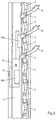
- FIG. 1 an inventive curtain 1 a jalousable roller shutter is shown in perspective in the upper part of the curtain 1 partially swung rods 2.
- the opened (upper) region of the curtain 1 is denoted by the reference symbol 1A and the closed (lower) region of the curtain 1 by the reference symbol 1B. It can be seen that the opening angle is about 60 °, so that the reflection of the daylight on the bars 2, an indirect illumination of the space behind it takes place.
- each guide element 4 has a pivoting element 6 connected to the respective end of the rod 2 and a locking element 7 located vertically in the guide profile 5, in particular the enlarged illustration in FIG Fig. 3 can be seen.
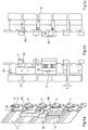
- Fig. 2b shows an alternative embodiment.
- a mechanical guide roller 17 ensures a positively controlled closing of opened individual bars of the curtain when raising the shutter.
- Below the roller shutter box 16 is in Fig. 2b an inlet funnel 19 is shown, in which a magnetic module M3 is arranged such that its activation causes an opening of the passing roller shutter bar 2, as will be described in detail below.
- An only indicated control unit 20 ensures the corresponding implementation of the operating commands in a control of the magnets M3.
- the right Fig. 2b with the Fig. 2a match.
- Fig. 4 represent. There shows Fig. 4a - For the embodiment with carriage - the end portion of the curtain 1 analogous to Fig. 3 in perspective view and the figures Fig. 4b and 4c in two side views, for better explanation of the interaction of the actuators all bars 2 are shown closed, even if in this position, the upper two bars 2 would have to be open.
- FIG. 5 Before discussing the interaction of all structural parts, the construction of a single guide element 4 based on the perspective view of the same in FIG Fig. 5 to be introduced. It can be seen first, the pivoting element 6, which is attached to the front end of the rod 2. The pivoting element 6 is arranged pivotably on the locking element 7 via the pivot axis 3, wherein a spring 8, of which only the free leg connected to the pivoting element 6 can be seen, is guided around the pivot axis 3 as a spiral spring. The other free leg of the spring 8 is (in Fig. 5 not visible) in a corresponding manner connected to the locking element 7. In this way, it is ensured that the curtain 1 does not swivel in the open position even under the influence of wind.
- the pivot axis 3 is guided through the locking element 7 and at its end a rotatably mounted lever 9 has.
- For magnetic drive serve two magnets M1 and M2, of which the first is arranged at the free upper end of the pivot member 6 and the second at the lower end of the lever 9.
- On a carriage 10 two more magnets M3 and M4 are attached, as shown in the Figures 3 and 4a evident.
- the carriage 10 is vertically displaceable by means of a guide 11 along a guide rail 12 arranged in the interior of the guide profile 5.
- the magnets M1 and M3 repel each other, so that when moving the carriage 10 down to open the with the Swivel elements 6 connected rods 2 takes place.
- Fig. 4a such as Fig. 5 is also clearly the articulated connection between the respective adjacent guide elements 4 to recognize.
- Fig. 5 is shown above the guide member 4 shown in phantom, the connecting element 13 of the guide element (not shown) arranged above it.
- the bars 2 of the curtain 1 are thus, except for the mutual entanglement, as in "normal" blinds hinged together.
- the curtain 1 can be wound in a known manner on a winding shaft 15 in a roller shutter box 16, as in the Fig. 2a and 2b shown.
- a mechanical guide roller 17 ensures that the curtain 1 can be wound even in the "open” state by after exiting the vertical guide profile 5 by acting on the pivoted lever 9 a positively guided closing of the rods 2 takes place before they are wound up, so that a normal roller shutter function is possible.
- the connecting element 13 is rotatably arranged not only in the region of the pivot axis 3, in its lower region, the connecting element 13 has an axis 18 which engages in a corresponding recess of the locking element (not shown) arranged thereunder and with this is rotatably connected.
Landscapes
- Engineering & Computer Science (AREA)
- Structural Engineering (AREA)
- Architecture (AREA)
- Civil Engineering (AREA)
- Operating, Guiding And Securing Of Roll- Type Closing Members (AREA)
- Blinds (AREA)
Description
- Die Erfindung betrifft einen jalousierbaren Rollladenpanzer mit einem Behang aus einer Mehrzahl horizontal angeordneter und nicht miteinander verhakter Stäbe, wobei die Stäbe an ihren Enden stirnseitig angeordnete Führungselemente aufweisen und mit diesen über eine Schwenkachse im unteren Bereich der Stäbe verbunden sind, wobei die Führungselemente in vertikalen Führungsprofilen geführt sind und Betätigungselemente aufweisen, welche eine Schwenkbewegung der einzelnen Stäbe erlauben.
- Die Idee, Rollläden mit zu Öffnungszwecken um eine horizontale Achse verschwenkbaren Stäben zu versehen, ist seit langem bekannt. Hierzu sind diverse technische Lösungen vorgestellt worden (
DE 29 29 675 A1 ). - Es sind Systeme bekannt, die mit einem Schienensystem das Verschwenken der Rollladenstäbe auslösen (
DE 94 03 992 U1 ). Die Stäbe sind an der Schiene befestigt und diese Schiene lässt sich durch ein Zahnriemenprinzip auf und ab fahren und wodurch die Stäbe jeweils in eine geschlossene oder geöffnete Stellung gebracht werden. Eine andere mechanische Verstelleinrichtung eines jalousierbaren Rollladens ist aus derDE 198 42 502 A1 bekannt. Darüber hinaus sind auch Lösungen mit auf die Stäbe wirkenden Zugbändern bekannt (DE 20 2013 100 148 U1 ). DieWO 2012/065917 A1 beschreibt einen Rolladen mit rotatorisch verstellbaren Stäben, welche jeweils mittels einem Antriebsritzen von einer Zahnstange verstellt werden. All diese Lösungen sind konstruktiv sehr aufwendig. - Bei vielen Entwicklungen ist ein individuelles Verstellen nicht möglich. Oft gibt es nur die Variante zwischen offen und zu oder sogar nur offen (
DE 10 2005 037 775 B4 ). Es gibt hierbei also nur eine Stellung bei der das Licht gelenkt wird. Es ist keine Entwicklung bekannt, bei der das Verstellen der Lamellen zum Lichtlenken in jeder Position des Panzers möglich ist. - Ein gattungsgemäßer Rolladenpanzer mit allen Merkmalen des Oberbegriffs von Anspruch 1 ist aus der
EP 0 056 650 B1 bekannt. - Die aktuelle Marktsituation verlangt nach einer Möglichkeit, die einfallenden Sonnenstrahlen und damit auch die Sonnenenergie besser zu nutzen. Dabei darf aber nicht auf die bekannten Vorteile des Rollladens, beispielsweise in den Nachtstunden, verzichtet werden.
- Davon ausgehend, liegt der vorliegenden Erfindung die Aufgabe zugrunde, einen eingangs beschriebenen und zuvor näher erläuterten jalousierbaren Rollladen so auszugestalten und weiterzubilden, um mit geringem Aufwand und ohne Übertechnisierung ein optimiertes Aufschwenken zu erreichen und so einen jalousierbaren und "Licht lenkenden" Rollladen zu schaffen.
- Gelöst wurde diese Aufgabe bei einem jalousierbaren Rollladen mit allen Merkmalen des Oberbegriffs von Anspruch 1 dadurch, dass als Betätigungselemente erste Magnete vorgesehen sind, welche von außerhalb des Rollladenpanzers angeordneten weiteren Magneten durch geeignetes Anziehen und/oder Abstoßen zum Öffnen und ggf. Schließen der Stäbe bewegbar sind. In den Führungselementen stecken zwei Magnete, die sich anziehen, bzw. durch gegenpolige Magnete abstoßen. Dadurch wird der Rollladen im gewünschten Bereich in die Licht leitende Öffnungsposition geschwenkt. Der Lichteinfallswinkel beträgt dabei ca. 60°. Die Vorteile der Erfindung liegen darin, dass die Stäbe von unten schwenken, so kann der Stab durch die Stabform das Licht indirekt in den Raum lenken.
- Wenn von "Magneten" die Rede ist, sollen hier insbesondere auch Magnetspulen bzw. Magnetspulenmodule, also Elektromagnete, umfasst sein, welche sich zentral ansteuern lassen.
- Die Verwendung von Magneten ist für sich bereits durch die
DE 40 20 244 A1 bekannt. Dort dienen die Magnete jedoch der Führung der Stabenden bei einem Schrägrolladen. - Eine weitere Lehre der Erfindung sieht vor, dass jedes Führungselement ein mit dem zugehörigen Stabende verbundenes Schwenkelement und ein senkrecht im Führungsprofil befindliches Arretierelement aufweist. Diese Elemente bilden gemeinsam mit den Führungsprofilen, welche jeweils rechts und links einen Schlitten führen, das Kernstück der Erfindung. Bevorzugt ist in weiterer Ausgestaltung der Erfindung das Schwenkelement in eingeschwenkter Position mit dem Arretierelement verrastet. Dies kann beispielsweise durch eine an sich bekannte formschlüssige Rastverbindung im Schwenkelement und/oder Arretierelement erfolgen. Die Führungselemente sind aus einem Kunststoffmaterial gefertigte Bauteile. Darin befinden sich alle mechanischen Bestandteile für eine einwandfreie Funktion des jalousierbaren Rollladens. Die Achse ist für das Schwenken des Rollladens am wichtigsten und muss stabil und sicher mit dem Arretierstück verbunden sein. Es wird bevorzugt eine verstärkte Achse verwendet, welche tiefer in das Arretierelement eingeführt und dort verklebt oder auf eine andere Weise fest verbunden ist.
- Eine weitere bevorzugte Ausbildung der Erfindung sieht vor, dass der Öffnungswinkel zwischen Schwenkelement und Arretierelement variierbar ist. Zum Variieren des Winkels der einzelnen Stäbe des Behangs ist am Schwenkelement und/oder am Arretierelement ein verstellbares Anschlagelement vorgesehen. Alternativ ist es jedoch auch möglich (und konstruktiv einfacher), wenn der Öffnungswinkel zwischen Schwenkelement und Arretierelement fest vorgegeben ist. Hier hat sich beispielsweise ein Wert von 60 ° bewährt.
- Damit die in die geöffnete Stellung verschwenkten Stäbe ihre Position behalten und nicht - etwa durch Luftzug - wieder zuschwenken, sieht eine weitere bevorzugte Lehre der Erfindung vor, dass jedes Führungselement ein Spreizelement zum Halten des Schwenkelements in seiner offenen Position aufweist. Dabei handelt es sich bevorzugt um eine Feder, welche um die Schwenkachse verläuft und deren Schenkel fest mit dem Schwenkelement bzw. dem Arretierelement verbunden sind. Die Federn an beiden Enden jedes Stabes gewährleisten also zuverlässig, dass der Behang in geöffneter Stellung auch unter Windeinfluss nicht wieder zuschwenkt.
- Nach einer weiteren Ausgestaltung der Erfindung ist vorgesehen, dass die Schwenkachse durch das Arretierelement hindurch führt und an ihrem Ende einen drehfest verbundenen Hebel aufweist, welcher in eingeschwenkter Position in der Ebene des Behangs liegt. Zum Verschwenken ist bevorzugt wenigstens ein Magnet im bzw. am Hebel angeordnet. Alternativ ist es auch möglich, dass der komplette Hebel als Magnet ausgeführt ist. Durch Aufbringen einer Magnetkraft auf das Hebelende erfolgt ein "Öffnen" des jeweiligen Stabes, der dann, bevorzugt unterstützt von der bereits beschriebenen Federkraft, in seine Endstellung (geöffnete Position) verschwenkt wird.
- Zum "Verschließen" eines offenstehenden Stabes dient nach einer weiteren Lehre der Erfindung wenigstens ein zweiter Magnet im oberen Bereich des Schwenkelements.
- Zum Verschwenken der Stäbe sind nach einer ersten erfindungsgemäßen Ausführung die weiteren Magnete zur Betätigung der Magnete am Schwenk- bzw. Arretierelement an einem verfahrbaren Schlitten angeordnet. Alternativ ist es auch möglich, dass die weiteren Magnete von einer Vielzahl in oder an dem Führungsprofil angeordneten Elektromagneten gebildet werden, welche durch eine geeignete Steuerung zum Öffnen beliebiger Stäbe bzw. Stabbereiche aktiviert bzw. umgepolt werden können.
- Eine konstruktiv besonders elegante Ausführung wird dann erreicht, wenn anstelle eines Schlittens oder einer Vielzahl von in den Führungsprofilen verteilt angeordneter Magnete jeweils ein Magnet oder Magnetspulenmodul in den beiden Einlauftrichtern angeordnet ist. Eine solche Ausführung ist vollkommen ausreichend, um den gleichen Effekt zu erzielen: Dadurch, dass beim Ausfahren des Rollladens alle Stäbe die Einlauftrichter und damit auch die dort befindlichen Magnete zum Öffnen passieren, kann mit einer 'intelligenten' Steuerung, welche gleichfalls platzsparend in einem der Einlauftrichter angeordnet sein kann, die Information über die beim Herabfahren zu öffnenden Stäbe an die beiden Magnete weitergegeben werden. Der Einlauftrichter ohne Steuerung braucht in diesem Fall nur ein Modul aufzuweisen, welches die Befehle der Steuerung mittels des dortigen Magnets ausführt. Zweckmäßiger Weise ist die Steuerungseinheit fest im Einlauftrichter vergossen, lässt sich aber natürlich auch an anderer Stelle einbauen. Die Steuerung kann auch - ggf. modular aufsetzbare - weiteren Modulen erweitert werden, beispielsweise Funkmodulen für eine bidirektionale Kommunikation.
- Bei der Ausführung mittels Schlitten weist jeder Schlitten jeweils einen Magneten zum Öffnen und einen Magneten zum Schließen einzelner Stäbe des Rollladenpanzers auf. Zur Betätigung ist der Schlitten innerhalb des Führungsprofils vertikal verfahrbar, wobei sich abstoßende Magnete eine Kraft auf den mit dem Stab drehfest verbundenen Hebel zum Überwinden der Rastkraft zwischen Arretierelement und Schwenkelement ausübt und so den jeweiligen Stab in seine geöffnete Position verschwenkt. Ein Verfahren des Schlittens in die entgegengesetzte Richtung lässt durch einen weiteren Magneten den Magneten am oberen Ende des Schwenkelements anziehen. Dabei muss die Magnetkraft größer sein als die Federkraft des Spreizelements und die Rastkraft zwischen Arretierelement und Schwenkelement, um eine zuverlässige Arretierung beider Elemente (an jedem Ende des Stabes) zu erreichen.
- Da, anders als bei 'herkömmlichen' Rollläden, benachbarte Stäbe nicht miteinander verhakt sind, sorgen nach einer anderen Lehre der Erfindung zwei übereinander angeordnete Arretierelemente mittels einem Verbindungselement für eine schwenkbare Verbindung zweier benachbarter Stäbe.
- Eine weitere Ausgestaltung der Erfindung sieht vor, dass jedes Verbindungselement ein Langloch zum Freigeben bzw. Verschließen der jeweils unmittelbar benachbarten Stäbe aufweist. Ist der Behang (mit allen Stäben in geschlossener Position) komplett herunter gefahren, greifen die oberen Stege der Stäbe in die Tasche des jeweils darüber liegenden Stabes, so dass der Behang wie ein herkömmlicher Rollladen formschlüssig geschlossen ist. Werden die Stäbe wieder angehoben, sorgen die Langlöcher dafür, dass zwischen den benachbarten Stäben ein Luftspalt entsteht, damit eine erneute Öffnung einzelner Stäbe oder Stabbereiche möglich wird.
- Bevorzugt sind die Führungselemente komplett innerhalb der Führungsprofile angeordnet. Auf diese Weise sieht der erfindungsgemäße jalousierbare Rollladen - von innen und außen - wie ein herkömmlicher Rollladen aus.
- Um die gewohnte Funktion des Rollladens aufrecht zu erhalten ist in weiterer Ausgestaltung der Erfindung der Behang auf einer Wickelwelle aufwickelbar. Zum Aufwickeln werden die gegebenenfalls noch offen stehenden Stäbe dabei durch geeignete Führungs- oder Betätigungsmittel beim Verlassen des vertikalen Führungsprofils zwangsgeführt geschlossen, so dass eine normale Rollladenfunktion möglich ist. Der Rollladenpanzer kann also auch trotz geöffneter Stäbe bewegt (aufgewickelt) werden. Die Stäbe passen sich dem Wickelverhalten an. Denkbar ist ein Antrieb des gesamten Systems mit einer Antriebseinheit oder auch mit zwei getrennten Antrieben. Auch der erfindungsgemäße Rollladen ist also ein normaler, sich aufwickelnder Rollladen, bei dem dennoch die Stäbe durch Schwenken das Licht in den Raum lenken können.
- Theoretisch ist die Mechanik auf alle Stäbe anwendbar. Bei den meisten bekannten Lösungen ergeben sich verschiedene Nachteile, so arbeiten die meisten Entwicklungen am Markt mit stranggepressten Stäben, wodurch das Endprodukt unnötig verteuert wird. Daher sieht eine weitere Lehre der Erfindung vor, dass die Stäbe rollgeformt sind. So kann bei der Produktion auf vorhandenes Material zurückgegriffen werden und so Zeit eingespart werden. Es ist jedoch auch denkbar, dass alternativ ein spezieller stranggepresster Rollladenstab für dieses System verwendet wird. Auch eine Nachrüstung ist möglich, da bereits vorhandene Stäbe nach der Umformung mit einem Spezialwerkzeug auch weiterhin verwendet werden können.
- Erfindungsgemäß handelt es sich um einen Rollladen, dessen Stäbe das Tageslicht in Räume lenkt. Denkbar ist eine stark reflektierende Beschichtung der Stäbe, so dass das Licht noch effektiver in den Raum gelenkt wird. Damit ist der erfindungsgemäße Rollladenpanzer besonders für Räume geeignet, die kein oder kaum natürliches Licht erreicht.
- In der Ausführung mit Schlitten kann der Rollladen in jeder Position, ob halb heruntergefahren oder komplett unten, durch den Schlitten die einzelnen schwenkbar gelagerten Rollladenstäbe in eine Offen- bzw. in eine Schließstellung schwenken. Somit ergibt sich ein jalousierbarer Rollladen, der konstruktiv einfach und leicht zu montieren ist. Der Rollladen kann je nach Bauvorhaben als Links- oder Rechtsroller montiert werden. Durch den Magnetismus in den Führungselementen können die Stäbe, egal welche Position der Behang hat, in eine geschlossene, bzw. in eine geöffnete Stellung gebracht werden. Der Vorteil dabei ist, dass man quasi einen "normalen" Rollladen verwenden kann, um einen Raum abzudunkeln oder die Funktion der Lichtlenkung zum Erzeugen eines indirekten Lichtes zu erfüllen.
- Die Erfindung wird nachfolgend anhand einer lediglich ein bevorzugtes Ausführungsbeispiel darstellenden Zeichnung näher erläutert. In der Zeichnung zeigen
- Fig. 1
- einen erfindungsgemäßen jalousierbaren Rollladenpanzer mit teilweise aufgeschwenkten Stäben, in perspektivischer Ansicht, teilweise geschnitten,
- Fig. 2a
- den Gegenstand aus
Fig. 1 in einem Vertikalschnitt entlang der Linie II - II ausFig. 1 , - Fig. 2b
- eine alternative Ausführung zu
Fig. 2a , - Fig. 3
- einen erfindungsgemäßen jalousierbaren Rollladenpanzer im Bereich des Übergangs des geöffneten und geschlossenen Bereichs des Behangs in vergrößerter Seitenansicht ohne Führungsschiene,
- Fig. 4a - 4c
- den Ausschnitt aus
Fig. 3 in perspektivischer Ansicht und in zwei Seitenansichten und - Fig. 5
- das erfindungsgemäße Führungselement, einzeln dargestellt in geöffneter Position.
- In
Fig. 1 ist ein erfindungsgemäßer Behang 1 eines jalousierbaren Rollladenpanzers mit im oberen Bereich des Behangs 1 teilweise aufgeschwenkten Stäben 2 perspektivisch dargestellt. Zum besseren Verständnis der Funktion ist der Vertikalschnitt entlang der Linie II - II ausFig. 1 inFig. 2a dargestellt. Dort sind der geöffnete (obere) Bereich des Behangs 1 mit dem Bezugszeichen 1A und der geschlossene (untere) Bereich des Behangs 1 mit dem Bezugszeichen 1B bezeichnet. Man erkennt, dass der Öffnungswinkel ca. 60 ° beträgt, so dass durch die Reflektion des Tageslichts auf den Stäben 2 eine indirekte Beleuchtung des dahinter befindlichen Raumes erfolgt. - Dabei sind die einzelnen Stäbe 2, wie bereits für sich aus dem Stand der Technik bekannt, über jeweils eine Schwenkachse 3 im unteren Bereich der Stäbe 2 an ihren Enden stirnseitig mit weiter unten noch im Einzelnen beschriebenen Führungselementen 4 verbunden, welche wiederum in vertikalen Führungsprofilen 5 geführt sind. Jedes Führungselement 4 weist ein mit dem jeweiligen Ende des Stabes 2 verbundenes Schwenkelement 6 und ein senkrecht im Führungsprofil 5 befindliches Arretierelement 7 auf, wie insbesondere der vergrößerten Darstellung in
Fig. 3 zu entnehmen ist. -
Fig. 2b zeigt eine alternative Ausführungsform. Man erkennt zunächst, identisch zuFig. 2a , eine Wickelwelle 15, mit deren Hilfe der Behang 1 in bekannter Weise in einem Rollladenkasten 16 aufgewickelt werden kann. Eine mechanische Führungsrolle 17 sorgt dabei für ein zwangsgesteuertes Schließen geöffneter Einzelstäbe des Behangs beim Hochfahren des Rollladens. Unterhalb des Rollladenkastens 16 ist inFig. 2b ein Einlauftrichter 19 gezeigt, in dem ein Magnetmodul M3 derart angeordnet ist, dass seine Aktivierung ein Öffnen des vorbeifahrenden Rollladenstabes 2 bewirkt, wie weiter unten noch detailliert beschrieben werden wird. Eine nur angedeutete Steuereinheit 20 sorgt dabei für die entsprechende Umsetzung der Bedienungsbefehle in eine Ansteuerung der Magnete M3. Im Übrigen stimmt dieFig. 2b mit derFig. 2a überein. - Die Funktion des "Öffnens" einzelner Stäbe oder Stabbereiche lässt sich am besten anhand
Fig. 4 darstellen. Dort zeigtFig. 4a - für die Ausführungsform mit Schlitten - den Endbereich des Behangs 1 analog zuFig. 3 in perspektivischer Ansicht und die FigurenFig. 4b und 4c in zwei Seitenansichten, wobei zur besseren Erklärung des Zusammenwirkens der Betätigungselemente alle Stäbe 2 geschlossen dargestellt sind, auch wenn in dieser Position die oberen beiden Stäbe 2 geöffnet sein müssten. - Bevor auf das Zusammenwirken aller Konstruktionsteile eingegangen wird, soll zunächst der Aufbau eines einzelnen Führungselements 4 anhand der perspektivischen Darstellung desselben in
Fig. 5 vorgestellt werden. Man erkennt zunächst das Schwenkelement 6, welches am stirnseitigen Ende des Stabes 2 befestigt ist. Das Schwenkelement 6 ist dabei über die Schwenkachse 3 schwenkbar an dem Arretierelement 7 angeordnet, wobei eine Feder 8, von der nur der mit dem Schwenkelement 6 verbundene freie Schenkel erkennbar ist, als Spiralfeder um die Schwenkachse 3 geführt ist. Der andere freie Schenkel der Feder 8 ist (inFig. 5 nicht erkennbar) in entsprechender weise mit dem Arretierelement 7 verbunden. Auf diese Weise wird erreicht, dass der Behang 1 in geöffneter Stellung auch unter Windeinfluss nicht wieder zuschwenkt. - Man erkennt ferner, dass die Schwenkachse 3 durch das Arretierelement 7 hindurch geführt ist und an ihrem Ende einen drehfest angeordneten Hebel 9 aufweist. Zum magnetischen Antrieb dienen zwei Magnete M1 und M2, von denen der erste am freien oberen Ende des Schwenkelements 6 und der zweite am unteren Ende des Hebels 9 angeordnet ist. An einem Schlitten 10 sind zwei weitere Magnete M3 und M4 befestigt, wie aus den
Figuren 3 und4a hervorgeht. Der Schlitten 10 ist dabei mittels einer Führung 11 entlang einer im Inneren des Führungsprofils 5 angeordneten Führungsschiene 12 vertikal verfahrbar. Die Magnete M1 und M3 stoßen sich dabei ab, so dass bei einem Bewegen des Schlittens 10 nach unten ein Öffnen der mit den Schwenkelementen 6 verbundenen Stäbe 2 erfolgt. Fährt der Schlitten 10 dagegen nach oben, stoßen sich die Magnete M2 (im Hebel 9) und M4 ab und es erfolgt ein Schließen des entsprechenden Stabes 2. Wie bereits erwähnt, kann bei der inFig. 2b dargestellten Version ohne Schlitten auf die Magnete M4 verzichtet werden, da das Schließen von bereits geöffneten Stäben 2 beim Hochfahren des Behangs 1 zwangsgeführt erfolgt. - Die genaue Anordnung der Magnete M1 bis M4 ist am besten den
Fig. 4a bis 4c zu entnehmen. Man erkennt deutlich - wie auch schon zuFig. 5 ausgeführt, dass die Magnete M1 im oberen Bereich des Schwenkelements 6 eingelassen sind und sich die Magnete M2 im unteren Bereich des Hebels 9 befinden. Während die untere Darstellung in denFig. 4a bis 4c korrekt wiedergegeben ist, müsste wenigstens der zweite Stab 2 von oben geöffnet sein, da sich die Magnete M1 und M3 ebenfalls abstoßen. In der gezeigten Position ist jedoch sehr deutlich die räumliche Nähe dieser beiden Magnete M1 und M3 zu erkennen, auf diese Weise erfolgt eine zuverlässige Öffnung der betreffenden Stäbe 2. - In den
Fig. 4a sowieFig. 5 ist auch deutlich die gelenkige Verbindung zwischen den jeweils benachbarten Führungselementen 4 zu erkennen. Dazu dient ein Verbindungselement 13, welches an seinem oberen Ende ein Langloch 14 aufweist, um eine Längsverschiebung zweier benachbarter Stäbe 2 zu ermöglichen. InFig. 5 ist dazu oberhalb des dargestellten Führungselements 4 strichpunktiert das Verbindungselement 13 des (nicht dargestellten) darüber angeordneten Führungselements gezeigt. Die Stäbe 2 des Behangs 1 sind also, bis auf die gegenseitige Verhakung, wie bei "normalen" Rollladen gelenkig miteinander verbunden. So kann der Behang 1 in bekannter Weise auf eine Wickelwelle 15 in einen Rollladenkasten 16 aufgewickelt werden, wie in denFig. 2a und 2b gezeigt. Eine mechanische Führungsrolle 17 sorgt dabei dafür, dass der Behang 1 sogar in "geöffnetem" Zustand aufgewickelt werden kann, indem nach dem Verlassen des vertikalen Führungsprofils 5 durch Einwirkung auf den ausgeschwenkten Hebel 9 ein zwangsgeführtes Schließen der Stäbe 2 erfolgt, bevor diese aufgewickelt werden, so dass eine normale Rollladenfunktion möglich ist. - Zum Erreichen der gelenkigen Verbindung ist das Verbindungselement 13 nicht nur im Bereich der Schwenkachse 3 drehbar angeordnet, auch in seinem unteren Bereich weist das Verbindungselement 13 eine Achse 18 auf, welche in einer entsprechenden Ausnehmung des - nicht dargestellten - darunter angeordneten Arretierelements eingreift und mit diesem drehbar verbunden ist.
Claims (25)
- Jalousierbarer Rollladenpanzer mit einem Behang (1) aus einer Mehrzahl horizontal angeordneter und nicht miteinander verhakter Stäbe (2), wobei die Stäbe (2) an ihren Enden stirnseitig angeordnete Führungselemente (4) aufweisen und mit diesen über eine Schwenkachse (3) im unteren Bereich der Stäbe (2) verbunden sind, wobei die Führungselemente (4) in vertikalen Führungsprofilen (5) geführt sind und Betätigungselemente aufweisen, welche eine Schwenkbewegung der einzelnen Stäbe (2) um einen Öffnungswinkel zwischen einer geschlossenen und einer geöffneten Position erlauben,
dadurch gekennzeichnet, dass
als Betätigungselemente erste Magnete (M1, M2) vorgesehen sind, welche von außerhalb des Rollladenpanzers angeordneten weiteren Magneten (M3, M4) durch geeignetes Anziehen und/oder Abstoßen zum Öffnen und ggf. Schließen der Stäbe (2) bewegbar sind. - Rollladenpanzer nach Anspruch 1,
dadurch gekennzeichnet, dass
jedes Führungselement (4) ein mit dem jeweiligen Ende des Stabes (2) verbundenes Schwenkelement (6) und ein senkrecht im Führungsprofil (5) befindliches Arretierelement (7) aufweist. - Rollladenpanzer nach Anspruch 2,
dadurch gekennzeichnet, dass
das Schwenkelement (6) in eingeschwenkter Position mit dem Arretierelement (7) verrastet ist. - Rollladenpanzer nach Anspruch 3,
dadurch gekennzeichnet, dass
ein Öffnungswinkel zwischen Schwenkelement (6) und Arretierelement (7) variierbar ist. - Rollladenpanzer nach Anspruch 4,
dadurch gekennzeichnet, dass
zum Variieren des Winkels am Schwenkelement und/oder am Arretierelement ein verstellbares Anschlagelement vorgesehen ist. - Rollladenpanzer nach Anspruch 3,
dadurch gekennzeichnet, dass
der Öffnungswinkel zwischen Schwenkelement (6) und Arretierelement (7) fest vorgegeben ist. - Rollladenpanzer nach einem der Ansprüche 2 bis 6,
dadurch gekennzeichnet, dass
ein Spreizelement zum Halten des Schwenkelements (6) in seiner offenen Position vorgesehen ist. - Rollladenpanzer nach Anspruch 7,
dadurch gekennzeichnet, dass
das Spreizelement eine Feder (8) ist, welche um die Schwenkachse (6) verläuft und deren Schenkel fest mit dem Schwenkelement (6) bzw. dem Arretierelement (7) verbunden sind. - Rollladenpanzer nach einem der Ansprüche 2 bis 8,
dadurch gekennzeichnet, dass
die Schwenkachse (6) durch das Arretierelement (7) hindurch führt und an ihrem Ende einen drehfest verbundenen Hebel (9) aufweist, welcher in eingeschwenkter Position in der Ebene des Behangs (1) liegt. - Rollladenpanzer nach Anspruch 9,
dadurch gekennzeichnet, dass
wenigstens ein Magnet (M1) im bzw. am Hebel (9) angeordnet ist. - Rollladenpanzer nach Anspruch 9,
dadurch gekennzeichnet, dass
der Hebel als Magnet ausgeführt ist. - Rollladenpanzer nach einem der Ansprüche 2 bis 11,
dadurch gekennzeichnet, dass
ein Magnet (M1) im oberen Bereich des Schwenkelements (6) vorgesehen ist. - Rollladenpanzer nach einem der Ansprüche 1 bis 12,
dadurch gekennzeichnet, dass
die weiteren Magnete (M3, M4) zur Betätigung der Magnete (M1, M2) an einem verfahrbaren Schlitten (10) angeordnet sind. - Rollladenpanzer nach einem der Ansprüche 1 bis 12,
dadurch gekennzeichnet, dass
die weiteren Magnete von einer Vielzahl in oder an dem Führungsprofil angeordneten Elektromagneten gebildet werden, welche durch eine geeignete Steuerung zum Öffnen beliebiger Stäbe bzw. Stabbereiche aktiviert bzw. umgepolt werden können. - Rollladenpanzer nach einem der Ansprüche 1 bis 12, wobei oberhalb der Führungsprofile (5) Einlauftrichter (19) vorgesehen sind,
dadurch gekennzeichnet, dass
die weiteren Magnete von in den Einlauftrichtern (19) angeordneten Elektromagneten gebildet werden, welche durch eine geeignete Steuerung (20) zum Öffnen beliebiger Stäbe bzw. Stabbereiche aktiviert bzw. umgepolt werden können. - Rollladenpanzer nach Anspruch 13,
dadurch gekennzeichnet, dass
jeder Schlitten (10) jeweils einen Magneten (M3) zum Öffnen und einen Magneten (M4) zum Schließen einzelner Stäbe (2) des Rollladenpanzers aufweist. - Rollladenpanzer nach Anspruch 12 oder 16,
dadurch gekennzeichnet, dass
der Schlitten (10) vertikal verfahrbar ist. - Rollladenpanzer nach Anspruch 15,
dadurch gekennzeichnet, dass
in jedem Einlauftrichter (19) ein Magnet (M3) angeordnet und die Steuerung (20) in den Einlauftrichtern (19) fest vergossen ist. - Rollladenpanzer nach einem der Ansprüche 2 bis 18,
dadurch gekennzeichnet, dass
zwei übereinander angeordnete Arretierelemente (7) mittels einem Verbindungselement (13) schwenkbar miteinander verbunden sind. - Rollladenpanzer nach Anspruch 19,
dadurch gekennzeichnet, dass
das Verbindungselement (13) ein Langloch (14) zum Freigeben bzw. Verschließen der jeweils unmittelbar benachbarten Stäbe (2) aufweist. - Rollladenpanzer nach einem der Ansprüche 1 bis 20,
dadurch gekennzeichnet, dass
die Führungselemente (4) komplett innerhalb der Führungsprofile (5) angeordnet sind. - Rollladenpanzer nach einem der Ansprüche 1 bis 21,
dadurch gekennzeichnet, dass
der Behang (1) auf einer Wickelwelle (15) aufwickelbar ist. - Rollladenpanzer nach Anspruch 22,
dadurch gekennzeichnet, dass
zum Aufwickeln die gegebenenfalls noch offen stehenden Stäbe (2) durch geeignete Führungs- oder Betätigungsmittel (17) beim Verlassen des vertikalen Führungsprofils (5) zwangsgeführt geschlossen werden. - Rollladenpanzer nach einem der Ansprüche 1 bis 23,
dadurch gekennzeichnet, dass
die Stäbe (2) rollgeformt sind. - Rollladenpanzer nach einem der Ansprüche 1 bis 23,
dadurch gekennzeichnet, dass
die Stäbe stranggepresst sind.
Priority Applications (3)
| Application Number | Priority Date | Filing Date | Title |
|---|---|---|---|
| SI201430046A SI2835489T1 (sl) | 2013-08-09 | 2014-08-08 | Roleta, uporabna kot žaluzija z vrtljivimi letvami |
| RS20160605A RS54975B1 (sr) | 2013-08-09 | 2014-08-08 | Zaštita u vidu roletne izvedena kao žaluzina sa okretnim štapovima |
| HRP20160936TT HRP20160936T1 (hr) | 2013-08-09 | 2016-07-25 | Rolo zatvarači upotrebljivi kao oklop u obliku žaluzije sa zakretljivim štapovima |
Applications Claiming Priority (1)
| Application Number | Priority Date | Filing Date | Title |
|---|---|---|---|
| DE102013108663.2A DE102013108663A1 (de) | 2013-08-09 | 2013-08-09 | Jalousierbarer Rollladenpanzer mit schwenkbaren Stäben |
Publications (2)
| Publication Number | Publication Date |
|---|---|
| EP2835489A1 EP2835489A1 (de) | 2015-02-11 |
| EP2835489B1 true EP2835489B1 (de) | 2016-06-01 |
Family
ID=51298630
Family Applications (1)
| Application Number | Title | Priority Date | Filing Date |
|---|---|---|---|
| EP14180428.6A Active EP2835489B1 (de) | 2013-08-09 | 2014-08-08 | Jalousierbarer Rollladenpanzer mit schwenkbaren Stäben |
Country Status (10)
| Country | Link |
|---|---|
| EP (1) | EP2835489B1 (de) |
| DE (2) | DE102013108663A1 (de) |
| DK (1) | DK2835489T3 (de) |
| ES (1) | ES2586728T3 (de) |
| HR (1) | HRP20160936T1 (de) |
| HU (1) | HUE030480T2 (de) |
| PL (1) | PL2835489T3 (de) |
| PT (1) | PT2835489T (de) |
| RS (1) | RS54975B1 (de) |
| SI (1) | SI2835489T1 (de) |
Cited By (1)
| Publication number | Priority date | Publication date | Assignee | Title |
|---|---|---|---|---|
| US20250052108A1 (en) * | 2023-08-10 | 2025-02-13 | Saudi Arabian Oil Company | Thermal reactor movable shroud |
Families Citing this family (5)
| Publication number | Priority date | Publication date | Assignee | Title |
|---|---|---|---|---|
| ES2627293B1 (es) * | 2016-01-26 | 2018-05-03 | Luxe Perfil, S.L. | Persiana mejorada |
| CN109356515B (zh) * | 2018-11-19 | 2024-06-25 | 江苏赛迪乐节能科技有限公司 | 中空玻璃内置百叶窗的外操控器结构 |
| IT201900003323A1 (it) * | 2019-03-07 | 2020-09-07 | Gabriel Chalukian | Giunto a snodo a spazio variabile per doghe metalliche di serrande avvolgibili |
| EP4279700A1 (de) * | 2022-05-21 | 2023-11-22 | Guillermo Alfonso López Fuentes | Rollladen mit mit photovoltaikpanelen versehenen lamellen |
| AT527324B1 (de) * | 2024-02-12 | 2025-01-15 | Kottek Gerhard | Vorrichtung zum Bereitstellen einer steifen Struktur |
Family Cites Families (8)
| Publication number | Priority date | Publication date | Assignee | Title |
|---|---|---|---|---|
| DE2929675A1 (de) | 1979-07-21 | 1981-01-29 | Hueppe Justin Fa | Rolladen |
| DE3101548A1 (de) | 1981-01-20 | 1982-09-23 | Justin Hüppe GmbH, 2900 Oldenburg | Rolladen |
| DE4020244A1 (de) * | 1990-06-26 | 1992-01-23 | Dieter Knauer | Schraegrolladen |
| DE9403992U1 (de) | 1994-03-10 | 1994-05-11 | Pfeffer, Theophil, 73732 Esslingen | Abschirm- oder Schutzvorrichtung für Wandöffnungen oder dgl., insbesondere ein Rolladen oder eine Jalousie |
| DE19842502A1 (de) | 1998-09-17 | 2000-05-25 | Fennel Gmbh | Jalousierbarer Rolladen |
| DE102005037775B4 (de) | 2005-08-10 | 2012-11-08 | Roma Kg | Jalousierbarer Rollladen |
| ES2397012B1 (es) * | 2010-11-15 | 2014-01-10 | Luxe Perfil S.L. | Sistema de lama orientable por rotación. |
| DE202013100148U1 (de) | 2013-01-11 | 2013-02-22 | SCHÜCO International KG | Lamellensystem |
-
2013
- 2013-08-09 DE DE102013108663.2A patent/DE102013108663A1/de not_active Ceased
- 2013-08-09 DE DE202013103909.8U patent/DE202013103909U1/de not_active Expired - Lifetime
-
2014
- 2014-08-08 EP EP14180428.6A patent/EP2835489B1/de active Active
- 2014-08-08 ES ES14180428.6T patent/ES2586728T3/es active Active
- 2014-08-08 PT PT141804286T patent/PT2835489T/pt unknown
- 2014-08-08 RS RS20160605A patent/RS54975B1/sr unknown
- 2014-08-08 PL PL14180428.6T patent/PL2835489T3/pl unknown
- 2014-08-08 DK DK14180428.6T patent/DK2835489T3/en active
- 2014-08-08 HU HUE14180428A patent/HUE030480T2/en unknown
- 2014-08-08 SI SI201430046A patent/SI2835489T1/sl unknown
-
2016
- 2016-07-25 HR HRP20160936TT patent/HRP20160936T1/hr unknown
Cited By (1)
| Publication number | Priority date | Publication date | Assignee | Title |
|---|---|---|---|---|
| US20250052108A1 (en) * | 2023-08-10 | 2025-02-13 | Saudi Arabian Oil Company | Thermal reactor movable shroud |
Also Published As
| Publication number | Publication date |
|---|---|
| HUE030480T2 (en) | 2017-05-29 |
| SI2835489T1 (sl) | 2016-09-30 |
| PL2835489T3 (pl) | 2016-11-30 |
| EP2835489A1 (de) | 2015-02-11 |
| DE102013108663A1 (de) | 2015-02-12 |
| DK2835489T3 (en) | 2016-08-22 |
| HRP20160936T1 (hr) | 2016-10-07 |
| DE202013103909U1 (de) | 2014-08-12 |
| RS54975B1 (sr) | 2016-11-30 |
| ES2586728T3 (es) | 2016-10-18 |
| PT2835489T (pt) | 2016-08-31 |
Similar Documents
| Publication | Publication Date | Title |
|---|---|---|
| EP2835489A1 (de) | Jalousierbarer Rollladenpanzer mit schwenkbaren Stäben | |
| DE202011001556U1 (de) | Faltladenanordnung mit mehreren in sich starren Faltladenelementen mit abwechselnd ausknickenden und nicht ausknickenden Elementkanten | |
| EP2604778A1 (de) | Faltschiebewand, Laufwerk und Laufschiene | |
| DE202008018448U1 (de) | Parallel abstellbarer Beschlag für einen Schiebeflügel eines Fensters oder einer Tür | |
| DE102008025757A1 (de) | Türantrieb | |
| DE202013101304U1 (de) | Lüftungsklappe | |
| EP0653012A1 (de) | Jalousierbarer rolladen. | |
| DE4020334C2 (de) | Wand- oder Dachelement mit einem rahmenartigen Traggestell und verschwenkbar gehalterten, plattenartigen Lamellen | |
| WO2015003872A1 (de) | Beschlag für ein fenster, eine tür oder dergleichen mit einem kipp- und schiebbaren flügel | |
| EP1223299A2 (de) | Rollo, insbesondere Insektenschutz-Rollo | |
| DE10148793A1 (de) | Einrichtung zum Verschliessen oder Freigeben einer Öffnung | |
| EP1913226B1 (de) | Jalousierbarer rollladen | |
| DE102005037756B4 (de) | Rollladenbehang | |
| DD207395A1 (de) | Rolladen fuer oeffnungsabschluesse | |
| EP1555379A1 (de) | Lamellenvorrichtung | |
| DE19825071C2 (de) | Parallelausstellfenster mit Drehfunktion | |
| DE10257688A1 (de) | Verschussvorrichtung für eine in einem Fahrzeug vorgesehene Öffnung mit einer einzigen Gleitführungsschiene sowie entsprechendes Fahrzeug | |
| DE102011008419A1 (de) | Öffnungsfolgesteuerungseinrichtung einer zweiflügeligen Tür | |
| DE102016114965B4 (de) | Horizontal öffnendes Rolltor | |
| DE8516303U1 (de) | Jalousierbarer Rolladen | |
| EP1555380A1 (de) | Lamellenvorrichtung | |
| EP3933162B1 (de) | Verschlussanordnung, insbesondere für schrankmöbel | |
| EP1762692A2 (de) | Blendrahmen | |
| DE910832C (de) | Aus Lamellen bestehende Vorrichtung zum Sonnenschutz, zur Regelung des Lichteinfalls od. dgl. | |
| EP3263825B1 (de) | Raffstore |
Legal Events
| Date | Code | Title | Description |
|---|---|---|---|
| PUAI | Public reference made under article 153(3) epc to a published international application that has entered the european phase |
Free format text: ORIGINAL CODE: 0009012 |
|
| 17P | Request for examination filed |
Effective date: 20140808 |
|
| AK | Designated contracting states |
Kind code of ref document: A1 Designated state(s): AL AT BE BG CH CY CZ DE DK EE ES FI FR GB GR HR HU IE IS IT LI LT LU LV MC MK MT NL NO PL PT RO RS SE SI SK SM TR |
|
| AX | Request for extension of the european patent |
Extension state: BA ME |
|
| R17P | Request for examination filed (corrected) |
Effective date: 20150811 |
|
| RBV | Designated contracting states (corrected) |
Designated state(s): AL AT BE BG CH CY CZ DE DK EE ES FI FR GB GR HR HU IE IS IT LI LT LU LV MC MK MT NL NO PL PT RO RS SE SI SK SM TR |
|
| GRAP | Despatch of communication of intention to grant a patent |
Free format text: ORIGINAL CODE: EPIDOSNIGR1 |
|
| INTG | Intention to grant announced |
Effective date: 20151210 |
|
| GRAS | Grant fee paid |
Free format text: ORIGINAL CODE: EPIDOSNIGR3 |
|
| GRAA | (expected) grant |
Free format text: ORIGINAL CODE: 0009210 |
|
| AK | Designated contracting states |
Kind code of ref document: B1 Designated state(s): AL AT BE BG CH CY CZ DE DK EE ES FI FR GB GR HR HU IE IS IT LI LT LU LV MC MK MT NL NO PL PT RO RS SE SI SK SM TR |
|
| REG | Reference to a national code |
Ref country code: GB Ref legal event code: FG4D Free format text: NOT ENGLISH |
|
| REG | Reference to a national code |
Ref country code: AT Ref legal event code: REF Ref document number: 803989 Country of ref document: AT Kind code of ref document: T Effective date: 20160615 Ref country code: CH Ref legal event code: EP |
|
| REG | Reference to a national code |
Ref country code: IE Ref legal event code: FG4D Free format text: LANGUAGE OF EP DOCUMENT: GERMAN |
|
| REG | Reference to a national code |
Ref country code: DE Ref legal event code: R096 Ref document number: 502014000881 Country of ref document: DE |
|
| REG | Reference to a national code |
Ref country code: HR Ref legal event code: TUEP Ref document number: P20160936 Country of ref document: HR |
|
| REG | Reference to a national code |
Ref country code: NL Ref legal event code: FP |
|
| REG | Reference to a national code |
Ref country code: DK Ref legal event code: T3 Effective date: 20160816 |
|
| REG | Reference to a national code |
Ref country code: FR Ref legal event code: PLFP Year of fee payment: 3 |
|
| REG | Reference to a national code |
Ref country code: PT Ref legal event code: SC4A Ref document number: 2835489 Country of ref document: PT Date of ref document: 20160831 Kind code of ref document: T Free format text: AVAILABILITY OF NATIONAL TRANSLATION Effective date: 20160811 Ref country code: CH Ref legal event code: NV Representative=s name: SCHMAUDER AND PARTNER AG PATENT- UND MARKENANW, CH |
|
| REG | Reference to a national code |
Ref country code: SE Ref legal event code: TRGR |
|
| REG | Reference to a national code |
Ref country code: HR Ref legal event code: T1PR Ref document number: P20160936 Country of ref document: HR |
|
| REG | Reference to a national code |
Ref country code: EE Ref legal event code: FG4A Ref document number: E012383 Country of ref document: EE Effective date: 20160809 |
|
| REG | Reference to a national code |
Ref country code: ES Ref legal event code: FG2A Ref document number: 2586728 Country of ref document: ES Kind code of ref document: T3 Effective date: 20161018 |
|
| REG | Reference to a national code |
Ref country code: NO Ref legal event code: T2 Effective date: 20160601 |
|
| PG25 | Lapsed in a contracting state [announced via postgrant information from national office to epo] |
Ref country code: RO Free format text: LAPSE BECAUSE OF FAILURE TO SUBMIT A TRANSLATION OF THE DESCRIPTION OR TO PAY THE FEE WITHIN THE PRESCRIBED TIME-LIMIT Effective date: 20160601 Ref country code: IS Free format text: LAPSE BECAUSE OF FAILURE TO SUBMIT A TRANSLATION OF THE DESCRIPTION OR TO PAY THE FEE WITHIN THE PRESCRIBED TIME-LIMIT Effective date: 20161001 |
|
| REG | Reference to a national code |
Ref country code: GR Ref legal event code: EP Ref document number: 20160401941 Country of ref document: GR Effective date: 20161118 |
|
| PG25 | Lapsed in a contracting state [announced via postgrant information from national office to epo] |
Ref country code: SM Free format text: LAPSE BECAUSE OF FAILURE TO SUBMIT A TRANSLATION OF THE DESCRIPTION OR TO PAY THE FEE WITHIN THE PRESCRIBED TIME-LIMIT Effective date: 20160601 |
|
| REG | Reference to a national code |
Ref country code: DE Ref legal event code: R097 Ref document number: 502014000881 Country of ref document: DE |
|
| PG25 | Lapsed in a contracting state [announced via postgrant information from national office to epo] |
Ref country code: MC Free format text: LAPSE BECAUSE OF FAILURE TO SUBMIT A TRANSLATION OF THE DESCRIPTION OR TO PAY THE FEE WITHIN THE PRESCRIBED TIME-LIMIT Effective date: 20160601 |
|
| PLBE | No opposition filed within time limit |
Free format text: ORIGINAL CODE: 0009261 |
|
| STAA | Information on the status of an ep patent application or granted ep patent |
Free format text: STATUS: NO OPPOSITION FILED WITHIN TIME LIMIT |
|
| 26N | No opposition filed |
Effective date: 20170302 |
|
| REG | Reference to a national code |
Ref country code: HU Ref legal event code: AG4A Ref document number: E030480 Country of ref document: HU |
|
| REG | Reference to a national code |
Ref country code: FR Ref legal event code: PLFP Year of fee payment: 4 |
|
| PG25 | Lapsed in a contracting state [announced via postgrant information from national office to epo] |
Ref country code: CY Free format text: LAPSE BECAUSE OF FAILURE TO SUBMIT A TRANSLATION OF THE DESCRIPTION OR TO PAY THE FEE WITHIN THE PRESCRIBED TIME-LIMIT Effective date: 20160601 Ref country code: MT Free format text: LAPSE BECAUSE OF FAILURE TO SUBMIT A TRANSLATION OF THE DESCRIPTION OR TO PAY THE FEE WITHIN THE PRESCRIBED TIME-LIMIT Effective date: 20160601 Ref country code: MK Free format text: LAPSE BECAUSE OF FAILURE TO SUBMIT A TRANSLATION OF THE DESCRIPTION OR TO PAY THE FEE WITHIN THE PRESCRIBED TIME-LIMIT Effective date: 20160601 |
|
| PG25 | Lapsed in a contracting state [announced via postgrant information from national office to epo] |
Ref country code: BG Free format text: LAPSE BECAUSE OF FAILURE TO SUBMIT A TRANSLATION OF THE DESCRIPTION OR TO PAY THE FEE WITHIN THE PRESCRIBED TIME-LIMIT Effective date: 20160601 |
|
| REG | Reference to a national code |
Ref country code: FR Ref legal event code: PLFP Year of fee payment: 5 |
|
| PG25 | Lapsed in a contracting state [announced via postgrant information from national office to epo] |
Ref country code: AL Free format text: LAPSE BECAUSE OF FAILURE TO SUBMIT A TRANSLATION OF THE DESCRIPTION OR TO PAY THE FEE WITHIN THE PRESCRIBED TIME-LIMIT Effective date: 20160601 Ref country code: TR Free format text: LAPSE BECAUSE OF FAILURE TO SUBMIT A TRANSLATION OF THE DESCRIPTION OR TO PAY THE FEE WITHIN THE PRESCRIBED TIME-LIMIT Effective date: 20160601 |
|
| REG | Reference to a national code |
Ref country code: HR Ref legal event code: ODRP Ref document number: P20160936 Country of ref document: HR Payment date: 20190722 Year of fee payment: 6 |
|
| PGFP | Annual fee paid to national office [announced via postgrant information from national office to epo] |
Ref country code: LU Payment date: 20190820 Year of fee payment: 6 |
|
| PGFP | Annual fee paid to national office [announced via postgrant information from national office to epo] |
Ref country code: SI Payment date: 20190722 Year of fee payment: 6 Ref country code: EE Payment date: 20190718 Year of fee payment: 6 Ref country code: NO Payment date: 20190822 Year of fee payment: 6 Ref country code: FI Payment date: 20190822 Year of fee payment: 6 Ref country code: SE Payment date: 20190820 Year of fee payment: 6 Ref country code: ES Payment date: 20190920 Year of fee payment: 6 Ref country code: SK Payment date: 20190719 Year of fee payment: 6 Ref country code: DK Payment date: 20190826 Year of fee payment: 6 Ref country code: PT Payment date: 20190725 Year of fee payment: 6 Ref country code: IE Payment date: 20190821 Year of fee payment: 6 Ref country code: LT Payment date: 20190718 Year of fee payment: 6 |
|
| PGFP | Annual fee paid to national office [announced via postgrant information from national office to epo] |
Ref country code: HR Payment date: 20190722 Year of fee payment: 6 Ref country code: PL Payment date: 20190731 Year of fee payment: 6 Ref country code: RS Payment date: 20190718 Year of fee payment: 6 Ref country code: GR Payment date: 20190809 Year of fee payment: 6 Ref country code: HU Payment date: 20190805 Year of fee payment: 6 Ref country code: LV Payment date: 20190823 Year of fee payment: 6 |
|
| REG | Reference to a national code |
Ref country code: HR Ref legal event code: PBON Ref document number: P20160936 Country of ref document: HR Effective date: 20200808 |
|
| REG | Reference to a national code |
Ref country code: EE Ref legal event code: MM4A Ref document number: E012383 Country of ref document: EE Effective date: 20200831 |
|
| REG | Reference to a national code |
Ref country code: NO Ref legal event code: MMEP |
|
| REG | Reference to a national code |
Ref country code: FI Ref legal event code: MAE |
|
| REG | Reference to a national code |
Ref country code: DK Ref legal event code: EBP Effective date: 20200831 |
|
| REG | Reference to a national code |
Ref country code: SE Ref legal event code: EUG |
|
| REG | Reference to a national code |
Ref country code: SK Ref legal event code: MM4A Ref document number: E 21858 Country of ref document: SK Effective date: 20200808 |
|
| PG25 | Lapsed in a contracting state [announced via postgrant information from national office to epo] |
Ref country code: EE Free format text: LAPSE BECAUSE OF NON-PAYMENT OF DUE FEES Effective date: 20200831 Ref country code: GR Free format text: LAPSE BECAUSE OF NON-PAYMENT OF DUE FEES Effective date: 20210304 Ref country code: HU Free format text: LAPSE BECAUSE OF NON-PAYMENT OF DUE FEES Effective date: 20200809 Ref country code: NO Free format text: LAPSE BECAUSE OF NON-PAYMENT OF DUE FEES Effective date: 20200831 Ref country code: LU Free format text: LAPSE BECAUSE OF NON-PAYMENT OF DUE FEES Effective date: 20200808 Ref country code: PT Free format text: LAPSE BECAUSE OF NON-PAYMENT OF DUE FEES Effective date: 20210310 Ref country code: FI Free format text: LAPSE BECAUSE OF NON-PAYMENT OF DUE FEES Effective date: 20200808 Ref country code: RS Free format text: LAPSE BECAUSE OF NON-PAYMENT OF DUE FEES Effective date: 20200808 |
|
| PG25 | Lapsed in a contracting state [announced via postgrant information from national office to epo] |
Ref country code: LV Free format text: LAPSE BECAUSE OF NON-PAYMENT OF DUE FEES Effective date: 20200808 Ref country code: SE Free format text: LAPSE BECAUSE OF NON-PAYMENT OF DUE FEES Effective date: 20200809 |
|
| REG | Reference to a national code |
Ref country code: LT Ref legal event code: MM4D Effective date: 20200808 |
|
| PG25 | Lapsed in a contracting state [announced via postgrant information from national office to epo] |
Ref country code: HR Free format text: LAPSE BECAUSE OF NON-PAYMENT OF DUE FEES Effective date: 20200808 Ref country code: SK Free format text: LAPSE BECAUSE OF NON-PAYMENT OF DUE FEES Effective date: 20200808 |
|
| PG25 | Lapsed in a contracting state [announced via postgrant information from national office to epo] |
Ref country code: LT Free format text: LAPSE BECAUSE OF NON-PAYMENT OF DUE FEES Effective date: 20200808 |
|
| PG25 | Lapsed in a contracting state [announced via postgrant information from national office to epo] |
Ref country code: DK Free format text: LAPSE BECAUSE OF NON-PAYMENT OF DUE FEES Effective date: 20200831 Ref country code: SI Free format text: LAPSE BECAUSE OF NON-PAYMENT OF DUE FEES Effective date: 20200809 Ref country code: IE Free format text: LAPSE BECAUSE OF NON-PAYMENT OF DUE FEES Effective date: 20200808 |
|
| REG | Reference to a national code |
Ref country code: SI Ref legal event code: KO00 Effective date: 20210810 |
|
| REG | Reference to a national code |
Ref country code: ES Ref legal event code: FD2A Effective date: 20220110 |
|
| PG25 | Lapsed in a contracting state [announced via postgrant information from national office to epo] |
Ref country code: ES Free format text: LAPSE BECAUSE OF NON-PAYMENT OF DUE FEES Effective date: 20200809 |
|
| PG25 | Lapsed in a contracting state [announced via postgrant information from national office to epo] |
Ref country code: PL Free format text: LAPSE BECAUSE OF NON-PAYMENT OF DUE FEES Effective date: 20200808 |
|
| P01 | Opt-out of the competence of the unified patent court (upc) registered |
Effective date: 20230514 |
|
| PGFP | Annual fee paid to national office [announced via postgrant information from national office to epo] |
Ref country code: NL Payment date: 20230823 Year of fee payment: 10 |
|
| PGFP | Annual fee paid to national office [announced via postgrant information from national office to epo] |
Ref country code: IT Payment date: 20230823 Year of fee payment: 10 Ref country code: GB Payment date: 20230823 Year of fee payment: 10 Ref country code: CZ Payment date: 20230630 Year of fee payment: 10 Ref country code: CH Payment date: 20230902 Year of fee payment: 10 |
|
| PGFP | Annual fee paid to national office [announced via postgrant information from national office to epo] |
Ref country code: BE Payment date: 20230823 Year of fee payment: 10 |
|
| REG | Reference to a national code |
Ref country code: CH Ref legal event code: PL |
|
| REG | Reference to a national code |
Ref country code: NL Ref legal event code: MM Effective date: 20240901 |
|
| GBPC | Gb: european patent ceased through non-payment of renewal fee |
Effective date: 20240808 |
|
| PG25 | Lapsed in a contracting state [announced via postgrant information from national office to epo] |
Ref country code: CH Free format text: LAPSE BECAUSE OF NON-PAYMENT OF DUE FEES Effective date: 20240831 |
|
| PG25 | Lapsed in a contracting state [announced via postgrant information from national office to epo] |
Ref country code: CZ Free format text: LAPSE BECAUSE OF NON-PAYMENT OF DUE FEES Effective date: 20240808 |
|
| PG25 | Lapsed in a contracting state [announced via postgrant information from national office to epo] |
Ref country code: NL Free format text: LAPSE BECAUSE OF NON-PAYMENT OF DUE FEES Effective date: 20240901 |
|
| REG | Reference to a national code |
Ref country code: BE Ref legal event code: MM Effective date: 20240831 |
|
| PG25 | Lapsed in a contracting state [announced via postgrant information from national office to epo] |
Ref country code: GB Free format text: LAPSE BECAUSE OF NON-PAYMENT OF DUE FEES Effective date: 20240808 |
|
| PG25 | Lapsed in a contracting state [announced via postgrant information from national office to epo] |
Ref country code: IT Free format text: LAPSE BECAUSE OF NON-PAYMENT OF DUE FEES Effective date: 20240808 Ref country code: BE Free format text: LAPSE BECAUSE OF NON-PAYMENT OF DUE FEES Effective date: 20240831 |
|
| PGFP | Annual fee paid to national office [announced via postgrant information from national office to epo] |
Ref country code: DE Payment date: 20250826 Year of fee payment: 12 |
|
| PGFP | Annual fee paid to national office [announced via postgrant information from national office to epo] |
Ref country code: FR Payment date: 20250826 Year of fee payment: 12 Ref country code: AT Payment date: 20250829 Year of fee payment: 12 |