EP2829197B1 - Tischmöbel und Bausatz zum Erzeugen einer Anordnung von Möbelstücken - Google Patents
Tischmöbel und Bausatz zum Erzeugen einer Anordnung von Möbelstücken Download PDFInfo
- Publication number
- EP2829197B1 EP2829197B1 EP13198367.8A EP13198367A EP2829197B1 EP 2829197 B1 EP2829197 B1 EP 2829197B1 EP 13198367 A EP13198367 A EP 13198367A EP 2829197 B1 EP2829197 B1 EP 2829197B1
- Authority
- EP
- European Patent Office
- Prior art keywords
- pair
- edges
- furniture
- curvature
- edge
- Prior art date
- Legal status (The legal status is an assumption and is not a legal conclusion. Google has not performed a legal analysis and makes no representation as to the accuracy of the status listed.)
- Active
Links
Images


Classifications
-
- A—HUMAN NECESSITIES
- A47—FURNITURE; DOMESTIC ARTICLES OR APPLIANCES; COFFEE MILLS; SPICE MILLS; SUCTION CLEANERS IN GENERAL
- A47B—TABLES; DESKS; OFFICE FURNITURE; CABINETS; DRAWERS; GENERAL DETAILS OF FURNITURE
- A47B13/00—Details of tables or desks
- A47B13/08—Table tops; Rims therefor
- A47B13/10—Tops characterised by shape, other than circular or rectangular
-
- A—HUMAN NECESSITIES
- A47—FURNITURE; DOMESTIC ARTICLES OR APPLIANCES; COFFEE MILLS; SPICE MILLS; SUCTION CLEANERS IN GENERAL
- A47B—TABLES; DESKS; OFFICE FURNITURE; CABINETS; DRAWERS; GENERAL DETAILS OF FURNITURE
- A47B83/00—Combinations comprising two or more pieces of furniture of different kinds
- A47B83/04—Tables combined with other pieces of furniture
- A47B83/045—Tables combined with cabinets
-
- A—HUMAN NECESSITIES
- A47—FURNITURE; DOMESTIC ARTICLES OR APPLIANCES; COFFEE MILLS; SPICE MILLS; SUCTION CLEANERS IN GENERAL
- A47B—TABLES; DESKS; OFFICE FURNITURE; CABINETS; DRAWERS; GENERAL DETAILS OF FURNITURE
- A47B87/00—Sectional furniture, i.e. combinations of complete furniture units, e.g. assemblies of furniture units of the same kind such as linkable cabinets, tables, racks or shelf units
- A47B87/002—Combination of tables; Linking or assembling means therefor
-
- A—HUMAN NECESSITIES
- A47—FURNITURE; DOMESTIC ARTICLES OR APPLIANCES; COFFEE MILLS; SPICE MILLS; SUCTION CLEANERS IN GENERAL
- A47B—TABLES; DESKS; OFFICE FURNITURE; CABINETS; DRAWERS; GENERAL DETAILS OF FURNITURE
- A47B9/00—Tables with tops of variable height
-
- A—HUMAN NECESSITIES
- A47—FURNITURE; DOMESTIC ARTICLES OR APPLIANCES; COFFEE MILLS; SPICE MILLS; SUCTION CLEANERS IN GENERAL
- A47B—TABLES; DESKS; OFFICE FURNITURE; CABINETS; DRAWERS; GENERAL DETAILS OF FURNITURE
- A47B3/00—Folding or stowable tables
- A47B3/06—Folding or stowable tables with separable parts
Definitions
- the invention relates to a kit for generating an arrangement of furniture.
- Table furniture is available in numerous designs in different designs and in different sizes.
- Table tops of table furniture have in plan view, for example, a first pair of opposing edges and a second pair of opposing edges connecting each of the first pair of edges.
- table furniture with tabletops in which at least some of the edges have a concave or convex curvature.
- it is sometimes difficult, if not impossible, such table furniture with the same table furniture, other table furniture or other pieces of furniture assemble in an attractive and practical way to an arrangement of pieces of furniture.
- the DE 93 15 133 U1 discloses various tabletop elements for office tables having in plan view a first pair of opposing edges and a second pair of opposing edges interconnecting each of the first pair of edges, the one edge of the first pair of edges having a convex curvature and the other edge of the first edge pair has a concave curvature, and the convex curvature of the one edge and the concave curvature of the other edge of the first edge pair have an equal radius of curvature.
- one edge of the second edge pair has a greater length than the other edge of the second edge pair.
- a first table top element wherein the one edge of the second edge pair has a convex curvature
- a second table top element wherein the an edge of the second edge pair has a concave curvature
- the convex / concave curvatures of one edge of the second edge pairs of the two table top elements have an equal radius of curvature
- the table furniture for the kit of the invention comprises a table top and a table frame supporting the table top, the table top having in plan view a first pair of opposing edges and a second pair of opposing edges interconnecting each of the first edge pair ,
- one edge of the first edge pair has a convex curvature and the other edge of the first edge pair has a concave curvature.
- the convex curvature of one edge and the concave curvature of the other edge of the first edge pair have a substantially equal, predetermined first radius of curvature, and the one edge of the second edge pair has a greater length than the other edge of the second edge pair.
- a table furniture with such a designed tabletop can be assembled in many ways with the same or similar table furniture and / or other pieces of furniture to create a simple way different jobs / workstation arrangements for one or more people.
- the convex and concave curved edges of the table top of this table furniture can be compiled due to the same radius of curvature substantially without any spaces between them, so that a substantially closed work surface can result across the table tops of several table furniture away.
- two such table furniture can be placed at their first pair of edges together, since the two opposite edges of the first pair of edges are formed as a convex / concave curved edge pair with the same radius of curvature.
- the table furniture also offers a shapely design due to the asymmetrical shape of its table top, which differs from conventional table furniture with often symmetrically designed table tops.
- the kit of the invention can be used in a particularly advantageous manner in schools and other educational institutions, seminar rooms, meeting rooms, open-plan offices, etc. There can be generated variable and practical (table) furniture arrangements for one or more people.
- the centers of the radii of curvature of one and the other edge of the first edge pair do not coincide, and also the radial center axes of their curvatures do not coincide, which is why the edges of the second edge pair are of different lengths.
- the tabletops of the table furniture are basically made of any material or any combination of materials.
- plastic, wood, metal and glass materials can be used for the table tops.
- the table racks of the table furniture are basically also made of any material or any combination of materials.
- plastic, wood and metallic materials are used for the table frames.
- convex curvature and convexity in this context designate a curvature of a respective edge of the table top in plan view of the table top to the outside.
- concave curvature and concavity in this context designate a curvature of a respective edge of the table top in plan view of the table top inside.
- the edges of the first edge pair of the table top preferably each have exactly a convex or concave curvature. These curvatures preferably each extend substantially over the entire length of the edges.
- the convex / concave curvature of an edge of the table top preferably has a substantially constant radius of curvature along the entire curvature.
- the convex and concave curvatures are each preferably substantially tangent, i. without an edge (in the mathematical sense without a discontinuity) in the rounding of the respective corner over.
- the first predetermined radius of curvature is preferably in the range of about 80 cm to about 150 cm, more preferably about 110 cm.
- the other edge of the second edge pair of the table top has a convex curvature with the first radius of curvature, a concave curvature with the first radius of curvature or a substantially rectilinear shape.
- these table tops can be variably and preferably assembled together with substantially no gaps between them.
- these tabletops may be variably assembled with other (table) pieces of furniture, and preferably substantially without spaces therebetween, if they also have an edge or side with a convex or concave curvature having that first radius of curvature.
- one edge of the second edge pair of the table top has a convex curvature and the other edge of the second edge pair of the table top also has a convex curvature or a rectilinear shape.
- the one edge of the second edge pair of the table top has a concave curvature and the other edge of the second edge pair of the table top also has a concave curvature or a rectilinear shape.
- the table top spans in plan view a circular ring segment with an opening angle which is selected from 30 °, 36 °, 45 °, 60 °, 72 ° and 90 °.
- Table furniture according to the invention with these angular dimensions can be put together in a particularly simple arc or circular form.
- the table frame on several legs, of which at least one table leg is arranged in plan view outside the table top.
- the table frame has a total of four table legs in the corner regions of the table top, of which two or three (in plan view) are arranged outside the table top. Due to the arranged in this sense outside the table top legs, the table furniture can be stacked to save space or storage for storage.
- the table top of a lower table furniture can be placed between the legs of an upper table furniture, so that the table furniture can be nested.
- the table frame on several legs are each equipped with a caster, and has the table top in the region of the other edge or an edge of the one edge pair on at least one auxiliary device for gripping the table top.
- the table furniture can be gripped in the region of an edge of the table top on the auxiliary device and slightly raised to then over the casters in the area opposite lying edge just to be moved.
- all legs of the table frame can be equipped with castors to allow easy and comfortable moving the table furniture.
- the table frame is designed as a height-adjustable table frame.
- the table top of the table furniture for example, on its underside and / or its upper side with at least one electrical connection device for an electronic device is equipped.
- the electrical connection devices include, in particular, plugs and power strips for a power supply, a telephone connection, a data connection, a network connection and the like.
- the lengths of all edges of the table tops of the first and second table furniture are each equal to each other, so that the table tops of the first and second table furniture - based on the positions of their corners between the edges - are substantially equal.
- the kit (alternatively or additionally) at least a third table furniture with a table top and a table frame supporting table frame, wherein the table top in plan view a first pair of opposing edges and a second pair of opposing Edges, each connecting the first edge pair, wherein the one edge of the first edge pair of the table top of the third table furniture has a convex curvature having the first curvature radius, and wherein a length of the one edge of the first edge pair of the table top of the third table furniture at least is large as twice a length of the other edge of the second edge pair of the table top of the first table furniture or the second table furniture.
- the length of the one edge of the first edge pair of the table top of the third table furniture is at least as large as twice the length of the one edge of the second edge pair of the table top of the first table furniture or the second table furniture.
- the table top of the third table furniture is (significantly) sized larger than the table tops of the first and second table furniture, which is why the third table furniture can be used preferably as a master table, teacher's table, discussion board, etc. in an arrangement of table furniture. Due to the matching first radius of curvature in the curved edges of the table tops of the first, second and third table furniture these can be variably assembled to different workstations / workstation arrangements.
- the table top of this third table furniture preferably has at least one further feature which is selected from another edge of the first edge pair having a substantially rectilinear shape, one edge of the second edge pair having a convex curvature having the first curvature radius, a concave curvature having the first first radius of curvature or a substantially rectilinear shape, and another edge of the second pair of edges having a convex curvature having the first radius of curvature, a concave curvature having the first radius of curvature, or a substantially rectilinear shape.
- the legs of the table frame of the third table furniture are equipped with casters to allow easy and comfortable moving the third table furniture.
- the table frame of the third table furniture is designed as a height-adjustable table frame.
- the table top of the third table furniture for example, on its underside and / or its upper side with at least one electrical connection device for an electronic device is equipped.
- the electrical connection devices include, in particular, plugs and power strips for a power supply, a telephone connection, a data connection, a network connection and the like.
- the kit (alternatively or additionally) at least a fourth table furniture with a table top and a table frame supporting table frame, wherein the table top in plan view, a first pair of opposing edges and a second pair of opposing Edges each connecting the first edge pair with each other, wherein the edges of the first edge pair of the table top of the fourth table furniture each have a convexity with the first radius of curvature and a concavity with the first radius of curvature, these convexities face each other and these concavities face each other lie.
- the table top of the fourth table furniture is sized larger than the table tops of the first and second table furniture and has a special "double wave" shape. Due to the matching first radius of curvature in the curved edges of the table tops of the first, second, third and fourth table furniture they can be variably assembled to different workstations / workstation arrangements.
- the table top of this fourth table furniture preferably has at least one further feature, which is selected from a length of the edges of the first edge pair substantially twice as large as a length of the edges of the second edge pair, one edge of the second edge pair with a convex curvature with the a first radius of curvature, a concave curvature having the first radius of curvature or a substantially rectilinear shape, another edge of the second pair of edges having a convex curvature having the first radius of curvature, a concave curvature having the first radius of curvature or a substantially rectilinear shape, and a length of Edges of the second edge pair substantially equal to a length of the one edge or the other edges of the second edge pair of the table top of the first or second table furniture.
- the legs of the table frame of the fourth table furniture are equipped with casters to allow easy and comfortable moving the fourth table furniture.
- the table frame of the fourth table furniture is designed as a height-adjustable table frame.
- the table top of the fourth table furniture for example, on its underside and / or its upper side is equipped with at least one electrical connection device for an electronic device.
- the electrical connection devices include, in particular, plugs and power strips for a power supply, a telephone connection, a data connection, a network connection and the like.
- the table racks depending on the kit of table furniture, first table furniture, second table furniture, third table furniture and fourth table furniture all have a substantially same predetermined height.
- the kit (alternatively or additionally) at least one shelf furniture with a body, in plan view, a first pair of opposing sides and a second pair of mutually opposite sides, which each connect the first pair of pages together , wherein the one side of the first pair of sides has a concave curvature with the first radius of curvature.
- the shelf unit has at least one further feature, which is selected from a one side of the first pair of sides of the body with a substantially closed shape; another side of the first pair of sides of the body having a convex curvature having a second radius of curvature greater than the first radius of curvature; Sides of the second side pair of the body having a substantially rectilinear shape; at least one preferably magnetic connection device on the sides of the second side pair of the body; a body equipped with casters; Handle elements on the body; a substantially radial course of the second side pair of the body, based on the curvature of the one side of the first pair of sides of the body; Midpoints of the curvatures of the one side and the other side of the first pair of sides of the body on a common central axis, with respect to the curvatures; a same center of curvature of one side and the other side of the first pair of sides of the body; and a height of the body greater or substantially equal to the height of the table furniture of the
- the kit further comprises at least one further shelf furniture having a body having a first pair of opposing sides in plan view and a second pair of opposing sides each connecting the first pair of sides, wherein the sides of the body are all substantially one have rectilinear shape.
- the other shelf furniture has in other words in plan view substantially rectangular designed body.
- the kit (alternatively or additionally) comprises at least one seating with a body having in plan view a first pair of opposing sides and a second pair of opposing sides interconnecting each of the first pair of sides, wherein the one side of the first pair of sides has a convex curvature with the first radius of curvature.
- the chair also has at least one further feature selected from another side of the first pair of sides of the body having a concave curvature having a third radius of curvature smaller than the first radius of curvature; Sides of the second side pair of the body having a substantially rectilinear shape; a body designed as upholstered seating; a designed as a kit of at least two components body; variably selectable heights of the body by training as a kit; a substantially radial course of the second side pair of the body, based on the curvature of the one side of the first pair of pages; Midpoints of the curvatures of the one side and the other side of the first pair of sides of the body on a common central axis, with respect to the curvatures; a same center of curvature of one side and the other side of the first pair of sides of the body; and a height of the body smaller or substantially equal to the height of the table furniture of the kit.
- the kit further comprises at least one further seating furniture having a body having, in plan view, a first pair of opposing sides and a second pair of opposing sides respectively connecting the first pair of sides connect, wherein the sides of the body all have a substantially rectilinear shape.
- the further seating furniture has a body that is substantially rectangular in plan view.
- the kit (alternatively or additionally) at least a fifth table furniture with a table top and a table frame supporting table frame, wherein the table top in plan view a first pair of mutually opposite edges and a second pair of opposite each other lying edges, which each connect the first edge pair together, wherein at least one edge of the first pair of edges has a convex curvature having the first radius of curvature, and wherein the table frame has a height-adjustable table column.
- This fifth table furniture preferably has at least one further feature, which is selected from a convex curvature having the first radius of curvature on all edges of the first and the second edge pair of the table top; a table frame equipped with casters; a console at the bottom of the table top; at least one electrical connection device for an electronic device at the bottom and / or the top of the table top; and the same.
- first table furniture 10 and a second table furniture 15 of the invention will be explained in more detail.
- the first and second table furniture 10, 15 belong, for example, to a kit for producing an arrangement of furniture.
- Fig. 2A-C show only the first table furniture, the second table furniture is constructed analogously and therefore not shown in addition.
- the first table furniture 10 has a table top 20 (for example made of wood and / or plastic).
- this table top 20 has a first pair of opposing edges 22a, 22b (bottom, top in FIG Fig. 2A ) and a second pair of opposing edges 22c, 22d (left, right in FIG Fig. 2A ), which respectively connect the first edge pair 22a, 22b with each other.
- the one edge 22a of the first pair of edges has a convex, ie outwardly curved curvature with a predetermined first radius of curvature R1 and the other edge 22b of the first pair of edges has a concave, ie inwardly curved curvature with the same predetermined radius of curvature R1.
- edges 22a, 22b each have exactly one curvature (convexity or concavity), which extends substantially over the entire length of the respective edge.
- curvatures are preferably tangential, ie fluent in the rounded corners of the table top 20 over.
- the first radius of curvature R1 is about 110 cm
- the length of one edge 22a of the first edge pair is about 97 cm
- the length of the other edge 22b of the first edge pair is about 67 cm
- the length of the one edge 22c of the second edge pair is about 54 cm
- the length of the other edge 22d of the second edge pair is about 39 cm
- an opening angle W is about 36 °, without the invention being intended to be limited to these dimensions.
- the first table furniture 10 also has a table frame for supporting the table top 20.
- This table frame has in particular a frame 26, on / on which the table top 20 is fixed, and (here four) table legs 27 in the corner regions of the table top 20.
- a part of the table legs 27 (alternatively also all table legs) is equipped in each case with a castor 28.
- a part of the table legs 27 is arranged outside the table top 20 (see plan view of Fig. 2A ), in this case a total of three of the four table legs.
- the outer legs 27 of an upper table furniture 10 surround the table top 20 of a lower table furniture 10 and the table tops 20 of the table furniture are offset transversely to the stacking direction something to each other.
- auxiliary devices 24a, 24b are, for example, colored and / or haptic markings.
- a user can grab the table top 20 on the auxiliary devices 24a, 24b and lift the table furniture 20 at the other edge 22d of the second edge pair and simply move it over the casters 28 on the table legs 27 on the opposite one edge 22c of the second edge pair.
- the table legs 27 with castors 28 are in total just as high as the legs 27 without castors 28 alone.
- the edges 22c, 22d of the second edge pair of the table top 20 each have a convex curvature with the same first radius of curvature R1.
- the second table furniture 15 differs from this first table furniture 10 in that the two edges 22c, 22d of the second edge pair of the table top 20 each have a concave curvature having the same first radius of curvature R1.
- a first table furniture 10 and a second table furniture 15 can advantageously assemble essentially gap-free.
- Fig. 6 shows a variant of the first and second table furniture 30, 35.
- the shorter other edges 22d of the second edge pair of the table top 20 each have a substantially rectilinear shape.
- these first table furniture 30 and second table furniture 35 can advantageously be assembled substantially without a gap.
- a kit for producing an arrangement of pieces of furniture preferably contains the first table furniture 10 and the second table furniture 15 or its variants 30, 35. Alternatively, the kit may also have only first or second table furniture.
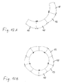
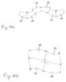
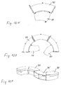
- the first and second table furniture 10, 15 can be assembled in various arcuate, annular, block-like or wave-shaped configurations.
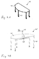
- kit may also include a third table furniture 40, which is in Fig. 4A . 5A, 5B is shown and can serve as a main table, teacher's desk or the like in a compiled table configuration, for example.
- a third table furniture 40 which is in Fig. 4A . 5A, 5B is shown and can serve as a main table, teacher's desk or the like in a compiled table configuration, for example.
- the third table furniture 40 has a table top 42 (for example made of wood and / or plastic).
- this table top 42 has a first pair of opposed long edges 43a, 43b (bottom, top in FIG Fig. 5A ) and a second pair of opposite short edges 43c, 43d (left, right in FIG Fig. 5A ) connecting each of the first pair of edges 43a, 43b.
- one edge 43a of the first edge pair has a convex curvature with the predetermined first curvature radius R1 (same first curvature radius R1 as in the first and second table furniture), and the other edge 43b of the first edge pair is rectilinear.
- the two edges 43c, 43d of the second edge pair of the table top 42 each have a convex curvature with the same first radius of curvature R1.
- concavely curved or rectilinear configurations of the edges 43c, 43d of the second edge pair are also conceivable.
- the table top 42 of this third table furniture 40 is significantly larger than the table top 20 of the first or second table furniture 10, 15.
- the length of the one, convexly curved edge 43 a of the table top 42 at least twice as large as the length of the longer edge 22 c the table top 20 of the first or second table furniture 10, 15, but at least twice as large as the length of the shorter other edge 22d of the table top 20 of the first or second table furniture 10, 15th
- the first radius of curvature R1 is about 110 cm, the length of the edges 43a, 43b of the first pair of edges about 160 cm and the length of the edges 43c, 43d of the second pair of edges about 46 cm, without the invention these dimensions should be limited.
- the third table furniture 40 also has a table frame for supporting the table top 42.
- This table frame has in particular a frame 44 on which the table top 42 rests and is fixed, and (here five) table legs 45.
- the table legs 45 are each equipped with a castor 46.
- all table legs 45 are arranged inside or below the table top 42.
- the table racks of the first table furniture 10, the second table furniture 15 and the third table furniture 40 preferably have substantially the same height H1.
- these third table furniture 40 together with the first table furniture 10 and the second table furniture 15 advantageously in various arcuate, round or block-like configurations assemble.
- the table top 42 on its underside a cable channel 48 or a console with various electrical connections and on its upper side a monitor bracket 49.
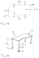
- the kit may further comprise a fourth table furniture 50 which is in Figs. 7A and B is shown.
- the fourth table furniture 50 has a table top 52, which in plan view (see. Fig. 7A ) has a first pair of opposed long edges 58a, 58b and a second pair of opposing short edges 58c, 58d interconnecting each of the first pair of edges 58a, 58b.
- the edges 58a, 58b of the first pair of edges each have a convexity with the first radius of curvature R1 and a concavity with the first radius of curvature R1, these convexities facing each other and these concavities face each other.
- the table top 52 of the fourth table furniture 50 is sized larger than the table tops 20 of the first and second table furniture 10, 15 and has a special "double-waveform".
- the second edge pair 58c, 58d of the table top 52 preferably has a concave curved edge 58c and a convexly curved edge 58d, as in FIG Fig. 7A illustrated, or alternatively two rectilinear edges 58c, 58d.
- the lengths of the edges 58a, 58b of the first edge pair are substantially the same size and also the lengths of the edges 58c, 58d of the second edge pair are substantially the same size.
- the length of the edges 58a, 58b of the first edge pair is, for example, substantially twice as long as the length of the edges 58c, 58d of the second edge pair.
- the length of the edges 58c, 58d of the shorter second edge pair for example, about the same size as the length of the one edge 22c or the length of the other edge 22d of the table top 20 of the first / second table furniture 10, 15th
- the table frame of the fourth table furniture 50 has (here four) table legs 54 in the corner areas of the table top 52, which are preferably each equipped with a caster 56 to allow a simple and comfortable moving the fourth table furniture 50.
- all table legs 45 are arranged inside or below the table top 52 or, for the purpose of space-saving stacking, partly arranged outside the table top 52.
- the table frame also has a frame on which the table top 52 is fixed, or the table legs 54 are attached directly to the table top 52.
- this fourth table furniture 50 with the first table furniture 10, the second table furniture 15 and / or the third table furniture 40 may be assembled into various configurations.
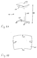
- FIGS. 8A and B show a fifth table furniture 60, which may also be part of the kit.
- the fifth table furniture 60 has a table top 62, which in plan view (see. Fig. 8B ) comprises a first pair of opposing edges and a second pair of opposing edges each connecting the first pair of edges.
- the one edge of the first edge pair (above in Fig. 8B ) has a convex curvature with the first curvature radius R1 and the other edge of the first edge pair (bottom in FIG Fig. 8B ) has a concave curvature with the first radius of curvature R1.
- the edges of the first edge pair have substantially the same length.
- edges of the second edge pair each have a convexity with the first radius of curvature R1 and have substantially the same length.
- the edges of the second edge pair may have a short length or substantially the same length as the edges of the first edge pair.
- the table frame of the fifth table furniture 60 has a bracket 64 for holding the table top 62 and storing objects, a height-adjustable table column 64 and a pedestal 68 with casters, as in Fig. 8A shown.
- the table frame of the fifth table furniture 60 can reach a second height H2, which is greater than the first height H1 of the table frames of the first, second, third and fourth table furniture.
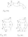
- this fifth table furniture 60 can be seen with the other table furniture (in Fig. 12K for example, 10, 15) of the kit to various table configurations.
- the kit may also include shelf furniture.
- FIGS. 9A to C show a shelf furniture 70 with an arcuate body 72, which can also be assembled with the above-described table furniture 10, 15, 40, 50 to different configurations or workstation arrangements.
- the body 72 of the shelf furniture 70 has in plan view a first pair of opposing sides 73a, 73b and a second pair of opposing sides 73c, 73d respectively connecting the first pair of sides.
- the one side 73a of the first pair of sides has a concave curvature with the first radius of curvature R1 and is substantially, for example closed (eg side wall, perforated plate, etc.) formed.
- the opposite other side 73b of the first pair of sides has a convex curvature with a second radius of curvature R2 which is greater than the first radius of curvature R1, and is designed to be substantially open as a user side.
- the central axes of the two curvatures of the sides 73a, 73b of the first pair of sides of the body 72 lie on a common central axis.
- the sides 73c, 73d of the second side pair of the body 72 thus have substantially the same length.
- the sides 73c, 73d of the second side pair have a rectilinear shape.
- the shelf unit 70 preferably has a third height H3, which is greater than the first height H1 of the various table furniture, so that the shelf furniture 70 can serve as a partition or room divider, for example.
- the body 72 of the shelf furniture 70 is equipped at its bottom with a plurality of casters 76, so that the shelf furniture 70 can be easily moved.
- magnetic connecting elements 74a, 74b are provided on the sides 73c, 73d of the short second side pair.
- a first connecting member 74a and a second connecting member 74b of opposite magnetic polarity or as a magnetic member and a steel member are respectively disposed at predetermined positions on the sides 73c, 73d.
- Two shelf units 70 can thus be pushed together and detachably connected to each other via the magnetic connection elements 74a, 74b to obtain a stable shelf configuration, as exemplified in FIG Fig. 12L is shown.
- the magnetic connecting elements 74a, 74b are arranged at all shelf furniture 70, even if they have different heights H3, each at the same height position.
- two handle members 75 are attached to the top of the body 72 near the sides 73c, 73d of the second side pair.
- the grip elements 75 extend substantially parallel to the sides 73c, 73d of the second side pair. With the help of these handle elements 75, the shelf furniture 70 can be easily grasped and moved.
- the kit may also include other shelf furniture 80 having a substantially cuboidal (substantially rectangular in plan view) body with rectilinear sides of the first and second side pairs.
- this further shelf furniture 80 corresponds to the shelf furniture 70 of FIGS. 9A to C .
- this shelf furniture 70 can be assembled with the table furniture described above (here, for example, 40 or 10) of the kit to various workstation arrangements.
- kit may also include seating.
- Fig. 11 A and B show upholstered seating 90 with an arcuate body 92, which can also be assembled with the table furniture and / or the shelf furniture to various configurations.
- the chair 90 has a body 92 having in plan view a first pair of opposing sides 93a, 93b and a second pair of opposing sides 93c, 93d interconnecting the first pair of sides, respectively.
- the one side 93a of the first pair of sides has a convex curvature with the first radius of curvature R1 and the other side 93b of the first pair of sides has a concave curvature with a third radius of curvature R3 which is smaller than the first radius of curvature R1.
- the central axes of the two curvatures of the sides 93a, 93b of the first pair of sides of the body 92 lie on a common central axis.
- the sides 93c, 93d of the second side pair of the body 92 thus have substantially the same length.
- Fig. 11 A and B have the Pages 93c, 93d of the second side pair has a substantially rectilinear shape.
- the body 92 of the chair 90 is equipped with a plurality of furniture glides 98 at its bottom, so that a floor can be spared when moving the seat 90.
- the seating 90 itself can be assembled in two parts from a kit.
- the kit of the seat furniture 90 has, for example, a box-shaped base 94 and a box-shaped cushion pad 95, which can be connected to each other via a Velcro connection 96. If the base 94 and / or cushion pad 95 are provided at different heights, seating furniture 90 having a number of different overall heights can be variably assembled.
- the kit may also include other seating 91, which have a substantially cuboid (in plan view substantially rectangular) body with rectilinear sides of the first and second side pairs.
- this other seating furniture corresponds to the seating furniture 90 of Figs. 11A and B ,
- the configuration includes a plurality of seats 90 and a variant of the shelf unit 70 'with reduced height; in the example of Fig. 12Q the configuration includes a plurality of circular seating 90, around which several shelves 70 are arranged; and Fig. 12R shows a variant of the configuration of Fig. 12Q , the other seating 91 and other shelves 80 each containing cuboid body.
Landscapes
- Combinations Of Kitchen Furniture (AREA)
- Assembled Shelves (AREA)
- Furniture Connections (AREA)
Description
- Die Erfindung betrifft einen Bausatz zum Erzeugen einer Anordnung von Möbelstücken.
- Tischmöbel gibt es in zahlreichen Ausführungsformen in unterschiedlichen Designs und in unterschiedlichen Größen. Tischplatten von Tischmöbeln haben in Draufsicht zum Beispiel ein erstes Paar von einander gegenüber liegenden Kanten und ein zweites Paar von einander gegenüber liegenden Kanten, welche jeweils das erste Kantenpaar miteinander verbinden. Dabei gibt es auf dem Markt beispielsweise auch Tischmöbel mit Tischplatten, bei denen zumindest ein Teil der Kanten eine konkave oder konvexe Krümmung aufweist. Je nach Ausführung insbesondere der Tischplatten ist es zum Teil schwierig, wenn nicht gar unmöglich, solche Tischmöbel mit gleichen Tischmöbeln, anderen Tischmöbeln oder anderen Möbelstücken in ansprechender und praktischer Weise zu einer Anordnung von Möbelstücken zusammenzustellen.
- Die
DE 93 15 133 U1 offenbart verschiedene Tischplattenelemente für Bürotische, die in Draufsicht ein erstes Paar von einander gegenüber liegenden Kanten und ein zweites Paar von einander gegenüber liegenden Kanten, welche jeweils das erste Kantenpaar miteinander verbinden, aufweisen, wobei die eine Kante des ersten Kantenpaares eine konvexe Krümmung aufweist und die andere Kante des ersten Kantenpaares eine konkave Krümmung aufweist, und die konvexe Krümmung der einen Kante und die konkave Krümmung der anderen Kante des ersten Kantenpaares einen gleich großen Krümmungsradius aufweisen. Bei einem Teil der Tischplattenelemente hat zudem die eine Kante des zweiten Kantenpaares eine größere Länge als die andere Kante des zweiten Kantenpaares. Dabei sind ein erstes Tischplattenelement, bei dem die eine Kante des zweiten Kantenpaares eine konvexe Krümmung aufweist, und ein zweites Tischplattenelement, bei dem die eine Kante des zweiten Kantenpaares eine konkave Krümmung aufweist, offenbart, wobei die konvexen/konkaven Krümmungen der einen Kanten der zweiten Kantenpaare der beiden Tischplattenelemente einen gleich großen Krümmungsradius aufweisen. - Es ist die Aufgabe der Erfindung, einen Bausatz zum Erzeugen einer Anordnung von Möbelstücken zu schaffen, um auf einfache Weise unterschiedliche Arbeitsplätze bzw. Arbeitsplatzanordnungen bereitstellen zu können.
- Diese Aufgabe wird gelöst durch einen Bausatz zum Erzeugen einer Anordnung von Möbelstücken mit den Merkmalen des Anspruches 1.
- Mit diesem Bausatz können auf einfache und zugleich variable Weise Anordnungen von Möbelstücken zusammengestellt werden, um zum Beispiel unterschiedliche Arbeitsplätze / Arbeitsplatzanordnungen für eine oder mehrere Personen zu schaffen. Die konvex und konkav gekrümmten Kanten der Tischplatten können aufgrund des gleich gewählten Krümmungsradius im Wesentlichen ohne Freiräume dazwischen zusammengestellt werden, sodass sich ein im Wesentlichen geschlossener Arbeitsbereich innerhalb der Anordnung über mehrere Möbelstücke hinweg ergeben kann.
- Das Tischmöbel für den Bausatz der Erfindung weist eine Tischplatte und ein die Tischplatte tragendes Tischgestell auf, wobei die Tischplatte in Draufsicht ein erstes Paar von einander gegenüber liegenden Kanten und ein zweites Paar von einander gegenüber liegenden Kanten, welche jeweils das erste Kantenpaar miteinander verbinden, aufweist. Dabei weist die eine Kante des ersten Kantenpaares eine konvexe Krümmung auf und weist die andere Kante des ersten Kantenpaares eine konkave Krümmung auf. Die konvexe Krümmung der einen Kante und die konkave Krümmung der anderen Kante des ersten Kantenpaares weisen einen im Wesentlichen gleich großen, vorbestimmten ersten Krümmungsradius auf, und die eine Kante des zweiten Kantenpaares hat eine größere Länge als die andere Kante des zweiten Kantenpaares.
- Ein Tischmöbel mit einer derart konzipierten Tischplatte kann auf vielfältige Weise mit gleichen oder gleichartigen Tischmöbeln und/oder anderen Möbelstücken zusammengestellt werden, um auf einfache Weise unterschiedliche Arbeitsplätze / Arbeitsplatzanordnungen für einen oder mehrere Personen zu schaffen. Die konvex und konkav gekrümmten Kanten der Tischplatte dieser Tischmöbel können aufgrund des gleich gewählten Krümmungsradius im Wesentlichen ohne Freiräume dazwischen zusammengestellt werden, sodass sich eine im Wesentlichen geschlossene Arbeitsfläche über die Tischplatten mehrerer Tischmöbel hinweg ergeben kann. Insbesondere können zwei solche Tischmöbel an ihrem ersten Kantenpaar aneinander gestellt werden, da die beiden einander gegenüber liegenden Kanten des ersten Kantenpaares als konvex/konkav gekrümmtes Kantenpaar mit dem gleichen Krümmungsradius ausgebildet sind.
- Das Tischmöbel bietet durch die asymmetrische Formgebung seiner Tischplatte zudem ein formschönes Design, welches von herkömmlichen Tischmöbeln mit häufig symmetrisch konzipierten Tischplatten abweicht.
- Der Bausatz der Erfindung kann in besonders vorteilhafter Weise in Schulen und anderen Lehranstalten, Seminarräumen, Besprechungsräumen, Großraumbüros, etc. eingesetzt werden. Es können dort variable und praktische (Tisch-) Möbelanordnungen für ein oder mehrere Personen erzeugt werden.
- Zur Konstruktion einer Tischplatte eines solchen Tischmöbels fallen die Mittelpunkte der Krümmungsradien der einen und der anderen Kante des ersten Kantenpaares nicht zusammen, und auch die radialen Mittelachsen ihrer Krümmungen fallen nicht zusammen, weshalb die Kanten des zweiten Kantenpaares unterschiedlich lang sind.
- Die Tischplatten der Tischmöbel sind grundsätzlich aus einem beliebigen Material oder einer beliebigen Materialkombination gefertigt. Vorzugsweise können für die Tischplatten Kunststoff-, Holz-, Metall- und Glasmaterialien eingesetzt werden. Die Tischgestelle der Tischmöbel sind grundsätzlich ebenfalls aus einem beliebigen Material oder einer beliebigen Materialkombination gefertigt. Vorzugsweise können für die Tischgestelle Kunststoff-, Holz- und metallische Materialien eingesetzt werden.
- Die Begriffe "konvexe Krümmung" bzw. "Konvexität" bezeichnen in diesem Zusammenhang eine Wölbung einer jeweiligen Kante der Tischplatte in Draufsicht auf die Tischplatte nach außen. Die Begriffe "konkave Krümmung" bzw. "Konkavität" bezeichnen in diesem Zusammenhang eine Wölbung einer jeweiligen Kante der Tischplatte in Draufsicht auf die Tischplatte nach innen. Die Kanten des ersten Kantenpaares der Tischplatte weisen jeweils vorzugsweise genau eine konvexe bzw. konkave Krümmung auf. Diese Krümmungen erstrecken sich jeweils vorzugsweise im Wesentlichen über die gesamte Länge der Kanten. Die konvexe / konkave Krümmung einer Kante der Tischplatte hat vorzugsweise einen im Wesentlichen konstanten Krümmungsradius entlang der gesamten Wölbung. Im Fall von optional abgerundeten Ecken zwischen den Kanten des ersten und des zweiten Kantenpaares gehen die konvexe und die konkave Krümmung jeweils vorzugsweise im Wesentlichen tangential, d.h. ohne eine Kante (im mathematischen Sinne ohne eine Unstetigkeit) in die Rundung der jeweiligen Ecke über. Der erste vorbestimmte Krümmungsradius liegt vorzugsweise im Bereich von etwa 80 cm bis etwa 150 cm, besonders bevorzugt beträgt er etwa 110 cm.
- In einer bevorzugten Ausgestaltung der Erfindung weist die andere Kante des zweiten Kantenpaares der Tischplatte eine konvexe Krümmung mit dem ersten Krümmungsradius, eine konkave Krümmung mit dem ersten Krümmungsradius oder eine im Wesentlichen geradlinige Gestalt auf.
- Da alle (konvexen oder konkaven) Krümmungen der Kanten der Tischplatte den gleichen ersten Krümmungsradius aufweisen, können diese Tischplatten variabel und vorzugsweise im Wesentlichen ohne Zwischenräume dazwischen zusammengestellt werden. Ebenso können diese Tischplatten mit anderen (Tisch-)Möbelstücken variabel und vorzugsweise im Wesentlichen ohne Zwischenräume dazwischen zusammengestellt werden, wenn diese ebenfalls eine Kante oder Seite mit einer konvexen oder konkaven Krümmung mit diesem ersten Krümmungsradius haben.
- In einer bevorzugten Ausführungsform des Tischmöbels weist die eine Kante des zweiten Kantenpaares der Tischplatte eine konvexe Krümmung auf und weist die andere Kante des zweiten Kantenpaares der Tischplatte ebenfalls eine konvexe Krümmung oder eine geradlinige Gestalt auf. In einer alternativen bevorzugten Ausführungsform des Tischmöbels weist die eine Kante des zweiten Kantenpaares der Tischplatte eine konkave Krümmung auf und weist die andere Kante des zweiten Kantenpaares der Tischplatte ebenfalls eine konkave Krümmung oder eine geradlinige Gestalt auf.
- In einer bevorzugten Ausgestaltung der Erfindung überspannt die Tischplatte in Draufsicht ein Kreisringsegment mit einem Öffnungswinkel, der ausgewählt ist aus 30°, 36°, 45°, 60°, 72° und 90°. Erfindungsgemäße Tischmöbel mit diesen Winkelmaßen können besonders einfach in Bogen- oder Kreisform zusammengestellt werden.
- In einer bevorzugten Ausgestaltung der Erfindung weist das Tischgestell mehrere Tischbeine auf, von denen wenigstens ein Tischbein in der Draufsicht außerhalb der Tischplatte angeordnet ist. Vorzugsweise weist das Tischgestell insgesamt vier Tischbeine in den Eckbereichen der Tischplatte auf, von denen zwei oder drei (in Draufsicht) außerhalb der Tischplatte angeordnet sind. Aufgrund der in diesem Sinne außerhalb der Tischplatte angeordneten Tischbeine können die Tischmöbel zwecks Aufbewahrung oder Transport platzsparend aufeinander gestapelt werden. Insbesondere kann beim Stapeln mehrerer Tischmöbel die Tischplatte eines unteren Tischmöbels zwischen den Tischbeinen eines oberen Tischmöbels platziert werden, sodass die Tischmöbel ineinander geschachtelt werden können.
- In einer weiteren bevorzugten Ausgestaltung der Erfindung weist das Tischgestell mehrere Tischbeine auf, von denen die Tischbeine im Bereich der einen Kante oder der anderen Kante eines der Kantenpaare der Tischplatte jeweils mit einer Fußrolle ausgestattet sind, und weist die Tischplatte im Bereich der anderen Kante oder der einen Kante des einen Kantenpaares wenigstens eine Hilfsvorrichtung zum Greifen der Tischplatte auf. Bei dieser Konstruktion kann das Tischmöbel im Bereich einer Kante der Tischplatte an der Hilfsvorrichtung gegriffen und leicht angehoben werden, um dann über die Fußrollen im Bereich der gegenüber liegenden Kante einfach verschoben zu werden. Durch diese Maßnahme ist ein Verändern einer Anordnung von mehreren solchen Tischmöbeln auf einfache und bequeme Weise möglich.
- In einer anderen Ausgestaltung der Erfindung können wahlweise auch alle Tischbeine des Tischgestells mit Fußrollen ausgestattet sein, um ein einfaches und bequemes Verschieben des Tischmöbels zu ermöglichen.
- In einer weiteren bevorzugten Ausgestaltung der Erfindung ist das Tischgestell als ein höhenverstellbares Tischgestell ausgebildet.
- In einer noch weiteren Ausgestaltung der Erfindung ist die Tischplatte des Tischmöbels, zum Beispiel an ihrer Unterseite und/oder ihrer Oberseite mit wenigstens einer elektrischen Anschlussvorrichtung für ein elektronisches Gerät ausgestattet. Zu den elektrischen Anschlussvorrichtungen zählen in diesem Zusammenhang insbesondere Stecker und Steckerleisten für eine Energieversorgung, eine Telefonverbindung, eine Datenverbindung, eine Netzverbindung und dergleichen.
- Vorzugsweise sind die Längen aller Kanten der Tischplatten der ersten und zweiten Tischmöbel jeweils zueinander gleich groß, sodass die Tischplatten der ersten und zweiten Tischmöbel - bezogen auf die Positionen ihrer Ecken zwischen den Kanten - im Wesentlichen gleich groß sind.
- In einer bevorzugten Ausgestaltung der Erfindung weist der Bausatz (alternativ oder zusätzlich) wenigstens ein drittes Tischmöbel mit einer Tischplatte und einem die Tischplatte tragenden Tischgestell auf, wobei die Tischplatte in Draufsicht ein erstes Paar von einander gegenüber liegenden Kanten und ein zweites Paar von einander gegenüber liegenden Kanten, welche jeweils das erste Kantenpaar miteinander verbinden, aufweist, wobei die eine Kante des ersten Kantenpaares der Tischplatte des dritten Tischmöbels eine konvexe Krümmung mit dem ersten Krümmungsradius aufweist, und wobei eine Länge der einen Kante des ersten Kantenpaares der Tischplatte des dritten Tischmöbels wenigstens so groß ist wie das Zweifache einer Länge der anderen Kante des zweiten Kantenpaares der Tischplatte des ersten Tischmöbels oder des zweiten Tischmöbels. Vorzugsweise ist die Länge der einen Kante des ersten Kantenpaares der Tischplatte des dritten Tischmöbels wenigstens so groß ist wie das Zweifache der Länge der einen Kante des zweiten Kantenpaares der Tischplatte des ersten Tischmöbels oder des zweiten Tischmöbels.
- Die Tischplatte des dritten Tischmöbels ist (deutlich) größer bemessen als die Tischplatten der ersten und zweiten Tischmöbel, weshalb das dritte Tischmöbel vorzugsweise als Mastertisch, Lehrertisch, Diskussionsleitertisch, etc. in einer Anordnung von Tischmöbeln genutzt werden kann. Aufgrund des übereinstimmenden ersten Krümmungsradius bei den gekrümmten Kanten der Tischplatten der ersten, zweiten und dritten Tischmöbel können diese variabel zu unterschiedlichen Arbeitsplätzen / Arbeitsplatzanordnungen zusammengestellt werden.
- Die Tischplatte dieses dritten Tischmöbels weist vorzugsweise wenigstens ein weiteres Merkmal auf, welches ausgewählt ist aus einer anderen Kante des ersten Kantenpaares mit einer im Wesentlichen geradlinigen Gestalt, einer einen Kante des zweiten Kantenpaares mit einer konvexen Krümmung mit dem ersten Krümmungsradius, einer konkaven Krümmung mit dem ersten Krümmungsradius oder einer im Wesentlichen geradlinigen Gestalt, und einer anderen Kante des zweiten Kantenpaares mit einer konvexen Krümmung mit dem ersten Krümmungsradius, einer konkaven Krümmung mit dem ersten Krümmungsradius oder einer im Wesentlichen geradlinigen Gestalt.
- In einer bevorzugten Ausgestaltung der Erfindung sind die Tischbeine des Tischgestells des dritten Tischmöbels mit Fußrollen ausgestattet, um ein einfaches und bequemes Verschieben des dritten Tischmöbels zu ermöglichen.
- In einer weiteren bevorzugten Ausgestaltung der Erfindung ist das Tischgestell des dritten Tischmöbels als ein höhenverstellbares Tischgestell ausgebildet.
- In einer noch weiteren Ausgestaltung der Erfindung ist die Tischplatte des dritten Tischmöbels, zum Beispiel an ihrer Unterseite und/oder ihrer Oberseite mit wenigstens einer elektrischen Anschlussvorrichtung für ein elektronisches Gerät ausgestattet. Zu den elektrischen Anschlussvorrichtungen zählen in diesem Zusammenhang insbesondere Stecker und Steckerleisten für eine Energieversorgung, eine Telefonverbindung, eine Datenverbindung, eine Netzverbindung und dergleichen.
- In einer bevorzugten Ausgestaltung der Erfindung weist der Bausatz (alternativ oder zusätzlich) wenigstens ein viertes Tischmöbel mit einer Tischplatte und einem die Tischplatte tragenden Tischgestell auf, wobei die Tischplatte in Draufsicht ein erstes Paar von einander gegenüber liegenden Kanten und ein zweites Paar von einander gegenüber liegenden Kanten, welche jeweils das erste Kantenpaar miteinander verbinden, aufweist, wobei die Kanten des ersten Kantenpaares der Tischplatte des vierten Tischmöbels jeweils eine Konvexität mit dem ersten Krümmungsradius und eine Konkavität mit dem ersten Krümmungsradius aufweisen, wobei diese Konvexitäten einander gegenüber liegen und diese Konkavitäten einander gegenüber liegen.
- Die Tischplatte des vierten Tischmöbels ist größer bemessen als die Tischplatten der ersten und zweiten Tischmöbel und besitzt eine spezielle "Doppelwellenform". Aufgrund des übereinstimmenden ersten Krümmungsradius bei den gekrümmten Kanten der Tischplatten der ersten, zweiten, dritten und vierten Tischmöbel können diese variabel zu unterschiedlichen Arbeitsplätzen / Arbeitsplatzanordnungen zusammengestellt werden.
- Die Tischplatte dieses vierten Tischmöbels weist vorzugswiese wenigstens ein weiteres Merkmal auf, welches ausgewählt ist aus einer Länge der Kanten des ersten Kantenpaares im Wesentlichen doppelt so groß wie eine Länge der Kanten des zweiten Kantenpaares, einer einen Kante des zweiten Kantenpaares mit einer konvexen Krümmung mit dem ersten Krümmungsradius, einer konkaven Krümmung mit dem ersten Krümmungsradius oder einer im Wesentlichen geradlinigen Gestalt, einer anderen Kante des zweiten Kantenpaares mit einer konvexen Krümmung mit dem ersten Krümmungsradius, einer konkaven Krümmung mit dem ersten Krümmungsradius oder einer im Wesentlichen geradlinigen Gestalt, und einer Länge der Kanten des zweiten Kantenpaares im Wesentlichen gleich einer Länge der einen Kante oder der anderen Kanten des zweiten Kantenpaares der Tischplatte des ersten oder zweiten Tischmöbels.
- In einer bevorzugten Ausgestaltung der Erfindung sind die Tischbeine des Tischgestells des vierten Tischmöbels mit Fußrollen ausgestattet, um ein einfaches und bequemes Verschieben des vierten Tischmöbels zu ermöglichen.
- In einer weiteren bevorzugten Ausgestaltung der Erfindung ist das Tischgestell des vierten Tischmöbels als ein höhenverstellbares Tischgestell ausgebildet.
- In einer noch weiteren Ausgestaltung der Erfindung ist die Tischplatte des vierten Tischmöbels, zum Beispiel an ihrer Unterseite und/oder ihrer Oberseite mit wenigstens einer elektrischen Anschlussvorrichtung für ein elektronisches Gerät ausgestattet. Zu den elektrischen Anschlussvorrichtungen zählen in diesem Zusammenhang insbesondere Stecker und Steckerleisten für eine Energieversorgung, eine Telefonverbindung, eine Datenverbindung, eine Netzverbindung und dergleichen.
- In einer bevorzugten Ausgestaltung der Erfindung haben die Tischgestelle je nach Bausatz der Tischmöbel, ersten Tischmöbel, zweiten Tischmöbel, dritten Tischmöbel und vierten Tischmöbel alle eine im Wesentlichen gleiche vorbestimmte Höhe.
- In einer bevorzugten Ausgestaltung der Erfindung weist der Bausatz (alternativ oder zusätzlich) wenigstens ein Regalmöbel auf mit einem Korpus, der in Draufsicht ein erstes Paar von einander gegenüber liegenden Seiten und ein zweites Paar von einander gegenüber liegenden Seiten, welche jeweils das erste Seitenpaar miteinander verbinden, aufweist, wobei die eine Seite des ersten Seitenpaares eine konkave Krümmung mit dem ersten Krümmungsradius aufweist.
- Aufgrund des übereinstimmenden ersten Krümmungsradius bei den gekrümmten Kanten der Tischmöbel und der gekrümmten Seiten der Regalmöbel können diese variabel zu unterschiedlichen Arbeitsplätzen / Arbeitsplatzanordnungen zusammengestellt werden.
- Das Regalmöbel weist wenigstens ein weiteres Merkmal auf, welches ausgewählt ist aus einer einen Seite des ersten Seitenpaares des Korpus mit einer im Wesentlichen geschlossenen Gestalt; einer anderen Seite des ersten Seitenpaares des Korpus mit einer konvexen Krümmung mit einem zweiten Krümmungsradius, der größer ist als der erste Krümmungsradius; Seiten des zweiten Seitenpaares des Korpus mit einer im Wesentlichen geradlinigen Gestalt; wenigstens einer vorzugsweise magnetischen Verbindungsvorrichtung an den Seiten des zweiten Seitenpaares des Korpus; einen mit Fußrollen ausgestatteten Korpus; Griffelementen am Korpus; einen im Wesentlichen radialen Verlauf des zweiten Seitenpaares des Korpus, bezogen auf die Krümmung der einen Seite des ersten Seitenpaares des Korpus; Mittelpunkten der Krümmungen der einen Seite und der anderen Seite des ersten Seitenpaares des Korpus auf einer gemeinsamen Mittelachse, bezogen auf die Krümmungen; einen gleichen Mittelpunkt der Krümmungen der einen Seite und der anderen Seite des ersten Seitenpaares des Korpus; und einer Höhe des Korpus größer oder im Wesentlichen gleich der Höhe der Tischmöbel des Bausatzes.
- In einer weiteren Ausgestaltung der Erfindung weist der Bausatz ferner wenigstens ein weiteres Regalmöbel auf mit einem mit einem Korpus, der in Draufsicht ein erstes Paar von einander gegenüber liegenden Seiten und ein zweites Paar von einander gegenüber liegenden Seiten, welche jeweils das erste Seitenpaar miteinander verbinden, aufweist, wobei die Seiten des Korpus alle eine im Wesentlichen geradlinige Gestalt aufweisen. Das weitere Regalmöbel hat mit anderen Worten einen in Draufsicht im Wesentlichen rechteckig ausgestalteten Korpus.
- In einer Ausgestaltung der Erfindung weist der Bausatz (alternativ oder zusätzlich) wenigstens ein Sitzmöbel auf mit einem Korpus, der in Draufsicht ein erstes Paar von einander gegenüber liegenden Seiten und ein zweites Paar von einander gegenüber liegenden Seiten, welche jeweils das erste Seitenpaar miteinander verbinden, aufweist, wobei die eine Seite des ersten Seitenpaares eine konvexe Krümmung mit dem ersten Krümmungsradius aufweist.
- Aufgrund des übereinstimmenden ersten Krümmungsradius bei den gekrümmten Kanten der Tischmöbel und der gekrümmten Seiten der Regalmöbel und der Sitzmöbel können diese variabel zu unterschiedlichen Arbeitsplätzen / Arbeitsplatzanordnungen zusammengestellt werden.
- Das Sitzmöbel weist zudem wenigstens ein weiteres Merkmal auf, welches ausgewählt ist aus einer anderen Seite des ersten Seitenpaares des Korpus mit einer konkaven Krümmung mit einem dritten Krümmungsradius, der kleiner ist als der erste Krümmungsradius; Seiten des zweiten Seitenpaares des Korpus mit einer im Wesentlichen geradlinigen Gestalt; einem als Polstersitzmöbel ausgestalteten Korpus; einem als Bausatz aus wenigstens zwei Komponenten ausgebildeten Korpus; variabel auswählbaren Höhen des Korpus durch eine Ausbildung als Bausatz; einem im Wesentlichen radialen Verlauf des zweiten Seitenpaares des Korpus, bezogen auf die Krümmung der einen Seite des ersten Seitenpaares; Mittelpunkten der Krümmungen der einen Seite und der anderen Seite des ersten Seitenpaares des Korpus auf einer gemeinsamen Mittelachse, bezogen auf die Krümmungen; einen gleichen Mittelpunkt der Krümmungen der einen Seite und der anderen Seite des ersten Seitenpaares des Korpus; und einer Höhe des Korpus kleiner oder im Wesentlichen gleich der Höhe der Tischmöbel des Bausatzes.
- In einer weiteren Ausgestaltung der Erfindung weist der Bausatz ferner wenigstens ein weiteres Sitzmöbel auf mit einem mit einem Korpus, der in Draufsicht ein erstes Paar von einander gegenüber liegenden Seiten und ein zweites Paar von einander gegenüber liegenden Seiten, welche jeweils das erste Seitenpaar miteinander verbinden, aufweist, wobei die Seiten des Korpus alle eine im Wesentlichen geradlinige Gestalt aufweisen. Das weitere Sitzmöbel hat mit anderen Worten einen in Draufsicht im Wesentlichen rechteckig ausgestalteten Korpus.
- In einer noch weiteren Ausgestaltung der Erfindung weist der Bausatz (alternativ oder zusätzlich) wenigstens ein fünftes Tischmöbel mit einer Tischplatte und einem die Tischplatte tragenden Tischgestell auf, wobei die Tischplatte in Draufsicht ein erstes Paar von einander gegenüber liegenden Kanten und ein zweites Paar von einander gegenüber liegenden Kanten, welche jeweils das erste Kantenpaar miteinander verbinden, aufweist, wobei wenigstens eine Kante des ersten Kantenpaares eine konvexe Krümmung mit dem ersten Krümmungsradius aufweist, und wobei das Tischgestell eine höhenverstellbare Tischsäule aufweist.
- Dieses fünfte Tischmöbel weist vorzugsweise wenigstens ein weiteres Merkmal auf, welches ausgewählt ist aus einer konvexen Krümmung mit dem ersten Krümmungsradius an allen Kanten des ersten und des zweiten Kantenpaares der Tischplatte; einem mit Fußrollen ausgestatteten Tischgestell; einer Konsole an der Unterseite der Tischplatte; wenigstens einer elektrischen Anschlussvorrichtung für ein elektronisches Gerät an der Unterseite und/oder der Oberseite der Tischplatte; und dergleichen.
- Die oben genannten bevorzugten Ausgestaltungen der Erfindung können in beliebiger Weise ein- oder mehrfach miteinander kombiniert werden.
- Obige sowie weitere Merkmale und Vorteile der Erfindung werden aus der nachfolgenden Beschreibung bevorzugter, nicht-einschränkender Ausführungsbeispiele anhand der beiliegenden Zeichnungen besser verständlich. Darin zeigen, größtenteils schematisch:
- Fig. 1
- eine perspektivische Ansicht eines ersten Tischmöbels und eines zweiten Tischmöbels gemäß einem Ausführungsbeispiel der Erfindung;
- Fig. 2A
- eine Draufsicht des ersten Tischmöbels von
Fig. 1 gemäß einem Ausführungsbeispiel der Erfindung; - Fig. 2B
- eine Unteransicht des ersten Tischmöbels von
Fig. 1 gemäß einem Ausführungsbeispiel der Erfindung; - Fig. 2C
- eine Seitenansicht des ersten Tischmöbels von
Fig. 1 gemäß einem Ausführungsbeispiel der Erfindung; - Fig. 3
- eine Prinzipskizze einer ersten beispielhaften Anordnung eines ersten und eines zweiten Tischmöbels der Erfindung;
- Fig. 4A
- eine perspektivische Ansicht eines dritten Tischmöbels gemäß einem Ausführungsbeispiel der Erfindung;
- Fig. 4B
- eine perspektivische Ansicht einer Variante des dritten Tischmöbels gemäß einem Ausführungsbeispiel der Erfindung;
- Fig. 5A
- eine Unteransicht des dritten Tischmöbels von
Fig. 4A oder 4B gemäß einem Ausführungsbeispiel der Erfindung; - Fig. 5B
- eine Seitenansicht des dritten Tischmöbels von
Fig. 4A oder 4B gemäß einem Ausführungsbeispiel der Erfindung; - Fig. 6
- eine Prinzipskizze einer beispielhaften Anordnung einer Variante eines ersten und eines zweiten Tischmöbels der Erfindung;
- Fig. 7A
- eine Draufsicht eines vierten Tischmöbels gemäß einem Ausführungs-beispiel der Erfindung;
- Fig. 7B
- eine perspektivische Ansicht eines vierten Tischmöbels gemäß einem Ausführungsbeispiel der Erfindung;
- Fig. 8A
- eine perspektivische Ansicht eines fünften Tischmöbels gemäß einem Ausführungsbeispiel der Erfindung;
- Fig. 8B
- eine Draufsicht des fünften Tischmöbels von
Fig. 8A ; - Fig. 9A
- eine perspektivische Ansicht eines Regalmöbels gemäß einem Ausführungsbeispiel der Erfindung;
- Fig. 9B
- eine Draufsicht des Regalmöbels von
Fig. 9A gemäß einem Ausführungsbeispiel der Erfindung; - Fig. 9C
- eine Seitenansicht des Regalmöbels von
Fig. 9A gemäß einem Ausführungsbeispiel der Erfindung; - Fig. 10
- eine perspektivische Ansicht eines weiteren Regalmöbels gemäß einem Ausführungsbeispiel der Erfindung;
- Fig. 11A
- eine Draufsicht eines Sitzmöbels gemäß einem Ausführungsbeispiel der Erfindung;
- Fig. 11B
- eine perspektivische Explosionsdarstellung des Sitzmöbels von
Fig. 11 A gemäß einem Ausführungsbeispiel der Erfindung; und - Fig. 12A bis R
- Prinzipskizzen von verschiedenen beispielhaften Anordnungen von Möbelstücken gemäß der Erfindung.
- Bezug nehmend auf
Fig. 1 bis 2C werden zunächst ein erstes Tischmöbel 10 und ein zweites Tischmöbel 15 der Erfindung näher erläutert. Die ersten und zweiten Tischmöbel 10, 15 gehören zum Beispiel zu einem Bausatz zum Erzeugen einer Anordnung von Möbelstücken. -
Fig. 2A-C zeigen jeweils nur das erste Tischmöbel, das zweite Tischmöbel ist analog konstruiert und deshalb nicht zusätzlich dargestellt. - Das erste Tischmöbel 10 weist eine Tischplatte 20 (zum Beispiel aus Holz und/oder Kunststoff) auf. In der Draufsicht (vgl.
Fig. 2A ) hat diese Tischplatte 20 ein erstes Paar von einander gegenüber liegenden Kanten 22a, 22b (unten, oben inFig. 2A ) und ein zweites Paar von einander gegenüber liegenden Kanten 22c, 22d (links, rechts inFig. 2A ), welche jeweils das erste Kantenpaar 22a, 22b miteinander verbinden. Wie inFig. 2A dargestellt, weist die eine Kante 22a des ersten Kantenpaares eine konvexe, d.h. nach außen gebogene Krümmung mit einem vorbestimmten ersten Krümmungsradius R1 auf und weist die andere Kante 22b des ersten Kantenpaares eine konkave, d.h. nach innen gebogene Krümmung mit dem gleichen vorbestimmten Krümmungsradius R1 auf. - Die (fiktiven) Konstruktions-Mittelpunkte der beiden Krümmungen der Kanten 22a, 22b des ersten Kantenpaares fallen nicht zusammen und auch die (fiktiven) Mittelachsen der beiden Krümmungen der Kanten 22a, 22b des ersten Kantenpaares fallen nicht zusammen, sodass im Ergebnis die eine Kante 22c (links in
Fig. 2A ) des zweiten Kantenpaares eine größere Länge als die andere Kante 22d (rechts inFig. 2A ) des zweiten Kantenpaares hat. Es ergibt sich somit insgesamt eine asymmetrische Gestaltung der Tischplatte 20. Neben den funktionellen Vorteilen ergibt sich so auch ein formschönes Design des Tischmöbels. - Wie in
Fig. 2A dargestellt, weisen die Kanten 22a, 22b jeweils genau eine Krümmung (Konvexität bzw. Konkavität) auf, welche sich im Wesentlichen über die gesamte Länge der jeweiligen Kante erstreckt. Außerdem gehen diese Krümmungen vorzugsweise tangential, d.h. fließend in die abgerundeten Ecken der Tischplatte 20 über. - In einer bevorzugten Ausführungsform betragen der erste Krümmungsradius R1 etwa 110 cm, die Länge der einen Kante 22a des ersten Kantenpaares etwa 97 cm, die Länge der anderen Kante 22b des ersten Kantenpaares etwa 67 cm, die Länge der einen Kante 22c des zweiten Kantenpaares etwa 54 cm, die Länge der anderen Kante 22d des zweiten Kantenpaares etwa 39 cm und ein Öffnungswinkel W etwa 36°, ohne dass die Erfindung auf diese Maßebeschränkt sein soll.
- Wie in
Fig. 2B und2C dargestellt, weist das erste Tischmöbel 10 zudem ein Tischgestell zum Tragen der Tischplatte 20 auf. Dieses Tischgestell weist insbesondere ein Rahmengestell 26, an/auf welchem die Tischplatte 20 befestigt ist, und (hier vier) Tischbeine 27 in den Eckbereichen der Tischplatte 20 auf. Ein Teil der Tischbeine 27 (alternativ auch alle Tischbeine) ist jeweils mit einer Fußrolle 28 ausgestattet. - In diesem Ausführungsbeispiel ist ein Teil der Tischbeine 27 außerhalb der Tischplatte 20 angeordnet (vgl. Draufsicht von
Fig. 2A ), in diesem Fall insgesamt drei der vier Tischbeine. Durch diese Maßnahme ist es möglich, mehrere dieser Tischmöbel 10 stabil aufeinander zu stapeln. Dabei umgreifen die außen liegenden Tischbeine 27 eines oberen Tischmöbels 10 die Tischplatte 20 eines unteren Tischmöbels 10 und sind die Tischplatten 20 der Tischmöbel quer zur Stapelrichtung etwas zueinander versetzt. - Außerdem sind in diesem Ausführungsbeispiel nur die zwei Tischbeine 27 im Bereich der einen Kante 22c des zweiten Kantenpaares der Tischplatte 20 mit Fußrollen 28 ausgestattet. Im Bereich der anderen Kante 22d des zweiten Kantenpaares sind eine erste Hilfsvorrichtung 24a an der Oberseite der Tischplatte 20 (vgl.
Fig. 2A ) und eine zweite Hilfsvorrichtung 24b an der Unterseite der Tischplatte 20 (vgl.Fig. 2B ) vorgesehen. Bei den Hilfsvorrichtungen 24a, 24b handelt es sich zum Beispiel um farbige und/oder haptische Markierungen. Ein Benutzer kann die Tischplatte 20 an den Hilfsvorrichtungen 24a, 24b greifen und das Tischmöbel 20 so an der anderen Kante 22d des zweiten Kantenpaares anheben und über die Fußrollen 28 an den Tischbeinen 27 an der gegenüber liegenden einen Kante 22c des zweiten Kantenpaares einfach verschieben. Die Tischbeine 27 mit Fußrollen 28 sind dabei insgesamt genauso hoch wie die Tischbeine 27 ohne Fußrollen 28 allein. - Bei dem gezeigten ersten Tischmöbel 10 weisen auch die Kanten 22c, 22d des zweiten Kantenpaares der Tischplatte 20 jeweils eine konvexe Krümmung mit dem gleichen ersten Krümmungsradius R1 auf. Das zweite Tischmöbel 15 unterscheidet sich von diesem ersten Tischmöbel 10 dadurch, dass die beiden Kanten 22c, 22d des zweiten Kantenpaares der Tischplatte 20 jeweils eine konkave Krümmung mit dem gleichen ersten Krümmungsradius R1 aufweisen.
- Außerdem sind die einen konvex gekrümmten Kanten 22a des ersten Kantenpaares, die anderen konkav gekrümmten Kanten 22b des ersten Kantenpaares, die einen längeren, konvex bzw. konkav gekrümmten Kanten 22c des zweiten Kantenpaares und die anderen kürzeren, konvex bzw. konkav gekrümmten Kanten 22d des zweiten Kantenpaares beim ersten und zweiten Tischmöbel 10, 15 jeweils mit den gleichen Längen ausgebildet. Wie beispielhaft in
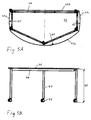
Fig. 3 veranschaulicht, lassen sich daher ein erstes Tischmöbel 10 und ein zweites Tischmöbel 15 vorteilhaft im Wesentlichen spaltfrei zusammenstellen. -
Fig. 6 zeigt eine Variante der ersten und zweiten Tischmöbel 30, 35. Bei dieser Variante haben die kürzeren anderen Kanten 22d des zweiten Kantenpaares der Tischplatte 20 jeweils eine im Wesentlichen geradlinige Gestalt. Wie dargestellt, lassen sich auch diese ersten Tischmöbel 30 und zweiten Tischmöbel 35 vorteilhaft im Wesentlichen spaltfrei zusammenstellen. - Ein Bausatz zum Erzeugen einer Anordnung von Möbelstücken enthält vorzugsweise die ersten Tischmöbel 10 und die zweiten Tischmöbel 15 oder deren Varianten 30, 35. Alternativ kann der Bausatz auch nur erste oder zweite Tischmöbel aufweisen.
- Wie in
Fig. 12A bis D beispielhaft veranschaulicht, können die ersten und zweiten Tischmöbel 10, 15 in verschiedenen bogenförmigen, kreisringförmigen, blockartigen oder wellenförmigen Konfigurationen zusammengestellt werden. - Ferner kann der Bausatz auch ein drittes Tischmöbel 40 enthalten, welches in
Fig. 4A ,5A, 5B dargestellt ist und beispielsweise als Haupttisch, Lehrertisch oder dergleichen in einer zusammengestellten Tischkonfiguration dienen kann. - Das dritte Tischmöbel 40 weist eine Tischplatte 42 (zum Beispiel aus Holz und/oder Kunststoff) auf. In der Draufsicht hat diese Tischplatte 42 ein erstes Paar von einander gegenüber liegenden langen Kanten 43a, 43b (unten, oben in
Fig. 5A ) und ein zweites Paar von einander gegenüber liegenden kurzen Kanten 43c, 43d (links, rechts inFig. 5A ), welche jeweils das erste Kantenpaar 43a, 43b miteinander verbinden. Wie inFig. 5A dargestellt, weist die eine Kante 43a des ersten Kantenpaares eine konvexe Krümmung mit dem vorbestimmten ersten Krümmungsradius R1 (gleicher erster Krümmungsradius R1 wie bei den ersten und zweiten Tischmöbeln) auf und ist die andere Kante 43b des ersten Kantenpaares geradlinig ausgestaltet. - Die beiden Kanten 43c, 43d des zweiten Kantenpaares der Tischplatte 42 weisen jeweils eine konvexe Krümmung mit dem gleichen ersten Krümmungsradius R1 auf. Alternativ sind auch konkav gekrümmte oder geradlinige Ausgestaltungen der Kanten 43c, 43d des zweiten Kantenpaares denkbar.
- Die Tischplatte 42 dieses dritten Tischmöbels 40 ist deutlich größer dimensioniert als die Tischplatte 20 des ersten oder zweiten Tischmöbels 10, 15. Vorzugsweise ist die Länge der einen, konvex gekrümmten Kante 43a der Tischplatte 42 wenigstens doppelt so groß wie die Länge der längeren einen Kante 22c der Tischplatte 20 des ersten oder zweiten Tischmöbels 10, 15, zumindest aber wenigstens doppelt so groß wie die Länge der kürzeren anderen Kante 22d der Tischplatte 20 des ersten oder zweiten Tischmöbels 10, 15.
- In einer bevorzugten Ausführungsform des dritten Tischmöbels 40 betragen der erste Krümmungsradius R1 etwa 110 cm, die Länge der Kanten 43a, 43b des ersten Kantenpaares etwa 160 cm und die Länge der Kanten 43c, 43d des zweiten Kantenpaares etwa 46 cm, ohne dass die Erfindung auf diese Maße beschränkt sein soll.
- Wie in
Fig. 5A und B dargestellt, weist auch das dritte Tischmöbel 40 zudem ein Tischgestell zum Tragen der Tischplatte 42 auf. Dieses Tischgestell weist insbesondere ein Rahmengestell 44, auf welchem die Tischplatte 42 aufliegt und befestigt ist, und (hier fünf) Tischbeine 45 auf. Die Tischbeine 45 sind jeweils mit einer Fußrolle 46 ausgestattet. Dabei sind in Draufsicht auf das Tischmöbel 40 vorzugsweise alle Tischbeine 45 innerhalb bzw. unterhalb der Tischplatte 42 angeordnet. - Die Tischgestelle der ersten Tischmöbel 10, der zweiten Tischmöbel 15 und der dritten Tischmöbel 40 haben bevorzugt im Wesentlichen die gleiche Höhe H1.
- Wie beispielhaft in
Fig. 12E bis J veranschaulicht, lassen sich auch diese dritten Tischmöbel 40 zusammen mit den ersten Tischmöbeln 10 und den zweiten Tischmöbeln 15 vorteilhaft in verschiedenen bogenförmigen, runden oder blockartigen, Konfigurationen zusammenstellen. - In einer Variante des dritten Tischmöbels 40', welche in
Fig. 4B dargestellt ist, weist die Tischplatte 42 an ihrer Unterseite einen Kabelkanal 48 oder eine Konsole mit verschiedenen elektrischen Anschlüssen und an ihrer Oberseite eine Monitorhalterung 49 auf. - Selbstverständlich sind auch noch zahlreiche weitere Tischkonfigurationen der ersten, zweiten und/oder dritten Tischmöbel 10, 15, 40 denkbar, die in
Fig. 12A bis J nicht gezeigt sind, optional auch zusammen mit weiteren gleichartigen oder anderen Möbelstücken. - Der Bausatz kann ferner ein viertes Tischmöbel 50 aufweisen, welches in
Fig. 7A und B dargestellt ist. - Das vierte Tischmöbel 50 weist eine Tischplatte 52 auf, welche in Draufsicht (vgl.
Fig. 7A ) ein erstes Paar von einander gegenüber liegenden langen Kanten 58a, 58b und ein zweites Paar von einander gegenüber liegenden kurzen Kanten 58c, 58d, welche jeweils das erste Kantenpaar 58a, 58b miteinander verbinden, aufweist. Die Kanten 58a, 58b des ersten Kantenpaares weisen jeweils eine Konvexität mit dem ersten Krümmungsradius R1 und eine Konkavität mit dem ersten Krümmungsradius R1 auf, wobei diese Konvexitäten einander gegenüber liegen und diese Konkavitäten einander gegenüber liegen. Die Tischplatte 52 des vierten Tischmöbels 50 ist größer bemessen als die Tischplatten 20 der ersten und zweiten Tischmöbel 10, 15 und besitzt eine spezielle "Doppelwellenform". - Das zweite Kantenpaar 58c, 58d der Tischplatte 52 weist vorzugsweise eine konkav gekrümmte Kante 58c und eine konvex gekrümmte Kante 58d auf, wie in
Fig. 7A dargestellt, oder alternativ zwei geradlinige Kanten 58c, 58d. - Die Längen der Kanten 58a, 58b des ersten Kantenpaares sind im Wesentlichen gleich groß und auch die Längen der Kanten 58c, 58d des zweiten Kantenpaares sind im Wesentlichen gleich groß. Dabei ist die Länge der Kanten 58a, 58b des ersten Kantenpaares beispielsweise im Wesentlichen doppelt so groß wie die Länge der Kanten 58c, 58d des zweiten Kantenpaares. Außerdem ist die Länge der Kanten 58c, 58d des kürzeren zweiten Kantenpaares beispielsweise etwa gleich groß wie die Länge der einen Kante 22c oder die Länge der anderen Kante 22d der Tischplatte 20 des ersten / zweiten Tischmöbels 10, 15.
- Das Tischgestell des vierten Tischmöbels 50 weist (hier vier) Tischbeine 54 in den Eckbereichen der Tischplatte 52 auf, welche vorzugsweise jeweils mit einer Fußrolle 56 ausgestattet sind, um ein einfaches und bequemes Verschieben des vierten Tischmöbels 50 zu ermöglichen. Dabei sind in Draufsicht auf das Tischmöbel 50 alle Tischbeine 45 innerhalb bzw. unterhalb der Tischplatte 52 angeordnet oder zwecks platzsparenden Stapelns zum Teil außerhalb der Tischplatte 52 angeordnet. Wahlweise weist das Tischgestell auch ein Rahmengestell auf, auf dem die Tischplatte 52 befestigt ist, oder sind die Tischbeine 54 direkt an der Tischplatte 52 befestigt.
- Obwohl nicht dargestellt, kann auch dieses vierte Tischmöbel 50 mit den ersten Tischmöbeln 10, den zweiten Tischmöbeln 15 und/oder den dritten Tischmöbeln 40 zu verschiedenen Konfigurationen zusammengestellt werden.
-
Fig. 8A und B zeigen ein fünftes Tischmöbel 60, welches ebenfalls Teil des Bausatzes sein kann. - Das fünfte Tischmöbel 60 weist eine Tischplatte 62 auf, welche in Draufsicht (vgl.
Fig. 8B ) ein erstes Paar von einander gegenüber liegenden Kanten und ein zweites Paar von einander gegenüber liegenden Kanten, welche jeweils das erste Kantenpaar miteinander verbinden, aufweist. Die eine Kante des ersten Kantenpaares (oben inFig. 8B ) weist eine konvexe Krümmung mit dem ersten Krümmungsradius R1 auf und die andere Kante des ersten Kantenpaares (unten inFig. 8B ) weist eine konkave Krümmung mit dem ersten Krümmungsradius R1 auf. Die Kanten des ersten Kantenpaares haben im Wesentlichen die gleiche Länge. - Die Kanten des zweiten Kantenpaares weisen jeweils eine Konvexität mit dem ersten Krümmungsradius R1 auf und haben im Wesentlichen die gleiche Länge. Die Kanten des zweiten Kantenpaares können dabei eine kürze Länge oder im Wesentlichen die gleiche Länge wir die Kanten des ersten Kantenpaares haben.
- Das Tischgestell des fünften Tischmöbels 60 weist eine Konsole 64 zum Halten der Tischplatte 62 und Aufbewahren von Gegenständen, eine höhenverstellbare Tischsäule 64 und ein Fußgestell 68 mit Fußrollen auf, wie in
Fig. 8A dargestellt. Über die höhenverstellbare Tischsäule 66 kann das Tischgestell des fünften Tischmöbels 60 eine zweite Höhe H2 erreichen, welche größer als die erste Höhe H1 der Tischgestelle der ersten, zweiten, dritten und vierten Tischmöbel ist. - Wie beispielhaft in
Fig. 12K dargestellt, kann auch dieses fünfte Tischmöbel 60 mit den anderen Tischmöbeln (inFig. 12K zum Beispiel 10, 15) des Bausatzes zu verschiedenen Tischkonfigurationen zusammengestellt werden. - Neben den oben beschriebenen verschiedenen Tischmöbeln kann der Bausatz auch Regalmöbel enthalten.
Fig. 9A bis C zeigen ein Regalmöbel 70 mit einem bogenförmigen Korpus 72, welches ebenfalls mit den oben beschriebenen Tischmöbeln 10, 15, 40, 50 zu verschiedenen Konfigurationen bzw. Arbeitsplatzanordnungen zusammengestellt werden kann. - Wie insbesondere in
Fig. 9B erkennbar, hat der Korpus 72 des Regalmöbels 70 in Draufsicht ein erstes Paar von einander gegenüber liegenden Seiten 73a, 73b und ein zweites Paar von einander gegenüber liegenden Seiten 73c, 73d, welche jeweils das erste Seitenpaar miteinander verbinden. - Die eine Seite 73a des ersten Seitenpaares weist eine konkave Krümmung mit dem ersten Krümmungsradius R1 auf und ist zum Beispiel im Wesentlichen geschlossen (z.B. Seitenwand, Lochblech, etc.) ausgebildet. Die gegenüber liegende andere Seite 73b des ersten Seitenpaares weist eine konvexe Krümmung mit einem zweiten Krümmungsradius R2, der größer ist als der erste Krümmungsradius R1, auf und ist als Benutzerseite im Wesentlichen offen ausgebildet.
- Die Mittelachsen der beiden Krümmungen der Seiten 73a, 73b des ersten Seitenpaares des Korpus 72 liegen auf einer gemeinsamen Mittelachse. Die Seiten 73c, 73d des zweiten Seitenpaares des Korpus 72 haben damit im Wesentlichen die gleiche Länge. In dem Ausführungsbeispiel von
Fig. 9A bis C haben die Seiten 73c, 73d des zweiten Seitenpaares eine geradlinige Gestalt. - Aufgrund des übereinstimmenden ersten Krümmungsradius bei den gekrümmten Kanten der Tischmöbel und der gekrümmten Rückseite 73a der Regalmöbel 70 können diese variabel zu unterschiedlichen Arbeitsplatzanordnungen zusammengestellt werden. Das Regalmöbel 70 weist vorzugsweise eine dritte Höhe H3 auf, welche größer ist als die erste Höhe H1 der verschiedenen Tischmöbel, sodass das Regalmöbel 70 zum Beispiel auch als Trennwand bzw. Raumteiler dienen kann.
- Der Korpus 72 des Regalmöbels 70 ist an seinem Boden mit mehreren Fußrollen 76 ausgestattet, sodass das Regalmöbel 70 einfach verschoben werden kann.
- Wie in den
Fig. 9A bis C gezeigt, sind an den Seiten 73c, 73d des kurzen zweiten Seitenpaares magnetische Verbindungselemente 74a, 74b vorgesehen. In der bevorzugten Ausführungsform sind jeweils ein erstes Verbindungselement 74a und ein zweites Verbindungselement 74b mit entgegengesetzter magnetischer Polarität oder als ein Magnetelement und ein Stahlelement an vorbestimmten Positionen an den Seiten 73c, 73d angeordnet. Zwei Regalmöbel 70 können so zusammengeschoben und über die magnetischen Verbindungselemente 74a, 74b lösbar miteinander verbunden werden, um eine stabile Regalkonfiguration zu erhalten, wie sie beispielhaft inFig. 12L gezeigt ist. Die magnetischen Verbindungselemente 74a, 74b sind dabei bei allen Regalmöbeln 70, auch wenn diese unterschiedliche Höhen H3 haben, jeweils an der gleichen Höhenposition angeordnet. - Ferner sind an der Oberseite des Korpus 72 in der Nähe der Seiten 73c, 73d des zweiten Seitenpaares zwei Griffelemente 75 angebracht. Die Griffelemente 75 verlaufen beispielsweise im Wesentlichen parallel zu den Seiten 73c, 73d des zweiten Seitenpaares. Mit Hilfe dieser Griffelemente 75 kann das Regalmöbel 70 einfacher gegriffen und verschoben werden.
- Wie in
Fig. 10 dargestellt, kann der Bausatz darüber hinaus auch weitere Regalmöbel 80 aufweisen, die einen im Wesentlichen quaderförmigen (in Draufsicht im Wesentlichen rechteckigen) Korpus mit geradlinigen Seiten des ersten und des zweiten Seitenpaares haben. Im Übrigen entspricht dieses weitere Regalmöbel 80 dem Regalmöbel 70 vonFig. 9A bis C . - Wie beispielhaft in
Fig. 12M bis O veranschaulicht, kann auch dieses Regalmöbel 70 mit den oben beschriebenen Tischmöbeln (hier zum Beispiel 40 oder 10) des Bausatzes zu verschiedenen Arbeitsplatzanordnungen zusammengestellt werden. - Schließlich kann der Bausatz auch Sitzmöbel enthalten.
Fig. 11 A und B zeigen ein Polstersitzmöbel 90 mit einem bogenförmigen Korpus 92, welches ebenfalls mit den Tischmöbeln und/oder den Regalmöbeln zu verschiedenen Konfigurationen zusammengestellt werden kann. - Das Sitzmöbel 90 weist einen Korpus 92 auf, der in Draufsicht ein erstes Paar von einander gegenüber liegenden Seiten 93a, 93b und ein zweites Paar von einander gegenüber liegenden Seiten 93c, 93d, welche jeweils das erste Seitenpaar miteinander verbinden, aufweist. Die eine Seite 93a des ersten Seitenpaares weist eine konvexe Krümmung mit dem ersten Krümmungsradius R1 auf und die andere Seite 93b des ersten Seitenpaares weist eine konkave Krümmung mit einem dritten Krümmungsradius R3, der kleiner ist als der erste Krümmungsradius R1, auf.
- Die Mittelachsen der beiden Krümmungen der Seiten 93a, 93b des ersten Seitenpaares des Korpus 92 liegen auf einer gemeinsamen Mittelachse. Die Seiten 93c, 93d des zweiten Seitenpaares des Korpus 92 haben damit im Wesentlichen die gleiche Länge. In dem Ausführungsbeispiel von
Fig. 11 A und B haben die Seiten 93c, 93d des zweiten Seitenpaares eine im Wesentlichen geradlinige Gestalt. - Der Korpus 92 des Sitzmöbels 90 ist an seinem Boden mit mehreren Möbelgleitern 98 ausgestattet, sodass ein Fußboden beim Verschieben des Sitzmöbels 90 geschont werden kann.
- Wie in
Fig. 11 B veranschaulicht, kann auch das Sitzmöbel 90 selbst zweiteilig aus einem Bausatz zusammengesetzt werden. Der Bausatz des Sitzmöbels 90 weist beispielsweise eine kastenförmige Basis 94 und eine kastenförmige Polsterauflage 95 auf, welche über eine Klettverbindung 96 miteinander verbunden werden können. Wenn die Basis 94 und/oder die Polsterauflage 95 in verschiedenen Höhen bereitgestellt werden, können Sitzmöbel 90 mit mehreren unterschiedlichen Gesamthöhen variabel zusammengesetzt werden. - Ähnlich wie bei den Regalmöbeln kann der Bausatz auch weitere Sitzmöbel 91 aufweisen, die einen im Wesentlichen quaderförmigen (in Draufsicht im Wesentlichen rechteckigen) Korpus mit geradlinigen Seiten des ersten und des zweiten Seitenpaares haben. Im Übrigen entspricht dieses weitere Sitzmöbel dem Sitzmöbel 90 von
Fig. 11A und B . - Aufgrund des übereinstimmenden ersten Krümmungsradius R1 bei den gekrümmten Kanten der Tischmöbel, den gekrümmten Rückseiten 73a der Regalmöbel 70 und der gekrümmten Seiten 93a der Sitzmöbel 90 können diese variabel zu unterschiedlichen Arbeitsplatzanordnungen zusammengestellt werden. Wie in
Fig. 12P bis R veranschaulicht, können diese Sitzmöbel 90 insbesondere ring- oder wellenförmig und ggf. mit den Regalmöbeln 70 zusammengestellt werden. Im Beispiel vonFig. 12P enthält die Konfiguration mehrere Sitzmöbel 90 sowie eine Variante des Regalmöbels 70' mit reduzierter Höhe; im Beispiel vonFig. 12Q enthält die Konfiguration mehrere kreisringförmig aufgestellte Sitzmöbel 90, um die herum mehrere Regalmöbel 70 angeordnet sind; undFig. 12R zeigt eine Variante der Konfiguration vonFig. 12Q , die weitere Sitzmöbel 91 und weitere Regalmöbel 80 jeweils mit quaderförmigem Korpus enthält. -
- 10
- erstes Tischmöbel
- 15
- zweites Tischmöbel
- 20
- Tischplatte
- 22a
- die eine Kante des ersten Kantenpaares
- 22b
- die andere Kante des ersten Kantenpaares
- 22c
- die eine Kante des zweiten Kantenpaares
- 22d
- die andere Kante des zweiten Kantenpaares
- 24a
- erste Hilfsvorrichtung zum Greifen
- 24b
- zweite Hilfsvorrichtung zum Greifen
- 26
- Rahmengestell
- 27
- Tischbein
- 28
- Fußrolle
- 30
- erstes Tischmöbel (Variante)
- 35
- zweites Tischmöbel (Variante)
- 40
- drittes Tischmöbel (erste Variante)
- 40'
- drittes Tischmöbel (zweite Variante)
- 42
- Tischplatte
- 43a
- die eine Kante des ersten Kantenpaares
- 43b
- die andere Kante des ersten Kantenpaares
- 43c
- die eine Kante des zweiten Kantenpaares
- 43d
- die andere Kante des zweiten Kantenpaares
- 44
- Rahmengestell
- 45
- Tischbein
- 46
- Fußrolle
- 48
- Kabelkanal
- 49
- Monitorhalterung
- 50
- viertes Tischmöbel
- 52
- Tischplatte
- 54
- Tischbein
- 56
- Fußrolle
- 58a
- die eine Kante des ersten Kantenpaares
- 58b
- die andere Kante des ersten Kantenpaares
- 58c
- die eine Kante des zweiten Kantenpaares
- 58d
- die andere Kante des zweiten Kantenpaares
- 60
- fünftes Tischmöbel
- 62
- Tischplatte
- 64
- Konsole
- 66
- höhenverstellbare Tischsäule
- 68
- Fußgestell mit Fußrollen
- 70
- Regalmöbel
- 70'
- Regalmöbel (reduzierte Höhe)
- 72
- Korpus
- 73a
- die eine Seite des ersten Seitenpaares
- 73b
- die andere Seite des ersten Seitenpaares
- 73c
- die eine Seite des zweiten Seitenpaares
- 73d
- die andere Seite des zweiten Seitenpaares
- 74a
- erstes magnetisches Verbindungselement
- 74b
- zweites magnetisches Verbindungselement
- 75
- Haltegriff
- 76
- Fußrolle
- 80
- weiteres Regalmöbel
- 90
- Sitzmöbel
- 91
- weiteres Sitzmöbel
- 92
- Korpus
- 93a
- die eine Seite des ersten Seitenpaares
- 93b
- die andere Seite des ersten Seitenpaares
- 93c
- die eine Seite des zweiten Seitenpaares
- 93d
- die andere Seite des zweiten Seitenpaares
- 94
- Basis
- 95
- Auflage
- 96
- Klettverbindung
- 98
- Möbelgleiter
- H1
- erste Höhe (von 10, 15, 40, 50)
- H2
- zweite Höhe (von 60)
- H3
- dritte Höhe (von 70, 80)
- R1
- erster Krümmungsradius
- R2
- zweiter Radius (größer als R1)
- R3
- dritter Radius (kleiner als R1)
- W
- Öffnungswinkel
Claims (14)
- Bausatz zum Erzeugen einer Anordnung von Möbelstücken, aufweisend:wenigstens ein erstes Tischmöbel (10), aufweisend eine Tischplatte (20) und ein die Tischplatte tragendes Tischgestell (26-28), wobeidie Tischplatte (20) in Draufsicht ein erstes Paar von einander gegenüber liegenden Kanten (22a, 22b) und ein zweites Paar von einander gegenüber liegenden Kanten (22c, 22d), welche jeweils das erste Kantenpaar (22a, 22b) miteinander verbinden, aufweist,die eine Kante (22a) des ersten Kantenpaares (22a, 22b) eine konvexe Krümmung aufweist und die andere Kante (22b) des ersten Kantenpaares (22a, 22b) eine konkave Krümmung aufweist,die konvexe Krümmung der einen Kante (22a) und die konkave Krümmung der anderen Kante (22b) des ersten Kantenpaares (22a, 22b) einen gleich großen, vorbestimmten ersten Krümmungsradius (R1) aufweisen, unddie eine Kante (22c) des zweiten Kantenpaares (22c, 22d) der Tischplatte (20) eine größere Länge als die andere Kante (22d) des zweiten Kantenpaares (22c, 22d) hat; undwenigstens ein zweites Tischmöbel (15) mit einer Tischplatte (20) und einem die Tischplatte tragenden Tischgestell (26-28) aufweist, wobeidie Tischplatte (20) in Draufsicht ein erstes Paar von einander gegenüber liegenden Kanten (22a, 22b) und ein zweites Paar von einander gegenüber liegenden Kanten (22c, 22d), welche jeweils das erste Kantenpaar (22a, 22b) miteinander verbinden, aufweist,die eine Kante (22a) des ersten Kantenpaares (22a, 22b) eine konvexe Krümmung aufweist und die andere Kante (22b) des ersten Kantenpaares (22a, 22b) eine konkave Krümmung aufweist,die konvexe Krümmung der einen Kante (22a) und die konkave Krümmung der anderen Kante (22b) des ersten Kantenpaares (22a, 22b) jeweils den vorbestimmten ersten Krümmungsradius (R1) aufweisen, unddie eine Kante (22c) des zweiten Kantenpaares (22c, 22d) der Tischplatte (20) eine größere Länge als die andere Kante (22d) des zweiten Kantenpaares (22c, 22d) hat,wobei die eine Kante (22c) des zweiten Kantenpaares (22c, 22d) der Tischplatte (20) des ersten Tischmöbels (10) eine konvexe Krümmung aufweist und die eine Kante (22c) des zweiten Kantenpaares (22c, 22d) der Tischplatte (20) des zweiten Tischmöbels (15) eine konkave Krümmung aufweist; und.wobei die konvexe Krümmung der einen Kante (22c) des zweiten Kantenpaares (22c, 22d) der Tischplatte (20) des ersten Tischmöbels (10) und die konkave Krümmung der einen Kante (22c) des zweiten Kantenpaares (22c, 22d) der Tischplatte (20) des zweiten Tischmöbels (15) einen gleich großen Krümmungsradius aufweisen,dadurch gekennzeichnet, dassdie Längen der einen Kanten (22c) der zweiten Kantenpaare (22c, 22d) der Tischplatten (20) des ersten Tischmöbels (10) und des zweiten Tischmöbels (15) gleich groß sind; unddie Längen der einen Kanten (22a) der ersten Kantenpaare (22a, 22b) der Tischplatten (20) des ersten Tischmöbels (10) und des zweiten Tischmöbels (15) gleich groß sind oder die Längen der anderen Kanten (22b) der ersten Kantenpaare (22a, 22b) der Tischplatten (20) des ersten Tischmöbels (10) und des zweiten Tischmöbels (15) gleich groß sind oder die Längen der anderen Kanten (22d) der zweiten Kantenpaare (22c, 22d) der Tischplatten (20) des ersten Tischmöbels (10) und des zweiten Tischmöbels (15) gleich groß sind.
- Bausatz nach Anspruch 1,
dadurch gekennzeichnet, dass
die konvexe Krümmung der einen Kante (22c) des zweiten Kantenpaares (22c, 22d) der Tischplatte (20) des ersten Tischmöbels (10) und die konkave Krümmung der einen Kante (22c) des zweiten Kantenpaares (22c, 22d) der Tischplatte (20) des zweiten Tischmöbels (15) jeweils den ersten Krümmungsradius (R1) aufweisen. - Bausatz nach einem der vorhergehenden Ansprüche,
dadurch gekennzeichnet, dass
die Tischplatten (20) des ersten Tischmöbels (10) und des zweiten Tischmöbels (15) jeweils in Draufsicht ein Kreisringsegment mit einem Öffnungswinkel (W) überspannen, der ausgewählt ist aus 30°, 36°, 45°, 60°, 72° und 90°. - Bausatz nach einem der vorhergehenden Ansprüche,
dadurch gekennzeichnet, dass
die Tischgestelle (26-28) des ersten Tischmöbels (10) und des zweiten Tischmöbels (15) jeweils mehrere Tischbeine (27) aufweisen, von denen wenigstens ein Tischbein (27) in der Draufsicht außerhalb der Tischplatte (20) angeordnet ist. - Bausatz nach einem der vorhergehenden Ansprüche,
dadurch gekennzeichnet, dass
die Tischgestelle (26-28) des ersten Tischmöbels (10) und des zweiten Tischmöbels (15) jeweils mehrere Tischbeine (27) aufweisen, von denen die Tischbeine (27) im Bereich der einen Kante (22a, 22c) oder der anderen Kante (22b, 22d) eines der Kantenpaare (22a, 22b; 22c, 22d) der Tischplatte (20) jeweils mit einer Fußrolle (28) ausgestattet sind; und die Tischplatten (20) des ersten Tischmöbels (10) und des zweiten Tischmöbels (15) jeweils im Bereich der anderen Kante (22b, 22d) oder der einen Kante (22a, 22c) des einen Kantenpaares (22a, 22b; 22c, 22d) wenigstens eine Hilfsvorrichtung (24a, 24b) zum Greifen der Tischplatte (20) aufweisen. - Bausatz nach einem der vorhergehenden Ansprüche, ferner aufweisend:wenigstens ein drittes Tischmöbel (40, 40') mit einer Tischplatte (42) und einem die Tischplatte tragenden Tischgestell (44-46), wobei die Tischplatte (42) in Draufsicht ein erstes Paar von einander gegenüber liegenden Kanten (43a, 43b) und ein zweites Paar von einander gegenüber liegenden Kanten (43c, 43d), welche jeweils das erste Kantenpaar (43a, 43b) miteinander verbinden, aufweist,wobei die eine Kante (43a) des ersten Kantenpaares (43a, 43b) der Tischplatte (42) des dritten Tischmöbels (40, 40') eine konvexe Krümmung mit dem ersten Krümmungsradius (R1) aufweist, undwobei eine Länge der einen Kante (43a) des ersten Kantenpaares (43a, 43b) der Tischplatte (42) des dritten Tischmöbels (40, 40') wenigstens so groß ist wie das Zweifache einer Länge der anderen Kante (22d) des zweiten Kantenpaares (22c, 22d) der Tischplatte (20) des ersten Tischmöbels (10, 30) oder des zweiten Tischmöbels (15).
- Bausatz nach Anspruch 6,
dadurch gekennzeichnet, dass
die Tischplatte (42) des dritten Tischmöbels (40, 40') wenigstens ein weiteres Merkmal aufweist, welches ausgewählt ist aus
einer anderen Kante (43b) des ersten Kantenpaares (43a, 43b) mit einer geradlinigen Gestalt,
einer einen Kante (43c) des zweiten Kantenpaares (43c, 43d) mit einer konvexen Krümmung mit dem ersten Krümmungsradius (R1), einer konkaven Krümmung mit dem ersten Krümmungsradius (R1) oder einer geradlinigen Gestalt, und
einer anderen Kante (43d) des zweiten Kantenpaares (43c, 43d) mit einer konvexen Krümmung mit dem ersten Krümmungsradius (R1), einer konkaven Krümmung mit dem ersten Krümmungsradius (R1) oder einer geradlinigen Gestalt. - Bausatz nach einem der vorhergehenden Ansprüche, ferner aufweisend:wenigstens ein viertes Tischmöbel (50) mit einer Tischplatte (52) und einem die Tischplatte tragenden Tischgestell (54-56), wobei die Tischplatte (52) in Draufsicht ein erstes Paar von einander gegenüber liegenden Kanten (58a, 58b) und ein zweites Paar von einander gegenüber liegenden Kanten (58c, 58d), welche jeweils das erste Kantenpaar (58a, 58b) miteinander verbinden, aufweist,wobei die Kanten des ersten Kantenpaares (58a, 58b) der Tischplatte (52) des vierten Tischmöbels (50) jeweils eine Konvexität mit dem ersten Krümmungsradius (R1) und eine Konkavität mit dem ersten Krümmungsradius (R1) aufweisen, wobei diese Konvexitäten einander gegenüber liegen und diese Konkavitäten einander gegenüber liegen.
- Bausatz nach Anspruch 8,
dadurch gekennzeichnet, dass
die Tischplatte (52) des vierten Tischmöbels (50) wenigstens ein weiteres Merkmal aufweist, welches ausgewählt ist aus
einer Länge der Kanten des ersten Kantenpaares (58a, 58b) doppelt so groß wie eine Länge der Kanten des zweiten Kantenpaares (58c, 58d), einer einen Kante (58c) des zweiten Kantenpaares (58c, 58d) mit einer konvexen Krümmung mit dem ersten Krümmungsradius (R1), einer konkaven Krümmung mit dem ersten Krümmungsradius (R1) oder einer geradlinigen Gestalt,
einer anderen Kante (58d) des zweiten Kantenpaares (58c, 58d) mit einer konvexen Krümmung mit dem ersten Krümmungsradius (R1), einer konkaven Krümmung mit dem ersten Krümmungsradius (R1) oder einer geradlinigen Gestalt, und
einer Länge der Kanten des zweiten Kantenpaares (58c, 58d) gleich einer Länge der einen Kante (22c) oder der anderen Kanten (22d) des zweiten Kantenpaares (22c, 22d) der Tischplatte (20) des ersten oder zweiten Tischmöbels (10, 15). - Bausatz nach einem der vorhergehenden Ansprüche, ferner aufweisend:wenigstens ein Regalmöbel (70) mit einem Korpus (72), der in Draufsicht ein erstes Paar von einander gegenüber liegenden Seiten (73a, 73b) und ein zweites Paar von einander gegenüber liegenden Seiten (73c, 73d), welche jeweils das erste Seitenpaar (73a, 73b) miteinander verbinden, aufweist,wobei die eine Seite (73a) des ersten Seitenpaares (73a, 73b) eine konkave Krümmung mit dem ersten Krümmungsradius (R1) aufweist.
- Bausatz nach Anspruch 10,
dadurch gekennzeichnet, dass
der Korpus (72) des Regalmöbels (70) wenigstens ein weiteres Merkmal aufweist, welches ausgewählt ist aus
einer einen Seite (73a) des ersten Seitenpaares (73a, 73b) mit einer geschlossenen Gestalt,
einer anderen Seite (73b) des ersten Seitenpaares (73a, 73b) mit einer konvexen Krümmung mit einem zweiten Krümmungsradius (R2), der größer ist als der erste Krümmungsradius (R1),
Seiten des zweiten Seitenpaares (73c, 73d) mit einer geradlinigen Gestalt, wenigstens einer vorzugsweise magnetischen Verbindungsvorrichtung (74a, 74b) an den Seiten des zweiten Seitenpaares (73c, 73d). - Bausatz nach einem der vorhergehenden Ansprüche, ferner aufweisend:wenigstens ein Sitzmöbel (90) mit einem Korpus (92), der in Draufsicht ein erstes Paar von einander gegenüber liegenden Seiten (93a, 93b) und ein zweites Paar von einander gegenüber liegenden Seiten (93c, 93d), welche jeweils das erste Seitenpaar (93a, 93b) miteinander verbinden, aufweist,wobei die eine Seite (93a) des ersten Seitenpaares (93a, 93b) eine konvexe Krümmung mit dem ersten Krümmungsradius (R1) aufweist.
- Bausatz nach Anspruch 12,
dadurch gekennzeichnet, dass
der Korpus (92) des Sitzmöbels (90) wenigstens ein weiteres Merkmal aufweist, welches ausgewählt ist aus
einer anderen Seite (93b) des ersten Seitenpaares (93a, 93b) mit einer konkaven Krümmung mit einem dritten Krümmungsradius (R3), der kleiner ist als der erste Krümmungsradius (R1),
Seiten des zweiten Seitenpaares (93c, 93d) mit einer geradlinigen Gestalt,
einem als Polstersitzmöbel ausgestalteten Korpus (92), und
einem als Bausatz aus wenigstens zwei Komponenten (94, 95) ausgebildeten Korpus (92). - Bausatz nach einem der vorhergehenden Ansprüche, ferner aufweisend:wenigstens ein fünftes Tischmöbel (60) mit einer Tischplatte (62) und einem die Tischplatte tragenden Tischgestell (64-68), wobei die Tischplatte (62) in Draufsicht ein erstes Paar von einander gegenüber liegenden Kanten und ein zweites Paar von einander gegenüber liegenden Kanten, welche jeweils das erste Kantenpaar miteinander verbinden, aufweist,wobei wenigstens eine Kante des ersten Kantenpaares eine konvexe Krümmung mit dem ersten Krümmungsradius (R1) aufweist, undwobei das Tischgestell (64-68) eine höhenverstellbare Tischsäule (66) aufweist.
Priority Applications (1)
| Application Number | Priority Date | Filing Date | Title |
|---|---|---|---|
| HRP20161793TT HRP20161793T1 (hr) | 2013-07-25 | 2016-12-28 | Stol i pribor za proizvodnju niza namještaja |
Applications Claiming Priority (1)
| Application Number | Priority Date | Filing Date | Title |
|---|---|---|---|
| US201361858378P | 2013-07-25 | 2013-07-25 |
Publications (2)
| Publication Number | Publication Date |
|---|---|
| EP2829197A1 EP2829197A1 (de) | 2015-01-28 |
| EP2829197B1 true EP2829197B1 (de) | 2016-10-26 |
Family
ID=49884994
Family Applications (1)
| Application Number | Title | Priority Date | Filing Date |
|---|---|---|---|
| EP13198367.8A Active EP2829197B1 (de) | 2013-07-25 | 2013-12-19 | Tischmöbel und Bausatz zum Erzeugen einer Anordnung von Möbelstücken |
Country Status (7)
| Country | Link |
|---|---|
| US (2) | US9179768B2 (de) |
| EP (1) | EP2829197B1 (de) |
| AT (1) | AT14445U1 (de) |
| DE (1) | DE202013012114U1 (de) |
| HR (1) | HRP20161793T1 (de) |
| HU (1) | HUE031112T2 (de) |
| PL (1) | PL2829197T3 (de) |
Families Citing this family (25)
| Publication number | Priority date | Publication date | Assignee | Title |
|---|---|---|---|---|
| PL2829197T3 (pl) * | 2013-07-25 | 2017-05-31 | Vs Ver Spezialmöbelfabriken Gmbh & Co Kg | Mebel w postaci stołu oraz zestaw do tworzenia układu mebli |
| USD749347S1 (en) * | 2013-08-20 | 2016-02-16 | Vs Vereinigte Spezialmoebelfabriken Gmbh & Co. Kg | Table top |
| US20160262842A1 (en) * | 2015-03-09 | 2016-09-15 | Variamed Llc | Modular surgical accessory table |
| US9560911B1 (en) * | 2015-08-06 | 2017-02-07 | Eleven23 Marketing, LLC | Configurable table |
| DE102015221113A1 (de) * | 2015-10-28 | 2017-05-04 | Vel Vega-Design E Tecnologia Ind. Unip. Lda. | Möbelset |
| USD780487S1 (en) * | 2016-01-19 | 2017-03-07 | Benchmark Components, Inc. | Desk |
| US10273999B2 (en) | 2016-02-02 | 2019-04-30 | Benjamin Che-Ming Chang | Mortise and tenon system |
| CN106057154B (zh) * | 2016-07-25 | 2018-05-25 | 京东方科技集团股份有限公司 | 像素电路、显示器件、显示装置以及驱动方法 |
| JP1575359S (de) * | 2016-09-30 | 2017-05-01 | ||
| US11253058B1 (en) * | 2017-03-03 | 2022-02-22 | Clint Hobbs | Vertebrae configurable desk |
| WO2019204868A1 (en) * | 2018-04-23 | 2019-10-31 | NorvaNivel IP Pty Ltd | Modular furniture and accessories |
| DE102018208676A1 (de) * | 2018-06-01 | 2020-01-09 | Frank Maager | System zum Aufbau eines Möbels und zugehörige Tragstruktur |
| US11000125B2 (en) * | 2018-07-13 | 2021-05-11 | RedRick Technologies Inc. | Configurable computer workstation |
| CN110723044A (zh) * | 2018-07-17 | 2020-01-24 | 丰田纺织株式会社 | 桌板装置 |
| TWI654011B (zh) * | 2018-08-13 | 2019-03-21 | 蔡育倫 | 多台運動器材之組併結構 |
| US11096482B2 (en) | 2018-10-24 | 2021-08-24 | Squaregrove, LLC | Benching system for vertically adjustable desks |
| US11040567B2 (en) * | 2019-01-24 | 2021-06-22 | Brian Schroeder | Reusable writing surface with magnetic legs |
| CN109864453A (zh) * | 2019-04-02 | 2019-06-11 | 佛山市联润家具有限公司 | 一种可多样拼接的组合家具 |
| USD950284S1 (en) * | 2020-08-19 | 2022-05-03 | Steelcase Inc. | Table |
| USD949611S1 (en) * | 2020-08-19 | 2022-04-26 | Steelcase Inc. | Table |
| USD950285S1 (en) * | 2020-08-26 | 2022-05-03 | Cwarchitects | Modular table |
| USD1020340S1 (en) | 2022-03-14 | 2024-04-02 | Amtab Manufacturing Corporation | Table top |
| US11969087B1 (en) * | 2022-08-26 | 2024-04-30 | Molham Kayali | Geometric workspace system |
| USD981745S1 (en) | 2022-10-31 | 2023-03-28 | Home Front Build, Inc. | Chair |
| US20260047678A1 (en) * | 2024-08-14 | 2026-02-19 | Angelo Drake Lockhart | Modular Furniture for Small Spaces |
Family Cites Families (28)
| Publication number | Priority date | Publication date | Assignee | Title |
|---|---|---|---|---|
| US2709119A (en) * | 1953-02-13 | 1955-05-24 | Brunswick Balke Collender Co | Table capable of being stacked or assembled with other similar tables |
| US2871073A (en) * | 1956-03-12 | 1959-01-27 | Jons Robert F Swanson | Table adapted for vertical stacking and horizontal grouping |
| US3053598A (en) * | 1960-08-08 | 1962-09-11 | Cheslow Ernest | Set of tables |
| US3741852A (en) * | 1971-06-03 | 1973-06-26 | American Seating Co | Segmental multiunit study table |
| IL69877A0 (en) * | 1983-09-30 | 1983-12-30 | Shimshon Smadar | Extendable table |
| US5016405A (en) * | 1989-04-18 | 1991-05-21 | Rosemount Office Systems, Inc. | Modular workstations |
| ES2079081T3 (es) * | 1990-05-12 | 1996-01-01 | Catherine Caporrella | Mesa para la manicura. |
| USD352853S (en) * | 1993-06-04 | 1994-11-29 | Itoki Co., Ltd. | Table |
| US5438937A (en) * | 1993-06-08 | 1995-08-08 | Steelcase Inc. | Mobile table system |
| DE9315133U1 (de) | 1993-10-06 | 1993-12-23 | VARIO Büroeinrichtungen GmbH & Co KG, 65779 Kelkheim | Tischplattenelement und Tischplattenkombination für Bürotische |
| US5655822A (en) * | 1995-04-19 | 1997-08-12 | Roberts; Fay D. | Trapezoidal hidden-monitor computer desk modules and assemblies thereof |
| USD390381S (en) * | 1996-06-07 | 1998-02-10 | Steelcase Inc. | Mobile table |
| USD383924S (en) * | 1996-06-07 | 1997-09-23 | Steelcase Inc. | Mobile table |
| IT1286729B1 (it) * | 1996-10-15 | 1998-07-17 | Castelli Spa | Sistema di arredamento comprendente piani di lavoro attrezzabili |
| CA2347206C (en) * | 1998-10-13 | 2007-06-05 | Herman Miller, Inc. | Work space management and furniture system |
| DE29819098U1 (de) * | 1998-10-27 | 2000-05-04 | Müller, Cornelius, 61130 Nidderau | Plattenform für Teamarbeitsplätze |
| US6363866B1 (en) * | 2000-01-20 | 2002-04-02 | Hou Technology Inc. | Table construction |
| US6397762B1 (en) * | 2000-06-09 | 2002-06-04 | Berco Industries, Inc. | Work table |
| US6739670B2 (en) * | 2002-08-21 | 2004-05-25 | Edward H. Johnson | Adjustable height table having multiple chairs/ottomans with storage and method therefor |
| US20050274297A1 (en) * | 2004-06-10 | 2005-12-15 | Montague Edgar B Iii | Table system with modular tops and supports |
| DE202005003901U1 (de) * | 2005-03-10 | 2006-07-20 | Struppler, Andreas | Modulares Tischsystem |
| US20060254479A1 (en) * | 2005-05-12 | 2006-11-16 | Robert Luchetti Associates, Inc. | Modular classroom furniture system |
| DE202008012782U1 (de) * | 2008-09-25 | 2008-12-04 | Conen Produkte Gmbh & Co. Kg | Wellentisch |
| US20100277043A1 (en) * | 2009-05-01 | 2010-11-04 | Nevers Industries, Inc. | Configurable modular articulating table and credenza assembly |
| GB2478905A (en) * | 2010-03-19 | 2011-09-28 | Perry Day | Stackable table |
| US8776699B2 (en) * | 2012-07-03 | 2014-07-15 | Mooreco, Inc. | Interconnectable furniture |
| USD703984S1 (en) * | 2012-07-03 | 2014-05-06 | Mooreco, Inc. | Interconnectable furniture |
| PL2829197T3 (pl) * | 2013-07-25 | 2017-05-31 | Vs Ver Spezialmöbelfabriken Gmbh & Co Kg | Mebel w postaci stołu oraz zestaw do tworzenia układu mebli |
-
2013
- 2013-12-19 PL PL13198367T patent/PL2829197T3/pl unknown
- 2013-12-19 DE DE202013012114.9U patent/DE202013012114U1/de not_active Expired - Lifetime
- 2013-12-19 AT ATGM55/2015U patent/AT14445U1/de not_active IP Right Cessation
- 2013-12-19 HU HUE13198367A patent/HUE031112T2/en unknown
- 2013-12-19 EP EP13198367.8A patent/EP2829197B1/de active Active
-
2014
- 2014-02-20 US US14/184,908 patent/US9179768B2/en active Active
-
2015
- 2015-10-07 US US14/877,197 patent/US9538843B2/en active Active
-
2016
- 2016-12-28 HR HRP20161793TT patent/HRP20161793T1/hr unknown
Also Published As
| Publication number | Publication date |
|---|---|
| AT14445U1 (de) | 2015-11-15 |
| US9538843B2 (en) | 2017-01-10 |
| HUE031112T2 (en) | 2017-06-28 |
| US20160183680A1 (en) | 2016-06-30 |
| DE202013012114U1 (de) | 2015-05-27 |
| EP2829197A1 (de) | 2015-01-28 |
| PL2829197T3 (pl) | 2017-05-31 |
| US9179768B2 (en) | 2015-11-10 |
| US20150028633A1 (en) | 2015-01-29 |
| HRP20161793T1 (hr) | 2017-03-10 |
Similar Documents
| Publication | Publication Date | Title |
|---|---|---|
| EP2829197B1 (de) | Tischmöbel und Bausatz zum Erzeugen einer Anordnung von Möbelstücken | |
| EP0772411B1 (de) | Arbeitsplatz | |
| DE69116400T2 (de) | Möbelverbindung | |
| DE202016008888U1 (de) | Einrichtungsgegenstand mit einer Fläche zur Ablage von Objekten | |
| DE19652108B4 (de) | Mehrtischsystem | |
| EP0363950A2 (de) | Möbel | |
| DE102019110067A1 (de) | Möbelstrukturelement | |
| DE19512712A1 (de) | Arbeitsplatz | |
| DE19506897C2 (de) | Tisch zur raumsparenden Mehrfachanordnung | |
| EP0876780B1 (de) | Systemelement-Tisch | |
| DE102018126262B4 (de) | Möbelsystem | |
| AT521794B1 (de) | Möbel | |
| DE4401125C2 (de) | Schreib- oder Arbeitstisch | |
| EP2215927B1 (de) | Tischmöbel | |
| DE202009003159U1 (de) | Arbeitsplatzmöbel | |
| DE102017125069A1 (de) | Möbelstück | |
| DE202023102359U1 (de) | steckbarer mobiler Miniarbeitsplatz | |
| DE102014119245A1 (de) | Möbelsystem | |
| DE32284C (de) | Zerlegbares Schreibpult | |
| DE9209265U1 (de) | Schrank- oder Regalsystem | |
| DE3917553A1 (de) | Tisch | |
| DE29806470U1 (de) | Stützelement, umfassend zwei voneinander beabstandete Stützbeine | |
| DE2653249A1 (de) | Mehrzweck-wickelkommode | |
| DD277207A1 (de) | Bettenkombination | |
| DE20102762U1 (de) | Regalbauelement |
Legal Events
| Date | Code | Title | Description |
|---|---|---|---|
| 17P | Request for examination filed |
Effective date: 20131219 |
|
| AK | Designated contracting states |
Kind code of ref document: A1 Designated state(s): AL AT BE BG CH CY CZ DE DK EE ES FI FR GB GR HR HU IE IS IT LI LT LU LV MC MK MT NL NO PL PT RO RS SE SI SK SM TR |
|
| AX | Request for extension of the european patent |
Extension state: BA ME |
|
| PUAI | Public reference made under article 153(3) epc to a published international application that has entered the european phase |
Free format text: ORIGINAL CODE: 0009012 |
|
| R17P | Request for examination filed (corrected) |
Effective date: 20150224 |
|
| RBV | Designated contracting states (corrected) |
Designated state(s): AL AT BE BG CH CY CZ DE DK EE ES FI FR GB GR HR HU IE IS IT LI LT LU LV MC MK MT NL NO PL PT RO RS SE SI SK SM TR |
|
| 17Q | First examination report despatched |
Effective date: 20150929 |
|
| GRAP | Despatch of communication of intention to grant a patent |
Free format text: ORIGINAL CODE: EPIDOSNIGR1 |
|
| INTG | Intention to grant announced |
Effective date: 20160608 |
|
| GRAS | Grant fee paid |
Free format text: ORIGINAL CODE: EPIDOSNIGR3 |
|
| GRAA | (expected) grant |
Free format text: ORIGINAL CODE: 0009210 |
|
| AK | Designated contracting states |
Kind code of ref document: B1 Designated state(s): AL AT BE BG CH CY CZ DE DK EE ES FI FR GB GR HR HU IE IS IT LI LT LU LV MC MK MT NL NO PL PT RO RS SE SI SK SM TR |
|
| REG | Reference to a national code |
Ref country code: GB Ref legal event code: FG4D Free format text: NOT ENGLISH |
|
| RIN1 | Information on inventor provided before grant (corrected) |
Inventor name: PIDWELL, JONATHAN Inventor name: WEBER, REINHARD Inventor name: STUBBS, DAVID Inventor name: LIPPERT, GERHARD |
|
| REG | Reference to a national code |
Ref country code: CH Ref legal event code: EP |
|
| REG | Reference to a national code |
Ref country code: AT Ref legal event code: REF Ref document number: 839351 Country of ref document: AT Kind code of ref document: T Effective date: 20161115 |
|
| REG | Reference to a national code |
Ref country code: IE Ref legal event code: FG4D Free format text: LANGUAGE OF EP DOCUMENT: GERMAN |
|
| REG | Reference to a national code |
Ref country code: DE Ref legal event code: R096 Ref document number: 502013005093 Country of ref document: DE |
|
| REG | Reference to a national code |
Ref country code: FR Ref legal event code: PLFP Year of fee payment: 4 |
|
| REG | Reference to a national code |
Ref country code: HR Ref legal event code: TUEP Ref document number: P20161793 Country of ref document: HR |
|
| REG | Reference to a national code |
Ref country code: NL Ref legal event code: FP |
|
| REG | Reference to a national code |
Ref country code: NO Ref legal event code: T2 Effective date: 20161026 |
|
| REG | Reference to a national code |
Ref country code: LT Ref legal event code: MG4D |
|
| PG25 | Lapsed in a contracting state [announced via postgrant information from national office to epo] |
Ref country code: LV Free format text: LAPSE BECAUSE OF FAILURE TO SUBMIT A TRANSLATION OF THE DESCRIPTION OR TO PAY THE FEE WITHIN THE PRESCRIBED TIME-LIMIT Effective date: 20161026 |
|
| REG | Reference to a national code |
Ref country code: HR Ref legal event code: T1PR Ref document number: P20161793 Country of ref document: HR |
|
| PG25 | Lapsed in a contracting state [announced via postgrant information from national office to epo] |
Ref country code: SE Free format text: LAPSE BECAUSE OF FAILURE TO SUBMIT A TRANSLATION OF THE DESCRIPTION OR TO PAY THE FEE WITHIN THE PRESCRIBED TIME-LIMIT Effective date: 20161026 Ref country code: LT Free format text: LAPSE BECAUSE OF FAILURE TO SUBMIT A TRANSLATION OF THE DESCRIPTION OR TO PAY THE FEE WITHIN THE PRESCRIBED TIME-LIMIT Effective date: 20161026 Ref country code: GR Free format text: LAPSE BECAUSE OF FAILURE TO SUBMIT A TRANSLATION OF THE DESCRIPTION OR TO PAY THE FEE WITHIN THE PRESCRIBED TIME-LIMIT Effective date: 20170127 |
|
| PG25 | Lapsed in a contracting state [announced via postgrant information from national office to epo] |
Ref country code: IS Free format text: LAPSE BECAUSE OF FAILURE TO SUBMIT A TRANSLATION OF THE DESCRIPTION OR TO PAY THE FEE WITHIN THE PRESCRIBED TIME-LIMIT Effective date: 20170226 Ref country code: FI Free format text: LAPSE BECAUSE OF FAILURE TO SUBMIT A TRANSLATION OF THE DESCRIPTION OR TO PAY THE FEE WITHIN THE PRESCRIBED TIME-LIMIT Effective date: 20161026 Ref country code: RS Free format text: LAPSE BECAUSE OF FAILURE TO SUBMIT A TRANSLATION OF THE DESCRIPTION OR TO PAY THE FEE WITHIN THE PRESCRIBED TIME-LIMIT Effective date: 20161026 Ref country code: ES Free format text: LAPSE BECAUSE OF FAILURE TO SUBMIT A TRANSLATION OF THE DESCRIPTION OR TO PAY THE FEE WITHIN THE PRESCRIBED TIME-LIMIT Effective date: 20161026 Ref country code: PT Free format text: LAPSE BECAUSE OF FAILURE TO SUBMIT A TRANSLATION OF THE DESCRIPTION OR TO PAY THE FEE WITHIN THE PRESCRIBED TIME-LIMIT Effective date: 20170227 |
|
| REG | Reference to a national code |
Ref country code: HU Ref legal event code: AG4A Ref document number: E031112 Country of ref document: HU |
|
| REG | Reference to a national code |
Ref country code: SK Ref legal event code: T3 Ref document number: E 23017 Country of ref document: SK |
|
| REG | Reference to a national code |
Ref country code: DE Ref legal event code: R097 Ref document number: 502013005093 Country of ref document: DE |
|
| PG25 | Lapsed in a contracting state [announced via postgrant information from national office to epo] |
Ref country code: DK Free format text: LAPSE BECAUSE OF FAILURE TO SUBMIT A TRANSLATION OF THE DESCRIPTION OR TO PAY THE FEE WITHIN THE PRESCRIBED TIME-LIMIT Effective date: 20161026 Ref country code: EE Free format text: LAPSE BECAUSE OF FAILURE TO SUBMIT A TRANSLATION OF THE DESCRIPTION OR TO PAY THE FEE WITHIN THE PRESCRIBED TIME-LIMIT Effective date: 20161026 Ref country code: RO Free format text: LAPSE BECAUSE OF FAILURE TO SUBMIT A TRANSLATION OF THE DESCRIPTION OR TO PAY THE FEE WITHIN THE PRESCRIBED TIME-LIMIT Effective date: 20161026 |
|
| PG25 | Lapsed in a contracting state [announced via postgrant information from national office to epo] |
Ref country code: SM Free format text: LAPSE BECAUSE OF FAILURE TO SUBMIT A TRANSLATION OF THE DESCRIPTION OR TO PAY THE FEE WITHIN THE PRESCRIBED TIME-LIMIT Effective date: 20161026 |
|
| PLBE | No opposition filed within time limit |
Free format text: ORIGINAL CODE: 0009261 |
|
| STAA | Information on the status of an ep patent application or granted ep patent |
Free format text: STATUS: NO OPPOSITION FILED WITHIN TIME LIMIT |
|
| PG25 | Lapsed in a contracting state [announced via postgrant information from national office to epo] |
Ref country code: MC Free format text: LAPSE BECAUSE OF FAILURE TO SUBMIT A TRANSLATION OF THE DESCRIPTION OR TO PAY THE FEE WITHIN THE PRESCRIBED TIME-LIMIT Effective date: 20161026 |
|
| 26N | No opposition filed |
Effective date: 20170727 |
|
| PG25 | Lapsed in a contracting state [announced via postgrant information from national office to epo] |
Ref country code: SI Free format text: LAPSE BECAUSE OF FAILURE TO SUBMIT A TRANSLATION OF THE DESCRIPTION OR TO PAY THE FEE WITHIN THE PRESCRIBED TIME-LIMIT Effective date: 20161026 |
|
| REG | Reference to a national code |
Ref country code: HR Ref legal event code: ODRP Ref document number: P20161793 Country of ref document: HR Payment date: 20171207 Year of fee payment: 5 |
|
| REG | Reference to a national code |
Ref country code: FR Ref legal event code: PLFP Year of fee payment: 5 |
|
| PGFP | Annual fee paid to national office [announced via postgrant information from national office to epo] |
Ref country code: CZ Payment date: 20171207 Year of fee payment: 5 Ref country code: LU Payment date: 20171219 Year of fee payment: 5 Ref country code: HU Payment date: 20171206 Year of fee payment: 5 Ref country code: NO Payment date: 20171219 Year of fee payment: 5 Ref country code: SK Payment date: 20171207 Year of fee payment: 5 |
|
| PGFP | Annual fee paid to national office [announced via postgrant information from national office to epo] |
Ref country code: BG Payment date: 20171215 Year of fee payment: 5 Ref country code: PL Payment date: 20171208 Year of fee payment: 5 Ref country code: HR Payment date: 20171207 Year of fee payment: 5 Ref country code: IT Payment date: 20171218 Year of fee payment: 5 |
|
| PG25 | Lapsed in a contracting state [announced via postgrant information from national office to epo] |
Ref country code: MK Free format text: LAPSE BECAUSE OF FAILURE TO SUBMIT A TRANSLATION OF THE DESCRIPTION OR TO PAY THE FEE WITHIN THE PRESCRIBED TIME-LIMIT Effective date: 20161026 Ref country code: CY Free format text: LAPSE BECAUSE OF FAILURE TO SUBMIT A TRANSLATION OF THE DESCRIPTION OR TO PAY THE FEE WITHIN THE PRESCRIBED TIME-LIMIT Effective date: 20161026 |
|
| REG | Reference to a national code |
Ref country code: DE Ref legal event code: R082 Ref document number: 502013005093 Country of ref document: DE Ref country code: DE Ref legal event code: R082 Ref document number: 502013005093 Country of ref document: DE Representative=s name: PAGE, WHITE & FARRER GERMANY LLP, DE |
|
| PG25 | Lapsed in a contracting state [announced via postgrant information from national office to epo] |
Ref country code: MT Free format text: LAPSE BECAUSE OF FAILURE TO SUBMIT A TRANSLATION OF THE DESCRIPTION OR TO PAY THE FEE WITHIN THE PRESCRIBED TIME-LIMIT Effective date: 20161026 |
|
| REG | Reference to a national code |
Ref country code: DE Ref legal event code: R082 Ref document number: 502013005093 Country of ref document: DE Representative=s name: PAGE, WHITE & FARRER GERMANY LLP, DE |
|
| PG25 | Lapsed in a contracting state [announced via postgrant information from national office to epo] |
Ref country code: TR Free format text: LAPSE BECAUSE OF FAILURE TO SUBMIT A TRANSLATION OF THE DESCRIPTION OR TO PAY THE FEE WITHIN THE PRESCRIBED TIME-LIMIT Effective date: 20161026 |
|
| REG | Reference to a national code |
Ref country code: HR Ref legal event code: PBON Ref document number: P20161793 Country of ref document: HR Effective date: 20181219 |
|
| REG | Reference to a national code |
Ref country code: NO Ref legal event code: MMEP |
|
| PG25 | Lapsed in a contracting state [announced via postgrant information from national office to epo] |
Ref country code: CZ Free format text: LAPSE BECAUSE OF NON-PAYMENT OF DUE FEES Effective date: 20181219 |
|
| PG25 | Lapsed in a contracting state [announced via postgrant information from national office to epo] |
Ref country code: LU Free format text: LAPSE BECAUSE OF NON-PAYMENT OF DUE FEES Effective date: 20181219 |
|
| REG | Reference to a national code |
Ref country code: SK Ref legal event code: MM4A Ref document number: E 23017 Country of ref document: SK Effective date: 20181219 |
|
| PG25 | Lapsed in a contracting state [announced via postgrant information from national office to epo] |
Ref country code: IT Free format text: LAPSE BECAUSE OF NON-PAYMENT OF DUE FEES Effective date: 20181219 Ref country code: HR Free format text: LAPSE BECAUSE OF NON-PAYMENT OF DUE FEES Effective date: 20181219 Ref country code: NO Free format text: LAPSE BECAUSE OF NON-PAYMENT OF DUE FEES Effective date: 20181231 Ref country code: SK Free format text: LAPSE BECAUSE OF NON-PAYMENT OF DUE FEES Effective date: 20181219 |
|
| PG25 | Lapsed in a contracting state [announced via postgrant information from national office to epo] |
Ref country code: HU Free format text: LAPSE BECAUSE OF NON-PAYMENT OF DUE FEES Effective date: 20181220 Ref country code: BG Free format text: LAPSE BECAUSE OF NON-PAYMENT OF DUE FEES Effective date: 20190630 |
|
| PG25 | Lapsed in a contracting state [announced via postgrant information from national office to epo] |
Ref country code: AL Free format text: LAPSE BECAUSE OF FAILURE TO SUBMIT A TRANSLATION OF THE DESCRIPTION OR TO PAY THE FEE WITHIN THE PRESCRIBED TIME-LIMIT Effective date: 20161026 |
|
| PG25 | Lapsed in a contracting state [announced via postgrant information from national office to epo] |
Ref country code: PL Free format text: LAPSE BECAUSE OF NON-PAYMENT OF DUE FEES Effective date: 20181219 |
|
| P01 | Opt-out of the competence of the unified patent court (upc) registered |
Effective date: 20230714 |
|
| REG | Reference to a national code |
Ref country code: CH Ref legal event code: U11 Free format text: ST27 STATUS EVENT CODE: U-0-0-U10-U11 (AS PROVIDED BY THE NATIONAL OFFICE) Effective date: 20260101 |
|
| PGFP | Annual fee paid to national office [announced via postgrant information from national office to epo] |
Ref country code: GB Payment date: 20251216 Year of fee payment: 13 |
|
| PGFP | Annual fee paid to national office [announced via postgrant information from national office to epo] |
Ref country code: AT Payment date: 20251218 Year of fee payment: 13 |
|
| PGFP | Annual fee paid to national office [announced via postgrant information from national office to epo] |
Ref country code: NL Payment date: 20251217 Year of fee payment: 13 Ref country code: FR Payment date: 20251219 Year of fee payment: 13 |
|
| PGFP | Annual fee paid to national office [announced via postgrant information from national office to epo] |
Ref country code: BE Payment date: 20251223 Year of fee payment: 13 |
|
| PGFP | Annual fee paid to national office [announced via postgrant information from national office to epo] |
Ref country code: IE Payment date: 20251219 Year of fee payment: 13 |
|
| REG | Reference to a national code |
Ref country code: DE Ref legal event code: R082 Ref document number: 502013005093 Country of ref document: DE Representative=s name: GULDE & PARTNER PATENT- UND RECHTSANWALTSKANZL, DE |
|
| PGFP | Annual fee paid to national office [announced via postgrant information from national office to epo] |
Ref country code: DE Payment date: 20260127 Year of fee payment: 13 |
|
| PGFP | Annual fee paid to national office [announced via postgrant information from national office to epo] |
Ref country code: CH Payment date: 20260101 Year of fee payment: 13 |