EP2823966A1 - Kopfausrichtungsvorrichtung - Google Patents
Kopfausrichtungsvorrichtung Download PDFInfo
- Publication number
- EP2823966A1 EP2823966A1 EP12870675.1A EP12870675A EP2823966A1 EP 2823966 A1 EP2823966 A1 EP 2823966A1 EP 12870675 A EP12870675 A EP 12870675A EP 2823966 A1 EP2823966 A1 EP 2823966A1
- Authority
- EP
- European Patent Office
- Prior art keywords
- head
- push rod
- push
- support block
- block
- Prior art date
- Legal status (The legal status is an assumption and is not a legal conclusion. Google has not performed a legal analysis and makes no representation as to the accuracy of the status listed.)
- Granted
Links
Images



Classifications
-
- B—PERFORMING OPERATIONS; TRANSPORTING
- B41—PRINTING; LINING MACHINES; TYPEWRITERS; STAMPS
- B41J—TYPEWRITERS; SELECTIVE PRINTING MECHANISMS, i.e. MECHANISMS PRINTING OTHERWISE THAN FROM A FORME; CORRECTION OF TYPOGRAPHICAL ERRORS
- B41J29/00—Details of, or accessories for, typewriters or selective printing mechanisms not otherwise provided for
- B41J29/38—Drives, motors, controls or automatic cut-off devices for the entire printing mechanism
-
- B—PERFORMING OPERATIONS; TRANSPORTING
- B41—PRINTING; LINING MACHINES; TYPEWRITERS; STAMPS
- B41J—TYPEWRITERS; SELECTIVE PRINTING MECHANISMS, i.e. MECHANISMS PRINTING OTHERWISE THAN FROM A FORME; CORRECTION OF TYPOGRAPHICAL ERRORS
- B41J2/00—Typewriters or selective printing mechanisms characterised by the printing or marking process for which they are designed
- B41J2/005—Typewriters or selective printing mechanisms characterised by the printing or marking process for which they are designed characterised by bringing liquid or particles selectively into contact with a printing material
- B41J2/01—Ink jet
- B41J2/135—Nozzles
- B41J2/145—Arrangement thereof
- B41J2/155—Arrangement thereof for line printing
-
- B—PERFORMING OPERATIONS; TRANSPORTING
- B41—PRINTING; LINING MACHINES; TYPEWRITERS; STAMPS
- B41J—TYPEWRITERS; SELECTIVE PRINTING MECHANISMS, i.e. MECHANISMS PRINTING OTHERWISE THAN FROM A FORME; CORRECTION OF TYPOGRAPHICAL ERRORS
- B41J2/00—Typewriters or selective printing mechanisms characterised by the printing or marking process for which they are designed
- B41J2/005—Typewriters or selective printing mechanisms characterised by the printing or marking process for which they are designed characterised by bringing liquid or particles selectively into contact with a printing material
- B41J2/01—Ink jet
- B41J2/17—Ink jet characterised by ink handling
- B41J2/175—Ink supply systems ; Circuit parts therefor
-
- B—PERFORMING OPERATIONS; TRANSPORTING
- B41—PRINTING; LINING MACHINES; TYPEWRITERS; STAMPS
- B41J—TYPEWRITERS; SELECTIVE PRINTING MECHANISMS, i.e. MECHANISMS PRINTING OTHERWISE THAN FROM A FORME; CORRECTION OF TYPOGRAPHICAL ERRORS
- B41J25/00—Actions or mechanisms not otherwise provided for
- B41J25/001—Mechanisms for bodily moving print heads or carriages parallel to the paper surface
Definitions
- the present invention relates to a head alignment assembly, and more specifically to a head alignment assembly in which a deviation of the head can be aligned conveniently with simple operation from the outside of the printer head section.
- a printer in which a plurality of heads is disposed by aligning them on a base plate to form one head section needs fine adjustment from time to time.
- a conventional method for fine adjustment of each head is to use a fine adjustment screw for moving the head to move each head in a biaxial direction on a horizontal plane.
- the conventional head alignment method has a drawback that not only a long time is taken for fine adjustment work but also alignment work can be performed only by a skilled person who is able to disassemble and assemble the head section.
- a head alignment assembly including: a base plate to which at least one head unit is fixed to be exposed downward by a first head support block and a second head support block; a first fine adjustment section configured to shift the first head support block in a longitudinal direction of the head unit; and a second fine adjustment section configured to shift the second head support block in a transverse direction orthogonal to the longitudinal direction of the head unit; wherein the first fine adjustment section includes a first push rod supported by fixed guides which are fixed on the base plate to press the first head support block; and a first handle fixed to one end of the first push rod to move the first push rod in the longitudinal direction; the second fine adjustment section includes a second push block configured to press the second head support block in the transverse direction; a second push rod supported by a plurality of fixed guides which are fixed on the base plate; and a second handle fixed to one end of the second push rod to move the second push rod in the longitudinal direction.
- the first head support block includes a first notch formed integrally thereon
- the first push rod includes an integral push ring of which one end is formed integrally with the other end of the first push rod and the other end contacts the first notch; and a fixed pin of which a lower end is fixed on the base plate and an upper portion is inserted into the integral push ring to limit a displacement of the first push rod in the longitudinal direction.
- the first head support block includes a first notch formed integrally thereon
- the first push rod includes a first push block of which one end is formed integrally with the other end of the first push rod and the other end has a second notch formed thereon, wherein a separate push ring is disposed between the first notch and the second notch, and a fixed pin formed on the base plate is inserted into the separate push ring to limit the displacement of the first push rod in the longitudinal direction.
- the second head support block includes a driven beam of which one end is formed integrally thereon and the other end protrudes toward the second push block so as to come into contact therewith.
- the second head support block includes a driven beam having a long slit formed therein; and a driven beam pin of which a lower end is fixed on the base plate and an upper portion is inserted into the slit, wherein one end of the driven beam pin comes into contact with the second head support block and the other end of the driven beam comes into contact with a sloping side of the second push block.
- the base plate includes a first reaction force member which applies a reaction force to the second head support block in a direction opposite to a press direction of the first push block; and a second reaction force member which applies a reaction force to the second head support block in a direction opposite to a press direction of the second push block moved by the second push rod.
- the base plate includes a slope reaction force member which applies a reaction force to the second head support block in a diagonal direction between the direction opposite to the press direction of the first push block and the direction opposite to the press direction of the second push block moved by the second push rod.
- the first fine adjustment section includes a first support section configured to press the first push rod in a direction toward the first handle
- the second fine adjustment section includes a second support section configured to press the second push rod in a direction toward the second handle.
- the base plate includes a guide slot formed thereon so as to contact and support the second push block in a direction orthogonal to the longitudinal direction of the second push rod.
- the base plate includes an eccentric bearing which contacts a surface opposite to the sloping side of the second push block in contact with the driven beam of the second head support block; and an eccentric bolt on which the eccentric bearing is rotatably mounted.
- the driven beam includes a driven bearing installed at an end portion of the driven beam so as to provide a smooth contact with the second push block.
- the first push rod and the second push rod are installed parallel to each other with different heights.
- the fine adjustment of the head can be carried out just with a simple operation of a handle even by an unskilled person. As a result, it is possible to save both the time and cost taken for fine adjustment work. Further, it is more economical because it is also possible to minimize the delay of print out work due to the head fine adjustment.
- the biggest characteristic of the head alignment assembly according to first to fourth embodiments of the present invention is in that the alignment of the head unit can be simply adjusted from the outside of the head section without disassembly-assembly work of the head section.
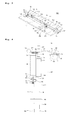
- a head alignment assembly 100 includes a first handle 124 and a second handle 104 exposed outside of the head section, as illustrated in FIGS. 1 and 2 .
- a head alignment assembly 100 includes a first handle 124 and a second handle 104 exposed outside of the head section, as illustrated in FIGS. 1 and 2 .
- Such a head alignment assembly 100 includes a base plate 102 to which the head unit 10 is fixed to be exposed downward by a first head support block 132 and a second head support block 134, a first fine adjustment section for allowing a displacement of the first head support block 132 in a longitudinal direction of the head unit 10, and a second fine adjustment section for allowing the displacement of the second head support block 134 in a transverse direction orthogonal to the longitudinal direction of the head unit 10.
- a plurality of head units 10 may be mounted on the base plate 102, and slits of a number equal to the head units 10 for the head units 10 to be exposed downward of the base plate 102 are formed on the base plate 102. Accordingly, when the plurality of head units 10 are disposed in parallel on the base plate 102, head alignment assemblies 100 of a number equal to the number of the head units 10 are disposed in parallel.
- the first head support block 132 and the second head support block 134 are installed in the slit, and the head unit 10 is fixed integrally to the first head support block 132 and the second head support block 134. Therefore, the displacement of the head unit 10 is made by the shifting of the first head support block 132 and the second head support block 134.
- the first fine adjustment section includes a first notch 133 formed on the first head support block 132 for allowing the displacement of the head unit 10 in the longitudinal direction thereof, a first push rod 126 supported by fixed guides 108, 110 and 112 fixed on the base plate 102, the first handle 124 fixed to one end of the first push rod 126 so as to move the first push rod 126 in the longitudinal direction, an integral push ring 128 of which one end is formed integrally with the other end of the first push rod 126 and the other end contacts the first notch 133, and a fixed pin 130 inserted into the integral push ring 128 to be fixed on the base plate 102.
- a lower end of the fixed pin 130 is fixed on the base plate 102 to protrude upward and an upper portion thereof is inserted into the integral push ring 128 fixed to the other end portion of the first push rod 126. Accordingly, the moving length of the first push rod 126 in the longitudinal direction thereof is limited by the fixed pin 130 within the length of the slot of the integral push ring 128 formed integrally therein.
- the width of the slot formed inside of the integral push ring 128 is formed wider than the diameter of the fixed pin 130 to provide a slight interval for the integral push ring 128.
- This interval defines an offset section between the first head support block 132 and the first push rod 126 when the first push rod 126 moves in the longitudinal direction thereof, so that it can provide a clearance to enable the head unit 10 to change position during the fine adjustment by the second fine adjustment section.
- the internal slit of the integral push ring 128 be formed lengthwise in the longitudinal direction, and the fixed pin 130 have a cross section shape (for example, a rectangular shape) in contact with both sidewalls of the internal slit, so that the integral push ring 128 can move only vertically to the fixed pin 130.
- the first head support block 132 includes the first notch 133 that contacts the outer periphery of the integral push ring 128.
- the first notch 133 is formed in substantially a "V" shape and the other end of the integral push ring 128 is formed in an elliptical shape, so that they make two-point contact. Therefore, left and right movement of the first head support block 132 is prevented, and the central axis of the integral push ring 128 normally coincides with the center of the first notch 133 so as to make it move only in the forward and backward direction (the longitudinal direction of the head 10).
- a female screw (not shown) is formed on an inner wall of the first handle 124 and a male screw (not shown) is formed on an outer surface of the first push rod 126.
- the female screw of the first handle 124 and the male screw of the first push rod 126 are screwed into each other. Therefore, if the first handle 124 rotates, the first push rod 126 moves forward or backward in the longitudinal direction thereof.
- the first push rod 126 includes a first support section so as to press the first push rod 126 to be retreated in the longitudinal direction (to be moved in the direction of the first handle 124).
- the first support section illustrates a first compression spring 123 mounted on the first push rod 126.
- One end of the first compression spring 123 is supported by a first spring seat portion 125 formed integrally on the first push rod 126, and the other end thereof is supported by a fixed guide 112.
- an axial force normally acts on the first handle 124 by an elastic force of the first compression spring 123, so that backlash generated from the screwed portion inside of the first handle 124 is removed. Therefore, so called a backlash phenomenon can be prevented by the first compression spring 123.
- the second fine adjustment section that shifts the second head support block 134 in the transverse direction of the head unit 10 includes a driven beam 136 formed integrally with the second head support block 134, a second push block 118 of which one end is fixed to a second push rod 106 and the other contacts the driven beam 136 so as to press the second head support block 134 in the transverse direction, the second push rod 106 supported by a plurality of fixed guides 108, 110, 112, 114, 116 and 117 fixed on the base plate 102, and the second handle 104 fixed to one end of the second push rod 106 so as to move the second push rod 106 in the longitudinal direction.
- the second push block 118 has a sloping side with a cross section of substantially triangular or trapezoidal shape. Therefore, if the second push block 118 moves forward, the driven beam 136 can be retreated by the sloping side in a direction away from the second push block 118 in the transverse direction of the head unit 10.
- the tip of the driven beam 136 is preferably rounded to prevent damage by friction with the second push block 118. At this time, the driven beam 136 comes into contact with the sloping side of the second push block 118, in a state protruding outward of the second head support block 134.
- the second push block 118 is formed integrally in the other end portion of the second push rod 106 which is disposed at a given interval with the head unit 10.
- the second push rod 106 includes a second support section so as to press the second push rod 106 to be retreated in the longitudinal direction (to be moved in the direction of the second handle 104).
- the second support section illustrates a second compression spring 120 mounted on the second push rod 106.
- One end of the second compression spring 120 is supported by a second spring seat portion 122 formed integrally on the second push rod 106, and the other end thereof is supported by a fixed guide 116.
- the axial force normally acts on the second handle 104 by the elastic force of the second compression spring 120, so that backlash generated from the screwed portion inside of the second handle 104 is removed. Therefore, the backlash phenomenon can be prevented by the second compression spring 120.
- the first and second support sections are not limited to the ones illustrated in the embodiments of the present invention, but a variety of modifications are possible by applying the techniques known in the art.
- the second head support block 134 includes a first reaction force member 138 and a second reaction force member 142.
- the second reaction force member 142 opposed to the second push block 118 applies a reaction force to the second head support block 134 in a direction opposite to the press direction of the second push block 118, and the first reaction force member 138 opposed to the second head support block 134 in the longitudinal direction applies a reaction force to the second head support block 134 in a direction orthogonal to the second reaction force member 142.
- Springs (not shown) for applying the reaction force are installed inside of the first reaction force member 138 and the second reaction force member 142, and a first reaction force protrusion 140 and a second reaction force protrusion 144 are coupled to the end portions of the springs.
- first reaction force member 138 and the second reaction force member 142 provide the reaction force respectively against the pressing force applied to the first head support block 132 and the second head support block 134 by the first handle 124 and the second handle 104, so that it is possible to hold an adjusted position of the head unit 10.
- the head alignment assembly 100 has a configuration basically as described above. Hereinafter, the process of fine adjustment of the head unit 10 by the head alignment assembly 100 having such a configuration will be described.
- the image for fine-adjustment is printed by operating the printer for fine adjustment and the printed image is photographed by a camera, and then a deviation of the head unit 10 deviating from the reference position is measured by comparing the photographed image and the stored image. After that, based on the measured deviation, the operator corrects the head unit 10 by rotating the first handle 124 and the second handle 104.
- the image is printed again, and the printed image is photographed by the camera, and then the deviation of the head unit 10 deviating from the reference position is measured again by comparing the photographed image and the stored image. After that, based on the measured deviation, the moving direction and moving amount of the first push rod 126 and the second push rod 106 by the first handle 124 and the second handle 104 are checked again.
- a locking device is additionally installed on the first handle 124 and second handle 104, it is preferable to suppress the deviation generated in the head unit 10 by preventing the rotation of the first and second handles 124 and 104 by the locking device after completing fine adjustment.
- the head alignment assembly 101 is basically the same as the head alignment assembly 100 of the first embodiment.
- the first reaction force member 138 and the second reaction force member 142 are replaced by a slope reaction force member 150, and a separate push ring 158 is employed instead of the integral push ring 128, so that the separate push ring 158 is indirectly pressed through a first push block 154 formed integrally with the first push rod 126.
- the positions and structures of the first and second support sections are different, and a guide slot 103 formed so as to guide the second push block 118 is additionally provided.
- the slope reaction force member 150 by integrating the first reaction force member 138 and the second reaction force member 142 of the head alignment assembly 100 of the first embodiment into one mechanism by pressing the corner of the second head support block 134 in diagonal direction. Further, for this, it is preferable that a seat portion where the end portion of a diagonal reaction force protrusion 152 of the slope reaction force member 150 comes into contact be formed on the corner of the second head support block 134.
- first push block 154 is formed integrally with one end of the first push rod 126, and the other end thereof is provided with a second notch 156 corresponding to the first notch 133.
- One end of the separate push ring 158 contacts the second notch 156 of the first push block 154 and the other end thereof contacts the first notch 133 of the first head support block 132. Accordingly, both ends of the separate push ring 158 make two-point contacts respectively with the first notch 133 and the second notch 156, so that the central axis of the separate push ring 158 normally coincides with the central axes of the first notch 133 and the second notch 156.
- the moving length of the separate push ring 158 in the longitudinal direction is limited within a predetermined range (that is, the length of the internal slot) by the fixed pin 130. Accordingly, the first push block 154 formed integrally with the first push rod 126 by forward movement of the first push rod 126 moves in the longitudinal direction. As a result, the separate push ring 158 is pressed to be moved. In addition, the first head support block 132 may be pressed by the separate push ring 158 to move in the longitudinal direction. On the other hand, if the first push rod 126 moves backward, the first head support block 132 is retreated by the slope reaction force member 150.
- first and second support sections may be one short first compression spring 153 and one short second compression spring 151.
- the first compression spring 153 is mounted on the first push rod 126 between the first push block 154 and the fixed guide 112
- the second compression spring 151 is mounted on the second push rod 106 between the second push block 118 and the fixed guide 116. Accordingly, it is possible to hold the positions of the first push rod 126 and the second push rod 106 by the support of the first and second compression springs against the reaction force of the slope reaction force member 150.
- the second push block 118 has one side formed of a plane parallel to the longitudinal direction of the second push rod 106, and a guide slot 103 that contacts the plane of the second push block 118 is formed on the base plate 102.
- the second push block 118 is supported by the guide slot 103, so it is possible to prevent deformation of the second push rod 106 due to the reaction force of the slope reaction force member 150 acting continuously through the driven beam 136.
- the head alignment assembly 105 is basically the same as the head alignment assembly 100 of the first embodiment. However, compared to the first embodiment, the head alignment assembly 105 includes an eccentric bearing 172 installed to support the second push block 118, a second support section 160 installed to support and press the second push rod 106, a coupler 174 connecting the first handle 124 and the first push rod 126 and a coupler 180 connecting the second handle 104 and the second push rod 106.
- a driven beam 184 separated from a second head support block 182 is employed instead of the driven beam 136 formed integrally on the second head support block 134.
- the eccentric bearing 172 contacts a surface opposite to the sloping side of the second push block 118 in contact with the driven beam 184. Accordingly, the eccentric bearing 172 plays a role of preventing the deformation of the second push rod 106 generated by the first and second reaction force members 138 and 142, likewise with the guide slot 103.
- the eccentric bearing 172 is rotatably mounted on an eccentric bolt 170 fixed on the base plate 102. Accordingly, it is possible to change the position of the eccentric bearing 172 by rotating the eccentric bolt 170. Therefore, it is possible to adjust the fine interval between the second push block 118 and the eccentric bearing 172 by the eccentric bolt 170.
- the second head support block 182 is formed in substantially an 'L' letter shape, as illustrated in FIG. 5 , and the driven beam 184 is installed in the bent portion thereof.
- the driven beam 184 is a substantially elliptical ring having a slit therein, and an upper portion of a driven beam pin 186 of which a lower end is fixed on the base plate 102 is inserted into the slit.
- the driven beam pin 186 has a cross section of substantially rectangular or square shape so as to guide the driven beam 184 to move in a straight line.
- one end of the driven beam 184 comes into contact with the second head support block 182, and the other end of the driven beam 184 comes into contact with the sloping side of the second push block 118.
- a driven bearing 137 may be installed at the end portion of the driven beam 184 so as to provide a smooth contact between the second push block 118 and the driven beam 184.
- the second support section 160 includes a support casing 161 having a space therein, and a second compression spring 162 which is installed in the support casing 161 to press one end of the second push rod 106 inserted into the casing.
- an adjustment bolt 168 for adjusting the reaction force of the second compression spring 162 may mounted on the support casing 161 on the opposite side of the second push rod 106.
- washers 164 and 166 are arranged at both ends of the second compression spring 162 to prevent the second compression spring 162 from being rotated by the rotation of the adjustment bolt 168.
- the outside ends of the washers 164 and 166 are in contact with one end of the second push rod 106 and the adjustment bolt 168 respectively.
- the couplers 174 and 180 are used for the case that the handle axes 107 and 127 of the first and second handles 104 and 124 are protruded lengthwise. That is, the coupler 174 connects the second push rod 106 and the handle axis 107, and the coupler 180 connects the first push rod 126 and the handle axis 127.
- the couplers 174 and 180 connect one end of the push rod and one end of the handle axes by coupling bolts 176 and 178.
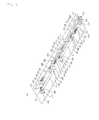
- the head alignment assembly 200 is basically the same as the head alignment assembly 100 of the first embodiment. However, compared to the first embodiment, when head units 12 and 14 are disposed in a row in the longitudinal direction on a base plate 202, or the distance between the central axes of two head units is so short that the space is not enough for the first and second push rods to be inserted, first and second push rods 252 and 276; and 206 and 230 are installed in parallel with each other on different levels.
- the head alignment assembly 200 includes two first head support blocks 262 and 286, two second head support blocks 266 and 290, a first fine adjustment section for allowing the displacement of the head support blocks 262 and 286 in the longitudinal direction of the head unit 10, and a second fine adjustment section for allowing the displacement of the second head support blocks 266 and 290 in the transverse direction orthogonal to the longitudinal direction of the head units 12 and 14.
- the first and second push rods 252 and 276; and 206 and 230 are supported by fixed guides 208, 210, 212, 214, 216, 218, 220, 222, 224, and 226 which are installed on the base plate 202 in parallel with each other on different levels.
- Integral push rings 258 and 282 have height different from each other so as to be fixed integrally to the first push rods 252 and 276 with different heights. That is, the height of the integral push ring 258 on the side close to the first handles 250 and 274 is lower than the height the integral push ring 282 on the far side.
- the second push blocks 236 and 242 have the thickness different so as to be fixed integrally to the second push rods 206 and 230 with different heights. That is, the thickness of the second push block 236 close to the second handles 204 and 228 is smaller than the thickness of the second push block 242 on the far side.
- first reaction force members 270 and 294, second reaction force members 272 and 296, first compression springs 256 and 280, first spring seat portions 254 and 278, second compression springs 234 and 240, second spring seat portions 232 and 238, driven beams 268 and 292, and the second head support blocks 266 and 290 is the same as the first embodiment, so detailed description thereof is omitted.
- first head support blocks 262 and 286 it is also possible to increase the thickness of the first head support block 286 disposed far from the first handles 250 and 274, as illustrated in FIG. 6 .
- the shape of the first notches 264 and 288 formed on the first head support blocks 262 and 286 is the same as the first embodiment.
Landscapes
- Ink Jet (AREA)
Applications Claiming Priority (3)
| Application Number | Priority Date | Filing Date | Title |
|---|---|---|---|
| KR20120024490 | 2012-03-09 | ||
| KR1020120035581A KR101183230B1 (ko) | 2012-03-09 | 2012-04-05 | 헤드 정렬장치 |
| PCT/KR2012/002855 WO2013133475A1 (ko) | 2012-03-09 | 2012-04-16 | 헤드 정렬장치 |
Publications (3)
| Publication Number | Publication Date |
|---|---|
| EP2823966A1 true EP2823966A1 (de) | 2015-01-14 |
| EP2823966A4 EP2823966A4 (de) | 2016-05-18 |
| EP2823966B1 EP2823966B1 (de) | 2018-12-26 |
Family
ID=47113602
Family Applications (1)
| Application Number | Title | Priority Date | Filing Date |
|---|---|---|---|
| EP12870675.1A Active EP2823966B1 (de) | 2012-03-09 | 2012-04-16 | Kopfausrichtungsvorrichtung |
Country Status (6)
| Country | Link |
|---|---|
| US (1) | US8979240B2 (de) |
| EP (1) | EP2823966B1 (de) |
| JP (1) | JP5899314B2 (de) |
| KR (1) | KR101183230B1 (de) |
| CN (1) | CN103619604B (de) |
| WO (1) | WO2013133475A1 (de) |
Families Citing this family (7)
| Publication number | Priority date | Publication date | Assignee | Title |
|---|---|---|---|---|
| JP2017512681A (ja) * | 2014-03-26 | 2017-05-25 | オセ−テクノロジーズ ビーブイ | 複数のプリントヘッドユニットの取付構造 |
| KR101668396B1 (ko) * | 2014-09-26 | 2016-10-28 | (주) 평 안 | 프린터 헤드 정렬 장치 |
| DE102016209945A1 (de) * | 2015-07-07 | 2017-01-12 | Heidelberger Druckmaschinen Ag | Drucker |
| EP3539791B1 (de) * | 2018-03-16 | 2023-01-18 | Heidelberger Druckmaschinen AG | Druckbalken für inkjet |
| CN109382623B (zh) * | 2018-11-21 | 2024-03-15 | 苏州市冯氏智能科技有限公司 | 一种应用于工程机械钣金零件的焊接定位工装 |
| KR102589069B1 (ko) * | 2021-08-24 | 2023-10-16 | 이노6 주식회사 | 피동체 조절 장치 |
| KR102570671B1 (ko) * | 2023-02-21 | 2023-08-25 | 주식회사 딜리 | 싱글패스 잉크젯 프린터용 헤드 자동 정렬시스템 |
Family Cites Families (18)
| Publication number | Priority date | Publication date | Assignee | Title |
|---|---|---|---|---|
| US5917528A (en) * | 1996-09-05 | 1999-06-29 | Tektronix, Inc. | Solid ink stick supply apparatus and method |
| JP2002292907A (ja) * | 2001-03-30 | 2002-10-09 | Brother Ind Ltd | カラーインクジェット記録装置 |
| CN1377781A (zh) * | 2002-04-28 | 2002-11-06 | 和近建 | 阵列针式滚筒打印机设计原理 |
| JP4258190B2 (ja) | 2002-08-30 | 2009-04-30 | コニカミノルタホールディングス株式会社 | 記録ヘッドの取付構造、プリンタ及び記録ヘッドの取付方法 |
| WO2004028816A1 (ja) * | 2002-09-30 | 2004-04-08 | Sony Corporation | 電子部品位置合わせ方法及びその装置 |
| KR100848162B1 (ko) * | 2004-01-19 | 2008-07-23 | 삼성전자주식회사 | 잉크젯 프린팅 장치 및 헤드위치 조절방법 |
| KR100662564B1 (ko) * | 2004-08-19 | 2006-12-28 | 삼성전자주식회사 | 얼라인장치 |
| CN1769974A (zh) * | 2004-10-14 | 2006-05-10 | 三菱丽阳株式会社 | 绘图装置和绘图方法 |
| US7556334B2 (en) * | 2004-11-04 | 2009-07-07 | Applied Materials, Inc. | Methods and apparatus for aligning print heads |
| KR100811231B1 (ko) * | 2006-08-16 | 2008-03-07 | 한양대학교 산학협력단 | 잉크젯 프린팅 장비의 헤드 정렬 장치 |
| JP2008062583A (ja) * | 2006-09-08 | 2008-03-21 | Olympus Corp | 記録ヘッド位置調整構造、記録ヘッド位置調整治具 |
| JP5010216B2 (ja) | 2006-09-08 | 2012-08-29 | 株式会社ミマキエンジニアリング | プリンタ装置のプリンタヘッド |
| ES2307436B1 (es) * | 2007-05-14 | 2009-10-02 | Jesus Francisco Barberan Latorre | Sistema de posicionamiento de los cabezales en impresoras. |
| KR20080105670A (ko) * | 2007-05-31 | 2008-12-04 | 주식회사 케이씨텍 | 잉크젯 헤드의 정렬 장치 및 방법 |
| JP2009190188A (ja) * | 2008-02-12 | 2009-08-27 | Sii Printek Inc | インクジェットヘッド及びインクジェット記録装置 |
| JP5102108B2 (ja) * | 2008-05-27 | 2012-12-19 | 大日本スクリーン製造株式会社 | インクジェットヘッド、ヘッドユニットおよび印刷装置 |
| JP4862904B2 (ja) * | 2009-03-11 | 2012-01-25 | ブラザー工業株式会社 | ヘッド位置調整機構 |
| US20110149000A1 (en) * | 2009-12-23 | 2011-06-23 | Ulvac, Inc. | Inkjet printhead module with adjustable alignment |
-
2012
- 2012-04-05 KR KR1020120035581A patent/KR101183230B1/ko active Active
- 2012-04-16 WO PCT/KR2012/002855 patent/WO2013133475A1/ko not_active Ceased
- 2012-04-16 JP JP2014516886A patent/JP5899314B2/ja active Active
- 2012-04-16 CN CN201280030507.0A patent/CN103619604B/zh active Active
- 2012-04-16 EP EP12870675.1A patent/EP2823966B1/de active Active
- 2012-04-16 US US14/127,865 patent/US8979240B2/en active Active
Also Published As
| Publication number | Publication date |
|---|---|
| WO2013133475A1 (ko) | 2013-09-12 |
| EP2823966A4 (de) | 2016-05-18 |
| EP2823966B1 (de) | 2018-12-26 |
| KR101183230B1 (ko) | 2012-09-14 |
| US8979240B2 (en) | 2015-03-17 |
| JP2014522746A (ja) | 2014-09-08 |
| US20140160201A1 (en) | 2014-06-12 |
| CN103619604B (zh) | 2015-10-07 |
| CN103619604A (zh) | 2014-03-05 |
| JP5899314B2 (ja) | 2016-04-06 |
Similar Documents
| Publication | Publication Date | Title |
|---|---|---|
| EP2823966A1 (de) | Kopfausrichtungsvorrichtung | |
| US7992469B2 (en) | Screw feeding device in continuous screw driving tool | |
| US10478363B2 (en) | Clamping claw for mounting on a sliding rail of an operating table | |
| EP3195980B1 (de) | Kippklemme | |
| JP5001201B2 (ja) | コネクタ装置及びコネクタ装置の接続方法 | |
| US8056386B2 (en) | Pin bending device | |
| JP2024507306A (ja) | 溶接治具及び挟持方法 | |
| KR102013175B1 (ko) | 교체 가능한 더블타입 프로브 핀 | |
| US4611939A (en) | Sheet feeding device for an impact-type printer | |
| JP5638304B2 (ja) | クランプ装置 | |
| WO2023042558A1 (ja) | 有限ストロークタイプの直線案内装置 | |
| EP2918411B1 (de) | Justierung einer relativen Position eines Druckkopfs zu einem Druckstangenträgerelement | |
| KR20160086265A (ko) | 롤러 리프터 | |
| EP1976364B1 (de) | Mechanische Schnittstelle | |
| KR101959471B1 (ko) | 벤딩 장치 | |
| CN221519108U (zh) | 用于打印机的限纸装置 | |
| CN107971969A (zh) | 用于安装摄像头的工装 | |
| KR101978303B1 (ko) | 면취 가공부가 형성된 소형가이드축 직진성 교정장치 및 전수검사용 지그장치 | |
| JP4299056B2 (ja) | 圧入装置、および圧入方法 | |
| CN212123196U (zh) | 制证装置的夹具及制证装置 | |
| CN216608048U (zh) | 夹持装置 | |
| JP6087962B2 (ja) | 調節可能なプリントヘッド | |
| JP6463070B2 (ja) | クランク式駆動装置 | |
| CN213319700U (zh) | 一种定位载具 | |
| CN108393668A (zh) | 一种充电端子插针推动装置 |
Legal Events
| Date | Code | Title | Description |
|---|---|---|---|
| PUAI | Public reference made under article 153(3) epc to a published international application that has entered the european phase |
Free format text: ORIGINAL CODE: 0009012 |
|
| 17P | Request for examination filed |
Effective date: 20131205 |
|
| AK | Designated contracting states |
Kind code of ref document: A1 Designated state(s): AL AT BE BG CH CY CZ DE DK EE ES FI FR GB GR HR HU IE IS IT LI LT LU LV MC MK MT NL NO PL PT RO RS SE SI SK SM TR |
|
| AX | Request for extension of the european patent |
Extension state: BA ME |
|
| DAX | Request for extension of the european patent (deleted) | ||
| RA4 | Supplementary search report drawn up and despatched (corrected) |
Effective date: 20160414 |
|
| RIC1 | Information provided on ipc code assigned before grant |
Ipc: B41J 29/38 20060101AFI20160408BHEP Ipc: B41J 2/155 20060101ALI20160408BHEP Ipc: B41J 25/00 20060101ALI20160408BHEP Ipc: B41J 2/175 20060101ALI20160408BHEP |
|
| GRAP | Despatch of communication of intention to grant a patent |
Free format text: ORIGINAL CODE: EPIDOSNIGR1 |
|
| STAA | Information on the status of an ep patent application or granted ep patent |
Free format text: STATUS: GRANT OF PATENT IS INTENDED |
|
| INTG | Intention to grant announced |
Effective date: 20180802 |
|
| GRAS | Grant fee paid |
Free format text: ORIGINAL CODE: EPIDOSNIGR3 |
|
| GRAA | (expected) grant |
Free format text: ORIGINAL CODE: 0009210 |
|
| STAA | Information on the status of an ep patent application or granted ep patent |
Free format text: STATUS: THE PATENT HAS BEEN GRANTED |
|
| AK | Designated contracting states |
Kind code of ref document: B1 Designated state(s): AL AT BE BG CH CY CZ DE DK EE ES FI FR GB GR HR HU IE IS IT LI LT LU LV MC MK MT NL NO PL PT RO RS SE SI SK SM TR |
|
| REG | Reference to a national code |
Ref country code: GB Ref legal event code: FG4D |
|
| REG | Reference to a national code |
Ref country code: CH Ref legal event code: EP |
|
| REG | Reference to a national code |
Ref country code: AT Ref legal event code: REF Ref document number: 1080865 Country of ref document: AT Kind code of ref document: T Effective date: 20190115 |
|
| REG | Reference to a national code |
Ref country code: DE Ref legal event code: R096 Ref document number: 602012055295 Country of ref document: DE |
|
| REG | Reference to a national code |
Ref country code: IE Ref legal event code: FG4D |
|
| PG25 | Lapsed in a contracting state [announced via postgrant information from national office to epo] |
Ref country code: FI Free format text: LAPSE BECAUSE OF FAILURE TO SUBMIT A TRANSLATION OF THE DESCRIPTION OR TO PAY THE FEE WITHIN THE PRESCRIBED TIME-LIMIT Effective date: 20181226 Ref country code: HR Free format text: LAPSE BECAUSE OF FAILURE TO SUBMIT A TRANSLATION OF THE DESCRIPTION OR TO PAY THE FEE WITHIN THE PRESCRIBED TIME-LIMIT Effective date: 20181226 Ref country code: LT Free format text: LAPSE BECAUSE OF FAILURE TO SUBMIT A TRANSLATION OF THE DESCRIPTION OR TO PAY THE FEE WITHIN THE PRESCRIBED TIME-LIMIT Effective date: 20181226 Ref country code: LV Free format text: LAPSE BECAUSE OF FAILURE TO SUBMIT A TRANSLATION OF THE DESCRIPTION OR TO PAY THE FEE WITHIN THE PRESCRIBED TIME-LIMIT Effective date: 20181226 Ref country code: NO Free format text: LAPSE BECAUSE OF FAILURE TO SUBMIT A TRANSLATION OF THE DESCRIPTION OR TO PAY THE FEE WITHIN THE PRESCRIBED TIME-LIMIT Effective date: 20190326 Ref country code: BG Free format text: LAPSE BECAUSE OF FAILURE TO SUBMIT A TRANSLATION OF THE DESCRIPTION OR TO PAY THE FEE WITHIN THE PRESCRIBED TIME-LIMIT Effective date: 20190326 |
|
| REG | Reference to a national code |
Ref country code: NL Ref legal event code: MP Effective date: 20181226 |
|
| REG | Reference to a national code |
Ref country code: LT Ref legal event code: MG4D |
|
| PG25 | Lapsed in a contracting state [announced via postgrant information from national office to epo] |
Ref country code: AL Free format text: LAPSE BECAUSE OF FAILURE TO SUBMIT A TRANSLATION OF THE DESCRIPTION OR TO PAY THE FEE WITHIN THE PRESCRIBED TIME-LIMIT Effective date: 20181226 Ref country code: SE Free format text: LAPSE BECAUSE OF FAILURE TO SUBMIT A TRANSLATION OF THE DESCRIPTION OR TO PAY THE FEE WITHIN THE PRESCRIBED TIME-LIMIT Effective date: 20181226 Ref country code: GR Free format text: LAPSE BECAUSE OF FAILURE TO SUBMIT A TRANSLATION OF THE DESCRIPTION OR TO PAY THE FEE WITHIN THE PRESCRIBED TIME-LIMIT Effective date: 20190327 Ref country code: RS Free format text: LAPSE BECAUSE OF FAILURE TO SUBMIT A TRANSLATION OF THE DESCRIPTION OR TO PAY THE FEE WITHIN THE PRESCRIBED TIME-LIMIT Effective date: 20181226 |
|
| REG | Reference to a national code |
Ref country code: AT Ref legal event code: MK05 Ref document number: 1080865 Country of ref document: AT Kind code of ref document: T Effective date: 20181226 |
|
| PG25 | Lapsed in a contracting state [announced via postgrant information from national office to epo] |
Ref country code: NL Free format text: LAPSE BECAUSE OF FAILURE TO SUBMIT A TRANSLATION OF THE DESCRIPTION OR TO PAY THE FEE WITHIN THE PRESCRIBED TIME-LIMIT Effective date: 20181226 |
|
| PG25 | Lapsed in a contracting state [announced via postgrant information from national office to epo] |
Ref country code: PT Free format text: LAPSE BECAUSE OF FAILURE TO SUBMIT A TRANSLATION OF THE DESCRIPTION OR TO PAY THE FEE WITHIN THE PRESCRIBED TIME-LIMIT Effective date: 20190426 Ref country code: CZ Free format text: LAPSE BECAUSE OF FAILURE TO SUBMIT A TRANSLATION OF THE DESCRIPTION OR TO PAY THE FEE WITHIN THE PRESCRIBED TIME-LIMIT Effective date: 20181226 Ref country code: ES Free format text: LAPSE BECAUSE OF FAILURE TO SUBMIT A TRANSLATION OF THE DESCRIPTION OR TO PAY THE FEE WITHIN THE PRESCRIBED TIME-LIMIT Effective date: 20181226 Ref country code: PL Free format text: LAPSE BECAUSE OF FAILURE TO SUBMIT A TRANSLATION OF THE DESCRIPTION OR TO PAY THE FEE WITHIN THE PRESCRIBED TIME-LIMIT Effective date: 20181226 |
|
| PG25 | Lapsed in a contracting state [announced via postgrant information from national office to epo] |
Ref country code: SM Free format text: LAPSE BECAUSE OF FAILURE TO SUBMIT A TRANSLATION OF THE DESCRIPTION OR TO PAY THE FEE WITHIN THE PRESCRIBED TIME-LIMIT Effective date: 20181226 Ref country code: EE Free format text: LAPSE BECAUSE OF FAILURE TO SUBMIT A TRANSLATION OF THE DESCRIPTION OR TO PAY THE FEE WITHIN THE PRESCRIBED TIME-LIMIT Effective date: 20181226 Ref country code: IS Free format text: LAPSE BECAUSE OF FAILURE TO SUBMIT A TRANSLATION OF THE DESCRIPTION OR TO PAY THE FEE WITHIN THE PRESCRIBED TIME-LIMIT Effective date: 20190426 Ref country code: SK Free format text: LAPSE BECAUSE OF FAILURE TO SUBMIT A TRANSLATION OF THE DESCRIPTION OR TO PAY THE FEE WITHIN THE PRESCRIBED TIME-LIMIT Effective date: 20181226 Ref country code: RO Free format text: LAPSE BECAUSE OF FAILURE TO SUBMIT A TRANSLATION OF THE DESCRIPTION OR TO PAY THE FEE WITHIN THE PRESCRIBED TIME-LIMIT Effective date: 20181226 |
|
| REG | Reference to a national code |
Ref country code: DE Ref legal event code: R097 Ref document number: 602012055295 Country of ref document: DE |
|
| PG25 | Lapsed in a contracting state [announced via postgrant information from national office to epo] |
Ref country code: DK Free format text: LAPSE BECAUSE OF FAILURE TO SUBMIT A TRANSLATION OF THE DESCRIPTION OR TO PAY THE FEE WITHIN THE PRESCRIBED TIME-LIMIT Effective date: 20181226 Ref country code: AT Free format text: LAPSE BECAUSE OF FAILURE TO SUBMIT A TRANSLATION OF THE DESCRIPTION OR TO PAY THE FEE WITHIN THE PRESCRIBED TIME-LIMIT Effective date: 20181226 |
|
| PLBE | No opposition filed within time limit |
Free format text: ORIGINAL CODE: 0009261 |
|
| STAA | Information on the status of an ep patent application or granted ep patent |
Free format text: STATUS: NO OPPOSITION FILED WITHIN TIME LIMIT |
|
| REG | Reference to a national code |
Ref country code: CH Ref legal event code: PL |
|
| 26N | No opposition filed |
Effective date: 20190927 |
|
| PG25 | Lapsed in a contracting state [announced via postgrant information from national office to epo] |
Ref country code: LU Free format text: LAPSE BECAUSE OF NON-PAYMENT OF DUE FEES Effective date: 20190416 Ref country code: MC Free format text: LAPSE BECAUSE OF FAILURE TO SUBMIT A TRANSLATION OF THE DESCRIPTION OR TO PAY THE FEE WITHIN THE PRESCRIBED TIME-LIMIT Effective date: 20181226 |
|
| PG25 | Lapsed in a contracting state [announced via postgrant information from national office to epo] |
Ref country code: LI Free format text: LAPSE BECAUSE OF NON-PAYMENT OF DUE FEES Effective date: 20190430 Ref country code: CH Free format text: LAPSE BECAUSE OF NON-PAYMENT OF DUE FEES Effective date: 20190430 |
|
| PG25 | Lapsed in a contracting state [announced via postgrant information from national office to epo] |
Ref country code: FR Free format text: LAPSE BECAUSE OF NON-PAYMENT OF DUE FEES Effective date: 20190430 Ref country code: SI Free format text: LAPSE BECAUSE OF FAILURE TO SUBMIT A TRANSLATION OF THE DESCRIPTION OR TO PAY THE FEE WITHIN THE PRESCRIBED TIME-LIMIT Effective date: 20181226 |
|
| PG25 | Lapsed in a contracting state [announced via postgrant information from national office to epo] |
Ref country code: TR Free format text: LAPSE BECAUSE OF FAILURE TO SUBMIT A TRANSLATION OF THE DESCRIPTION OR TO PAY THE FEE WITHIN THE PRESCRIBED TIME-LIMIT Effective date: 20181226 |
|
| PG25 | Lapsed in a contracting state [announced via postgrant information from national office to epo] |
Ref country code: IE Free format text: LAPSE BECAUSE OF NON-PAYMENT OF DUE FEES Effective date: 20190416 |
|
| PG25 | Lapsed in a contracting state [announced via postgrant information from national office to epo] |
Ref country code: CY Free format text: LAPSE BECAUSE OF FAILURE TO SUBMIT A TRANSLATION OF THE DESCRIPTION OR TO PAY THE FEE WITHIN THE PRESCRIBED TIME-LIMIT Effective date: 20181226 |
|
| PG25 | Lapsed in a contracting state [announced via postgrant information from national office to epo] |
Ref country code: MT Free format text: LAPSE BECAUSE OF FAILURE TO SUBMIT A TRANSLATION OF THE DESCRIPTION OR TO PAY THE FEE WITHIN THE PRESCRIBED TIME-LIMIT Effective date: 20181226 Ref country code: HU Free format text: LAPSE BECAUSE OF FAILURE TO SUBMIT A TRANSLATION OF THE DESCRIPTION OR TO PAY THE FEE WITHIN THE PRESCRIBED TIME-LIMIT; INVALID AB INITIO Effective date: 20120416 |
|
| PG25 | Lapsed in a contracting state [announced via postgrant information from national office to epo] |
Ref country code: MK Free format text: LAPSE BECAUSE OF FAILURE TO SUBMIT A TRANSLATION OF THE DESCRIPTION OR TO PAY THE FEE WITHIN THE PRESCRIBED TIME-LIMIT Effective date: 20181226 |
|
| PGFP | Annual fee paid to national office [announced via postgrant information from national office to epo] |
Ref country code: DE Payment date: 20250429 Year of fee payment: 14 |
|
| PGFP | Annual fee paid to national office [announced via postgrant information from national office to epo] |
Ref country code: IT Payment date: 20250430 Year of fee payment: 14 Ref country code: BE Payment date: 20250422 Year of fee payment: 14 |
|
| PGFP | Annual fee paid to national office [announced via postgrant information from national office to epo] |
Ref country code: GB Payment date: 20260324 Year of fee payment: 15 |