EP2823528B1 - Redox flow battery for hydrogen generation - Google Patents
Redox flow battery for hydrogen generation Download PDFInfo
- Publication number
- EP2823528B1 EP2823528B1 EP13707009.0A EP13707009A EP2823528B1 EP 2823528 B1 EP2823528 B1 EP 2823528B1 EP 13707009 A EP13707009 A EP 13707009A EP 2823528 B1 EP2823528 B1 EP 2823528B1
- Authority
- EP
- European Patent Office
- Prior art keywords
- electrolyte
- electrodes
- redox
- hydrogen
- electrolytes
- Prior art date
- Legal status (The legal status is an assumption and is not a legal conclusion. Google has not performed a legal analysis and makes no representation as to the accuracy of the status listed.)
- Active
Links
Images


Classifications
-
- H—ELECTRICITY
- H01—ELECTRIC ELEMENTS
- H01M—PROCESSES OR MEANS, e.g. BATTERIES, FOR THE DIRECT CONVERSION OF CHEMICAL ENERGY INTO ELECTRICAL ENERGY
- H01M8/00—Fuel cells; Manufacture thereof
- H01M8/06—Combination of fuel cells with means for production of reactants or for treatment of residues
- H01M8/0606—Combination of fuel cells with means for production of reactants or for treatment of residues with means for production of gaseous reactants
-
- H—ELECTRICITY
- H01—ELECTRIC ELEMENTS
- H01M—PROCESSES OR MEANS, e.g. BATTERIES, FOR THE DIRECT CONVERSION OF CHEMICAL ENERGY INTO ELECTRICAL ENERGY
- H01M8/00—Fuel cells; Manufacture thereof
- H01M8/20—Indirect fuel cells, e.g. fuel cells with redox couple being irreversible
-
- C—CHEMISTRY; METALLURGY
- C25—ELECTROLYTIC OR ELECTROPHORETIC PROCESSES; APPARATUS THEREFOR
- C25B—ELECTROLYTIC OR ELECTROPHORETIC PROCESSES FOR THE PRODUCTION OF COMPOUNDS OR NON-METALS; APPARATUS THEREFOR
- C25B1/00—Electrolytic production of inorganic compounds or non-metals
- C25B1/01—Products
- C25B1/02—Hydrogen or oxygen
- C25B1/04—Hydrogen or oxygen by electrolysis of water
-
- C—CHEMISTRY; METALLURGY
- C25—ELECTROLYTIC OR ELECTROPHORETIC PROCESSES; APPARATUS THEREFOR
- C25B—ELECTROLYTIC OR ELECTROPHORETIC PROCESSES FOR THE PRODUCTION OF COMPOUNDS OR NON-METALS; APPARATUS THEREFOR
- C25B1/00—Electrolytic production of inorganic compounds or non-metals
- C25B1/50—Processes
-
- C—CHEMISTRY; METALLURGY
- C25—ELECTROLYTIC OR ELECTROPHORETIC PROCESSES; APPARATUS THEREFOR
- C25B—ELECTROLYTIC OR ELECTROPHORETIC PROCESSES FOR THE PRODUCTION OF COMPOUNDS OR NON-METALS; APPARATUS THEREFOR
- C25B15/00—Operating or servicing cells
- C25B15/08—Supplying or removing reactants or electrolytes; Regeneration of electrolytes
-
- H—ELECTRICITY
- H01—ELECTRIC ELEMENTS
- H01M—PROCESSES OR MEANS, e.g. BATTERIES, FOR THE DIRECT CONVERSION OF CHEMICAL ENERGY INTO ELECTRICAL ENERGY
- H01M4/00—Electrodes
- H01M4/86—Inert electrodes with catalytic activity, e.g. for fuel cells
- H01M4/8605—Porous electrodes
- H01M4/8615—Bifunctional electrodes for rechargeable cells
-
- H—ELECTRICITY
- H01—ELECTRIC ELEMENTS
- H01M—PROCESSES OR MEANS, e.g. BATTERIES, FOR THE DIRECT CONVERSION OF CHEMICAL ENERGY INTO ELECTRICAL ENERGY
- H01M4/00—Electrodes
- H01M4/86—Inert electrodes with catalytic activity, e.g. for fuel cells
- H01M4/8605—Porous electrodes
- H01M4/8626—Porous electrodes characterised by the form
- H01M4/8631—Bipolar electrodes
-
- H—ELECTRICITY
- H01—ELECTRIC ELEMENTS
- H01M—PROCESSES OR MEANS, e.g. BATTERIES, FOR THE DIRECT CONVERSION OF CHEMICAL ENERGY INTO ELECTRICAL ENERGY
- H01M8/00—Fuel cells; Manufacture thereof
- H01M8/04—Auxiliary arrangements, e.g. for control of pressure or for circulation of fluids
- H01M8/04082—Arrangements for control of reactant parameters, e.g. pressure or concentration
- H01M8/04201—Reactant storage and supply, e.g. means for feeding, pipes
- H01M8/04208—Cartridges, cryogenic media or cryogenic reservoirs
-
- H—ELECTRICITY
- H01—ELECTRIC ELEMENTS
- H01M—PROCESSES OR MEANS, e.g. BATTERIES, FOR THE DIRECT CONVERSION OF CHEMICAL ENERGY INTO ELECTRICAL ENERGY
- H01M8/00—Fuel cells; Manufacture thereof
- H01M8/06—Combination of fuel cells with means for production of reactants or for treatment of residues
- H01M8/0606—Combination of fuel cells with means for production of reactants or for treatment of residues with means for production of gaseous reactants
- H01M8/0656—Combination of fuel cells with means for production of reactants or for treatment of residues with means for production of gaseous reactants by electrochemical means
-
- H—ELECTRICITY
- H01—ELECTRIC ELEMENTS
- H01M—PROCESSES OR MEANS, e.g. BATTERIES, FOR THE DIRECT CONVERSION OF CHEMICAL ENERGY INTO ELECTRICAL ENERGY
- H01M8/00—Fuel cells; Manufacture thereof
- H01M8/06—Combination of fuel cells with means for production of reactants or for treatment of residues
- H01M8/0693—Treatment of the electrolyte residue, e.g. reconcentrating
-
- H—ELECTRICITY
- H01—ELECTRIC ELEMENTS
- H01M—PROCESSES OR MEANS, e.g. BATTERIES, FOR THE DIRECT CONVERSION OF CHEMICAL ENERGY INTO ELECTRICAL ENERGY
- H01M8/00—Fuel cells; Manufacture thereof
- H01M8/08—Fuel cells with aqueous electrolytes
-
- H—ELECTRICITY
- H01—ELECTRIC ELEMENTS
- H01M—PROCESSES OR MEANS, e.g. BATTERIES, FOR THE DIRECT CONVERSION OF CHEMICAL ENERGY INTO ELECTRICAL ENERGY
- H01M8/00—Fuel cells; Manufacture thereof
- H01M8/18—Regenerative fuel cells, e.g. redox flow batteries or secondary fuel cells
- H01M8/184—Regeneration by electrochemical means
- H01M8/188—Regeneration by electrochemical means by recharging of redox couples containing fluids; Redox flow type batteries
-
- H—ELECTRICITY
- H01—ELECTRIC ELEMENTS
- H01M—PROCESSES OR MEANS, e.g. BATTERIES, FOR THE DIRECT CONVERSION OF CHEMICAL ENERGY INTO ELECTRICAL ENERGY
- H01M8/00—Fuel cells; Manufacture thereof
- H01M8/22—Fuel cells in which the fuel is based on materials comprising carbon or oxygen or hydrogen and other elements; Fuel cells in which the fuel is based on materials comprising only elements other than carbon, oxygen or hydrogen
-
- H—ELECTRICITY
- H01—ELECTRIC ELEMENTS
- H01M—PROCESSES OR MEANS, e.g. BATTERIES, FOR THE DIRECT CONVERSION OF CHEMICAL ENERGY INTO ELECTRICAL ENERGY
- H01M4/00—Electrodes
- H01M4/86—Inert electrodes with catalytic activity, e.g. for fuel cells
- H01M4/96—Carbon-based electrodes
-
- Y—GENERAL TAGGING OF NEW TECHNOLOGICAL DEVELOPMENTS; GENERAL TAGGING OF CROSS-SECTIONAL TECHNOLOGIES SPANNING OVER SEVERAL SECTIONS OF THE IPC; TECHNICAL SUBJECTS COVERED BY FORMER USPC CROSS-REFERENCE ART COLLECTIONS [XRACs] AND DIGESTS
- Y02—TECHNOLOGIES OR APPLICATIONS FOR MITIGATION OR ADAPTATION AGAINST CLIMATE CHANGE
- Y02E—REDUCTION OF GREENHOUSE GAS [GHG] EMISSIONS, RELATED TO ENERGY GENERATION, TRANSMISSION OR DISTRIBUTION
- Y02E60/00—Enabling technologies; Technologies with a potential or indirect contribution to GHG emissions mitigation
- Y02E60/30—Hydrogen technology
- Y02E60/50—Fuel cells
-
- Y—GENERAL TAGGING OF NEW TECHNOLOGICAL DEVELOPMENTS; GENERAL TAGGING OF CROSS-SECTIONAL TECHNOLOGIES SPANNING OVER SEVERAL SECTIONS OF THE IPC; TECHNICAL SUBJECTS COVERED BY FORMER USPC CROSS-REFERENCE ART COLLECTIONS [XRACs] AND DIGESTS
- Y02—TECHNOLOGIES OR APPLICATIONS FOR MITIGATION OR ADAPTATION AGAINST CLIMATE CHANGE
- Y02P—CLIMATE CHANGE MITIGATION TECHNOLOGIES IN THE PRODUCTION OR PROCESSING OF GOODS
- Y02P20/00—Technologies relating to chemical industry
- Y02P20/50—Improvements relating to the production of bulk chemicals
- Y02P20/584—Recycling of catalysts
Definitions
- This invention relates to a redox flow battery system for electrical energy storage and hydrogen production.
- RFBs Redox flow batteries
- the main disadvantage of RFBs is that energy storage capacity is determined by the solubility of the actives electrolytes and that large tanks are thus usually required. They may be applied to load levelling, wind farms and photovoltaic panels [ Ponce de León, C., Fr ⁇ as-Ferrer, A., González-Garc ⁇ a, J., Szánto, D.A., and Walsh, F.C. (2006). Redox flow cells for energy conversion. Journal of Power Sources 160: 716-732 ].
- a RFB is a system in which two half-cells of the battery are each connected to a storage tank containing a solution composed of the redox species and the supporting electrolyte.
- An ion-exchange membrane separates the half-cells, whilst allowing ion transfer and electrical continuity during charging and discharging of the cell.
- the negatively polarised electrode is the cathode
- the electrolyte in which the redox species is being reduced, is termed the catholyte.
- the positive half-cell has the anode and the electrolyte termed the anolyte.
- Pumps are used to transfer electrolytes from their respective storage tanks to the electrochemical cell, and to the storage tanks again.
- the key to the system is in choosing appropriate redox species. Generally the redox couples and the electrodes are selected to achieve close-to-reversible kinetics, allowing higher voltage and energy efficiencies of the battery.
- the vanadium redox flow battery (VRFB) is a particular case, as it works with vanadium species in both half-cells: the redox couple V(III)/V(II) on the cathodic side, and the redox couple V(V)/V(IV) on the anodic side [ US patent N°4,786,567 ]. It has the advantage that cross-diffusion of cations through the membrane does not affect the cycle current efficiency, and allows for a longer battery lifetime.
- a VRFB charges when connected to an electricity source, and discharges when connected to an electrical load. The electrolytes flow in one direction through the half-cells, regardless of the process underway, yet the electrochemical reaction taking place differs. The corresponding reactions are:
- RFBs Since their invention RFBs, and especially all-vanadium RFBs, have been applied to various systems. For instance they have been successfully connected to wind turbines, coupled to solar panels [ US patent N° 6,005,183 ], turned into a biofuel powered fuel cell [ US patent N° 5,660,940 ], assembled into a stack for a load levelling application [ US patent N° 7,820,321 ], and connected to a system that electrochemically regenerated both degraded electrolytes [ US patent N° 4,956,244 ].
- Hydrogen gas is becoming increasingly important in energy production and consumption management, and is considered as a potential means for energy storage as it can be used as a clean fuel for electricity production. Indeed, in a fuel cell, H 2 and O 2 gases react to generate electricity and water as the only products.
- the predominant methods of obtaining hydrogen are steam methane or coal reforming, gasification, and alkaline water electrolysis over nickel electrodes [http://www.hydrogen.energy.gov/pdfs/doe_h2_production.pdf].
- the first two processes have the drawback of evolving CO 2 , and electrolysis cannot be applied intermittently as the nickel electrodes degrade rapidly due to open-circuit corrosion. More sustainable systems with longer lifetimes are therefore needed for H 2 production, and some alternatives are already under development [http://www.hydrogen.energy.gov/pdfs/roadmap_manufacturing_hydrogen_econ omy.pdf].
- the present invention attempts to harness the considerable chemical energy stored in the charged electrolytes of a RFB.
- a RFB is combined with catalytic beds for the regeneration of the redox species by chemical reaction producing reduction and oxidation products, including H 2 and O 2 , thus creating an alternative fuel source during maximum energy storage ( i . e . low energy demand), but also retaining the conventional attributes of the RFB.
- the invention thus combines the advantages of a RFB with the production of hydrogen in the cathodic reservoir and oxygen or oxidation products (e.g. for wastewater treatment) in the anodic reservoir. Moreover this system offers a way to circumvent one of the largest disadvantages of a RFB, which is its low energy density compared to storage means nowadays available.
- the dual-circuit RFB thus provides a storage platform for the delivery of low cost or renewably sourced energy during discharging, but also the production of alternative fuels during maximum charge.
- This system leads to two means by which an energy excess may be saved, first through the storage of chemical energy in the RFB, and secondly through the formation and subsequent storage of hydrogen.
- this invention is performing indirect water electrolysis, through redox mediators, and catalysed reactions.
- the invention provides a RFB system according to claim 1.
- Optional features of the invention are set out in the dependent claims.
- the present invention enables chemical energy storage in the electrolytes of the RFB, and the conversion of overflow energy from the grid or renewable energy sources into hydrogen, and possibly oxygen, using catalytic beds enclosed in the system.
- hydrogen is considered a promising clean chemical energy carrier, and is therefore a means of energy storage complementary to the conventional RFB.
- the addition of catalytic beds to a RFB therefore allows a higher storage capacity, which is an advantage for two reasons; first, more electricity can be stored in a single installation, during off-peak periods (in the case of a constant energy production rate), and secondly, more electricity can be injected into the grid during on-peak periods, when the power consumption rate is higher than its production rate.
- This system may also be envisaged as a method for primarily producing hydrogen, where the size of the RFB storage tanks is reduced in favour of increasing the hydrogen storage tanks. Furthermore, this system could be turned into a continuous system if needed, by using at least two storage tanks for each electrolyte of the RFB.
- a RFB works on the basis of two circulating liquid electrolytes, each one containing a redox couple, and each one cycling between a storage tank and the electrochemical cell.
- the main function of the redox species is to accept (reduction, cathode) and donate (oxidation, anode) electrons during the charging process and, inversely, to donate (oxidation, cathode) or accept (reduction, anode) electrons during the discharging process. More specifically, for an all-vanadium redox flow battery (VRFB), see reactions 1a,1b, 2a and 2b.
- VRFB all-vanadium redox flow battery
- the function of the redox couples is extended to the role of electron carriers. Both species formed during the charging process are able to donate (catholyte) or accept (anolyte) one electron to/from another chemical species, particularly in the presence of specific catalysts, according to reactions 3 and 4, for the particular case of a VRFB.
- Table 1 Standard reduction potentials for some cathodic and anodic mediators and some chemical species.
- various chemical reactions may be selected for the regeneration of the electrolytes.
- one of the aims of this invention is to produce hydrogen.
- the chemical species will thus be a strong acid, in which protons, dissociated in the electrolyte, may be reduced to H 2 gas.
- Some of the redox couples that are considered as electron donors for the cathodic side, appropriate for the formation of hydrogen, are indicated in Table 1.
- the reaction at the anodic side is less specific, and may range from the oxidation of water to the oxidation of organic or inorganic compounds, such as water pollutants using one of the anodic redox mediators listed in Table 1. Oxygen production may be desirable as it is also required for hydrogen fuel cells alongside hydrogen.
- Water oxidation to oxygen also provides protons that can be reintroduced to the RFB preventing depletion by hydrogen generation.
- the oxidation of chloride into chlorine is also of interest, as chlorine is a compound required in the synthesis of many organic and inorganic compounds, and its hydrolysed products are implied in water disinfection.
- the oxidation of organic compounds in the frame of wastewater treatment is another possibility. Indeed, KMnO 4 - is known as a good oxidant for organic pollutants, is cheap, and does not generate toxic by-products, compared to the other oxidants used in wastewater treatment [ Guan, X.H., He, D., Ma, J., and Chen, G.H. (2010).
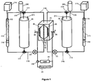
- FIG. 1 shows an arrangement for the RFB combined with the catalytic beds.
- the central part is the electrochemical cell 1, which comprises an ionic membrane 2, and two carbon felt electrodes 3.
- the electrodes may fill both half-cells cavities. Connection to an external power source 4, or an electrical load 5 is shown at sites 6 connecting to the current collectors upon which the felt electrodes 3 are pressed.
- Pumps 7 transfer both electrolytes 8 from their respective storage tank (or reservoir) 9 to the electrochemical cell 1, where they contact the electrodes.
- the electrolytes then flow back to their respective storage tanks, through gas tight tubing 10.
- Inert gas such as nitrogen or argon may be supplied from tanks 20 via inlets 19. To ensure there is no build up of pressure the inert gas can exit the tanks via outlets 21.
- each electrolyte passes through a filter, such as a fritted glass 16, in order to separate the catalytic particles, and then return to their respective storage tanks in the discharged form.
- Valves 17 are used in order to direct the electrolytes flow. This is what we designate the "external circuit".
- the first step is to completely convert both mediators in the electrolytes 8 during the charging process.
- the energy required to achieve this may be sourced from the conventional electric grid at off-peak times, or ideally from renewable energy sources by using solar or wind power.
- the user has two choices: either a classical discharge of the RFB through an electrical load 5 of an energy consuming system (via grid), or transfer of both mediators through the catalytic columns 11, generating H 2 and O 2 .
- the electrochemical mediators are regenerated, and the process of charging may be repeated.
- the electrodes used in a laboratory scale system according to Figure 1 were 5mm-thick carbon felt pieces (SIGRACET ® , SGL Group, Germany), which were first treated at 400 °C, for 4 h, in air. This pre-treatment was to increase the hydrophilicity and electrochemical activity of the electrodes, according to Li, L., Kim, S. et al. (2011). A Stable Vanadium Redox-Flow Battery with High Energy Density for Large-scale Energy Storage. Advanced Energy Materials 1: 394-400 . A high hydrophobicity may be an issue, as air bubbles may be trapped inside the electrodes, and decrease drastically the electrode's efficiency.
- Electrode active surface area is strongly related to the specifications of the battery, and has to be dimensioned according to the intended current and power range.
- 2.5 cm 2 geometric area carbon felt pieces for both electrodes were used.
- the current collectors were a platinum wire at the anode, and a graphite rod at the cathode, or two boron-doped diamond plates as both cathodic and anodic current collectors. Only one monopolar electrochemical cell was tested, however, bipolar electrode stacks may also be used in a large-scale redox flow battery, and, furthermore, alternative current collection systems may be used.
- the electrochemical cell consisted of two chambers of approximately 1.5 cm 3 in polyethylene (PE), both electrodes are only separated by the membrane, and are slightly compressed against the current collector in order to improve the conductivity.
- PE polyethylene
- the design of the electrochemical cell is of importance for the RFB efficiency, in the sense that ohmic losses (due to large distances between the cathode and the anode, for instance) or bypass currents (in the case of bipolar electrodes) may increase the voltage required to charge the battery, and thus lower its overall efficiency.
- ion-selective membranes are used for RFBs, such as ion-exchange filled pore membranes, perfluorinated membranes, and anion-exchange membranes [ Li, X., Zhang, H., Mai, Z., Zhang, H. and Vankelecom I. (2011). Ion exchange membranes for vanadium redox flow battery (VRB) applications. Energy and Environmental Science 4(4), 1147-1160 ].
- three criteria are relevant for the choice of the membrane; ion conductivity, ion selectivity, and chemical stability of the membrane.
- a Nafion N117 (Ion Power Inc., New Castle, DE, US) membrane was used, despite not having optimal ion conductivity and selectivity.
- the membrane was treated in 3% (weight) H 2 O 2 for 1 h, and then in 1M HNO 3 , at 80 °C, for 2 h, and washed at least three times with deionized water.
- the choice of the membrane is a central issue for the efficiency and the functioning of the battery. If the redox mediator cations can pass through the membrane (crosscurrents), the efficiency may, in the long term, strongly decrease, and the electrolyte's lifetime is shortened.
- anionic or cationic membrane is important as it dictates the direction in which the ions travel. This may be crucial for the functioning of the system, since some of these ions are transformed into gases that then leave the system. This will necessitate compensation of the electrolyte periodically.
- various electrolyte compositions may be used on each side. In the present system, only the addition of pure water would be required to replenish the electrolytes.
- the composition of the electrolytes is another key aspect of the present invention: it influences both the RFB electrochemical cell functioning and capacity, and catalytic bed efficiency and poisoning.
- the main parameters are the mediator redox couples and their respective concentrations, the supporting electrolyte and its concentration, the pH, and the volume of both electrolytes. Moreover, deoxygenation of the system has to be considered for the cathodic side especially.
- the choice of mediator redox couples is based on the reactions that will occur in the catalytic beds and on the reversibility of their electrode reactions. For oxygen and hydrogen generation, for instance, we use a cerium-vanadium redox flow battery (Ce-V RFB), and the charging reactions are given by reactions 5a and 6a, and the discharge or chemical regeneration half reactions by reactions 5b and 6b.
- Ce-V RFB cerium-vanadium redox flow battery
- the cerium (IV)/(III) couple is highly sensitive to the nature and concentration of the acid medium, with the redox potential increasing in the order HCl ⁇ H 2 SO 4 ⁇ HNO 3 ⁇ HClO 4 from +1.28 V to +1.70 V in 1 M acid [ Binnemans K, Application of Tetravalent Cerium Compounds in Handbook on the Physics and Chemistry of Rare Earth, Vol 36, 2006 ].
- the reversibility of the cerium couple is also highly dependent on the acid, with sulfate ligands decreasing reversibility considerably, and stabilising the Ce(IV) state.
- the initial salts that are used are VCl 3 and Ce 2 (SO 4 ) 3 or Ce(NO 3 ) 6 (NH 4 ) 2 , and their concentrations range, between 0.5 M and 3 M [Li, X. (2011), supra ], and 0.5 M to 2 M [Leung, P.K. (2011) supra ], respectively.
- concentrations the higher the concentrations, the higher the energy density of the RFB.
- the solubility of the cerium species in high concentration solutions may be problematic [Paulenova et al. (2002), supra ], but an additive, which increases the solubility, may be added to the electrolyte, such as methanesulfonic acid [Leung (2011), supra, US Patent N° 7,270,911 B2 ], for instance.
- the supporting electrolyte is often an acid, and, in most publications, is H 2 SO 4 , with a concentration between 0.1 and 2 M [Li, X. (2011), supra, Rychcik, M. and Skyllas-Kazacos, M. (1988) Characteristics of a new all-vanadium redox flow battery. Journal of Power Sources 22: 59-67 ]. Due to the variation in reduction potential of Ce(IV) in different acids, nitric acid is also an electrolyte in the Ce-V RFB used herein. This acid is used only in the anolyte however, due to the reduction of NO 3 - to NO at 0.96 V vs SHE.
- the supporting electrolyte has the function of decreasing ohmic losses due to migration of the electrochemical species in the electric field generated by both electrodes, and it can also retain the redox species in their desired oxidation state and allow for better solubility of the different mediators.
- Deoxygenation of the system with N 2 or Ar is necessary for the stability of the V(II) ions in the catholyte.
- the inert gas inlets, positioned on the electrolyte tanks allow deoxygenation of both the internal and external circuits.
- the acid concentration strongly affects the hydrogen generation reaction efficiency, but may also affect the efficiency of the chemical oxidation of water.
- the stability of both catalysts upon rather harsh acidic or alkaline conditions must be considered as well.
- an efficient system needs to ensure that no catalyst-poisoning by-products are generated at the electrodes, and inversely that no electrode-poisoning compounds are produced in the catalytic beds.
- the concentration of both redox mediators is another factor to take into account when designing the electrochemical cell; if their concentration is high, the amount of catalyst should be adapted.
- the energy to feed the pumps should be as low as possible to increase the overall efficiency of the system.
- a peristaltic pump was used, working at a flow rate of 10 mL/min through the electrochemical cell 1 and 0.1 mL/min through the catalytic chambers 11.
- the catalytic beds 11 are assembled as follows: In a glass column (e.g. chromatography column) a frit is placed at the bottom with a view to separating the catalyst doped silica or carbon particles and the electrolyte. A hydrogen or oxygen collector is present at the upper aperture of the column, and the gas is then stored in a hydrogen 14 or oxygen 15 storage tank.
- the choice of catalyst dictates the efficiency of the chemical conversion of the mediators, and the gases generated.
- the selectivity and the catalytic activity of the catalyst are two important aspects that have to be examined before possible application in a dual-circuit RFB.
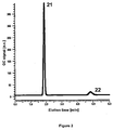
- molybdenum-based catalysts were evaluated and tested in the present system. More specifically, MoS 2 , MoS 3 , and Mo 2 C were studied. Gas chromatography (GC) results have shown that the molybdenum-based catalysts produce significant amounts of H 2 (Peak 21, Figure 2 ), where V(II) is the electron donor, and the sulfuric acid protons the electron acceptors.
- GC Gas chromatography
- This reaction can be monitored quantifiably using UV/vis spectrometry, in which the second, lower energy peak observed in the visible spectrum for V(II) 32 ( Figure 3 ) is quantified over time during the reaction with the Mo catalyst.
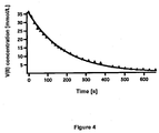
- Kinetic information regarding the rate of reaction can be ascertained with the spectrophotometric data, as V(II) concentration can be plotted against time ( Figure 4 ).
- the plot in Figure 4 gave an apparent rate constant for the catalysed reaction between V(II) and protons to be pseudo first order with respect to the V(II) concentration.
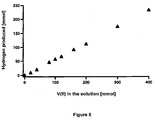
- reaction efficiency with respect to conversion of various concentrations of V(II) to V(III) and H 2 can also be monitored using gas chromatography.
- the results are shown in Figure 5 and indicate a 100% conversion efficiency of V(II) to H 2 gas, within the experimental errors.
- IrO 2 nanoparticles For water oxidation, IrO 2 nanoparticles have been selected due to their well-known catalytic properties for this reaction, and the stability of IrO 2 nanoparticles in acidic pH. Some preliminary tests were somewhat successful in the presence of Ce(IV) as electron acceptor, in 1 M H 2 SO 4 , and in neutral solution (i.e. pure water). In 1 M HNO 3 with cerium (IV) ammonium nitrate (CAN) the catalysed water oxidation is significantly better, visibly evolving copious amount of oxygen and rapidly converting yellow Ce(IV) to colourless Ce(III).
- Figure 6 shows a GC result for oxygen evolved during reaction of Ce(IV) and IrO 2 in a sealed glass vial.
- the overall catalysed chemical reaction of oxygen production is: 4Ce 4+ +2H 2 O ⁇ 4Ce 3+ +O 2 +4H + (7)
- the Ce(IV)/(III) redox couple is thermodynamically capable of oxidising water, an intrinsic kinetic limitation of water oxidation tends to an actual oxidation potential higher than the 1.23 V thermodynamically suggested [ Koper, M. T. M. (2011) Thermodynamic theory of multi-electron transfer reactions: Implications for electrocatalysis Journal of Electroanalytical Chemistry 660: 254-260 ].
- the Ce(IV) reduction potential in 1 M H 2 SO 4 is too low (1.44 V vs.
- the catalysts must be separated from the electrolytes after completion of the chemical reaction. Consequently various strategies may be adopted: Either the nanoparticle catalysts are filtered by a nanofilter, or the catalysts are deposited on a cheap substrate, such as silica particles, and the separation is done by a simple microporous frit, or finally, the catalysts are strongly attached to the walls of thin tubes, through which the electrolytes flow.
- MoS 2 When MoS 2 was used, it was deposited on silica particles by co-synthesis of the catalyst precursor (MoS 3 ) and silica particles, in alkaline conditions (molar ratio MoS 3 : SiO 2 1 : 10) [ Rivera-Munoz, E., Alonso, G., Siadati, M.H., and Chianelli, R.R. (2004). Silica gel-supported, metal-promoted MoS2 catalysts for HDS reactions. Catalysis Letters 94 (3-4):199-204 ].
- the IrO 2 nanoparticles were also deposited on silica to produce a violet powder. This was achieved by first coating the silica particles with a cationic layer of poly(diallyldimethylammonium chloride (PDDA), by stirring the silica in a solution of NaCl and the PDDA for 1 h at room temperature. The silica solution was then centrifuged and washed 3 times with deionisied water, then dried in air at 80 °C for 10 min. The PDDA-silica was then added to a suspension of IrO 2 nanoparticles, synthesised according to Hara et al. [ Hara, M., Lean , J. T., Mallouk, T. E.
- Figure 2 is a GC measurement for the determination of hydrogen following the reaction between the reduced catholyte and Mo 2 C.
- the bottle contained a catalytic amount of Mo 2 C (1 mg) and 2 mL of 20 mM V(II), in 1 M H 2 SO 4 , and the sample was taken after 1 h of reaction (i.e. completion of the reaction).
- the first peak 21 represents the hydrogen produced, whereas the second peak 22 is for the nitrogen gas in the sample.
- Various "blank" experiments (without catalyst and/or electron donor) were conducted in order to verify this result.
- Figure 3 is an overlay of UV/visible spectra for the conversion of V(II) to V(III) over time in the presence of Mo 2 C.
- the reduced catholyte was taken following reduction in the RFB, and comprised 100 mM V(II) in 1 M H 2 SO 4 in the starting condition.
- UV/vis spectra were taken every 30 s until completion (i.e. single peak for V(III) at 600 nm).
- the depletion of the second, lower-energy peak for V(II) 32 was monitored during kinetic analysis, allowing a pseudo first order reaction with respect to V(II) concentration to be determined.
- Figure 5 is a plot for the total generation of hydrogen versus the concentration of V(II). Based on the mole ratios given in equation 6, the chemical reduction of protons to hydrogen occurs with 100 % efficiency (i.e. 100 mmol V(II) gives 50 mmol of hydrogen).
- Figure 6 represents a GC measurement for the determination of oxygen after 1 hour of stirring of the following solution: 2 mL of 100 mM Ce(IV) ammonium nitrate in 1 M HNO 3 , in the presence of 5 mg of the IrO 2 -silica. Peak 61 shows the presence of O 2 , and peak 62 the presence of N 2 . These peaks were compared to "blank" samples, where only peak 62 was observed.
- Figure 8 shows the amount of oxygen produced, and measured in the headspace by GC, as a function of the amount of Ce(IV) in 2 mL of Ce(IV) in 1M HNO 3 .
- the mean conversion is 86 %, indicating some minor side reactions.
- Hydrogen gas was successfully generated from a 2 mL solution containing 1M H 2 SO 4 , 20mM V(II), and 3mg of silica supported MoS 2 or as-bought Mo 2 C powder (SiO 2 : MoS 2 molar ratio is 10:1), under anaerobic conditions, with magnetic stirring for 1h.
- the atmosphere (headspace) above the liquid was sampled by a gas-tight syringe and injected into the GC.
- the result for Mo 2 C ( Figure 2 ) shows the clear presence of H 2 (peak 21) compared to the initial presence of N 2 (peak 22).
- each electrolyte may also contain an acidic supporting electrolyte (e.g . H 2 SO 4 ) at a concentration of 1 M, and an additive for increasing the solubility and stability of the redox species.
- an acidic supporting electrolyte e.g . H 2 SO 4
Landscapes
- Chemical & Material Sciences (AREA)
- Electrochemistry (AREA)
- Chemical Kinetics & Catalysis (AREA)
- Engineering & Computer Science (AREA)
- General Chemical & Material Sciences (AREA)
- Sustainable Development (AREA)
- Sustainable Energy (AREA)
- Life Sciences & Earth Sciences (AREA)
- Manufacturing & Machinery (AREA)
- Materials Engineering (AREA)
- Metallurgy (AREA)
- Organic Chemistry (AREA)
- Inorganic Chemistry (AREA)
- Fuel Cell (AREA)
- Inert Electrodes (AREA)
Applications Claiming Priority (2)
| Application Number | Priority Date | Filing Date | Title |
|---|---|---|---|
| US201261606712P | 2012-03-05 | 2012-03-05 | |
| PCT/EP2013/054238 WO2013131838A1 (en) | 2012-03-05 | 2013-03-04 | Redox flow battery for hydrogen generation |
Publications (2)
| Publication Number | Publication Date |
|---|---|
| EP2823528A1 EP2823528A1 (en) | 2015-01-14 |
| EP2823528B1 true EP2823528B1 (en) | 2016-03-02 |
Family
ID=47757630
Family Applications (1)
| Application Number | Title | Priority Date | Filing Date |
|---|---|---|---|
| EP13707009.0A Active EP2823528B1 (en) | 2012-03-05 | 2013-03-04 | Redox flow battery for hydrogen generation |
Country Status (6)
| Country | Link |
|---|---|
| US (1) | US9543609B2 (enExample) |
| EP (1) | EP2823528B1 (enExample) |
| JP (1) | JP6204382B2 (enExample) |
| CN (1) | CN104272513B (enExample) |
| ES (1) | ES2568759T3 (enExample) |
| WO (1) | WO2013131838A1 (enExample) |
Cited By (15)
| Publication number | Priority date | Publication date | Assignee | Title |
|---|---|---|---|---|
| US11394035B2 (en) | 2017-04-06 | 2022-07-19 | Form Energy, Inc. | Refuelable battery for the electric grid and method of using thereof |
| US11552290B2 (en) | 2018-07-27 | 2023-01-10 | Form Energy, Inc. | Negative electrodes for electrochemical cells |
| US11611115B2 (en) | 2017-12-29 | 2023-03-21 | Form Energy, Inc. | Long life sealed alkaline secondary batteries |
| US11664547B2 (en) | 2016-07-22 | 2023-05-30 | Form Energy, Inc. | Moisture and carbon dioxide management system in electrochemical cells |
| US11949129B2 (en) | 2019-10-04 | 2024-04-02 | Form Energy, Inc. | Refuelable battery for the electric grid and method of using thereof |
| US11973254B2 (en) | 2018-06-29 | 2024-04-30 | Form Energy, Inc. | Aqueous polysulfide-based electrochemical cell |
| US12136723B2 (en) | 2016-07-22 | 2024-11-05 | Form Energy, Inc. | Mist elimination system for electrochemical cells |
| US12237548B2 (en) | 2018-06-29 | 2025-02-25 | Form Energy, Inc. | Stack of electric batteries including series of fluidly connected unit cells |
| US12261281B2 (en) | 2018-06-29 | 2025-03-25 | Form Energy, Inc. | Metal air electrochemical cell architecture |
| US12294086B2 (en) | 2019-07-26 | 2025-05-06 | Form Energy, Inc. | Low cost metal electrodes |
| US12308414B2 (en) | 2019-06-28 | 2025-05-20 | Form Energy, Inc. | Device architectures for metal-air batteries |
| US12381244B2 (en) | 2020-05-06 | 2025-08-05 | Form Energy, Inc. | Decoupled electrode electrochemical energy storage system |
| US12444755B2 (en) | 2016-10-21 | 2025-10-14 | Form Energy, Inc. | Corrugated fuel electrode |
| WO2025221964A1 (en) * | 2024-04-18 | 2025-10-23 | Saudi Arabian Oil Company | Electrochemical device for electrical energy storage and hydrogen production |
| US12476479B2 (en) | 2016-09-15 | 2025-11-18 | Form Energy, Inc. | Hybrid battery system |
Families Citing this family (52)
| Publication number | Priority date | Publication date | Assignee | Title |
|---|---|---|---|---|
| GB201308178D0 (en) * | 2013-05-07 | 2013-06-12 | Acal Energy Ltd | Redox systems |
| KR102364280B1 (ko) | 2013-09-25 | 2022-02-16 | 록히드 마틴 에너지, 엘엘씨 | 플로우 배터리를 위한 전해질 평형화 방법 |
| CN104716373A (zh) * | 2013-12-13 | 2015-06-17 | 中国人民解放军63971部队 | 一种负极为钛电对的液流电池 |
| JP2015232960A (ja) * | 2014-06-10 | 2015-12-24 | 住友電気工業株式会社 | 電池システム |
| JP5850094B2 (ja) * | 2014-06-24 | 2016-02-03 | トヨタ自動車株式会社 | レドックス型燃料電池 |
| JP6408140B2 (ja) | 2014-09-15 | 2018-10-17 | ユナイテッド テクノロジーズ コーポレイションUnited Technologies Corporation | フロー電池電極の再生 |
| DE102014225612A1 (de) * | 2014-12-11 | 2016-06-16 | Fraunhofer-Gesellschaft zur Förderung der angewandten Forschung e.V. | Verfahren zur Regeneration der Elektrolytlösung eines Redox-Flow-Akkumulators |
| US11050078B2 (en) | 2015-01-22 | 2021-06-29 | Battelle Memorial Institute | Systems and methods of decoupled hydrogen generation using energy-bearing redox pairs |
| US11043686B2 (en) | 2015-01-22 | 2021-06-22 | Battelle Memorial Institute | Systems and methods of long-duration energy storage and regeneration of energy-bearing redox pairs |
| US11050076B1 (en) | 2015-01-22 | 2021-06-29 | Battelle Memorial Institute | Flow cell systems, flow cell batteries, and hydrogen production processes |
| EP3284130B1 (en) | 2015-04-14 | 2024-09-11 | Lockheed Martin Energy, LLC | Flow battery balancing cells having a bipolar membrane and methods for use thereof |
| EP3284129B1 (en) | 2015-04-14 | 2020-09-16 | Lockheed Martin Energy, LLC | Flow battery balancing cells having a bipolar membrane for simultaneous modification of a negative electrolyte solution and a positive electrolyte solution |
| BR112017026835A2 (pt) * | 2015-06-16 | 2018-08-14 | Chrome Plated Power SAS | bateria de fluxo redox de alta potência baseada no par redox criii/crvi e sua regeneração mediada |
| EP3316375B1 (en) * | 2015-06-23 | 2020-03-18 | Panasonic Intellectual Property Management Co., Ltd. | Redox flow cell |
| ES2552127B2 (es) * | 2015-07-30 | 2016-10-19 | Universitat D'alacant / Universidad De Alicante | Acumulador electroquímico ácido-base de flujo (AEABF) |
| JP2018536968A (ja) * | 2015-10-09 | 2018-12-13 | ケース ウェスタン リザーブ ユニバーシティCase Western Reserve University | タンク内電解質のリバランス機能を有する密閉された水性フロー電池システム |
| US10347925B2 (en) | 2016-04-29 | 2019-07-09 | Lockheed Martin Energy, Llc | Three-chamber electrochemical balancing cells for simultaneous modification of state of charge and acidity within a flow battery |
| JP6719728B2 (ja) * | 2016-07-26 | 2020-07-08 | 住友電気工業株式会社 | 電解液、電解槽用電解液、及び電解槽システム |
| JP6702170B2 (ja) * | 2016-12-20 | 2020-05-27 | トヨタ自動車株式会社 | 燃料電池システム |
| US10461352B2 (en) * | 2017-03-21 | 2019-10-29 | Lockheed Martin Energy, Llc | Concentration management in flow battery systems using an electrochemical balancing cell |
| JP2019003933A (ja) * | 2017-06-16 | 2019-01-10 | パナソニックIpマネジメント株式会社 | フロー電池 |
| GB201801170D0 (en) | 2018-01-24 | 2018-03-07 | Univ Court Univ Of Glasgow | Use of polyoxometalate mediators |
| GB2570672A (en) * | 2018-02-01 | 2019-08-07 | Ac Chemical Systems Ltd | Reversible cell |
| US12286711B2 (en) * | 2018-02-27 | 2025-04-29 | California Institute Of Technology | Use of intermediates in solar fuels generation |
| US11177497B2 (en) * | 2018-03-12 | 2021-11-16 | Washington University | Redox flow battery |
| IL258252A (en) * | 2018-03-20 | 2018-06-28 | Technion Res & Development Found Ltd | System and method for generation of gases |
| FR3079530B1 (fr) | 2018-04-03 | 2024-04-26 | Ergosup | Procede electrochimique de production d'hydrogene gazeux sous pression par electrolyse puis par conversion electrochimique |
| CN108808030B (zh) * | 2018-07-03 | 2023-08-08 | 重庆大学 | 基于b-z振荡反应的脉冲电池设计 |
| US11056698B2 (en) | 2018-08-02 | 2021-07-06 | Raytheon Technologies Corporation | Redox flow battery with electrolyte balancing and compatibility enabling features |
| CN110835764B (zh) * | 2018-08-17 | 2021-05-25 | 中国科学院大连化学物理研究所 | 一种耦联太阳光催化分解水与液流电池产氢发电的方法 |
| CN109461955A (zh) * | 2018-11-02 | 2019-03-12 | 浙江晨阳新材料有限公司 | 一种燃料电池系统 |
| WO2020106549A1 (en) * | 2018-11-20 | 2020-05-28 | Ess Tech, Inc. | Electrolyte health management for redox flow battery |
| DE102019104401A1 (de) * | 2019-01-22 | 2020-07-23 | Deutsches Zentrum für Luft- und Raumfahrt e.V. | Elektrolyseur und Verfahren zum Aufspalten von Wasser |
| US11203812B2 (en) * | 2019-02-22 | 2021-12-21 | New York University | Methods and electrochemical cells for redox mediated hydrogen production |
| US11313044B2 (en) * | 2019-08-20 | 2022-04-26 | Deutsches Zentrum fuer Loft- und Raumfahrt e.V. | Electrolyzer and method for splitting water |
| EP4046220A4 (en) * | 2019-11-08 | 2024-12-18 | ESS Tech, Inc. | Multi-stage rebalancing reactor for redox flow battery system |
| CN111962091A (zh) * | 2020-08-20 | 2020-11-20 | 上海电气集团股份有限公司 | 一种电解水方法及装置 |
| US20230407490A1 (en) * | 2020-11-04 | 2023-12-21 | National University Of Singapore | A water electrolyzer system |
| US20230411662A1 (en) * | 2020-11-30 | 2023-12-21 | Cmblu Energy Ag | Electrolyte Regeneration for Organic Redox Flow Batteries Based on Water-Soluble Phenzaine-Based Compounds |
| KR20220075650A (ko) * | 2020-11-30 | 2022-06-08 | 롯데케미칼 주식회사 | 바나듐 레독스 흐름 전지용 전해액의 제조방법 |
| US11271226B1 (en) | 2020-12-11 | 2022-03-08 | Raytheon Technologies Corporation | Redox flow battery with improved efficiency |
| AU2022228486A1 (en) * | 2021-03-01 | 2023-09-28 | Verdagy, Inc. | Systems and methods to make hydrogen gas |
| CN113416972A (zh) * | 2021-05-31 | 2021-09-21 | 复旦大学 | 基于全钒液流氧化还原媒介分步电解水制氢的装置和方法 |
| FR3127234A1 (fr) * | 2021-09-21 | 2023-03-24 | Totalenergies Se | Procédé de génération continue d’hydrogène par électrolyse de l’eau via une approche découplée |
| EP4409056A2 (en) | 2021-09-28 | 2024-08-07 | Verdagy, Inc. | Systems and methods to make hydrogen gas with a steady-state ph differential |
| EP4523270A4 (en) | 2022-05-09 | 2026-04-22 | Lockheed Martin Energy Llc | CIRCULATING BATTERY INCLUDING A DYNAMIC FLUID NETWORK |
| WO2024106161A1 (ja) | 2022-11-18 | 2024-05-23 | Eneos株式会社 | 電解システムおよび電解方法 |
| CN116288416B (zh) * | 2022-11-28 | 2025-09-19 | 上海交通大学 | 一种基于液流电池再生循环so2资源化回收系统及方法 |
| US20240191360A1 (en) * | 2022-12-09 | 2024-06-13 | Tokyo Ohka Kogyo Co., Ltd. | Chemical solution for removing precious metal, method for manufacturing chemical solution, method for treating substrate, method for manufacturing semiconductor device |
| US20240218526A1 (en) * | 2022-12-15 | 2024-07-04 | California Institute Of Technology | Systems for Direct Generation of High-Pressure Hydrogen Gas and Methods Thereof |
| CN116377489B (zh) * | 2023-02-16 | 2026-01-06 | 中国科学院福建物质结构研究所 | 一种通过水系可充电金属-催化剂电池高效分离制氢的方法 |
| CN121307115B (zh) * | 2025-12-10 | 2026-03-06 | 大连融科储能集团股份有限公司 | 液流电池容量恢复系统及方法 |
Family Cites Families (21)
| Publication number | Priority date | Publication date | Assignee | Title |
|---|---|---|---|---|
| US4159366A (en) | 1978-06-09 | 1979-06-26 | The United States Of America As Represented By The Administrator Of The National Aeronautics And Space Administration | Electrochemical cell for rebalancing redox flow system |
| US4469760A (en) | 1981-09-08 | 1984-09-04 | Electric Power Research, Institute | Redox battery including a bromine positive electrode and a chromium ion negative electrode, and method |
| US4576878A (en) * | 1985-06-25 | 1986-03-18 | The United States Of America As Represented By The Administrator Of The National Aeronautics And Space Administration | Method and apparatus for rebalancing a redox flow cell system |
| US4786567A (en) | 1986-02-11 | 1988-11-22 | Unisearch Limited | All-vanadium redox battery |
| JPH0815093B2 (ja) * | 1986-05-24 | 1996-02-14 | 住友電気工業株式会社 | 電解液循環型2次電池 |
| ES2029707T3 (es) | 1987-10-23 | 1992-09-01 | Siemens Aktiengesellschaft | Bateria redox |
| JP2649700B2 (ja) | 1988-06-03 | 1997-09-03 | 関西電力株式会社 | レドックスフロー電池の電解液再生装置 |
| DE3843312A1 (de) * | 1988-12-22 | 1990-06-28 | Siemens Ag | Ausgleichszelle fuer einen cr/fe-redoxionenspeicher |
| JPH06260204A (ja) * | 1993-03-01 | 1994-09-16 | Sumitomo Electric Ind Ltd | 電解液再調整装置付電解液流通型電池 |
| SE9304203L (sv) * | 1993-12-20 | 1994-11-21 | Ragnar Larsson | Förfarande för produktion av elektrisk energi i en biobränsledriven bränslecell |
| JPH09172195A (ja) | 1995-12-20 | 1997-06-30 | Ebara Corp | 蓄電池内蔵型太陽電池 |
| JP3098961B2 (ja) * | 1996-07-24 | 2000-10-16 | 住友電気工業株式会社 | レドックスフロー電池およびその運転方法 |
| JP2001093560A (ja) * | 1999-09-27 | 2001-04-06 | Kashimakita Kyodo Hatsuden Kk | レドックスフロー電池 |
| US20060063065A1 (en) * | 2001-08-10 | 2006-03-23 | Clarke Robert L | Battery with bifunctional electrolyte |
| US7270911B2 (en) | 2001-08-10 | 2007-09-18 | Plurion Limited | Load leveling battery and methods therefor |
| US7740977B2 (en) | 2007-03-26 | 2010-06-22 | Jd Holding Inc. | Vanadium redox battery incorporating multiple electrolyte reservoirs |
| US7820321B2 (en) | 2008-07-07 | 2010-10-26 | Enervault Corporation | Redox flow battery system for distributed energy storage |
| CN102460811B (zh) * | 2009-05-28 | 2015-11-25 | 艾默吉电力系统股份有限公司 | 氧化还原流通单元电池再平衡 |
| US20130056076A1 (en) * | 2010-03-02 | 2013-03-07 | Acal Energy Ltd | Bubbles generation device and method |
| CN101901937B (zh) * | 2010-08-17 | 2012-07-04 | 天津久聚能源科技发展有限公司 | 银离子作为正极催化剂的铈离子电解液及其制备方法 |
| GB201200250D0 (en) * | 2012-01-09 | 2012-02-22 | Imp Innovations Ltd | Regenerative fuel cells |
-
2013
- 2013-03-04 WO PCT/EP2013/054238 patent/WO2013131838A1/en not_active Ceased
- 2013-03-04 CN CN201380022949.5A patent/CN104272513B/zh active Active
- 2013-03-04 EP EP13707009.0A patent/EP2823528B1/en active Active
- 2013-03-04 JP JP2014560318A patent/JP6204382B2/ja active Active
- 2013-03-04 US US14/382,732 patent/US9543609B2/en active Active
- 2013-03-04 ES ES13707009.0T patent/ES2568759T3/es active Active
Cited By (15)
| Publication number | Priority date | Publication date | Assignee | Title |
|---|---|---|---|---|
| US12136723B2 (en) | 2016-07-22 | 2024-11-05 | Form Energy, Inc. | Mist elimination system for electrochemical cells |
| US11664547B2 (en) | 2016-07-22 | 2023-05-30 | Form Energy, Inc. | Moisture and carbon dioxide management system in electrochemical cells |
| US12476479B2 (en) | 2016-09-15 | 2025-11-18 | Form Energy, Inc. | Hybrid battery system |
| US12444755B2 (en) | 2016-10-21 | 2025-10-14 | Form Energy, Inc. | Corrugated fuel electrode |
| US11394035B2 (en) | 2017-04-06 | 2022-07-19 | Form Energy, Inc. | Refuelable battery for the electric grid and method of using thereof |
| US11611115B2 (en) | 2017-12-29 | 2023-03-21 | Form Energy, Inc. | Long life sealed alkaline secondary batteries |
| US12237548B2 (en) | 2018-06-29 | 2025-02-25 | Form Energy, Inc. | Stack of electric batteries including series of fluidly connected unit cells |
| US11973254B2 (en) | 2018-06-29 | 2024-04-30 | Form Energy, Inc. | Aqueous polysulfide-based electrochemical cell |
| US12261281B2 (en) | 2018-06-29 | 2025-03-25 | Form Energy, Inc. | Metal air electrochemical cell architecture |
| US11552290B2 (en) | 2018-07-27 | 2023-01-10 | Form Energy, Inc. | Negative electrodes for electrochemical cells |
| US12308414B2 (en) | 2019-06-28 | 2025-05-20 | Form Energy, Inc. | Device architectures for metal-air batteries |
| US12294086B2 (en) | 2019-07-26 | 2025-05-06 | Form Energy, Inc. | Low cost metal electrodes |
| US11949129B2 (en) | 2019-10-04 | 2024-04-02 | Form Energy, Inc. | Refuelable battery for the electric grid and method of using thereof |
| US12381244B2 (en) | 2020-05-06 | 2025-08-05 | Form Energy, Inc. | Decoupled electrode electrochemical energy storage system |
| WO2025221964A1 (en) * | 2024-04-18 | 2025-10-23 | Saudi Arabian Oil Company | Electrochemical device for electrical energy storage and hydrogen production |
Also Published As
| Publication number | Publication date |
|---|---|
| CN104272513A (zh) | 2015-01-07 |
| US9543609B2 (en) | 2017-01-10 |
| CN104272513B (zh) | 2017-07-18 |
| ES2568759T3 (es) | 2016-05-04 |
| EP2823528A1 (en) | 2015-01-14 |
| JP6204382B2 (ja) | 2017-09-27 |
| WO2013131838A1 (en) | 2013-09-12 |
| JP2015509650A (ja) | 2015-03-30 |
| US20150017494A1 (en) | 2015-01-15 |
Similar Documents
| Publication | Publication Date | Title |
|---|---|---|
| EP2823528B1 (en) | Redox flow battery for hydrogen generation | |
| Zhang et al. | Redox-mediated water splitting for decoupled H2 production | |
| Ifkovits et al. | Decoupled electrochemical water-splitting systems: a review and perspective | |
| McHugh et al. | Decoupled electrochemical water splitting: from fundamentals to applications | |
| Fan et al. | Efficient hydrogen peroxide synthesis by metal-free polyterthiophene via photoelectrocatalytic dioxygen reduction | |
| Amstutz et al. | Renewable hydrogen generation from a dual-circuit redox flow battery | |
| JP7231409B2 (ja) | 再生燃料電池 | |
| JP6189327B2 (ja) | 再生燃料電池 | |
| US11050076B1 (en) | Flow cell systems, flow cell batteries, and hydrogen production processes | |
| Ju et al. | Role of iron species as mediator in a PEM based carbon-water co-electrolysis for cost-effective hydrogen production | |
| Ji et al. | Spatially decoupled hydrogen evolution in alkaline conditions with a redox targeting-based flow battery | |
| Cao et al. | Vanadium-mediated high areal capacity zinc–manganese redox flow battery | |
| Xie et al. | Electrochemical systems for renewable energy conversion and storage: Focus on flow batteries and regenerative fuel cells | |
| Wang et al. | Sustainable coproduction of two disinfectants via hydroxide-balanced modular electrochemical synthesis using a redox reservoir | |
| Xia et al. | Entropy-directed metal–organic frameworks drive solar-electrolytic water splitting | |
| Zhang et al. | Redox-mediated electrocatalytic and photocatalytic hydrogen production | |
| Mathur et al. | Advanced device architecture strategies for decoupled water splitting: a review | |
| JP2004256378A (ja) | 水素及び酸素の製造方法及びその装置 | |
| Han et al. | A low temperature aqueous formate fuel cell using cobalt hexacyanoferrate as a non-noble metal oxidation catalyst | |
| Kamiya et al. | Gaseous CO 2 electrolysis: latest advances in electrode and electrolyzer technologies toward abating CO 2 emissions | |
| Reynard et al. | Redox‐mediated Processes | |
| Ye et al. | Bioanode‐driven CO2 electroreduction in a redox‐medium‐assisted system with high energy efficiency | |
| KR102610400B1 (ko) | 신재생 에너지 및 연료 전지를 이용하는 복합 발전 시스템 및 이에 사용되는 수소 생산 시스템 | |
| Lahkar | Development of electrocatalysts for Hydrogen Evolution Reaction in acidic medium | |
| US20230010771A1 (en) | Devices and methods for electrocatalytic hydrogen production |
Legal Events
| Date | Code | Title | Description |
|---|---|---|---|
| PUAI | Public reference made under article 153(3) epc to a published international application that has entered the european phase |
Free format text: ORIGINAL CODE: 0009012 |
|
| 17P | Request for examination filed |
Effective date: 20140901 |
|
| AK | Designated contracting states |
Kind code of ref document: A1 Designated state(s): AL AT BE BG CH CY CZ DE DK EE ES FI FR GB GR HR HU IE IS IT LI LT LU LV MC MK MT NL NO PL PT RO RS SE SI SK SM TR |
|
| AX | Request for extension of the european patent |
Extension state: BA ME |
|
| DAX | Request for extension of the european patent (deleted) | ||
| REG | Reference to a national code |
Ref country code: DE Ref legal event code: R079 Ref document number: 602013005242 Country of ref document: DE Free format text: PREVIOUS MAIN CLASS: H01M0008060000 Ipc: H01M0008200000 |
|
| GRAP | Despatch of communication of intention to grant a patent |
Free format text: ORIGINAL CODE: EPIDOSNIGR1 |
|
| RIC1 | Information provided on ipc code assigned before grant |
Ipc: H01M 8/08 20060101ALI20150819BHEP Ipc: H01M 8/04 20060101ALI20150819BHEP Ipc: H01M 8/06 20060101ALI20150819BHEP Ipc: H01M 8/22 20060101ALI20150819BHEP Ipc: H01M 8/20 20060101AFI20150819BHEP Ipc: H01M 8/18 20060101ALI20150819BHEP |
|
| INTG | Intention to grant announced |
Effective date: 20150914 |
|
| GRAS | Grant fee paid |
Free format text: ORIGINAL CODE: EPIDOSNIGR3 |
|
| GRAA | (expected) grant |
Free format text: ORIGINAL CODE: 0009210 |
|
| AK | Designated contracting states |
Kind code of ref document: B1 Designated state(s): AL AT BE BG CH CY CZ DE DK EE ES FI FR GB GR HR HU IE IS IT LI LT LU LV MC MK MT NL NO PL PT RO RS SE SI SK SM TR |
|
| REG | Reference to a national code |
Ref country code: GB Ref legal event code: FG4D |
|
| REG | Reference to a national code |
Ref country code: FR Ref legal event code: PLFP Year of fee payment: 4 |
|
| REG | Reference to a national code |
Ref country code: AT Ref legal event code: REF Ref document number: 778568 Country of ref document: AT Kind code of ref document: T Effective date: 20160315 Ref country code: CH Ref legal event code: EP Ref country code: CH Ref legal event code: NV Representative=s name: STUMP UND PARTNER PATENTANWAELTE AG, CH |
|
| REG | Reference to a national code |
Ref country code: IE Ref legal event code: FG4D |
|
| REG | Reference to a national code |
Ref country code: DE Ref legal event code: R096 Ref document number: 602013005242 Country of ref document: DE |
|
| REG | Reference to a national code |
Ref country code: NL Ref legal event code: FP |
|
| PGFP | Annual fee paid to national office [announced via postgrant information from national office to epo] |
Ref country code: CH Payment date: 20160315 Year of fee payment: 4 |
|
| REG | Reference to a national code |
Ref country code: ES Ref legal event code: FG2A Ref document number: 2568759 Country of ref document: ES Kind code of ref document: T3 Effective date: 20160504 |
|
| REG | Reference to a national code |
Ref country code: LT Ref legal event code: MG4D |
|
| REG | Reference to a national code |
Ref country code: AT Ref legal event code: MK05 Ref document number: 778568 Country of ref document: AT Kind code of ref document: T Effective date: 20160302 |
|
| PG25 | Lapsed in a contracting state [announced via postgrant information from national office to epo] |
Ref country code: NO Free format text: LAPSE BECAUSE OF FAILURE TO SUBMIT A TRANSLATION OF THE DESCRIPTION OR TO PAY THE FEE WITHIN THE PRESCRIBED TIME-LIMIT Effective date: 20160602 Ref country code: GR Free format text: LAPSE BECAUSE OF FAILURE TO SUBMIT A TRANSLATION OF THE DESCRIPTION OR TO PAY THE FEE WITHIN THE PRESCRIBED TIME-LIMIT Effective date: 20160603 Ref country code: FI Free format text: LAPSE BECAUSE OF FAILURE TO SUBMIT A TRANSLATION OF THE DESCRIPTION OR TO PAY THE FEE WITHIN THE PRESCRIBED TIME-LIMIT Effective date: 20160302 Ref country code: HR Free format text: LAPSE BECAUSE OF FAILURE TO SUBMIT A TRANSLATION OF THE DESCRIPTION OR TO PAY THE FEE WITHIN THE PRESCRIBED TIME-LIMIT Effective date: 20160302 |
|
| PG25 | Lapsed in a contracting state [announced via postgrant information from national office to epo] |
Ref country code: LV Free format text: LAPSE BECAUSE OF FAILURE TO SUBMIT A TRANSLATION OF THE DESCRIPTION OR TO PAY THE FEE WITHIN THE PRESCRIBED TIME-LIMIT Effective date: 20160302 Ref country code: SE Free format text: LAPSE BECAUSE OF FAILURE TO SUBMIT A TRANSLATION OF THE DESCRIPTION OR TO PAY THE FEE WITHIN THE PRESCRIBED TIME-LIMIT Effective date: 20160302 Ref country code: AT Free format text: LAPSE BECAUSE OF FAILURE TO SUBMIT A TRANSLATION OF THE DESCRIPTION OR TO PAY THE FEE WITHIN THE PRESCRIBED TIME-LIMIT Effective date: 20160302 Ref country code: LT Free format text: LAPSE BECAUSE OF FAILURE TO SUBMIT A TRANSLATION OF THE DESCRIPTION OR TO PAY THE FEE WITHIN THE PRESCRIBED TIME-LIMIT Effective date: 20160302 Ref country code: BE Free format text: LAPSE BECAUSE OF NON-PAYMENT OF DUE FEES Effective date: 20160331 Ref country code: RS Free format text: LAPSE BECAUSE OF FAILURE TO SUBMIT A TRANSLATION OF THE DESCRIPTION OR TO PAY THE FEE WITHIN THE PRESCRIBED TIME-LIMIT Effective date: 20160302 Ref country code: PL Free format text: LAPSE BECAUSE OF FAILURE TO SUBMIT A TRANSLATION OF THE DESCRIPTION OR TO PAY THE FEE WITHIN THE PRESCRIBED TIME-LIMIT Effective date: 20160302 |
|
| PG25 | Lapsed in a contracting state [announced via postgrant information from national office to epo] |
Ref country code: EE Free format text: LAPSE BECAUSE OF FAILURE TO SUBMIT A TRANSLATION OF THE DESCRIPTION OR TO PAY THE FEE WITHIN THE PRESCRIBED TIME-LIMIT Effective date: 20160302 Ref country code: IS Free format text: LAPSE BECAUSE OF FAILURE TO SUBMIT A TRANSLATION OF THE DESCRIPTION OR TO PAY THE FEE WITHIN THE PRESCRIBED TIME-LIMIT Effective date: 20160702 |
|
| PG25 | Lapsed in a contracting state [announced via postgrant information from national office to epo] |
Ref country code: RO Free format text: LAPSE BECAUSE OF FAILURE TO SUBMIT A TRANSLATION OF THE DESCRIPTION OR TO PAY THE FEE WITHIN THE PRESCRIBED TIME-LIMIT Effective date: 20160302 Ref country code: SK Free format text: LAPSE BECAUSE OF FAILURE TO SUBMIT A TRANSLATION OF THE DESCRIPTION OR TO PAY THE FEE WITHIN THE PRESCRIBED TIME-LIMIT Effective date: 20160302 Ref country code: SM Free format text: LAPSE BECAUSE OF FAILURE TO SUBMIT A TRANSLATION OF THE DESCRIPTION OR TO PAY THE FEE WITHIN THE PRESCRIBED TIME-LIMIT Effective date: 20160302 Ref country code: PT Free format text: LAPSE BECAUSE OF FAILURE TO SUBMIT A TRANSLATION OF THE DESCRIPTION OR TO PAY THE FEE WITHIN THE PRESCRIBED TIME-LIMIT Effective date: 20160704 Ref country code: CZ Free format text: LAPSE BECAUSE OF FAILURE TO SUBMIT A TRANSLATION OF THE DESCRIPTION OR TO PAY THE FEE WITHIN THE PRESCRIBED TIME-LIMIT Effective date: 20160302 |
|
| REG | Reference to a national code |
Ref country code: DE Ref legal event code: R097 Ref document number: 602013005242 Country of ref document: DE |
|
| PG25 | Lapsed in a contracting state [announced via postgrant information from national office to epo] |
Ref country code: BE Free format text: LAPSE BECAUSE OF FAILURE TO SUBMIT A TRANSLATION OF THE DESCRIPTION OR TO PAY THE FEE WITHIN THE PRESCRIBED TIME-LIMIT Effective date: 20160302 |
|
| PLBE | No opposition filed within time limit |
Free format text: ORIGINAL CODE: 0009261 |
|
| STAA | Information on the status of an ep patent application or granted ep patent |
Free format text: STATUS: NO OPPOSITION FILED WITHIN TIME LIMIT |
|
| PG25 | Lapsed in a contracting state [announced via postgrant information from national office to epo] |
Ref country code: DK Free format text: LAPSE BECAUSE OF FAILURE TO SUBMIT A TRANSLATION OF THE DESCRIPTION OR TO PAY THE FEE WITHIN THE PRESCRIBED TIME-LIMIT Effective date: 20160302 |
|
| 26N | No opposition filed |
Effective date: 20161205 |
|
| PG25 | Lapsed in a contracting state [announced via postgrant information from national office to epo] |
Ref country code: SI Free format text: LAPSE BECAUSE OF FAILURE TO SUBMIT A TRANSLATION OF THE DESCRIPTION OR TO PAY THE FEE WITHIN THE PRESCRIBED TIME-LIMIT Effective date: 20160302 Ref country code: BG Free format text: LAPSE BECAUSE OF FAILURE TO SUBMIT A TRANSLATION OF THE DESCRIPTION OR TO PAY THE FEE WITHIN THE PRESCRIBED TIME-LIMIT Effective date: 20160602 |
|
| REG | Reference to a national code |
Ref country code: FR Ref legal event code: PLFP Year of fee payment: 5 |
|
| PG25 | Lapsed in a contracting state [announced via postgrant information from national office to epo] |
Ref country code: MT Free format text: LAPSE BECAUSE OF FAILURE TO SUBMIT A TRANSLATION OF THE DESCRIPTION OR TO PAY THE FEE WITHIN THE PRESCRIBED TIME-LIMIT Effective date: 20160302 |
|
| REG | Reference to a national code |
Ref country code: CH Ref legal event code: PL |
|
| PG25 | Lapsed in a contracting state [announced via postgrant information from national office to epo] |
Ref country code: LI Free format text: LAPSE BECAUSE OF NON-PAYMENT OF DUE FEES Effective date: 20170331 Ref country code: CH Free format text: LAPSE BECAUSE OF NON-PAYMENT OF DUE FEES Effective date: 20170331 |
|
| REG | Reference to a national code |
Ref country code: FR Ref legal event code: PLFP Year of fee payment: 6 |
|
| PG25 | Lapsed in a contracting state [announced via postgrant information from national office to epo] |
Ref country code: HU Free format text: LAPSE BECAUSE OF FAILURE TO SUBMIT A TRANSLATION OF THE DESCRIPTION OR TO PAY THE FEE WITHIN THE PRESCRIBED TIME-LIMIT; INVALID AB INITIO Effective date: 20130304 |
|
| PG25 | Lapsed in a contracting state [announced via postgrant information from national office to epo] |
Ref country code: MT Free format text: LAPSE BECAUSE OF FAILURE TO SUBMIT A TRANSLATION OF THE DESCRIPTION OR TO PAY THE FEE WITHIN THE PRESCRIBED TIME-LIMIT Effective date: 20160331 Ref country code: MC Free format text: LAPSE BECAUSE OF FAILURE TO SUBMIT A TRANSLATION OF THE DESCRIPTION OR TO PAY THE FEE WITHIN THE PRESCRIBED TIME-LIMIT Effective date: 20160302 Ref country code: MK Free format text: LAPSE BECAUSE OF FAILURE TO SUBMIT A TRANSLATION OF THE DESCRIPTION OR TO PAY THE FEE WITHIN THE PRESCRIBED TIME-LIMIT Effective date: 20160302 Ref country code: LU Free format text: LAPSE BECAUSE OF NON-PAYMENT OF DUE FEES Effective date: 20160304 Ref country code: CY Free format text: LAPSE BECAUSE OF FAILURE TO SUBMIT A TRANSLATION OF THE DESCRIPTION OR TO PAY THE FEE WITHIN THE PRESCRIBED TIME-LIMIT Effective date: 20160302 |
|
| PG25 | Lapsed in a contracting state [announced via postgrant information from national office to epo] |
Ref country code: TR Free format text: LAPSE BECAUSE OF FAILURE TO SUBMIT A TRANSLATION OF THE DESCRIPTION OR TO PAY THE FEE WITHIN THE PRESCRIBED TIME-LIMIT Effective date: 20160302 Ref country code: AL Free format text: LAPSE BECAUSE OF FAILURE TO SUBMIT A TRANSLATION OF THE DESCRIPTION OR TO PAY THE FEE WITHIN THE PRESCRIBED TIME-LIMIT Effective date: 20160302 |
|
| PGFP | Annual fee paid to national office [announced via postgrant information from national office to epo] |
Ref country code: ES Payment date: 20250417 Year of fee payment: 13 |
|
| PGFP | Annual fee paid to national office [announced via postgrant information from national office to epo] |
Ref country code: GB Payment date: 20260324 Year of fee payment: 14 |
|
| PGFP | Annual fee paid to national office [announced via postgrant information from national office to epo] |
Ref country code: IE Payment date: 20260126 Year of fee payment: 14 Ref country code: DE Payment date: 20260319 Year of fee payment: 14 |
|
| PGFP | Annual fee paid to national office [announced via postgrant information from national office to epo] |
Ref country code: IT Payment date: 20260324 Year of fee payment: 14 |
|
| PGFP | Annual fee paid to national office [announced via postgrant information from national office to epo] |
Ref country code: NL Payment date: 20260319 Year of fee payment: 14 |
|
| PGFP | Annual fee paid to national office [announced via postgrant information from national office to epo] |
Ref country code: FR Payment date: 20260320 Year of fee payment: 14 |