EP2821231A2 - Tintenstrahlaufzeichnungsvorrichtung mit Rückgewinnungsvorrichtung eines Aufzeichnungskopfes - Google Patents
Tintenstrahlaufzeichnungsvorrichtung mit Rückgewinnungsvorrichtung eines Aufzeichnungskopfes Download PDFInfo
- Publication number
- EP2821231A2 EP2821231A2 EP14173287.5A EP14173287A EP2821231A2 EP 2821231 A2 EP2821231 A2 EP 2821231A2 EP 14173287 A EP14173287 A EP 14173287A EP 2821231 A2 EP2821231 A2 EP 2821231A2
- Authority
- EP
- European Patent Office
- Prior art keywords
- ink
- ink discharge
- face
- discharge face
- wipers
- Prior art date
- Legal status (The legal status is an assumption and is not a legal conclusion. Google has not performed a legal analysis and makes no representation as to the accuracy of the status listed.)
- Granted
Links
Images














Classifications
-
- B—PERFORMING OPERATIONS; TRANSPORTING
- B41—PRINTING; LINING MACHINES; TYPEWRITERS; STAMPS
- B41J—TYPEWRITERS; SELECTIVE PRINTING MECHANISMS, i.e. MECHANISMS PRINTING OTHERWISE THAN FROM A FORME; CORRECTION OF TYPOGRAPHICAL ERRORS
- B41J2/00—Typewriters or selective printing mechanisms characterised by the printing or marking process for which they are designed
- B41J2/005—Typewriters or selective printing mechanisms characterised by the printing or marking process for which they are designed characterised by bringing liquid or particles selectively into contact with a printing material
- B41J2/01—Ink jet
- B41J2/135—Nozzles
- B41J2/165—Prevention or detection of nozzle clogging, e.g. cleaning, capping or moistening for nozzles
- B41J2/16517—Cleaning of print head nozzles
- B41J2/16535—Cleaning of print head nozzles using wiping constructions
- B41J2/16538—Cleaning of print head nozzles using wiping constructions with brushes or wiper blades perpendicular to the nozzle plate
-
- B—PERFORMING OPERATIONS; TRANSPORTING
- B41—PRINTING; LINING MACHINES; TYPEWRITERS; STAMPS
- B41J—TYPEWRITERS; SELECTIVE PRINTING MECHANISMS, i.e. MECHANISMS PRINTING OTHERWISE THAN FROM A FORME; CORRECTION OF TYPOGRAPHICAL ERRORS
- B41J2/00—Typewriters or selective printing mechanisms characterised by the printing or marking process for which they are designed
- B41J2/005—Typewriters or selective printing mechanisms characterised by the printing or marking process for which they are designed characterised by bringing liquid or particles selectively into contact with a printing material
- B41J2/01—Ink jet
- B41J2/135—Nozzles
- B41J2/165—Prevention or detection of nozzle clogging, e.g. cleaning, capping or moistening for nozzles
- B41J2/16517—Cleaning of print head nozzles
- B41J2/16535—Cleaning of print head nozzles using wiping constructions
-
- B—PERFORMING OPERATIONS; TRANSPORTING
- B41—PRINTING; LINING MACHINES; TYPEWRITERS; STAMPS
- B41J—TYPEWRITERS; SELECTIVE PRINTING MECHANISMS, i.e. MECHANISMS PRINTING OTHERWISE THAN FROM A FORME; CORRECTION OF TYPOGRAPHICAL ERRORS
- B41J2/00—Typewriters or selective printing mechanisms characterised by the printing or marking process for which they are designed
- B41J2/005—Typewriters or selective printing mechanisms characterised by the printing or marking process for which they are designed characterised by bringing liquid or particles selectively into contact with a printing material
- B41J2/01—Ink jet
- B41J2/135—Nozzles
- B41J2/165—Prevention or detection of nozzle clogging, e.g. cleaning, capping or moistening for nozzles
- B41J2/16517—Cleaning of print head nozzles
- B41J2/16535—Cleaning of print head nozzles using wiping constructions
- B41J2/16544—Constructions for the positioning of wipers
-
- B—PERFORMING OPERATIONS; TRANSPORTING
- B41—PRINTING; LINING MACHINES; TYPEWRITERS; STAMPS
- B41J—TYPEWRITERS; SELECTIVE PRINTING MECHANISMS, i.e. MECHANISMS PRINTING OTHERWISE THAN FROM A FORME; CORRECTION OF TYPOGRAPHICAL ERRORS
- B41J2/00—Typewriters or selective printing mechanisms characterised by the printing or marking process for which they are designed
- B41J2/005—Typewriters or selective printing mechanisms characterised by the printing or marking process for which they are designed characterised by bringing liquid or particles selectively into contact with a printing material
- B41J2/01—Ink jet
- B41J2/135—Nozzles
- B41J2/165—Prevention or detection of nozzle clogging, e.g. cleaning, capping or moistening for nozzles
- B41J2/16585—Prevention or detection of nozzle clogging, e.g. cleaning, capping or moistening for nozzles for paper-width or non-reciprocating print heads
-
- B—PERFORMING OPERATIONS; TRANSPORTING
- B41—PRINTING; LINING MACHINES; TYPEWRITERS; STAMPS
- B41J—TYPEWRITERS; SELECTIVE PRINTING MECHANISMS, i.e. MECHANISMS PRINTING OTHERWISE THAN FROM A FORME; CORRECTION OF TYPOGRAPHICAL ERRORS
- B41J2/00—Typewriters or selective printing mechanisms characterised by the printing or marking process for which they are designed
- B41J2/005—Typewriters or selective printing mechanisms characterised by the printing or marking process for which they are designed characterised by bringing liquid or particles selectively into contact with a printing material
- B41J2/01—Ink jet
- B41J2/135—Nozzles
- B41J2/165—Prevention or detection of nozzle clogging, e.g. cleaning, capping or moistening for nozzles
- B41J2/16585—Prevention or detection of nozzle clogging, e.g. cleaning, capping or moistening for nozzles for paper-width or non-reciprocating print heads
- B41J2002/16591—Prevention or detection of nozzle clogging, e.g. cleaning, capping or moistening for nozzles for paper-width or non-reciprocating print heads for line print heads above an endless belt
Definitions
- a recording apparatus such as a facsimile, a copier, and a printer is constituted so as to record an image to a recording medium such as a paper and an OHP sheet.
- the recording apparatus can be classified into an ink jet type, a wire dot type, a thermal type, or a similar type depending on a recording method.
- An ink jet recording method is classified into a serial type and a line head type.
- the serial type performs recording by scanning a recording head on a recording medium.
- the line head type performs recording with the recording head secured to an apparatus main body.
- An ink-jet recording apparatus of line head type includes line head type inkjet heads (recording heads) for respective colors.
- the inkjet heads each have discharge nozzles.
- the discharge nozzles align at predetermined intervals across a whole print region width perpendicular to a conveyance direction of a recording medium.
- the ink-jet recording apparatus of line head type discharges ink from the discharge nozzles corresponding to a printing position in synchronization with a conveyance of the recording medium, thus ensuring printing on the whole recording medium.
- This ink-jet recording apparatus may cause deterioration of straightness of ink (flying curve), discharge failure, or a similar failure due to deterioration of printing performance of the recording head. This occurs probably due to generation of an abnormal meniscus.
- the abnormal meniscus is caused by: a foreign object such as paper powder, dust, and dirt generated during conveyance of a paper sheet, a minute ink droplet (hereinafter referred to as mist), which is discharged together with ink droplet for image recording or mist bounced when the ink droplet attaches the recording medium, being attached to the ink discharge face of the recording head.
- mist minute ink droplet
- the probable causes of the failure are also: reduction in sealability when mounting a cap due to drying of the mist attached to the cap mounted portion, and an increase of viscosity of the ink in the nozzle in association with the deterioration of sealing performance.
- the following constitution that performs a recovery process is employed.
- the more a solid constituent that the ink contains the more the viscosity of ink tends to increase. Accordingly, wiping off the ink with the wiper becomes difficult.
- the cleaning apparatus includes a suction nozzle.
- the suction nozzle includes ink-repellent surfaces, an ink-affinitive surface, and a plurality of suction ports.
- the ink-affinitive surface is concaved with respect to the ink-repellent surfaces and has smaller contact angle of ink than the contact angle of the ink-repellent surfaces.
- the plurality of suction ports are formed on the ink-affinitive surface.
- the following image forming apparatus of ink jet type includes a receiving unit and an application member.
- the receiving unit receives ink discharged from an ink discharge unit.
- the application member applies ink on an ink discharge face by movement of the receiving unit while contacting the ink discharge face.
- the image forming apparatus performs the following steps. Ink is attached to the receiving unit of the application member. The ink adhered to the receiving unit is applied to the ink discharge face. The ink discharge face to which ink is applied is wiped with a wiping member.
- the ink jet printer generates airflow flowing from a box body to an ink discharge face by ink discharge from a first nozzle array arranged at the ink discharge face to a passing port of the box body. Then, the ink newly attached to the ink discharge face is applied broadly by the airflow. This reduces viscosity increase in ink at the nozzle discharge port so as to prevent clogging.
- the driving mechanism is configured to reciprocate the wiper along the ink discharge face and move the wiper in an approaching or separating direction with respect to the ink discharge face.
- the application member is stopped for a predetermined time at a stop position facing one end of the nozzle region at a predetermined distance from the nozzle region so as to hold the ink discharged from the nozzle region between an upper end face of the application member and a whole region in a width direction of the ink discharge face.
- the application member is configured to move from the stop position along the ink discharge face so as to apply the ink over the ink discharge face while holding the ink between the upper end face of the application member and the ink discharge face.
- the wiper is configured to move along the ink discharge face so as to wipe off the ink while contacting the ink discharge face over which the ink is applied.
- the ink discharge faces F of the recording heads 17a to 17c each include nozzle regions R where many ink discharge nozzles 18 are located.
- three recording heads 17a to 17c that constitute the same line heads 11C to 11K are arranged to have overlappings with their respective end portions so that the ink discharge nozzles 18 located in the respective recording heads 17a to 17c are partially overlapped in the paper sheet conveyance direction.
- the recording heads 17a to 17c each include a water repellent membrane 73, which covers the portions other than the discharge port 18a of the ink discharge face F, a pressurization chamber 75, which is housed for each discharge port 18a, a nozzle channel 76, which communicates with the pressurization chamber 75 and the ink discharge nozzle 18, and a common channel 77, which supplies ink to a plurality of the pressurization chamber 75 from an ink tank 20 (see FIG. 7 ) that stores ink.
- the pressurization chamber 75 communicates with the common channel 77 via a supply hole 79.
- the ink is supplied to the pressurization chamber 75 from the common channel 77 via the supply hole 79.
- Each piezoelectric element 71 is individually driven by applying a drive pulse generated in a drive pulse generating unit (not illustrated) of a head driving unit on the individual electrode 83. Deformation of the piezoelectric element 71 by this drive is transmitted to the vibration sheet 80, and the pressurization chamber 75 is compressed by the deformation of the vibration sheet 80. As a result, pressure is applied on ink in the pressurization chamber 75 to discharge ink, which passed through the nozzle channel 76 and the ink discharge nozzle 18, from the discharge port 18a on a paper sheet as ink droplets. While no ink droplets are being discharged, ink remains in the ink discharge nozzle 18, and the ink forms a meniscus surface M in the ink discharge nozzle 18.
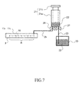
- a syringe pump 21 is arranged between the ink tank 20 and the recording heads 17a to 17c.
- the ink tank 20 and the syringe pump 21 are connected by a first supply channel 23 made of a tube member.
- the syringe pump 21 and the common channel 77 (see FIG. 6 ) in the recording heads 17a to 17c are each connected by a second supply channel 25 made of a tube member.
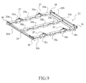
- FIG. 9 diagonally illustrates the carriage 31 that constitutes the wiping mechanism 30 according to the first embodiment.
- FIG. 10 diagonally illustrates the supporting frame 40 that constitutes the wiping mechanism 30 according to the first embodiment.
- the carriage 31 is formed as a frame body shape having first stays 32a and 32b, which slidably engage via the sliding rollers 36 on the rail portions 41a and 41b of the supporting frame 40, and second stays 33a, 33b and 33c, which are secured in a bridging-shape between the first stays 32a and 32b.
- the first wipers 35a to 35c are members to wipe off the ink discharged from the ink discharge nozzles 18 of the respective recording heads 17a to 17c.
- the first wipers 35a to 35c are brought into pressure contact from an approximately vertical direction on a wiping start position outside the nozzle region R (see FIG. 5 ) where nozzle faces of the ink discharge nozzles 18 are exposed.
- the first wipers 35a to 35c wipe the ink discharge face F including the nozzle region R.
- Gap rollers 37 are located on four locations of the top faces of the second stays 33a and 33c.
- the gap rollers 37 contact the head housing 10 of the recording unit 9 when lifting the wiping mechanism 30 to the recording unit 9 side in order to perform the wiping operation of the ink discharge faces F of the recording heads 17a to 17c by the first wipers 35a to 35c. This causes the first wipers 35a to 35c to keep a constant contact with the ink discharge faces F.
- an ink collecting tray 44 to collect the wiped waste ink on the ink discharge face F by the first wipers 35a to 35c is arranged on the top face of the supporting frame 40.
- a groove portion 44a is formed along the extending direction of the second stays 33a to 33c at the substantially central part of the ink collecting tray 44. Tray surfaces 44b and 44c at both sides across the groove portion 44a are formed in a downward pitch toward the groove portion 44a.
- An ink discharge hole 44d is located in the groove portion 44a, and the bottom of the groove portion 44a is in a form of downward pitch toward the ink discharge hole 44d.
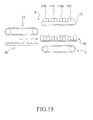
- FIG. 15 illustrates the state of the maintenance unit 19 positioned under the recording unit 9.
- FIG.16 illustrates a positional relationship between the recording heads 17a to 17c and the first wipers 35a to 35c when starting the wiping operation.
- FIG. 16 , and FIG. 17 , FIG. 18 and FIG. 23 to FIG. 25 which will be described later, illustrate a state of the recording unit 9 and the maintenance unit 19 viewed from the downstream side of the paper sheet conveyance direction (the left side of FIG. 15 ).
- the supporting frame 40 is simply illustrated plate-shaped, and only the bottom face 45a is illustrated for the unit housing 45.
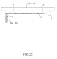
- the first wipers 35a to 35c are positioned at stop positions P (positions having a predetermined distance from the end portions of the nozzle regions R of the ink discharge faces F of the recording heads 17a to 17c). Specifically, the supporting frame 40 and the carriage 31 are lifted by rotating the shafts 50b of the elevating mechanism 50 so as to erect the lifting members 50a toward the arrow B direction as illustrated in FIG. 17 . A distance between the first wipers 35a to 35c and the ink discharge faces F is set to an enough space to cause the ink 22 discharged on the ink discharge faces F to be held between the ink discharge faces F and the upper end faces of the first wipers 35a to 35c.
- FIG.18 and FIG. 19 illustrate the recording heads 17a to 17c in a state where the ink 22 is discharged while each of the first wipers 35a to 35c is facing the near end portion of the nozzle region R.
- the ink 22 discharged from the ink discharge nozzles 18 contacts the upper end faces (counter faces) of the first wipers 35a to 35c.
- the ink 22 is discharged on the ink discharge face F along the shape of the nozzle region R where the ink discharge nozzles 18 exist.
- the discharged ink 22 contacts only a parts (the lower end side of FIG. 19 ) of the longitudinal direction of the first wipers 35a to 35c.
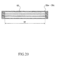
- FIG. 20 illustrates the upper end faces of the first wipers 35a to 35c.
- groove shaped concave portions 60 which are holding structures of the ink 22, are formed on the upper end faces of the first wipers 35a to 35c.
- the concave portions 60 are formed to have a length of equal to or more than the width W of the ink discharge face F along the longitudinal direction (the width direction of the ink discharge face F) of the first wipers 35a to 35c.
- this causes the ink 22 in contact with one end of the upper end face of the first wipers 35a to 35c to spread to the other end side along the concave portions 60 by a capillary phenomenon, as illustrated in FIG. 21 .
- the ink 22 is held in throughout the counter faces region of the upper end faces of the first wipers 35a to 35c and the ink discharge faces F.
- the ink 22 discharged on the ink discharge face F may drop or has a high viscosity as dryness progresses before contacting the first wipers 35a to 35c.
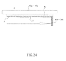
- FIG. 24 and FIG. 25 illustrate the recording heads 17a to 17c in a state where the respective first wipers 35a to 35c have moved to the end edge of the downstream side of the wiping direction of the ink discharge face F. As illustrated in FIG.
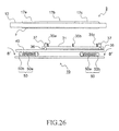
- the wiping operation to wipe off the ink 22 discharged on the ink discharge face F is performed. Specifically, as illustrated in FIG. 26 , rotating the shafts 50b of the elevating mechanism 50 to take down the lifting members 50a to the arrow B' direction lifts down the supporting frame 40 and the carriage 31. As a result, the first wipers 35a to 35c are retreated from the ink discharge face F of the recording heads 17a to 17c downward. Afterwards, as illustrated in FIG. 27 , the maintenance unit 19 is returned to the state of FIG. 16 again by rotating the input gear 43 in the reverse direction to move the carriage 31 to the arrow A' direction.
- the first wipers 35a to 35c move to the end portions of the downstream side of the ink discharge faces F of the respective recording heads 17a to 17c (the right end of FIG. 28 ). Subsequently, as illustrated in FIG. 26 and FIG. 27 , the first wipers 35a to 35c are retreated downward from the ink discharge faces F of the recording heads 17a to 17c. Then, the maintenance unit 19 is returned to the state of FIG. 16 by moving the carriage 31 to the arrow A' direction. Finally, the maintenance unit 19 positioned between the recording unit 9 and the first conveyance unit 5 is moved horizontally and is positioned under the second conveyance unit 12. The recovery operation of the recording heads 17a to 17c is complete by lifting the first conveyance unit 5 to a predetermined position.
- a first conveyance unit 5 positioned to face the inferior face of the recording unit 9 is lifted down as illustrated in FIG. 15 .
- the cap unit 90 positioned under the second conveyance unit 12 is then moved horizontally between the recording unit 9 and the first conveyance unit 5, so as to position the cap unit 90 to the position facing the recording unit 9.
- FIG. 29 illustrates another configuration of the concave portions 60 formed on the upper end faces of the first wipers 35a to 35c.
- the concave portions 60 has a tapered shape gradually widened in its groove width from one end side of the longitudinal direction (the width direction of the ink discharge face F) of the first wipers 35a to 35c to the other end side.
- the concave portions 60 is formed to have a length of equal to or more than the width W of the ink discharge face F.
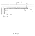
- moving the first wipers 35a to 35c from the state of FIG. 30 to the end edge of the upstream side of the wiping direction of the ink discharge face F applies and spreads the ink 22 over the whole ink discharge faces F of the upstream side (the left side of FIG. 31 ) from the stop positions P of the first wipers 35a to 35c as illustrated in FIG. 31 .
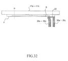
- moving the first wipers 35a to 35c to the end edge of the downstream side of the wiping direction of the ink discharge face F applies and spreads the ink 22 over the whole ink discharge faces F of the downstream side (the right side of FIG. 32 ) from the stop position P.
- the second wipers 39a to 39c arranged at the upstream side of the first wipers 35a to 35c in the wiping direction wipe off the ink 22 applied and spread by the first wipers 35a to 35c.
- a certain time may be required to re-disperse the dried mist in the ink 22.
- the ink 22 applied and spread by the first wipers 35a to 35c are immediately wiped off by the second wipers 39a to 39c.
- mist and paper dust adhered to the ink discharge faces F of the upstream side from the stop position P cannot be removed.
- mist and paper dust or similar adhered to the ink discharge face F of the downstream side from the stop position P can be removed more surely than before because the ink 22 is applied and spread over the whole ink discharge face F of the downstream side from the stop position P.
- the disclosure may also be applied to an ink-jet recording apparatus for monochromatic printing having only any one of the line heads 11C to 11K.
- the first wipers 35a to 35c which correspond to the recording heads 17a to 17c, are secured to the carriage 31. Effects of the disclosure will be further illustrated by the following examples.
- the testing machine includes the carriage 31 that moves to the approaching or separating direction with respect to the ink discharge faces F of the recording heads 17a to 17c as well as reciprocating along the ink discharge faces F and attached rubber blades made of EPDM (Asker hardness 60, impact resilience about 60%) having a width of 30 mm, a height of 7 mm, and a thickness of 1.5 mm as used for the first wipers 35a to 35c.
- EPDM Asker hardness 60, impact resilience about 60%
- the recording heads 17a to 17c includes dot forming units with a structure illustrated in FIG. 6 .
- the pressurization chamber 75 has an area of 0.2 mm2, a width of 200 ⁇ m, and a depth of 100 ⁇ m.
- the nozzle channel 76 has a diameter of 200 ⁇ m and a length of 800 ⁇ m.
- the supply hole 79 has a diameter of 30 ⁇ m and a length of 40 ⁇ m.
- the ink discharge nozzle 18 has a length of 30 ⁇ m.
- the discharge port 18a has a circular shape with a radius of 10 ⁇ m.
- the recording head where the dot forming units of the above configuration of 166 sets in one row on the ink discharge face F and 664 sets in total (four rows) were located was prepared.
- the ink discharge nozzles 18 have a pitch of 150 dpi in the same row is, while the pitch as a whole is 600 dpi by shifting one-quarter of pitch neighboring each row.
- the ink 22 to be used is a water based ink having a composition composed of the items as described in Table 1. After agitating the respective components, the solution was pressure-filtrated by a filter of pore size of 5 ⁇ m to make the ink 22.
- Table 1 Materials Compounded amount [wt%] Pigment dispersion 25.0 Olefin 0.5 1, 3-butanediol 5.0 Triethylene glycol monobutyl ether 5.0 2-pyrrolidone 5.0 Glycerin 15.0 Ion exchanged water 47.5 Total 100.0
- the disclosure is applicable to an ink-jet recording apparatus that performs recording by discharging ink from the recording head.
- Use of the disclosure ensures an ink-jet recording apparatus with a recovery mechanism that can remove the dried mist and foreign object such as paper dust adhered to the ink discharge face of the recording head more surely and effectively suppress poor ink discharge and reduction in sealability when mounting the cap.
Landscapes
- Ink Jet (AREA)
Applications Claiming Priority (1)
| Application Number | Priority Date | Filing Date | Title |
|---|---|---|---|
| JP2013136605A JP5871860B2 (ja) | 2013-06-28 | 2013-06-28 | 記録ヘッドの回復機構及びそれを備えたインクジェット記録装置、並びに記録ヘッドの回復方法 |
Publications (3)
| Publication Number | Publication Date |
|---|---|
| EP2821231A2 true EP2821231A2 (de) | 2015-01-07 |
| EP2821231A3 EP2821231A3 (de) | 2015-12-16 |
| EP2821231B1 EP2821231B1 (de) | 2019-11-27 |
Family
ID=50979591
Family Applications (1)
| Application Number | Title | Priority Date | Filing Date |
|---|---|---|---|
| EP14173287.5A Active EP2821231B1 (de) | 2013-06-28 | 2014-06-20 | Tintenstrahlaufzeichnungsvorrichtung mit Rückgewinnungsvorrichtung eines Aufzeichnungskopfes |
Country Status (4)
| Country | Link |
|---|---|
| US (1) | US20150002579A1 (de) |
| EP (1) | EP2821231B1 (de) |
| JP (1) | JP5871860B2 (de) |
| CN (1) | CN104249562B (de) |
Cited By (1)
| Publication number | Priority date | Publication date | Assignee | Title |
|---|---|---|---|---|
| WO2016124256A1 (de) * | 2015-02-02 | 2016-08-11 | Padaluma Ink-Jet-Solutions Gmbh & Co. Kg | Single-pass-tintenstrahldrucker |
Families Citing this family (8)
| Publication number | Priority date | Publication date | Assignee | Title |
|---|---|---|---|---|
| JP5992556B2 (ja) * | 2015-02-19 | 2016-09-14 | 京セラドキュメントソリューションズ株式会社 | 記録ヘッドの回復システム及びそれを備えたインクジェット記録装置、並びに記録ヘッドの回復方法 |
| JP6319177B2 (ja) * | 2015-05-14 | 2018-05-09 | 京セラドキュメントソリューションズ株式会社 | 記録ヘッドの修復方法、及びインクジェット記録装置 |
| WO2017002857A1 (ja) * | 2015-07-01 | 2017-01-05 | 積水化学工業株式会社 | インクジェットヘッドのクリーニング装置及びインクジェット印刷装置 |
| JP2017024199A (ja) * | 2015-07-16 | 2017-02-02 | 富士通周辺機株式会社 | インクジェットプリンタ |
| US10259225B2 (en) * | 2017-01-06 | 2019-04-16 | Kyocera Document Solutions Inc. | Recording head and ink-jet recording apparatus provided with the same |
| US10245836B2 (en) * | 2017-03-14 | 2019-04-02 | Kyocera Document Solutions Inc. | Head cleaning mechanism and inkjet recording apparatus including the same |
| JP7420575B2 (ja) * | 2020-02-03 | 2024-01-23 | 理想科学工業株式会社 | ワイパ機構 |
| US11383525B2 (en) | 2020-06-10 | 2022-07-12 | Xerox Corporation | System and method for efficiently purging printheads |
Family Cites Families (12)
| Publication number | Priority date | Publication date | Assignee | Title |
|---|---|---|---|---|
| JP2006212863A (ja) * | 2005-02-02 | 2006-08-17 | Fuji Xerox Co Ltd | インクジェット記録装置、及びインクジェット記録ヘッドのノズル面の清掃方法 |
| KR100965573B1 (ko) * | 2005-06-20 | 2010-06-23 | 엘지디스플레이 주식회사 | 잉크젯 헤드의 세정장비 |
| JP2007230033A (ja) * | 2006-02-28 | 2007-09-13 | Fuji Xerox Co Ltd | 液滴吐出装置 |
| TWI556871B (zh) * | 2007-02-21 | 2016-11-11 | Musashi Engineering Inc | Ink jet forming method and coating apparatus |
| JP4765969B2 (ja) * | 2007-03-22 | 2011-09-07 | ブラザー工業株式会社 | インクジェット記録装置 |
| JP4989361B2 (ja) * | 2007-08-17 | 2012-08-01 | 富士フイルム株式会社 | メンテナンス装置及び液体吐出装置並びにノズル面メンテナンス方法 |
| JP2009220520A (ja) * | 2008-03-18 | 2009-10-01 | Fujifilm Corp | 液体吐出装置及び払拭方法 |
| JP5347527B2 (ja) * | 2008-05-23 | 2013-11-20 | 株式会社リコー | 画像形成装置、泡塗布装置 |
| JP2011011498A (ja) * | 2009-07-03 | 2011-01-20 | Ricoh Co Ltd | 画像形成装置 |
| WO2011142156A1 (ja) * | 2010-05-10 | 2011-11-17 | シャープ株式会社 | クリーニング装置およびインクジェット塗布装置 |
| US8678547B2 (en) * | 2010-09-03 | 2014-03-25 | Toshiba Tec Kabushiki Kaisha | Inkjet recording device, inkjet recording method, and inkjet head cleaning device |
| JP5723728B2 (ja) * | 2011-08-31 | 2015-05-27 | 富士フイルム株式会社 | 液体吐出装置 |
-
2013
- 2013-06-28 JP JP2013136605A patent/JP5871860B2/ja active Active
-
2014
- 2014-06-04 CN CN201410245134.XA patent/CN104249562B/zh active Active
- 2014-06-19 US US14/309,258 patent/US20150002579A1/en not_active Abandoned
- 2014-06-20 EP EP14173287.5A patent/EP2821231B1/de active Active
Non-Patent Citations (1)
| Title |
|---|
| None |
Cited By (2)
| Publication number | Priority date | Publication date | Assignee | Title |
|---|---|---|---|---|
| WO2016124256A1 (de) * | 2015-02-02 | 2016-08-11 | Padaluma Ink-Jet-Solutions Gmbh & Co. Kg | Single-pass-tintenstrahldrucker |
| US10252531B2 (en) | 2015-02-02 | 2019-04-09 | Padaluma Ink-Jet-Solutions Gmbh & Co. Kg | Single pass inkjet printer |
Also Published As
| Publication number | Publication date |
|---|---|
| CN104249562A (zh) | 2014-12-31 |
| JP2015009445A (ja) | 2015-01-19 |
| EP2821231B1 (de) | 2019-11-27 |
| EP2821231A3 (de) | 2015-12-16 |
| JP5871860B2 (ja) | 2016-03-01 |
| CN104249562B (zh) | 2016-11-23 |
| US20150002579A1 (en) | 2015-01-01 |
Similar Documents
| Publication | Publication Date | Title |
|---|---|---|
| EP2821231B1 (de) | Tintenstrahlaufzeichnungsvorrichtung mit Rückgewinnungsvorrichtung eines Aufzeichnungskopfes | |
| US8591001B2 (en) | Multicolor printhead maintenance station | |
| EP2586615B1 (de) | Tintenstrahlaufzeichnungsvorrichtung | |
| JP6311660B2 (ja) | インクジェット記録装置 | |
| US20150091980A1 (en) | Recording-head recovery system, ink-jet recording apparatus including the same, and recording-head recovery method | |
| US20090309918A1 (en) | Fluid ejecting apparatus | |
| JP6332020B2 (ja) | 記録ヘッドの回復システム及びそれを備えたインクジェット記録装置 | |
| JP2009269327A (ja) | インクジェット記録装置 | |
| JP6112727B2 (ja) | 記録ヘッドの回復機構及びそれを備えたインクジェット記録装置、並びに記録ヘッドの回復方法 | |
| JP5987075B2 (ja) | インクジェット記録装置 | |
| JP6221946B2 (ja) | 記録ヘッドの回復システム及びそれを備えたインクジェット記録装置、並びに記録ヘッドの回復方法 | |
| JP6340924B2 (ja) | 記録ヘッドの回復システム及びそれを備えたインクジェット記録装置、並びに記録ヘッドの回復方法 | |
| JP2018118441A (ja) | 記録ヘッドの回復システム及びそれを備えたインクジェット記録装置 | |
| JP6265164B2 (ja) | 記録ヘッドの回復システム及びそれを備えたインクジェット記録装置、並びに記録ヘッドの回復方法 | |
| JP6112726B2 (ja) | 記録ヘッドの回復機構及びそれを備えたインクジェット記録装置、並びに記録ヘッドの回復方法 | |
| JP6180389B2 (ja) | 記録ヘッドの回復システム及びそれを備えたインクジェット記録装置、並びに記録ヘッドの回復方法 | |
| JP6579090B2 (ja) | 記録ヘッド及びそれを備えたインクジェット記録装置 | |
| JP2016101698A (ja) | 記録ヘッドの回復システム及びそれを備えたインクジェット記録装置 | |
| JP2018114666A (ja) | ヘッドクリーニング機構およびそれを備えたインクジェット記録装置 | |
| JP2016124256A (ja) | 記録ヘッド及びそれを備えたインクジェット記録装置 | |
| JP2008296555A (ja) | 画像記録装置のメンテナンス装置及びその方法 | |
| JP2018149756A (ja) | ヘッドクリーニング機構およびそれを備えたインクジェット記録装置 | |
| JP2018130931A (ja) | ヘッドクリーニング機構及びそれを備えたインクジェット記録装置 |
Legal Events
| Date | Code | Title | Description |
|---|---|---|---|
| PUAI | Public reference made under article 153(3) epc to a published international application that has entered the european phase |
Free format text: ORIGINAL CODE: 0009012 |
|
| 17P | Request for examination filed |
Effective date: 20140620 |
|
| AK | Designated contracting states |
Kind code of ref document: A2 Designated state(s): AL AT BE BG CH CY CZ DE DK EE ES FI FR GB GR HR HU IE IS IT LI LT LU LV MC MK MT NL NO PL PT RO RS SE SI SK SM TR |
|
| AX | Request for extension of the european patent |
Extension state: BA ME |
|
| PUAL | Search report despatched |
Free format text: ORIGINAL CODE: 0009013 |
|
| AK | Designated contracting states |
Kind code of ref document: A3 Designated state(s): AL AT BE BG CH CY CZ DE DK EE ES FI FR GB GR HR HU IE IS IT LI LT LU LV MC MK MT NL NO PL PT RO RS SE SI SK SM TR |
|
| AX | Request for extension of the european patent |
Extension state: BA ME |
|
| RIC1 | Information provided on ipc code assigned before grant |
Ipc: B41J 2/165 20060101AFI20151109BHEP |
|
| R17P | Request for examination filed (corrected) |
Effective date: 20160523 |
|
| RBV | Designated contracting states (corrected) |
Designated state(s): AL AT BE BG CH CY CZ DE DK EE ES FI FR GB GR HR HU IE IS IT LI LT LU LV MC MK MT NL NO PL PT RO RS SE SI SK SM TR |
|
| STAA | Information on the status of an ep patent application or granted ep patent |
Free format text: STATUS: EXAMINATION IS IN PROGRESS |
|
| 17Q | First examination report despatched |
Effective date: 20181022 |
|
| GRAP | Despatch of communication of intention to grant a patent |
Free format text: ORIGINAL CODE: EPIDOSNIGR1 |
|
| STAA | Information on the status of an ep patent application or granted ep patent |
Free format text: STATUS: GRANT OF PATENT IS INTENDED |
|
| INTG | Intention to grant announced |
Effective date: 20190617 |
|
| GRAS | Grant fee paid |
Free format text: ORIGINAL CODE: EPIDOSNIGR3 |
|
| GRAA | (expected) grant |
Free format text: ORIGINAL CODE: 0009210 |
|
| STAA | Information on the status of an ep patent application or granted ep patent |
Free format text: STATUS: THE PATENT HAS BEEN GRANTED |
|
| AK | Designated contracting states |
Kind code of ref document: B1 Designated state(s): AL AT BE BG CH CY CZ DE DK EE ES FI FR GB GR HR HU IE IS IT LI LT LU LV MC MK MT NL NO PL PT RO RS SE SI SK SM TR |
|
| REG | Reference to a national code |
Ref country code: GB Ref legal event code: FG4D |
|
| REG | Reference to a national code |
Ref country code: CH Ref legal event code: EP |
|
| REG | Reference to a national code |
Ref country code: AT Ref legal event code: REF Ref document number: 1206219 Country of ref document: AT Kind code of ref document: T Effective date: 20191215 |
|
| REG | Reference to a national code |
Ref country code: DE Ref legal event code: R096 Ref document number: 602014057390 Country of ref document: DE |
|
| REG | Reference to a national code |
Ref country code: IE Ref legal event code: FG4D |
|
| REG | Reference to a national code |
Ref country code: NL Ref legal event code: MP Effective date: 20191127 |
|
| REG | Reference to a national code |
Ref country code: LT Ref legal event code: MG4D |
|
| PG25 | Lapsed in a contracting state [announced via postgrant information from national office to epo] |
Ref country code: ES Free format text: LAPSE BECAUSE OF FAILURE TO SUBMIT A TRANSLATION OF THE DESCRIPTION OR TO PAY THE FEE WITHIN THE PRESCRIBED TIME-LIMIT Effective date: 20191127 Ref country code: LV Free format text: LAPSE BECAUSE OF FAILURE TO SUBMIT A TRANSLATION OF THE DESCRIPTION OR TO PAY THE FEE WITHIN THE PRESCRIBED TIME-LIMIT Effective date: 20191127 Ref country code: SE Free format text: LAPSE BECAUSE OF FAILURE TO SUBMIT A TRANSLATION OF THE DESCRIPTION OR TO PAY THE FEE WITHIN THE PRESCRIBED TIME-LIMIT Effective date: 20191127 Ref country code: NL Free format text: LAPSE BECAUSE OF FAILURE TO SUBMIT A TRANSLATION OF THE DESCRIPTION OR TO PAY THE FEE WITHIN THE PRESCRIBED TIME-LIMIT Effective date: 20191127 Ref country code: GR Free format text: LAPSE BECAUSE OF FAILURE TO SUBMIT A TRANSLATION OF THE DESCRIPTION OR TO PAY THE FEE WITHIN THE PRESCRIBED TIME-LIMIT Effective date: 20200228 Ref country code: NO Free format text: LAPSE BECAUSE OF FAILURE TO SUBMIT A TRANSLATION OF THE DESCRIPTION OR TO PAY THE FEE WITHIN THE PRESCRIBED TIME-LIMIT Effective date: 20200227 Ref country code: BG Free format text: LAPSE BECAUSE OF FAILURE TO SUBMIT A TRANSLATION OF THE DESCRIPTION OR TO PAY THE FEE WITHIN THE PRESCRIBED TIME-LIMIT Effective date: 20200227 Ref country code: FI Free format text: LAPSE BECAUSE OF FAILURE TO SUBMIT A TRANSLATION OF THE DESCRIPTION OR TO PAY THE FEE WITHIN THE PRESCRIBED TIME-LIMIT Effective date: 20191127 Ref country code: LT Free format text: LAPSE BECAUSE OF FAILURE TO SUBMIT A TRANSLATION OF THE DESCRIPTION OR TO PAY THE FEE WITHIN THE PRESCRIBED TIME-LIMIT Effective date: 20191127 |
|
| PG25 | Lapsed in a contracting state [announced via postgrant information from national office to epo] |
Ref country code: RS Free format text: LAPSE BECAUSE OF FAILURE TO SUBMIT A TRANSLATION OF THE DESCRIPTION OR TO PAY THE FEE WITHIN THE PRESCRIBED TIME-LIMIT Effective date: 20191127 Ref country code: IS Free format text: LAPSE BECAUSE OF FAILURE TO SUBMIT A TRANSLATION OF THE DESCRIPTION OR TO PAY THE FEE WITHIN THE PRESCRIBED TIME-LIMIT Effective date: 20200327 Ref country code: HR Free format text: LAPSE BECAUSE OF FAILURE TO SUBMIT A TRANSLATION OF THE DESCRIPTION OR TO PAY THE FEE WITHIN THE PRESCRIBED TIME-LIMIT Effective date: 20191127 |
|
| PG25 | Lapsed in a contracting state [announced via postgrant information from national office to epo] |
Ref country code: AL Free format text: LAPSE BECAUSE OF FAILURE TO SUBMIT A TRANSLATION OF THE DESCRIPTION OR TO PAY THE FEE WITHIN THE PRESCRIBED TIME-LIMIT Effective date: 20191127 |
|
| PG25 | Lapsed in a contracting state [announced via postgrant information from national office to epo] |
Ref country code: RO Free format text: LAPSE BECAUSE OF FAILURE TO SUBMIT A TRANSLATION OF THE DESCRIPTION OR TO PAY THE FEE WITHIN THE PRESCRIBED TIME-LIMIT Effective date: 20191127 Ref country code: PT Free format text: LAPSE BECAUSE OF FAILURE TO SUBMIT A TRANSLATION OF THE DESCRIPTION OR TO PAY THE FEE WITHIN THE PRESCRIBED TIME-LIMIT Effective date: 20200419 Ref country code: EE Free format text: LAPSE BECAUSE OF FAILURE TO SUBMIT A TRANSLATION OF THE DESCRIPTION OR TO PAY THE FEE WITHIN THE PRESCRIBED TIME-LIMIT Effective date: 20191127 Ref country code: DK Free format text: LAPSE BECAUSE OF FAILURE TO SUBMIT A TRANSLATION OF THE DESCRIPTION OR TO PAY THE FEE WITHIN THE PRESCRIBED TIME-LIMIT Effective date: 20191127 Ref country code: CZ Free format text: LAPSE BECAUSE OF FAILURE TO SUBMIT A TRANSLATION OF THE DESCRIPTION OR TO PAY THE FEE WITHIN THE PRESCRIBED TIME-LIMIT Effective date: 20191127 |
|
| REG | Reference to a national code |
Ref country code: DE Ref legal event code: R097 Ref document number: 602014057390 Country of ref document: DE |
|
| PG25 | Lapsed in a contracting state [announced via postgrant information from national office to epo] |
Ref country code: SM Free format text: LAPSE BECAUSE OF FAILURE TO SUBMIT A TRANSLATION OF THE DESCRIPTION OR TO PAY THE FEE WITHIN THE PRESCRIBED TIME-LIMIT Effective date: 20191127 Ref country code: SK Free format text: LAPSE BECAUSE OF FAILURE TO SUBMIT A TRANSLATION OF THE DESCRIPTION OR TO PAY THE FEE WITHIN THE PRESCRIBED TIME-LIMIT Effective date: 20191127 |
|
| REG | Reference to a national code |
Ref country code: AT Ref legal event code: MK05 Ref document number: 1206219 Country of ref document: AT Kind code of ref document: T Effective date: 20191127 |
|
| PLBE | No opposition filed within time limit |
Free format text: ORIGINAL CODE: 0009261 |
|
| STAA | Information on the status of an ep patent application or granted ep patent |
Free format text: STATUS: NO OPPOSITION FILED WITHIN TIME LIMIT |
|
| 26N | No opposition filed |
Effective date: 20200828 |
|
| PG25 | Lapsed in a contracting state [announced via postgrant information from national office to epo] |
Ref country code: SI Free format text: LAPSE BECAUSE OF FAILURE TO SUBMIT A TRANSLATION OF THE DESCRIPTION OR TO PAY THE FEE WITHIN THE PRESCRIBED TIME-LIMIT Effective date: 20191127 Ref country code: PL Free format text: LAPSE BECAUSE OF FAILURE TO SUBMIT A TRANSLATION OF THE DESCRIPTION OR TO PAY THE FEE WITHIN THE PRESCRIBED TIME-LIMIT Effective date: 20191127 Ref country code: AT Free format text: LAPSE BECAUSE OF FAILURE TO SUBMIT A TRANSLATION OF THE DESCRIPTION OR TO PAY THE FEE WITHIN THE PRESCRIBED TIME-LIMIT Effective date: 20191127 |
|
| PG25 | Lapsed in a contracting state [announced via postgrant information from national office to epo] |
Ref country code: IT Free format text: LAPSE BECAUSE OF FAILURE TO SUBMIT A TRANSLATION OF THE DESCRIPTION OR TO PAY THE FEE WITHIN THE PRESCRIBED TIME-LIMIT Effective date: 20191127 Ref country code: MC Free format text: LAPSE BECAUSE OF FAILURE TO SUBMIT A TRANSLATION OF THE DESCRIPTION OR TO PAY THE FEE WITHIN THE PRESCRIBED TIME-LIMIT Effective date: 20191127 |
|
| REG | Reference to a national code |
Ref country code: CH Ref legal event code: PL |
|
| PG25 | Lapsed in a contracting state [announced via postgrant information from national office to epo] |
Ref country code: LU Free format text: LAPSE BECAUSE OF NON-PAYMENT OF DUE FEES Effective date: 20200620 |
|
| REG | Reference to a national code |
Ref country code: BE Ref legal event code: MM Effective date: 20200630 |
|
| PG25 | Lapsed in a contracting state [announced via postgrant information from national office to epo] |
Ref country code: IE Free format text: LAPSE BECAUSE OF NON-PAYMENT OF DUE FEES Effective date: 20200620 Ref country code: LI Free format text: LAPSE BECAUSE OF NON-PAYMENT OF DUE FEES Effective date: 20200630 Ref country code: CH Free format text: LAPSE BECAUSE OF NON-PAYMENT OF DUE FEES Effective date: 20200630 |
|
| PG25 | Lapsed in a contracting state [announced via postgrant information from national office to epo] |
Ref country code: BE Free format text: LAPSE BECAUSE OF NON-PAYMENT OF DUE FEES Effective date: 20200630 |
|
| PG25 | Lapsed in a contracting state [announced via postgrant information from national office to epo] |
Ref country code: TR Free format text: LAPSE BECAUSE OF FAILURE TO SUBMIT A TRANSLATION OF THE DESCRIPTION OR TO PAY THE FEE WITHIN THE PRESCRIBED TIME-LIMIT Effective date: 20191127 Ref country code: MT Free format text: LAPSE BECAUSE OF FAILURE TO SUBMIT A TRANSLATION OF THE DESCRIPTION OR TO PAY THE FEE WITHIN THE PRESCRIBED TIME-LIMIT Effective date: 20191127 Ref country code: CY Free format text: LAPSE BECAUSE OF FAILURE TO SUBMIT A TRANSLATION OF THE DESCRIPTION OR TO PAY THE FEE WITHIN THE PRESCRIBED TIME-LIMIT Effective date: 20191127 |
|
| PG25 | Lapsed in a contracting state [announced via postgrant information from national office to epo] |
Ref country code: MK Free format text: LAPSE BECAUSE OF FAILURE TO SUBMIT A TRANSLATION OF THE DESCRIPTION OR TO PAY THE FEE WITHIN THE PRESCRIBED TIME-LIMIT Effective date: 20191127 |
|
| P01 | Opt-out of the competence of the unified patent court (upc) registered |
Effective date: 20230420 |
|
| PGFP | Annual fee paid to national office [announced via postgrant information from national office to epo] |
Ref country code: GB Payment date: 20240521 Year of fee payment: 11 |
|
| PGFP | Annual fee paid to national office [announced via postgrant information from national office to epo] |
Ref country code: DE Payment date: 20240521 Year of fee payment: 11 |
|
| PGFP | Annual fee paid to national office [announced via postgrant information from national office to epo] |
Ref country code: FR Payment date: 20240522 Year of fee payment: 11 |
|
| REG | Reference to a national code |
Ref country code: DE Ref legal event code: R119 Ref document number: 602014057390 Country of ref document: DE |
|
| GBPC | Gb: european patent ceased through non-payment of renewal fee |
Effective date: 20250620 |
|
| PG25 | Lapsed in a contracting state [announced via postgrant information from national office to epo] |
Ref country code: GB Free format text: LAPSE BECAUSE OF NON-PAYMENT OF DUE FEES Effective date: 20250620 |
|
| PG25 | Lapsed in a contracting state [announced via postgrant information from national office to epo] |
Ref country code: DE Free format text: LAPSE BECAUSE OF NON-PAYMENT OF DUE FEES Effective date: 20260101 |
|
| PG25 | Lapsed in a contracting state [announced via postgrant information from national office to epo] |
Ref country code: FR Free format text: LAPSE BECAUSE OF NON-PAYMENT OF DUE FEES Effective date: 20250630 |