EP2816716B1 - Vehicle drive control device - Google Patents
Vehicle drive control device Download PDFInfo
- Publication number
- EP2816716B1 EP2816716B1 EP13748560.3A EP13748560A EP2816716B1 EP 2816716 B1 EP2816716 B1 EP 2816716B1 EP 13748560 A EP13748560 A EP 13748560A EP 2816716 B1 EP2816716 B1 EP 2816716B1
- Authority
- EP
- European Patent Office
- Prior art keywords
- frame
- drive control
- control equipment
- power unit
- equipment according
- Prior art date
- Legal status (The legal status is an assumption and is not a legal conclusion. Google has not performed a legal analysis and makes no representation as to the accuracy of the status listed.)
- Active
Links
- 239000003990 capacitor Substances 0.000 claims description 28
- 238000006243 chemical reaction Methods 0.000 claims description 18
- 239000004065 semiconductor Substances 0.000 claims description 18
- 238000001816 cooling Methods 0.000 claims description 13
- 238000010276 construction Methods 0.000 description 26
- 238000004519 manufacturing process Methods 0.000 description 7
- 238000009434 installation Methods 0.000 description 6
- 239000000370 acceptor Substances 0.000 description 5
- 230000008878 coupling Effects 0.000 description 4
- 238000010168 coupling process Methods 0.000 description 4
- 238000005859 coupling reaction Methods 0.000 description 4
- 238000010586 diagram Methods 0.000 description 4
- 238000007689 inspection Methods 0.000 description 4
- 239000012212 insulator Substances 0.000 description 4
- 238000012423 maintenance Methods 0.000 description 4
- 230000001360 synchronised effect Effects 0.000 description 4
- 239000004593 Epoxy Substances 0.000 description 3
- 229910052581 Si3N4 Inorganic materials 0.000 description 3
- 229910052782 aluminium Inorganic materials 0.000 description 3
- XAGFODPZIPBFFR-UHFFFAOYSA-N aluminium Chemical compound [Al] XAGFODPZIPBFFR-UHFFFAOYSA-N 0.000 description 3
- 239000004020 conductor Substances 0.000 description 3
- 239000000463 material Substances 0.000 description 3
- 230000002093 peripheral effect Effects 0.000 description 3
- HQVNEWCFYHHQES-UHFFFAOYSA-N silicon nitride Chemical compound N12[Si]34N5[Si]62N3[Si]51N64 HQVNEWCFYHHQES-UHFFFAOYSA-N 0.000 description 3
- 230000003321 amplification Effects 0.000 description 2
- 238000003780 insertion Methods 0.000 description 2
- 230000037431 insertion Effects 0.000 description 2
- 238000003199 nucleic acid amplification method Methods 0.000 description 2
- 230000002787 reinforcement Effects 0.000 description 2
- 239000000725 suspension Substances 0.000 description 2
- 230000005856 abnormality Effects 0.000 description 1
- 238000004378 air conditioning Methods 0.000 description 1
- 239000000470 constituent Substances 0.000 description 1
- 230000000694 effects Effects 0.000 description 1
- 239000004519 grease Substances 0.000 description 1
- 238000009499 grossing Methods 0.000 description 1
- 230000006698 induction Effects 0.000 description 1
- 229910052751 metal Inorganic materials 0.000 description 1
- 239000002184 metal Substances 0.000 description 1
- 238000012856 packing Methods 0.000 description 1
- 230000003014 reinforcing effect Effects 0.000 description 1
- 238000005549 size reduction Methods 0.000 description 1
- 238000004078 waterproofing Methods 0.000 description 1
Images


Classifications
-
- B—PERFORMING OPERATIONS; TRANSPORTING
- B61—RAILWAYS
- B61C—LOCOMOTIVES; MOTOR RAILCARS
- B61C17/00—Arrangement or disposition of parts; Details or accessories not otherwise provided for; Use of control gear and control systems
- B61C17/12—Control gear; Arrangements for controlling locomotives from remote points in the train or when operating in multiple units
-
- B—PERFORMING OPERATIONS; TRANSPORTING
- B60—VEHICLES IN GENERAL
- B60L—PROPULSION OF ELECTRICALLY-PROPELLED VEHICLES; SUPPLYING ELECTRIC POWER FOR AUXILIARY EQUIPMENT OF ELECTRICALLY-PROPELLED VEHICLES; ELECTRODYNAMIC BRAKE SYSTEMS FOR VEHICLES IN GENERAL; MAGNETIC SUSPENSION OR LEVITATION FOR VEHICLES; MONITORING OPERATING VARIABLES OF ELECTRICALLY-PROPELLED VEHICLES; ELECTRIC SAFETY DEVICES FOR ELECTRICALLY-PROPELLED VEHICLES
- B60L15/00—Methods, circuits, or devices for controlling the traction-motor speed of electrically-propelled vehicles
- B60L15/007—Physical arrangements or structures of drive train converters specially adapted for the propulsion motors of electric vehicles
-
- B—PERFORMING OPERATIONS; TRANSPORTING
- B60—VEHICLES IN GENERAL
- B60L—PROPULSION OF ELECTRICALLY-PROPELLED VEHICLES; SUPPLYING ELECTRIC POWER FOR AUXILIARY EQUIPMENT OF ELECTRICALLY-PROPELLED VEHICLES; ELECTRODYNAMIC BRAKE SYSTEMS FOR VEHICLES IN GENERAL; MAGNETIC SUSPENSION OR LEVITATION FOR VEHICLES; MONITORING OPERATING VARIABLES OF ELECTRICALLY-PROPELLED VEHICLES; ELECTRIC SAFETY DEVICES FOR ELECTRICALLY-PROPELLED VEHICLES
- B60L3/00—Electric devices on electrically-propelled vehicles for safety purposes; Monitoring operating variables, e.g. speed, deceleration or energy consumption
- B60L3/0023—Detecting, eliminating, remedying or compensating for drive train abnormalities, e.g. failures within the drive train
- B60L3/003—Detecting, eliminating, remedying or compensating for drive train abnormalities, e.g. failures within the drive train relating to inverters
-
- B—PERFORMING OPERATIONS; TRANSPORTING
- B60—VEHICLES IN GENERAL
- B60L—PROPULSION OF ELECTRICALLY-PROPELLED VEHICLES; SUPPLYING ELECTRIC POWER FOR AUXILIARY EQUIPMENT OF ELECTRICALLY-PROPELLED VEHICLES; ELECTRODYNAMIC BRAKE SYSTEMS FOR VEHICLES IN GENERAL; MAGNETIC SUSPENSION OR LEVITATION FOR VEHICLES; MONITORING OPERATING VARIABLES OF ELECTRICALLY-PROPELLED VEHICLES; ELECTRIC SAFETY DEVICES FOR ELECTRICALLY-PROPELLED VEHICLES
- B60L50/00—Electric propulsion with power supplied within the vehicle
- B60L50/50—Electric propulsion with power supplied within the vehicle using propulsion power supplied by batteries or fuel cells
- B60L50/51—Electric propulsion with power supplied within the vehicle using propulsion power supplied by batteries or fuel cells characterised by AC-motors
-
- B—PERFORMING OPERATIONS; TRANSPORTING
- B60—VEHICLES IN GENERAL
- B60L—PROPULSION OF ELECTRICALLY-PROPELLED VEHICLES; SUPPLYING ELECTRIC POWER FOR AUXILIARY EQUIPMENT OF ELECTRICALLY-PROPELLED VEHICLES; ELECTRODYNAMIC BRAKE SYSTEMS FOR VEHICLES IN GENERAL; MAGNETIC SUSPENSION OR LEVITATION FOR VEHICLES; MONITORING OPERATING VARIABLES OF ELECTRICALLY-PROPELLED VEHICLES; ELECTRIC SAFETY DEVICES FOR ELECTRICALLY-PROPELLED VEHICLES
- B60L9/00—Electric propulsion with power supply external to the vehicle
- B60L9/32—Electric propulsion with power supply external to the vehicle using ac brush displacement motors
-
- B—PERFORMING OPERATIONS; TRANSPORTING
- B61—RAILWAYS
- B61C—LOCOMOTIVES; MOTOR RAILCARS
- B61C3/00—Electric locomotives or railcars
-
- H—ELECTRICITY
- H02—GENERATION; CONVERSION OR DISTRIBUTION OF ELECTRIC POWER
- H02M—APPARATUS FOR CONVERSION BETWEEN AC AND AC, BETWEEN AC AND DC, OR BETWEEN DC AND DC, AND FOR USE WITH MAINS OR SIMILAR POWER SUPPLY SYSTEMS; CONVERSION OF DC OR AC INPUT POWER INTO SURGE OUTPUT POWER; CONTROL OR REGULATION THEREOF
- H02M7/00—Conversion of ac power input into dc power output; Conversion of dc power input into ac power output
- H02M7/003—Constructional details, e.g. physical layout, assembly, wiring or busbar connections
-
- H—ELECTRICITY
- H02—GENERATION; CONVERSION OR DISTRIBUTION OF ELECTRIC POWER
- H02P—CONTROL OR REGULATION OF ELECTRIC MOTORS, ELECTRIC GENERATORS OR DYNAMO-ELECTRIC CONVERTERS; CONTROLLING TRANSFORMERS, REACTORS OR CHOKE COILS
- H02P27/00—Arrangements or methods for the control of AC motors characterised by the kind of supply voltage
- H02P27/04—Arrangements or methods for the control of AC motors characterised by the kind of supply voltage using variable-frequency supply voltage, e.g. inverter or converter supply voltage
- H02P27/06—Arrangements or methods for the control of AC motors characterised by the kind of supply voltage using variable-frequency supply voltage, e.g. inverter or converter supply voltage using dc to ac converters or inverters
-
- H—ELECTRICITY
- H05—ELECTRIC TECHNIQUES NOT OTHERWISE PROVIDED FOR
- H05K—PRINTED CIRCUITS; CASINGS OR CONSTRUCTIONAL DETAILS OF ELECTRIC APPARATUS; MANUFACTURE OF ASSEMBLAGES OF ELECTRICAL COMPONENTS
- H05K7/00—Constructional details common to different types of electric apparatus
- H05K7/14—Mounting supporting structure in casing or on frame or rack
- H05K7/1422—Printed circuit boards receptacles, e.g. stacked structures, electronic circuit modules or box like frames
- H05K7/1427—Housings
- H05K7/1432—Housings specially adapted for power drive units or power converters
- H05K7/14325—Housings specially adapted for power drive units or power converters for cabinets or racks
-
- H—ELECTRICITY
- H05—ELECTRIC TECHNIQUES NOT OTHERWISE PROVIDED FOR
- H05K—PRINTED CIRCUITS; CASINGS OR CONSTRUCTIONAL DETAILS OF ELECTRIC APPARATUS; MANUFACTURE OF ASSEMBLAGES OF ELECTRICAL COMPONENTS
- H05K7/00—Constructional details common to different types of electric apparatus
- H05K7/20—Modifications to facilitate cooling, ventilating, or heating
- H05K7/2089—Modifications to facilitate cooling, ventilating, or heating for power electronics, e.g. for inverters for controlling motor
- H05K7/209—Heat transfer by conduction from internal heat source to heat radiating structure
-
- B—PERFORMING OPERATIONS; TRANSPORTING
- B60—VEHICLES IN GENERAL
- B60L—PROPULSION OF ELECTRICALLY-PROPELLED VEHICLES; SUPPLYING ELECTRIC POWER FOR AUXILIARY EQUIPMENT OF ELECTRICALLY-PROPELLED VEHICLES; ELECTRODYNAMIC BRAKE SYSTEMS FOR VEHICLES IN GENERAL; MAGNETIC SUSPENSION OR LEVITATION FOR VEHICLES; MONITORING OPERATING VARIABLES OF ELECTRICALLY-PROPELLED VEHICLES; ELECTRIC SAFETY DEVICES FOR ELECTRICALLY-PROPELLED VEHICLES
- B60L2200/00—Type of vehicles
- B60L2200/26—Rail vehicles
-
- B—PERFORMING OPERATIONS; TRANSPORTING
- B60—VEHICLES IN GENERAL
- B60L—PROPULSION OF ELECTRICALLY-PROPELLED VEHICLES; SUPPLYING ELECTRIC POWER FOR AUXILIARY EQUIPMENT OF ELECTRICALLY-PROPELLED VEHICLES; ELECTRODYNAMIC BRAKE SYSTEMS FOR VEHICLES IN GENERAL; MAGNETIC SUSPENSION OR LEVITATION FOR VEHICLES; MONITORING OPERATING VARIABLES OF ELECTRICALLY-PROPELLED VEHICLES; ELECTRIC SAFETY DEVICES FOR ELECTRICALLY-PROPELLED VEHICLES
- B60L2220/00—Electrical machine types; Structures or applications thereof
- B60L2220/10—Electrical machine types
- B60L2220/14—Synchronous machines
-
- B—PERFORMING OPERATIONS; TRANSPORTING
- B60—VEHICLES IN GENERAL
- B60L—PROPULSION OF ELECTRICALLY-PROPELLED VEHICLES; SUPPLYING ELECTRIC POWER FOR AUXILIARY EQUIPMENT OF ELECTRICALLY-PROPELLED VEHICLES; ELECTRODYNAMIC BRAKE SYSTEMS FOR VEHICLES IN GENERAL; MAGNETIC SUSPENSION OR LEVITATION FOR VEHICLES; MONITORING OPERATING VARIABLES OF ELECTRICALLY-PROPELLED VEHICLES; ELECTRIC SAFETY DEVICES FOR ELECTRICALLY-PROPELLED VEHICLES
- B60L2220/00—Electrical machine types; Structures or applications thereof
- B60L2220/40—Electrical machine applications
- B60L2220/44—Wheel Hub motors, i.e. integrated in the wheel hub
-
- B—PERFORMING OPERATIONS; TRANSPORTING
- B60—VEHICLES IN GENERAL
- B60L—PROPULSION OF ELECTRICALLY-PROPELLED VEHICLES; SUPPLYING ELECTRIC POWER FOR AUXILIARY EQUIPMENT OF ELECTRICALLY-PROPELLED VEHICLES; ELECTRODYNAMIC BRAKE SYSTEMS FOR VEHICLES IN GENERAL; MAGNETIC SUSPENSION OR LEVITATION FOR VEHICLES; MONITORING OPERATING VARIABLES OF ELECTRICALLY-PROPELLED VEHICLES; ELECTRIC SAFETY DEVICES FOR ELECTRICALLY-PROPELLED VEHICLES
- B60L2240/00—Control parameters of input or output; Target parameters
- B60L2240/10—Vehicle control parameters
- B60L2240/36—Temperature of vehicle components or parts
-
- B—PERFORMING OPERATIONS; TRANSPORTING
- B60—VEHICLES IN GENERAL
- B60L—PROPULSION OF ELECTRICALLY-PROPELLED VEHICLES; SUPPLYING ELECTRIC POWER FOR AUXILIARY EQUIPMENT OF ELECTRICALLY-PROPELLED VEHICLES; ELECTRODYNAMIC BRAKE SYSTEMS FOR VEHICLES IN GENERAL; MAGNETIC SUSPENSION OR LEVITATION FOR VEHICLES; MONITORING OPERATING VARIABLES OF ELECTRICALLY-PROPELLED VEHICLES; ELECTRIC SAFETY DEVICES FOR ELECTRICALLY-PROPELLED VEHICLES
- B60L2260/00—Operating Modes
- B60L2260/20—Drive modes; Transition between modes
- B60L2260/28—Four wheel or all wheel drive
-
- Y—GENERAL TAGGING OF NEW TECHNOLOGICAL DEVELOPMENTS; GENERAL TAGGING OF CROSS-SECTIONAL TECHNOLOGIES SPANNING OVER SEVERAL SECTIONS OF THE IPC; TECHNICAL SUBJECTS COVERED BY FORMER USPC CROSS-REFERENCE ART COLLECTIONS [XRACs] AND DIGESTS
- Y02—TECHNOLOGIES OR APPLICATIONS FOR MITIGATION OR ADAPTATION AGAINST CLIMATE CHANGE
- Y02T—CLIMATE CHANGE MITIGATION TECHNOLOGIES RELATED TO TRANSPORTATION
- Y02T10/00—Road transport of goods or passengers
- Y02T10/60—Other road transportation technologies with climate change mitigation effect
- Y02T10/64—Electric machine technologies in electromobility
-
- Y—GENERAL TAGGING OF NEW TECHNOLOGICAL DEVELOPMENTS; GENERAL TAGGING OF CROSS-SECTIONAL TECHNOLOGIES SPANNING OVER SEVERAL SECTIONS OF THE IPC; TECHNICAL SUBJECTS COVERED BY FORMER USPC CROSS-REFERENCE ART COLLECTIONS [XRACs] AND DIGESTS
- Y02—TECHNOLOGIES OR APPLICATIONS FOR MITIGATION OR ADAPTATION AGAINST CLIMATE CHANGE
- Y02T—CLIMATE CHANGE MITIGATION TECHNOLOGIES RELATED TO TRANSPORTATION
- Y02T10/00—Road transport of goods or passengers
- Y02T10/60—Other road transportation technologies with climate change mitigation effect
- Y02T10/70—Energy storage systems for electromobility, e.g. batteries
Definitions
- An embodiment of the present invention relates to drive control equipment for a rail vehicle.
- a rail vehicle is equipped with for example a plurality of motors that drive the vehicle (that is to say, wheels) and air conditioning equipment and the like, and drive control equipment that controls the motors.
- the drive control equipment comprises a power conversion device such as a converter that converts AC voltage supplied from the power source to DC voltage and outputs the DC voltage to a motor, or an inverter that converts DC voltage to three-phase AC voltage and outputs the three-phase AC voltage to a motor, and a control device that controls the power conversion device and the motors.
- the drive control equipment comprises for example a contactor or breaker connected between the power conversion device and the motor.
- the contactor opens and closes the connection of the power conversion device and the motor: it opens the connection for example on stoppage of operation by the drive control equipment or in the event of abnormality.
- Patent Reference 1 Japanese Patent Number 4297971
- Patent Reference 1 Japanese Patent Number 4297971
- Permanent magnet synchronous motors are being employed as motors for rail vehicles. Permanent magnet synchronous motors have the advantage of high efficiency, compared with induction motors. However, permanent magnet synchronous motors require a driving inverter for each motor. In the case of a rail vehicle, an arrangement is adopted in which each vehicle is driven by a group of a plurality of motors, so, in the drive control equipment used to drive the plurality of motors, the number of inverters required must be increased, together with increase in the number of elements and increase in the number of contactors. This results in large external dimensions and mass of the drive control equipment, increasing manufacturing costs. Other prior art inverters are known from US 2010/036555 A1 , DE 197 34 270 A1 , and JP 2010 284033 A .
- the present invention which is defined by the features of claim 1, was made in view of the foregoing, the problem of the invention being to provide drive control equipment for a rail vehicle in which increase in size of the equipment can be restricted and manufacturing costs can be reduced.
- vehicle drive control equipment for driving a plurality of motors provided in a vehicle has the following construction. Specifically, it comprises:
- FIG. 1 is a block diagram showing drive control equipment 10 installed on a floor frame of a rail vehicle 8 according to a first embodiment.
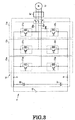
- FIG. 2 is a block diagram showing the entire construction of the drive control equipment schematically.
- drive control equipment 10 is placed between a rail vehicle 8 and the rails 7a, below the floor frame of the vehicle, and constitutes drive control equipment that drives a plurality of motors, for example four motors 12a to 12d (when there are a plurality of devices of the same type, if necessary, these will be indicated by the suffixes a, b, c, d, ...), that drive the wheels 7 of the rail vehicle.
- motors 12 for example permanent magnet synchronous motors are employed.
- the drive control equipment 10 comprises four power conversion devices, for example inverters (IV) 14a to 14d that are respectively connected with a single motor 12, four contactors 16 that are connected between the inverters and the motors 12, and a control device 18 that controls the inverters 14, the contactors 16 and the motors 12.
- inverters (IV) 14a to 14d that are respectively connected with a single motor 12
- contactors 16 that are connected between the inverters and the motors 12
- control device 18 that controls the inverters 14, the contactors 16 and the motors 12.
- each inverter 14 converts the DC power that is supplied from the DC power source 19 to AC power, which is then output to the motors 12.
- each inverter 14 is constituted as a two-level power conversion device and includes: a three-phase inverter circuit 11, a cooler, to be later described, that cools the semiconductor elements that constitute the inverter circuit, and a detector.
- the inverter circuit 11 has U-phase, V-phase and W-phase units.
- the U-phase unit 11u has first and second switching elements 21u, 22u, that are connected in series between the DC positive electrode terminal P and the DC negative electrode terminal N of the DC power source 19.
- the V-phase unit 11v has first and second switching elements 21v, 22v, that are connected in series between the DC positive electrode terminal P and the DC negative electrode terminal N;
- the W-phase unit 11w has first and second switching elements 21w, 22w, that are connected in series between the DC positive electrode terminal P and the DC negative electrode terminal N.
- the plurality of semiconductor switching elements comprises for example an IGBT (insulated gate bipolar transistor) or GTO or the like self-turn-off semiconductor element: for example, an IGBT and diode connected in anti-parallel with this IGBT may be embodied in modular form.
- the diode or IGBT in each switching element may be formed for example by an Si or silicon nitride (SiC) element, which is a low-loss semiconductor element.
- the U-phase unit 11U, V-phase unit 11V and W-phase unit 11W are connected in parallel; in addition, series-connected filter capacitors 26, 27 are connected in parallel with each unit.
- the filter capacitors 26, 27 are for example power source smoothing capacitors and may be aluminum dry capacitors or the like.
- An output terminal 30u is connected between the first switching elements 21u and the second switching element 22u of the U-phase unit 11U; an output terminal 30v is connected between the first switching element 21v and the second switching element 22v of the V-phase unit 11V; an output terminal 30w is connected between the first switching element 21w and the second switching element 22w of the W-phase unit 11W.
- the output terminals 30u, 30v, 30w of three-phase U, V, and W are connected with the motor 12 through a single contactor 16 and deliver three-phase AC output power to the motor 12.
- the first to fourth switching elements 21u, 22u, 21v, 22v, 21w, 22w of each phase referred to above are mounted on a heat-sink face of a heat-sink block constituting the cooler.
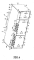
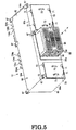
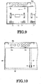
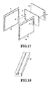
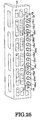
- FIG. 4 and FIG. 5 are perspective views showing an external view of the drive control equipment 10;
- FIG. 6 is a perspective view showing the internal construction of the drive control equipment with the equipment cover of the frame removed;
- FIG. 7 is a side view showing the internal construction of the drive control equipment with the equipment cover of the frame removed.
- the drive control equipment 10 comprises an elongate rectangular box-shaped frame 60.
- This frame 60 comprises: a plurality of rectangular frame-shaped main frames 61; an elongate rectangular ceiling wall 62 that is fixed to the main frame 61; an elongate rectangular bottom wall 63 that is parallel to and faces the ceiling wall that is fixed to the main frame 61; a pair of end walls 64a, 64b constituting both ends in the longitudinal direction of the frame, fixed to the main frame 61; and a pair of mutually facing sidewalls 65a, 65b that are fixed to the main frame so as to intersect with the end walls 64a, 64b at right angles.
- a plurality of suspension lugs 67 are mounted at the periphery of the ceiling wall 62 and the main frame 61.
- the frame 60 is stowed in the vehicle 8 by fixing these suspension lugs 67 to the side face below the body floor of the vehicle 8 (see FIG. 1 ).
- the ceiling wall 62 of the frame 60 faces the undersurface of the vehicle and the bottom wall 63 is positioned facing the ground surface and the side of a rail 7a.
- a plurality, for example three, of accommodating sections lined up in the longitudinal direction of the frame; these are: a first accommodating section (main accommodating section) 66a that is positioned in the middle; a second accommodating section (main accommodating section) 66b that is positioned at one end; and a third accommodating section (auxiliary accommodating section) 66c that is positioned at the other end.
- first accommodating section 66a of the frame body there are mainly accommodated four inverters and a power unit 68, to be later described; within the second accommodating section 66b, there is chiefly accommodated a control device 18; and within the auxiliary accommodating section 66c, there are chiefly accommodated four contactors 16.
- the pair of sidewalls 65a, 65b of the frame 60 have apertures facing the first, second and third accommodating sections 66a, 66b and 66c respectively: access to within the accommodating sections can be achieved through these apertures.
- the frame 60 is provided with a plurality of equipment covers 70 whereby the apertures of the sidewalls can be opened/closed: these are mounted in freely rotatable, removable fashion on the respective sidewalls 65a, 65b.
- Each of the equipment covers 70 is formed by a rectangular plate whose peripheral section is bent at the side of the frame 60: for example, the top edges of each of the equipment covers 70 are freely rotatably supported on the side wall 65a or the side wall 65b by two or three hinges 72. In this way, the equipment covers 70 cover the apertures of the sidewalls and can be rotated between a closed position in which they constitute part of the side wall and an open position in which the aperture is open.
- a locking lever 71 that locks the equipment cover in the closed position is provided at the side of the bottom wall 63 of each equipment cover 70.
- a handle 73 that is employed when opening/closing and detaching/attaching the equipment cover is provided in the middle of the equipment cover 70.
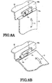
- each hinge 72 is provided with a pivot shaft 74a that is mounted on the sidewalls 65a, 65b of the frame 60 and a tubular acceptor 74b that is mounted on the equipment cover 70; the pivot shaft 74a is inserted in this acceptor 74b in a freely rotatable fashion and in a manner whereby it can be withdrawn along the axial direction. In this way, the acceptors 74b are freely rotatably supported on the pivot shaft 74a. Also, as shown in FIG. 8A, FIG. 8B , FIG. 9 and FIG.
- the equipment cover 70 can be removed from the frame 60 by withdrawing the acceptors 74b from the bearings (axes) 74a by sliding the equipment cover 70 along the axial direction of the bearing (axis) 74a.
- a construction of the hinge 72 could also be adopted in which the bearing (axis) 74a is mounted on the side of the equipment cover 70 and the acceptor 74b is mounted on the sidewall side of the frame.
- the frame 60 is provided with a stopper 74 to prevent unintended detachment of the equipment cover 70.
- the stopper 76 is formed by a metal plate that projects towards the side of the equipment cover 70 and is formed on the main frame 61. The stopper 76 engages the equipment cover when the equipment cover 70 that is closed in the closed position is moved in the withdrawal direction of the hinge 72, and thereby restricts movement of the equipment cover in the withdrawal direction. In this way, unintentional detachment of the equipment cover 70 can be reliably prevented. It should be noted that, by rotation of the equipment cover 70 towards the side of the open position, the stopper 76 becomes incapable of engagement with the equipment cover 70, so removal of the equipment cover 70 from the frame 60 can be achieved.
- stopper 76 need not necessarily be provided on the main frame 61, but could be provided on the equipment cover 70. In this case, when the equipment cover 70 is moved in the withdrawal direction, the stopper 76 comes into contact with the main frame 61, thereby restricting movement of the equipment cover.
- the drive control equipment 10 comprises a power unit 68 that is mounted in the frame 60 and whereof part is arranged within a first accommodating section 66a.
- the power unit 68 is fixed in the frame 60 by being detachably inserted into the frame 60 through an aperture of the sidewall 65b.
- the direction A of this detachable insertion is a direction orthogonal to the width direction of the frame 60 and the side wall 65a.
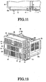
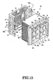
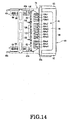
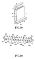
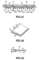
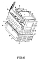
- FIG. 12 to FIG. 15 respectively show the power unit 68.
- the power unit 68 comprises: a base frame 78; a cooler 80; a plurality of semiconductor elements (first to fourth switching elements 20u to 23u, 20v to 23v, 20w to 23w, and first and second diodes 24u, 25u, 24v, 25v, 24w, 25w) constituting four inverters 14 that are mounted in the cooler 80; first control boards 82 having first connectors 81; and second control boards 84 having second connectors 83 connected with the first connectors.
- semiconductor elements first to fourth switching elements 20u to 23u, 20v to 23v, 20w to 23w, and first and second diodes 24u, 25u, 24v, 25v, 24w, 25w
- a base frame 78 comprises rectangular frames 85a and support frames 85b.
- the support frames 85b extend from the two side sections of the rectangular frames 85a in a direction (direction A of detachment/attachment of the power unit 68) orthogonal to the respective rectangular frames 85a.
- Handles 85c are mounted at the extension ends of the support frames 85b.
- a cooler 80 is provided with a rectangular plate-shaped cooling block 87 formed of material of high thermal conductivity such as for example aluminum, and a large number of radiating fins 86 that are erected on one side face of the cooling block 87; the cooling block 87 is fixed at its periphery to the rectangular frames 85a and is arranged within the rectangular frames 85a.
- the cooling block 87 is constituted so as to be integral with the radiating fins 86.
- the material of the radiating fins 86 is material of high conductivity, such as for example aluminum.
- the longitudinal direction of the large number of radiating fins 86 extends substantially parallel with the direction of travel of the vehicle 8 and the fins are lined up with prescribed gaps from the rail vehicle 8 in the direction of the rails 7a. Also, in a condition in which the power unit 68 is mounted in the frame 60, the radiating fins 86 project to outside the frame 60. Consequently, the traveling wind that is generated when the vehicle 8 travels can blow through between the radiating fins 86.
- the face of the cooling block 87 opposite to the face where the radiating fins 86 are mounted forms a heat-sink face 84b.
- a plurality of semiconductor elements (first to fourth switching elements 21u, 22u, 21v, 22v, 21w, 22w) are arranged on this heat-sink face 84b, lined up with mutual gaps, with heat-conducting grease or the like arranged between these and the heat-sink face.
- an elongate square pillar-shaped insulator 300 is fixed between a plurality of semiconductor elements on the heat-sink face 84b of the cooling block 87; PN input terminals 108, to be later described, are fixed, by for example screwing in, to this insulator.
- These PN input terminals 108 are connected with a plurality of semiconductor elements (first to fourth switching elements 21u, 22u, 21v, 22v, 21w, 22w).
- the provision of this insulator 300 ensures that, when any of the semiconductor elements fails, this failed semiconductor element is prevented from damaging other, normal semiconductor elements. Also, fixing of the insulator 300 makes it possible to prevent deformation etc of the PN input terminals 108.
- the power unit 68 is provided with a shroud (sometimes also called fin-cover) 88 of a shape such as to cover the radiating fins 86, in order to protect the radiating fins 86.
- This shroud (fin-cover) 88 is formed in substantially U shape by a rectangular front face section 88a and two rectangular side face sections 88b that are connected with both ends of the front face section 88a.
- the front face section 88a is located at the end on the opposite side to the end where the radiating fins 86 contact the cooling block 87 i.e. on the side of the end of the extension of the radiating fins 86; the side face 88b is located on the air inlet side and outlet side of the traveling wind of the radiating fins 86.
- This shroud (fin-cover) 88 is fixed by bolts or the like to the rectangular frames 85a of the base frame 78. Also, the shroud (fin-cover) 88 is provided with an aperture, at which the radiating fins 86 are left uncovered, on the side of the rail vehicle 8 and the rails 7a.
- the front face section 88a of the shroud (fin-cover) 88 is in mesh form, with the exception of the peripheral section thereof.
- two handles 90 and reinforcement ribs 91 to reinforce the periphery of these handles are provided on the front face section 88a.
- a large number of through-holes 92 for permitting passage of the traveling wind are formed in both side face sections 88b of the shroud (fin-cover) 88.
- These through-holes 92 are constituted for example by elongate slots extending in the direction of attachment/detachment of the power unit 68.
- a plurality of reinforcement ribs 93 extending in the attachment/detachment direction are provided in the side face sections 88b between the through-holes 92.
- the shroud (fin-cover) 88 is provided with a handle 90 and is provided with reinforcing ribs 91, 93 to enable it to withstand the attachment/detachment operation, owing to the construction whereby the shroud (fin-cover) 88 is open at the top end and bottom end of the radiating fins 86, increase in weight of the shroud (fin-cover) 88 can be suppressed. Also, in view of the fact that the radiating fins 86 are accessible to hand contact, their potential is set to earth potential.
- the two first control boards 88 that are connected with the semiconductor elements on the cooling block 87 will be described.
- the two first control boards 82 are mounted on the base frame 78, being arranged above and below on the side of the vehicle 8 and the side of the rails 7a, in a substantially parallel fashion so as to face the heat-sink face 84b of the cooling block 87.
- These first control boards 82 are for example gate amplification boards and are connected with the semiconductor elements of each inverter 14, so as to output switching signals.
- First connectors 81 are provided on the back face and the outer peripheral side of the first control boards 82.
- the two second control boards 84 having second connectors 83 that are connected with the aforementioned first connectors 81 will now be described.
- These second control boards 84 are for example gate control boards that output control signals to the gate amplification boards.
- the power unit 68 is provided with two second control boards 84: these second control boards 84 are respectively freely slidably mounted on two support frames 85b of the base frame 78.
- the second control boards 84 are mounted, with an insulating layer 95 therebetween on rectangular support boards (support base plates) 94 that are slightly larger than these second control boards 84. Also, as shown in FIG. 15 and FIG.
- a mesh-like cover 96 that covers the second control boards 84 is mounted on the support boards 94.
- one end of the support boards 94 is bent at right angles on the side of the second control board 84 and a handle 97 is mounted on this bent section.
- a second connector 83 is provided at the end of the second control board 84 on the opposite side to that of the handle 97.
- a pair of upper and lower guide rails 98 having a recess in the middle thereof are mounted on the support frames 85b of the base frame 78.
- the upper and lower guide rails 98 extend in the longitudinal direction of the support frames 85b and are positioned mutually parallel so that their recesses face each other.
- both side edges of the support boards 94 of the second control boards 84 engage with the recessed portions of the respective guide rails 98, so that they can be slid along the guide rails to the vicinity of the first control boards 82.
- the second control boards 84 are supported by the support frames 85b in such a way that they can be freely inserted or removed, by engagement with the recesses of the guide rails 98.
- the two second control boards 84 that are mounted along the guide rails 98 have second connectors 83 in mutually different positions, so as to be coupled with the first connectors 81 of the first control boards 82 that are positioned in the vertical direction on the side of the cooling block 87.
- the two second support boards 84 are arranged in an opposing fashion in a direction orthogonal to the first control boards 32 and in a manner such that a gap is left between these second support boards 84.
- the space in the second accommodating section can be effectively utilized by arranging the first control boards 82 and the second control boards 84 in mutually orthogonal directions. Also, inspection and maintenance of the first and second control boards 82, 84 can be facilitated by providing the second control board 84 in a direction orthogonal to the first control board 82 but without overlapping.
- connecting wiring or the like becomes unnecessary, making it possible to reduce the installation space and reduce manufacturing costs.
- the power unit 68 comprises a connector support frame 100 and output connectors 104u1 to 104w4.
- the connector support frame 100 is an elongate connector support frame that extends in the direction orthogonal to the direction A of attachment/detachment of the power unit 68 (i.e. direction parallel with the heat-sink face 84 of the cooler 80) .
- the output connectors 104u1 to 104w4 are mounted on the connector support frame 100 on either side of an insulating plate 102 made of for example epoxy.
- the connector support frame 100 and output connector are provided at the top of the power unit 68 i.e.
- the output connectors include: three output connectors 104u1, v1, w1; three output connectors 104u2, v2, w2; three output connectors 104u3, v3, w3 and three output connectors 104u4, v4, w4 that are respectively connected with the U, V, W outputs of the four inverters 14.
- These output connectors 104u1 to 104w4 are arranged in a row along the longitudinal direction of the connector support frame 100, with mutual gaps therebetween.
- a plurality of locating pins 106 are erected between the output connectors 104u1 to 104w4 of the connector support frame 100, and extend from the connector support frame in the direction A of attachment/detachment of the power unit 68. Locating pins 106 are respectively provided at one end of the row of output connectors and another end thereof, and between the output connectors 104w1, 104u2 and also between the output connectors 104w3, 104u4.
- the locating pin 106 engages with position-locating holes of the connector support frame provided on the side of the frame 60 and thereby positionally locates the output connectors 104u1 to 104w4 with respect to the connectors provided on the side of the frame 60; the output connectors 104u1 to 104w4 are then respectively fitted into the connectors on the side of the frame.
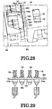
- the power unit 68 comprises PN input terminals 108 constituted by a DC positive electrode terminal P and a DC negative electrode terminal N, for supplying current to the inverters 14. These PN input terminals 108 are provided below the power unit 68 i.e. at the side of the bottom wall 63 of the frame 60. As shown in FIG. 22 and FIG. 23 , the PN input terminals 108 comprise a plate-shaped positive electrode terminal 110a and a plate-shaped negative electrode terminal 110b that is formed substantially of the same size as this positive electrode terminal; this positive electrode terminal 110a and negative electrode terminal 110b are mutually superimposed, gripping an insulating layer 112 therebetween, and extend mutually along the same direction.
- an insulating layer 112 formed by epoxy or the like has an area that is larger than that of the positive electrode terminal 110a and negative electrode terminal 110b and extends outwards by a prescribed width from the periphery of the positive electrode terminal 110a and negative electrode terminal 110b.
- the PN input terminals 108 are mounted for example on the base frame 78 and extend in the attachment/detachment direction A from this base frame, beyond the first control board 82. Thus the PN input terminals 108 extend substantially parallel with the bottom wall 63 of the frame 60.
- the PN input terminals 108 are constituted as connectors by adopting a construction wherein the positive electrode terminal 110a and the negative electrode terminal 110b are arranged in a mutually overlapping fashion and extend along each other for their entire length.
- These PN input terminals 108, constituted as connectors, can thus easily be slide-fitted onto coupling sections (connecting terminals 122) that are provided on the filter capacitors 26, 27.
- the inductance can be reduced by adopting a construction in which the positive electrode terminal 110a and negative electrode terminal 110b are arranged in a mutually overlapping fashion and extend mutually along their entire length.
- the filter capacitors 26, 27, that have coupling sections with the PN input terminals 108, as described above, will be described.
- the plurality of filter capacitors 26, 27 constituting the inverters 14 in the first accommodating section 66a of the frame 60 are arranged on the bottom wall 63.
- these filter capacitors 26, 27 have connecting terminals 122 that are capable of coupling with the PN input terminals 108 of the power unit 68.
- the filter capacitors 26, 27 are arranged so as to be located between the two second control boards 84 when the power unit 68 is mounted in the frame 60. Also, the filter capacitors 26, 27 are connected with the power source through high-voltage side connectors, to be later described.
- an elongate support frame 124 is provided within the first accommodating section 66a of the frame 60, and extends in a direction orthogonal to the direction A of attachment/detachment of the power unit 68.
- the connector support frame 124 is arranged adjacently in an opposed fashion, parallel with the connector support frame 100 of the power unit 68.
- a plurality of input connectors 126 are mounted on the connector support frame 124, sandwiching insulating plates 125 made of epoxy or the like.
- This plurality of input connectors 126u1 to 126w4 (three input connectors 126u1, v1, w1; three input connectors 126u2, v2, w2; three input connectors 126u3, v3, w3; and three input connectors 126u4, v4, w4) are arranged along the longitudinal direction of the connector support frame 124 lined up in a single row and with mutual gaps therebetween.
- the connectors that are coupled with these input connectors 126u1 to 126w4 are the output connectors 104u1 to 104w4. Also, as shown in FIG.
- a plurality of position location holes 128 are formed in the connector support frame 124 and an insulating plate 125.
- the position location holes 128 are respectively formed at the end of the row of input connectors and another end, between the input connectors 104w1, 104u2, and between the input connectors 104w3, 104u4.
- a plurality of conductors 130 are mounted on the connector support frame 124; the ends of each conductor are respectively connected with the input connectors 104u1 to 126w4. Also, the other ends of the plurality of conductors 130 are connected with a plurality of connectors 132 that are respectively provided on the side of the contactors 16; and, in addition, are connected with the plurality of contactors 16 through these connectors 132.
- the power unit 68 is inserted and mounted from a sidewall aperture of the frame 60 into the first accommodating section 66a of the frame 60.
- the locating pins 106 on the side of the power unit 68 are respectively inserted in the position location holes 128 of the connector support frame 124 on the side of the frame 60.
- the respective input connectors 126u1 to 126w4 on the side of the frame are located in position so as to face the output connectors 104u1 to 104w4 on the side of the power unit 68.
- the output connectors 104u1 to 104w4 on the side of the power unit 68 are respectively fitted into the input connectors 126u1 to 126w4 on the side of the frame 60, by further insertion of the power unit 68 as far as a prescribed position of the frame 60, following the guidance provided by the locating pins 106 and the position location holes 128.
- a conductive connection is achieved by engagement of the PN input terminals 108 of the power unit 68 with the connection terminals 122 of the filter capacitors 26, 27.
- the inverters 14 provided in the power unit 68 are connected with the respectively corresponding contactors 16 and connected with the power source 19 through the filter capacitors 26, 27 (connected with the power source through the pantograph, fuse and switch).
- the power unit 68 mounted in the frame 60 is arranged in the prescribed position by fixing the rectangular frames 85a to the side wall 65b of the frame 60 and the main frame 61.
- the radiating fins 86 and shroud (fin-cover) 88 of the power unit 68 are positioned outside the frame 60 so as to be capable of receiving the traveling wind of the vehicle.
- the other portions of the power unit 68 are arranged within the first accommodating section 66a of the frame 60.
- the two second control boards 84 that are mounted in the power unit 68 are arranged on both sides of the filter capacitors 26, 27 so that an efficient arrangement of the filter capacitors and the main frame 61 in the comparatively narrow space is achieved.
- extending ends of the second control boards 64 are arranged in the vicinity of the sidewalls 65a on the opposite side of the frame 60. Consequently, inspection and maintenance of the second control board 64 can be achieved from the aperture side of the sidewalls 65a and the second control boards 64 can be withdrawn/inserted with respect to the power unit 68, by removing the equipment cover 70.
- Miniaturization of the drive control equipment 10 can thus be achieved by reducing the installation space by efficient arrangement of the power unit 68 within the first accommodating section 66a. Also, maintenance and inspection of the power unit 68 can easily be performed. Furthermore, reduction in the size and weight of the power unit 68 can be achieved and the operation of detachment/attachment of the power unit 68 can be facilitated, by, of the elements constituting the inverter 14, placing the filter capacitors 26 and 27, which are of relatively large size and weight, on the bottom wall 63 of the frame 60, and arranging the other constituent elements of the inverter 14 in the power unit 68, so as to make it possible to connect these with the filter capacitors through connectors and output terminals.
- the high-voltage side connectors 134a, 134b, 134c, 134d are provided through the frame 60, facing the first accommodating section 66a and are directly connected with the outputs of the four contactors 16 by wirings 138 arranged in the frame 60.
- the high-voltage side connectors134a, 134b, 134c, 134d are for example screw-in type connectors; a link connector 140 connected with the motor 12 is connected and fixed thereto from the side of these high-voltage side connectors.
- the high-voltage side connectors 136a, 136b, 136c are arranged facing the second accommodating section 66b, so as to pass through the frame 60.
- the high-voltage side connector 136a is connected with wiring within the frame 60 and this wiring is directly connected with the filter capacitors 26, 27.
- the high-voltage side connectors 136a, 136b, 136c are for example screw-in type connectors; a link connector connected with a high-voltage line, not shown, is connected and fixed to these high-voltage side connectors.
- the need to provide a terminal block within the frame is obviated, and the installation space that needs to be provided within the frame can be reduced.
- waterproofing of these connectors can be achieved solely by means of rubber packing, so the need, as conventionally, to lead the wiring to the outside through the walls of the frame 60 and to seal these leading-out portions, is eliminated: thus improved ease of assembly, reduced manufacturing costs and reduced installation space can be achieved.
- the connectors need not necessarily be of the screw-in type, and connectors of other types, such as push-fit connectors could be employed.
- the control device 18 comprises various equipment accommodated in the second accommodating section 66b of the frame 60.
- the control device 18 comprises a plurality, for example three, of earthing capacitors 141; these earthing capacitors 141 are arranged on the inside face side of the ceiling wall 62 within the second accommodating section 66b.
- These earthing capacitors 141 may well constitute a source of noise and so are installed on the ceiling wall 62, and the high-voltage leads (lines), motor frame earth lead (line), or power unit earth lead (line) and other high-voltage or low-voltage leads (lines) or the like are arranged so as not to run in the same direction. In this way, the effect of noise from the earthing capacitors 141 on the control device 18 can be minimized.
- the four contactors 16 are arranged within the third accommodating section 66c of the frame 60.
- Two of the contactors 16 are arranged on the sidewall 65a and two of the contactors 16 are arranged on the sidewall 65b: these contactors are arranged parallel with each other in the vertical direction of the frame 60 (direction of the rail 7a from the vehicle 8).
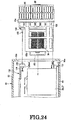
- FIG. 31 is a cross-sectional view showing diagrammatically drive control equipment according to a second embodiment.
- the frame 60 of the drive control equipment 10 is provided with a reflecting plate 150 that reflects an image of the connections of the PN input terminals of the power unit and the connection terminals of the filter capacitors to outside the frame.
- the surface of the reflecting plate 150 is formed for example as a mirror surface.
- the reflecting plate 150 is fixed for example to the inside face of the ceiling wall 62 of the frame 60.
- the mirror surface of the reflecting plate 150 is inclined with respect to the ceiling wall 62 and faces the aforementioned connections.
- an observation window 152 that transmits the image that is reflected by the reflecting plate 150 is formed in the ceiling wall 62. In this way, the connection conditions of the aforementioned connections can be ascertained through the observation window 152 from outside the frame 60, so locations that are difficult to inspect from outside, being deep within, can easily be inspected.
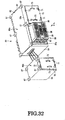
- FIG. 32 shows diagrammatically drive control equipment according to a third embodiment.
- the frame 60 for the drive control equipment 10 is divided into a first frame 60a having a first accommodating section that accommodates the inverter and power unit and a second accommodating section that accommodates a control device; and a second frame 60b having a third accommodating section that accommodates the contactors.
- the contactors 16 of the drive control equipment 10 can be installed independently in another location, so the degree of freedom in relation to the location of installation of the drive control equipment 10 can be increased.
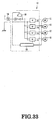
- FIG. 33 is a block diagram of the layout of drive control equipment 10 according to a fourth embodiment.
- the drive control equipment 10 comprises: four inverters respectively connected with four permanent magnet motors 12; a single contactor 16 connected in parallel between the power source 19 and the input side of these four inverters 14; and a control device 18 that controls the contactor 16 and the motors 12.
- Other aspects of the construction of the drive control equipment 10 are the same as in the case of the first embodiment described above.
- the contactors 16 can be reduced to a single contactor and size reduction of the drive control equipment 10 can thereby be achieved, making it possible to reduce manufacturing costs.
- drive control equipment can be provided in which increase in size can be suppressed and reduction in manufacturing costs can be achieved, in the same way as above.
- the present invention may be utilized in rail vehicles in which drive control equipment for controlling drive of a motor is mounted.
Landscapes
- Engineering & Computer Science (AREA)
- Power Engineering (AREA)
- Transportation (AREA)
- Mechanical Engineering (AREA)
- Life Sciences & Earth Sciences (AREA)
- Sustainable Energy (AREA)
- Sustainable Development (AREA)
- Microelectronics & Electronic Packaging (AREA)
- Physics & Mathematics (AREA)
- Thermal Sciences (AREA)
- Automation & Control Theory (AREA)
- Inverter Devices (AREA)
- Electric Propulsion And Braking For Vehicles (AREA)
- Combinations Of Printed Boards (AREA)
Applications Claiming Priority (2)
| Application Number | Priority Date | Filing Date | Title |
|---|---|---|---|
| JP2012028941A JP5749192B2 (ja) | 2012-02-13 | 2012-02-13 | 車両用駆動制御装置 |
| PCT/JP2013/000493 WO2013121719A1 (ja) | 2012-02-13 | 2013-01-30 | 車両用駆動制御装置 |
Publications (3)
| Publication Number | Publication Date |
|---|---|
| EP2816716A1 EP2816716A1 (en) | 2014-12-24 |
| EP2816716A4 EP2816716A4 (en) | 2015-10-07 |
| EP2816716B1 true EP2816716B1 (en) | 2017-10-11 |
Family
ID=48983859
Family Applications (1)
| Application Number | Title | Priority Date | Filing Date |
|---|---|---|---|
| EP13748560.3A Active EP2816716B1 (en) | 2012-02-13 | 2013-01-30 | Vehicle drive control device |
Country Status (8)
| Country | Link |
|---|---|
| US (1) | US9592739B2 (ja) |
| EP (1) | EP2816716B1 (ja) |
| JP (1) | JP5749192B2 (ja) |
| KR (1) | KR101616773B1 (ja) |
| CN (1) | CN104160608B (ja) |
| IN (1) | IN2014DN06732A (ja) |
| SG (1) | SG11201404894YA (ja) |
| WO (1) | WO2013121719A1 (ja) |
Cited By (1)
| Publication number | Priority date | Publication date | Assignee | Title |
|---|---|---|---|---|
| WO2024156405A1 (de) * | 2023-01-25 | 2024-08-02 | Siemens Mobility GmbH | Container in einem maschinenraum eines schienenfahrzeugs |
Families Citing this family (48)
| Publication number | Priority date | Publication date | Assignee | Title |
|---|---|---|---|---|
| JP5749192B2 (ja) * | 2012-02-13 | 2015-07-15 | 株式会社東芝 | 車両用駆動制御装置 |
| KR101655714B1 (ko) * | 2013-05-31 | 2016-09-07 | 아이신에이더블류 가부시키가이샤 | 차량용 구동 장치 |
| JP6169187B2 (ja) | 2013-12-03 | 2017-07-26 | 三菱電機株式会社 | 電力変換装置 |
| JP6322428B2 (ja) * | 2014-01-24 | 2018-05-09 | 日本電産サンキョー株式会社 | モータ駆動装置 |
| US9742305B2 (en) * | 2014-02-07 | 2017-08-22 | Mitsubishi Electric Corporation | Power conversion apparatus |
| CN104953792B (zh) * | 2014-03-25 | 2017-11-14 | 株洲南车时代电气股份有限公司 | 一种低地板车辆牵引变流器 |
| US9825437B2 (en) * | 2014-06-04 | 2017-11-21 | Hamilton Sundstrand Corporation | Three-dimensional power distribution interconnect structure |
| WO2015196214A1 (en) | 2014-06-20 | 2015-12-23 | General Electric Company | Apparatus and method for control of multi-inverter power converter |
| KR20170031128A (ko) * | 2014-07-09 | 2017-03-20 | 오클랜드 유니서비시즈 리미티드 | 전기 차량들에 적절한 유도 전력 시스템 |
| JP6376696B2 (ja) * | 2014-12-19 | 2018-08-22 | 東洋電機製造株式会社 | 鉄道車両用床下配置機器 |
| CN206914326U (zh) | 2015-01-08 | 2018-01-23 | 三菱电机株式会社 | 铁道车辆用冷却装置 |
| JP6421637B2 (ja) * | 2015-02-23 | 2018-11-14 | 株式会社明電舎 | インバータシステム |
| US9881912B2 (en) * | 2015-03-24 | 2018-01-30 | Kabushiki Kaisha Toshiba | Semiconductor device, inverter circuit, driving device, vehicle, and elevator |
| JP6345344B2 (ja) * | 2015-05-12 | 2018-06-20 | 三菱電機株式会社 | 車両用制御装置 |
| JP2017024505A (ja) * | 2015-07-21 | 2017-02-02 | 東洋電機製造株式会社 | 車両用駆動制御装置 |
| KR101821878B1 (ko) * | 2016-02-24 | 2018-01-24 | 엘에스산전 주식회사 | 인버터 |
| PL3216656T3 (pl) * | 2016-03-08 | 2018-12-31 | Siemens Aktiengesellschaft | Pojazd szynowy |
| US10787182B2 (en) | 2016-03-25 | 2020-09-29 | Mitsubishi Electric Corporation | Vehicle control device |
| EP3250016B1 (en) * | 2016-05-26 | 2019-07-17 | ABB Schweiz AG | Electrical device |
| CN106314453B (zh) * | 2016-08-26 | 2018-07-13 | 西安开天铁路电气股份有限公司 | 一种铁路电网检测机车司机控制器 |
| FR3058008B1 (fr) * | 2016-10-21 | 2018-10-19 | Valeo Equipements Electriques Moteur | Convertisseur de tension destine a alimenter en puissance une machine electrique pour vehicule automobile |
| JP6723141B2 (ja) | 2016-11-11 | 2020-07-15 | 三菱重工サーマルシステムズ株式会社 | コンデンサユニット、電動圧縮機 |
| JP6723142B2 (ja) | 2016-11-11 | 2020-07-15 | 三菱重工サーマルシステムズ株式会社 | コンデンサユニット、電動圧縮機 |
| FR3062771B1 (fr) * | 2017-02-08 | 2019-04-05 | Alstom Transport Technologies | Module electronique refroidi par convection forcee avec grille de distribution du flux d'air |
| FR3063177B1 (fr) * | 2017-02-17 | 2019-04-05 | Alstom Transport Technologies | Coffre ameliore pour un convertisseur d'alimentation en puissance electrique d'un moteur d'un vehicule guide |
| FR3063178B1 (fr) * | 2017-02-17 | 2019-04-05 | Alstom Transport Technologies | Coffre pour vehicule ferroviaire, et vehicule ferroviaire associe |
| JP6943066B2 (ja) * | 2017-08-14 | 2021-09-29 | 富士電機株式会社 | 電力変換装置 |
| US10850623B2 (en) | 2017-10-30 | 2020-12-01 | Sf Motors, Inc. | Stacked electric vehicle inverter cells |
| JP6637013B2 (ja) * | 2017-10-31 | 2020-01-29 | ファナック株式会社 | 制御装置 |
| DE102018105173B3 (de) * | 2018-03-07 | 2019-06-19 | Framatome Gmbh | Modular aufgebaute Einschubwandlereinheit sowie Leittechnikstromversorgungssystem für ein Kernkraftwerk |
| US10790758B2 (en) | 2018-03-08 | 2020-09-29 | Chongqing Jinkang New Energy Vehicle Co., Ltd. | Power converter for electric vehicle drive systems |
| US10756649B2 (en) | 2018-03-23 | 2020-08-25 | Chongqing Jinkang New Energy Vehicle Co., Ltd. | Inverter module having multiple half-bridge modules for a power converter of an electric vehicle |
| US10594230B2 (en) | 2018-03-23 | 2020-03-17 | Sf Motors, Inc. | Inverter module having multiple half-bridge modules for a power converter of an electric vehicle |
| US10779445B2 (en) | 2018-03-23 | 2020-09-15 | Chongqing Jinkang New Energy Vehicle Co., Ltd. | Inverter module having multiple half-bridge modules for a power converter of an electric vehicle |
| US10778117B2 (en) | 2018-04-17 | 2020-09-15 | Chongqing Jinkang New Energy Vehicle Co., Ltd. | Inverter module of an electric vehicle |
| US10772242B2 (en) | 2018-04-17 | 2020-09-08 | Chongqing Jinkang New Energy Vehicle Co., Ltd. | Inverter module of an electric vehicle |
| US10608423B2 (en) | 2018-04-26 | 2020-03-31 | Sf Motors, Inc. | Electric vehicle inverter module laminated bus bar |
| US10600578B2 (en) | 2018-04-26 | 2020-03-24 | Sf Motors, Inc. | Electric vehicle inverter module capacitors |
| US10660242B2 (en) * | 2018-04-26 | 2020-05-19 | Chongqing Jinkang New Energy Vehicle Co., Ltd. | Electric vehicle inverter module heat sink |
| DE112019002391T5 (de) * | 2018-06-22 | 2021-02-11 | Hitachi Automotive Systems, Ltd. | Leistungsumsetzungsvorrichtung |
| WO2020166472A1 (ja) * | 2019-02-13 | 2020-08-20 | 株式会社日立製作所 | 鉄道車両用の駆動装置、鉄道車両及びその製造方法 |
| FR3100422B1 (fr) * | 2019-09-04 | 2021-09-10 | Alstom Transp Tech | Dispositif à cartes électroniques avec dissipateur thermique |
| US11955906B2 (en) * | 2019-11-25 | 2024-04-09 | Aisin Corporation | Miniaturization of control boards with flexibility in desposition of parts and wiring |
| JP7465225B2 (ja) | 2021-02-12 | 2024-04-10 | 住友重機械工業株式会社 | 電源装置 |
| US20240222008A1 (en) | 2021-05-10 | 2024-07-04 | Mitsubishi Electric Corpotation | Capacitor unit and electronic device |
| JP7507974B2 (ja) * | 2021-06-16 | 2024-06-28 | 三菱電機株式会社 | 電子機器 |
| JP7140260B1 (ja) * | 2021-10-29 | 2022-09-21 | 富士電機株式会社 | コンデンサ装置、電力変換装置および車両 |
| JPWO2023188043A1 (ja) * | 2022-03-29 | 2023-10-05 |
Family Cites Families (21)
| Publication number | Priority date | Publication date | Assignee | Title |
|---|---|---|---|---|
| JPH04297971A (ja) | 1991-03-26 | 1992-10-21 | Tohoku Ricoh Co Ltd | バーコード二重読取防止回路 |
| DE19734270B4 (de) * | 1997-08-07 | 2006-02-23 | Siemens Ag | Luftgekühltes Stromrichtermodul |
| JP2000165327A (ja) | 1998-11-30 | 2000-06-16 | Nec Corp | ポインティング装置及びこれを用いた衛星間光通信システム |
| JP2002159104A (ja) * | 2000-11-16 | 2002-05-31 | Toshiba Corp | 電気車の制御装置 |
| US7571683B2 (en) * | 2001-03-27 | 2009-08-11 | General Electric Company | Electrical energy capture system with circuitry for blocking flow of undesirable electrical currents therein |
| JP2006025591A (ja) * | 2004-06-08 | 2006-01-26 | Toshiba Corp | 車両用電源装置 |
| JP2007209184A (ja) | 2006-02-06 | 2007-08-16 | Mitsubishi Electric Corp | 電力変換装置 |
| JP4987495B2 (ja) * | 2007-01-25 | 2012-07-25 | 株式会社東芝 | 鉄道車両駆動用モータドライブシステム |
| JP4757815B2 (ja) * | 2007-03-05 | 2011-08-24 | 本田技研工業株式会社 | 電動機の制御装置および車両 |
| CN101682277B (zh) * | 2007-06-07 | 2013-08-21 | 三菱电机株式会社 | 电动机控制装置 |
| JP5264189B2 (ja) * | 2008-01-10 | 2013-08-14 | 三菱電機株式会社 | インバータ装置及びその製造方法 |
| JP2010284033A (ja) * | 2009-06-05 | 2010-12-16 | Toshiba Corp | 鉄道車両の電源装置 |
| CN102803007B (zh) * | 2009-06-15 | 2015-09-16 | 株式会社日立制作所 | 铁路车辆的驱动系统 |
| JP5439216B2 (ja) * | 2010-02-10 | 2014-03-12 | 株式会社東芝 | 電源装置 |
| EP2555409A4 (en) | 2010-03-31 | 2017-12-27 | Kabushiki Kaisha Toshiba | Electric vehicle control device |
| JP5749192B2 (ja) * | 2012-02-13 | 2015-07-15 | 株式会社東芝 | 車両用駆動制御装置 |
| US9172259B2 (en) * | 2012-11-29 | 2015-10-27 | Samsung Sdi Co., Ltd. | Apparatus for managing battery, and energy storage system |
| JP2014110671A (ja) * | 2012-11-30 | 2014-06-12 | Toshiba Corp | 鉄道用車両制御装置及び鉄道用車両制御システム |
| WO2014136271A1 (ja) * | 2013-03-08 | 2014-09-12 | 株式会社東芝 | 車両用電力変換装置 |
| JP6461460B2 (ja) * | 2013-08-29 | 2019-01-30 | 株式会社東芝 | 電力変換装置、非常用走行システム、及び鉄道車両 |
| JP2015050257A (ja) * | 2013-08-30 | 2015-03-16 | 株式会社東芝 | 車両用電力変換装置及び鉄道車両 |
-
2012
- 2012-02-13 JP JP2012028941A patent/JP5749192B2/ja active Active
-
2013
- 2013-01-30 EP EP13748560.3A patent/EP2816716B1/en active Active
- 2013-01-30 SG SG11201404894YA patent/SG11201404894YA/en unknown
- 2013-01-30 KR KR1020147022462A patent/KR101616773B1/ko active IP Right Grant
- 2013-01-30 WO PCT/JP2013/000493 patent/WO2013121719A1/ja active Application Filing
- 2013-01-30 CN CN201380011631.7A patent/CN104160608B/zh active Active
- 2013-01-30 IN IN6732DEN2014 patent/IN2014DN06732A/en unknown
-
2014
- 2014-08-11 US US14/456,855 patent/US9592739B2/en active Active
Non-Patent Citations (1)
| Title |
|---|
| None * |
Cited By (1)
| Publication number | Priority date | Publication date | Assignee | Title |
|---|---|---|---|---|
| WO2024156405A1 (de) * | 2023-01-25 | 2024-08-02 | Siemens Mobility GmbH | Container in einem maschinenraum eines schienenfahrzeugs |
Also Published As
| Publication number | Publication date |
|---|---|
| US9592739B2 (en) | 2017-03-14 |
| KR20140117526A (ko) | 2014-10-07 |
| SG11201404894YA (en) | 2014-11-27 |
| JP5749192B2 (ja) | 2015-07-15 |
| EP2816716A4 (en) | 2015-10-07 |
| WO2013121719A1 (ja) | 2013-08-22 |
| EP2816716A1 (en) | 2014-12-24 |
| US20140345492A1 (en) | 2014-11-27 |
| IN2014DN06732A (ja) | 2015-06-26 |
| JP2013163503A (ja) | 2013-08-22 |
| CN104160608A (zh) | 2014-11-19 |
| KR101616773B1 (ko) | 2016-04-29 |
| CN104160608B (zh) | 2017-08-29 |
Similar Documents
| Publication | Publication Date | Title |
|---|---|---|
| EP2816716B1 (en) | Vehicle drive control device | |
| US9654046B2 (en) | Reduced size power inverter suitable for a vehicle | |
| CN1268190C (zh) | 模块结构的变流器单元 | |
| US8488319B2 (en) | Modularly constructed power converter arrangement | |
| US20090243524A1 (en) | Power Inverter | |
| US10381922B2 (en) | Power converter | |
| EP3073627A1 (en) | Power conversion apparatus | |
| US20150061423A1 (en) | Motor driving apparatus and vehicle | |
| EP2264883B1 (en) | Power converter for railway rolling stock | |
| US20150061422A1 (en) | Motor driving apparatus and vehicle | |
| JP2012105369A (ja) | パワーコントロールユニット | |
| JP5919421B1 (ja) | 電力変換装置 | |
| EP3197037B1 (en) | Power conversion device | |
| JP2010148193A (ja) | 電力変換装置 | |
| US10355586B2 (en) | Power converter | |
| CN203747664U (zh) | 逆变器和逆变器装置 | |
| JP7115499B2 (ja) | 電力変換装置および無停電電源装置 | |
| JP2002300787A (ja) | 射出成形機用インバータ設備 | |
| JP2018207563A (ja) | 電力変換装置 | |
| US20230412038A1 (en) | Electric drive assembly system, vehicle and assembly method of electric drive assembly system | |
| JP2013085320A (ja) | 電力変換装置 | |
| JP2007089397A (ja) | 電力変換装置 | |
| JP5282554B2 (ja) | 電力変換装置 |
Legal Events
| Date | Code | Title | Description |
|---|---|---|---|
| PUAI | Public reference made under article 153(3) epc to a published international application that has entered the european phase |
Free format text: ORIGINAL CODE: 0009012 |
|
| 17P | Request for examination filed |
Effective date: 20140807 |
|
| AK | Designated contracting states |
Kind code of ref document: A1 Designated state(s): AL AT BE BG CH CY CZ DE DK EE ES FI FR GB GR HR HU IE IS IT LI LT LU LV MC MK MT NL NO PL PT RO RS SE SI SK SM TR |
|
| AX | Request for extension of the european patent |
Extension state: BA ME |
|
| RIN1 | Information on inventor provided before grant (corrected) |
Inventor name: ISHIKAWA, MICHIAKI Inventor name: YOSHINARI, HIROAKI Inventor name: TAKAGI, TAKASHI Inventor name: FUJITO, HARUHIKO Inventor name: SHIMIZU, HIDEYUKI |
|
| DAX | Request for extension of the european patent (deleted) | ||
| RA4 | Supplementary search report drawn up and despatched (corrected) |
Effective date: 20150909 |
|
| RIC1 | Information provided on ipc code assigned before grant |
Ipc: B60L 3/00 20060101ALI20150903BHEP Ipc: B61C 17/12 20060101ALI20150903BHEP Ipc: B61C 17/00 20060101ALI20150903BHEP Ipc: H02M 7/48 20070101AFI20150903BHEP |
|
| REG | Reference to a national code |
Ref country code: DE Ref legal event code: R079 Ref document number: 602013027816 Country of ref document: DE Free format text: PREVIOUS MAIN CLASS: H02M0007480000 Ipc: H05K0007140000 |
|
| RIC1 | Information provided on ipc code assigned before grant |
Ipc: H05K 7/14 20060101AFI20170301BHEP Ipc: H05K 7/20 20060101ALI20170301BHEP |
|
| GRAP | Despatch of communication of intention to grant a patent |
Free format text: ORIGINAL CODE: EPIDOSNIGR1 |
|
| INTG | Intention to grant announced |
Effective date: 20170418 |
|
| GRAS | Grant fee paid |
Free format text: ORIGINAL CODE: EPIDOSNIGR3 |
|
| GRAA | (expected) grant |
Free format text: ORIGINAL CODE: 0009210 |
|
| AK | Designated contracting states |
Kind code of ref document: B1 Designated state(s): AL AT BE BG CH CY CZ DE DK EE ES FI FR GB GR HR HU IE IS IT LI LT LU LV MC MK MT NL NO PL PT RO RS SE SI SK SM TR |
|
| REG | Reference to a national code |
Ref country code: GB Ref legal event code: FG4D |
|
| REG | Reference to a national code |
Ref country code: CH Ref legal event code: EP |
|
| REG | Reference to a national code |
Ref country code: IE Ref legal event code: FG4D |
|
| REG | Reference to a national code |
Ref country code: AT Ref legal event code: REF Ref document number: 937117 Country of ref document: AT Kind code of ref document: T Effective date: 20171115 |
|
| REG | Reference to a national code |
Ref country code: DE Ref legal event code: R096 Ref document number: 602013027816 Country of ref document: DE |
|
| REG | Reference to a national code |
Ref country code: FR Ref legal event code: PLFP Year of fee payment: 6 |
|
| REG | Reference to a national code |
Ref country code: NL Ref legal event code: MP Effective date: 20171011 |
|
| REG | Reference to a national code |
Ref country code: LT Ref legal event code: MG4D |
|
| REG | Reference to a national code |
Ref country code: AT Ref legal event code: MK05 Ref document number: 937117 Country of ref document: AT Kind code of ref document: T Effective date: 20171011 |
|
| PG25 | Lapsed in a contracting state [announced via postgrant information from national office to epo] |
Ref country code: NL Free format text: LAPSE BECAUSE OF FAILURE TO SUBMIT A TRANSLATION OF THE DESCRIPTION OR TO PAY THE FEE WITHIN THE PRESCRIBED TIME-LIMIT Effective date: 20171011 |
|
| PG25 | Lapsed in a contracting state [announced via postgrant information from national office to epo] |
Ref country code: LT Free format text: LAPSE BECAUSE OF FAILURE TO SUBMIT A TRANSLATION OF THE DESCRIPTION OR TO PAY THE FEE WITHIN THE PRESCRIBED TIME-LIMIT Effective date: 20171011 Ref country code: ES Free format text: LAPSE BECAUSE OF FAILURE TO SUBMIT A TRANSLATION OF THE DESCRIPTION OR TO PAY THE FEE WITHIN THE PRESCRIBED TIME-LIMIT Effective date: 20171011 Ref country code: NO Free format text: LAPSE BECAUSE OF FAILURE TO SUBMIT A TRANSLATION OF THE DESCRIPTION OR TO PAY THE FEE WITHIN THE PRESCRIBED TIME-LIMIT Effective date: 20180111 Ref country code: SE Free format text: LAPSE BECAUSE OF FAILURE TO SUBMIT A TRANSLATION OF THE DESCRIPTION OR TO PAY THE FEE WITHIN THE PRESCRIBED TIME-LIMIT Effective date: 20171011 Ref country code: FI Free format text: LAPSE BECAUSE OF FAILURE TO SUBMIT A TRANSLATION OF THE DESCRIPTION OR TO PAY THE FEE WITHIN THE PRESCRIBED TIME-LIMIT Effective date: 20171011 |
|
| PG25 | Lapsed in a contracting state [announced via postgrant information from national office to epo] |
Ref country code: AT Free format text: LAPSE BECAUSE OF FAILURE TO SUBMIT A TRANSLATION OF THE DESCRIPTION OR TO PAY THE FEE WITHIN THE PRESCRIBED TIME-LIMIT Effective date: 20171011 Ref country code: LV Free format text: LAPSE BECAUSE OF FAILURE TO SUBMIT A TRANSLATION OF THE DESCRIPTION OR TO PAY THE FEE WITHIN THE PRESCRIBED TIME-LIMIT Effective date: 20171011 Ref country code: GR Free format text: LAPSE BECAUSE OF FAILURE TO SUBMIT A TRANSLATION OF THE DESCRIPTION OR TO PAY THE FEE WITHIN THE PRESCRIBED TIME-LIMIT Effective date: 20180112 Ref country code: RS Free format text: LAPSE BECAUSE OF FAILURE TO SUBMIT A TRANSLATION OF THE DESCRIPTION OR TO PAY THE FEE WITHIN THE PRESCRIBED TIME-LIMIT Effective date: 20171011 Ref country code: HR Free format text: LAPSE BECAUSE OF FAILURE TO SUBMIT A TRANSLATION OF THE DESCRIPTION OR TO PAY THE FEE WITHIN THE PRESCRIBED TIME-LIMIT Effective date: 20171011 Ref country code: BG Free format text: LAPSE BECAUSE OF FAILURE TO SUBMIT A TRANSLATION OF THE DESCRIPTION OR TO PAY THE FEE WITHIN THE PRESCRIBED TIME-LIMIT Effective date: 20180111 Ref country code: IS Free format text: LAPSE BECAUSE OF FAILURE TO SUBMIT A TRANSLATION OF THE DESCRIPTION OR TO PAY THE FEE WITHIN THE PRESCRIBED TIME-LIMIT Effective date: 20180211 |
|
| REG | Reference to a national code |
Ref country code: DE Ref legal event code: R097 Ref document number: 602013027816 Country of ref document: DE |
|
| PG25 | Lapsed in a contracting state [announced via postgrant information from national office to epo] |
Ref country code: CZ Free format text: LAPSE BECAUSE OF FAILURE TO SUBMIT A TRANSLATION OF THE DESCRIPTION OR TO PAY THE FEE WITHIN THE PRESCRIBED TIME-LIMIT Effective date: 20171011 Ref country code: SK Free format text: LAPSE BECAUSE OF FAILURE TO SUBMIT A TRANSLATION OF THE DESCRIPTION OR TO PAY THE FEE WITHIN THE PRESCRIBED TIME-LIMIT Effective date: 20171011 Ref country code: EE Free format text: LAPSE BECAUSE OF FAILURE TO SUBMIT A TRANSLATION OF THE DESCRIPTION OR TO PAY THE FEE WITHIN THE PRESCRIBED TIME-LIMIT Effective date: 20171011 Ref country code: DK Free format text: LAPSE BECAUSE OF FAILURE TO SUBMIT A TRANSLATION OF THE DESCRIPTION OR TO PAY THE FEE WITHIN THE PRESCRIBED TIME-LIMIT Effective date: 20171011 |
|
| PLBE | No opposition filed within time limit |
Free format text: ORIGINAL CODE: 0009261 |
|
| STAA | Information on the status of an ep patent application or granted ep patent |
Free format text: STATUS: NO OPPOSITION FILED WITHIN TIME LIMIT |
|
| PG25 | Lapsed in a contracting state [announced via postgrant information from national office to epo] |
Ref country code: IT Free format text: LAPSE BECAUSE OF FAILURE TO SUBMIT A TRANSLATION OF THE DESCRIPTION OR TO PAY THE FEE WITHIN THE PRESCRIBED TIME-LIMIT Effective date: 20171011 Ref country code: RO Free format text: LAPSE BECAUSE OF FAILURE TO SUBMIT A TRANSLATION OF THE DESCRIPTION OR TO PAY THE FEE WITHIN THE PRESCRIBED TIME-LIMIT Effective date: 20171011 Ref country code: PL Free format text: LAPSE BECAUSE OF FAILURE TO SUBMIT A TRANSLATION OF THE DESCRIPTION OR TO PAY THE FEE WITHIN THE PRESCRIBED TIME-LIMIT Effective date: 20171011 Ref country code: SM Free format text: LAPSE BECAUSE OF FAILURE TO SUBMIT A TRANSLATION OF THE DESCRIPTION OR TO PAY THE FEE WITHIN THE PRESCRIBED TIME-LIMIT Effective date: 20171011 |
|
| REG | Reference to a national code |
Ref country code: CH Ref legal event code: PL |
|
| 26N | No opposition filed |
Effective date: 20180712 |
|
| GBPC | Gb: european patent ceased through non-payment of renewal fee |
Effective date: 20180130 |
|
| PG25 | Lapsed in a contracting state [announced via postgrant information from national office to epo] |
Ref country code: LU Free format text: LAPSE BECAUSE OF NON-PAYMENT OF DUE FEES Effective date: 20180130 |
|
| REG | Reference to a national code |
Ref country code: IE Ref legal event code: MM4A |
|
| REG | Reference to a national code |
Ref country code: BE Ref legal event code: MM Effective date: 20180131 |
|
| PG25 | Lapsed in a contracting state [announced via postgrant information from national office to epo] |
Ref country code: CH Free format text: LAPSE BECAUSE OF NON-PAYMENT OF DUE FEES Effective date: 20180131 Ref country code: SI Free format text: LAPSE BECAUSE OF FAILURE TO SUBMIT A TRANSLATION OF THE DESCRIPTION OR TO PAY THE FEE WITHIN THE PRESCRIBED TIME-LIMIT Effective date: 20171011 Ref country code: BE Free format text: LAPSE BECAUSE OF NON-PAYMENT OF DUE FEES Effective date: 20180131 Ref country code: GB Free format text: LAPSE BECAUSE OF NON-PAYMENT OF DUE FEES Effective date: 20180130 Ref country code: LI Free format text: LAPSE BECAUSE OF NON-PAYMENT OF DUE FEES Effective date: 20180131 |
|
| PG25 | Lapsed in a contracting state [announced via postgrant information from national office to epo] |
Ref country code: IE Free format text: LAPSE BECAUSE OF NON-PAYMENT OF DUE FEES Effective date: 20180130 |
|
| PG25 | Lapsed in a contracting state [announced via postgrant information from national office to epo] |
Ref country code: MC Free format text: LAPSE BECAUSE OF FAILURE TO SUBMIT A TRANSLATION OF THE DESCRIPTION OR TO PAY THE FEE WITHIN THE PRESCRIBED TIME-LIMIT Effective date: 20171011 |
|
| PG25 | Lapsed in a contracting state [announced via postgrant information from national office to epo] |
Ref country code: MT Free format text: LAPSE BECAUSE OF NON-PAYMENT OF DUE FEES Effective date: 20180130 |
|
| PG25 | Lapsed in a contracting state [announced via postgrant information from national office to epo] |
Ref country code: TR Free format text: LAPSE BECAUSE OF FAILURE TO SUBMIT A TRANSLATION OF THE DESCRIPTION OR TO PAY THE FEE WITHIN THE PRESCRIBED TIME-LIMIT Effective date: 20171011 |
|
| PG25 | Lapsed in a contracting state [announced via postgrant information from national office to epo] |
Ref country code: HU Free format text: LAPSE BECAUSE OF FAILURE TO SUBMIT A TRANSLATION OF THE DESCRIPTION OR TO PAY THE FEE WITHIN THE PRESCRIBED TIME-LIMIT; INVALID AB INITIO Effective date: 20130130 Ref country code: PT Free format text: LAPSE BECAUSE OF FAILURE TO SUBMIT A TRANSLATION OF THE DESCRIPTION OR TO PAY THE FEE WITHIN THE PRESCRIBED TIME-LIMIT Effective date: 20171011 |
|
| PG25 | Lapsed in a contracting state [announced via postgrant information from national office to epo] |
Ref country code: CY Free format text: LAPSE BECAUSE OF FAILURE TO SUBMIT A TRANSLATION OF THE DESCRIPTION OR TO PAY THE FEE WITHIN THE PRESCRIBED TIME-LIMIT Effective date: 20171011 Ref country code: MK Free format text: LAPSE BECAUSE OF NON-PAYMENT OF DUE FEES Effective date: 20171011 |
|
| PG25 | Lapsed in a contracting state [announced via postgrant information from national office to epo] |
Ref country code: AL Free format text: LAPSE BECAUSE OF FAILURE TO SUBMIT A TRANSLATION OF THE DESCRIPTION OR TO PAY THE FEE WITHIN THE PRESCRIBED TIME-LIMIT Effective date: 20171011 |
|
| PGFP | Annual fee paid to national office [announced via postgrant information from national office to epo] |
Ref country code: FR Payment date: 20231212 Year of fee payment: 12 |
|
| PGFP | Annual fee paid to national office [announced via postgrant information from national office to epo] |
Ref country code: DE Payment date: 20231205 Year of fee payment: 12 |