EP2810846B1 - Air-conditioning duct in passenger car and railcar - Google Patents
Air-conditioning duct in passenger car and railcar Download PDFInfo
- Publication number
- EP2810846B1 EP2810846B1 EP12866750.8A EP12866750A EP2810846B1 EP 2810846 B1 EP2810846 B1 EP 2810846B1 EP 12866750 A EP12866750 A EP 12866750A EP 2810846 B1 EP2810846 B1 EP 2810846B1
- Authority
- EP
- European Patent Office
- Prior art keywords
- air
- duct
- passenger car
- chamber
- conditioned air
- Prior art date
- Legal status (The legal status is an assumption and is not a legal conclusion. Google has not performed a legal analysis and makes no representation as to the accuracy of the status listed.)
- Active
Links
Images


Classifications
-
- B—PERFORMING OPERATIONS; TRANSPORTING
- B61—RAILWAYS
- B61D—BODY DETAILS OR KINDS OF RAILWAY VEHICLES
- B61D27/00—Heating, cooling, ventilating, or air-conditioning
- B61D27/009—Means for ventilating only
-
- F—MECHANICAL ENGINEERING; LIGHTING; HEATING; WEAPONS; BLASTING
- F24—HEATING; RANGES; VENTILATING
- F24F—AIR-CONDITIONING; AIR-HUMIDIFICATION; VENTILATION; USE OF AIR CURRENTS FOR SCREENING
- F24F13/00—Details common to, or for air-conditioning, air-humidification, ventilation or use of air currents for screening
- F24F13/02—Ducting arrangements
-
- B—PERFORMING OPERATIONS; TRANSPORTING
- B60—VEHICLES IN GENERAL
- B60H—ARRANGEMENTS OF HEATING, COOLING, VENTILATING OR OTHER AIR-TREATING DEVICES SPECIALLY ADAPTED FOR PASSENGER OR GOODS SPACES OF VEHICLES
- B60H1/00—Heating, cooling or ventilating devices
- B60H1/00357—Air-conditioning arrangements specially adapted for particular vehicles
- B60H1/00371—Air-conditioning arrangements specially adapted for particular vehicles for vehicles carrying large numbers of passengers, e.g. buses
-
- B—PERFORMING OPERATIONS; TRANSPORTING
- B60—VEHICLES IN GENERAL
- B60H—ARRANGEMENTS OF HEATING, COOLING, VENTILATING OR OTHER AIR-TREATING DEVICES SPECIALLY ADAPTED FOR PASSENGER OR GOODS SPACES OF VEHICLES
- B60H1/00—Heating, cooling or ventilating devices
- B60H1/00507—Details, e.g. mounting arrangements, desaeration devices
- B60H1/00557—Details of ducts or cables
- B60H1/00564—Details of ducts or cables of air ducts
-
- B—PERFORMING OPERATIONS; TRANSPORTING
- B61—RAILWAYS
- B61D—BODY DETAILS OR KINDS OF RAILWAY VEHICLES
- B61D17/00—Construction details of vehicle bodies
- B61D17/04—Construction details of vehicle bodies with bodies of metal; with composite, e.g. metal and wood body structures
- B61D17/12—Roofs
-
- B—PERFORMING OPERATIONS; TRANSPORTING
- B61—RAILWAYS
- B61D—BODY DETAILS OR KINDS OF RAILWAY VEHICLES
- B61D27/00—Heating, cooling, ventilating, or air-conditioning
-
- B—PERFORMING OPERATIONS; TRANSPORTING
- B61—RAILWAYS
- B61D—BODY DETAILS OR KINDS OF RAILWAY VEHICLES
- B61D27/00—Heating, cooling, ventilating, or air-conditioning
- B61D27/0072—Means for cooling only
-
- F—MECHANICAL ENGINEERING; LIGHTING; HEATING; WEAPONS; BLASTING
- F24—HEATING; RANGES; VENTILATING
- F24F—AIR-CONDITIONING; AIR-HUMIDIFICATION; VENTILATION; USE OF AIR CURRENTS FOR SCREENING
- F24F7/00—Ventilation
- F24F7/04—Ventilation with ducting systems, e.g. by double walls; with natural circulation
-
- B—PERFORMING OPERATIONS; TRANSPORTING
- B60—VEHICLES IN GENERAL
- B60H—ARRANGEMENTS OF HEATING, COOLING, VENTILATING OR OTHER AIR-TREATING DEVICES SPECIALLY ADAPTED FOR PASSENGER OR GOODS SPACES OF VEHICLES
- B60H1/00—Heating, cooling or ventilating devices
- B60H1/00007—Combined heating, ventilating, or cooling devices
- B60H1/00207—Combined heating, ventilating, or cooling devices characterised by the position of the HVAC devices with respect to the passenger compartment
- B60H2001/00235—Devices in the roof area of the passenger compartment
Definitions
- the present invention relates to an air-conditioning duct in a passenger car of a large-sized transportation, such as a railcar, an aircraft, a ship, and a bus, and a railcar including the same.
- an air-conditioning duct is provided at the ceiling portion of the railcar in a longitudinal direction of the railcar, that is, in a vehicle length direction.
- Conditioned air which is temperature-regulated by an air-conditioning apparatus is discharged into the air-conditioning duct, and is then discharged into an inside of the railcar from the air-conditioning duct in order to regulate the temperature in the inside of the railcar which is an interior.
- the temperature distribution in the interior is preferably uniform throughout the interior in the vehicle length direction. Therefore, as disclosed in e.g., Patent Document 1, conventionally, the temperature-regulated conditioned air is discharged from the air-conditioning duct at a uniform airflow volume throughout the inside of the railcar. The temperature distribution in the inside of the railcar can thus be uniform.
- JP 559128405U discloses a configuration of an air-conditioning duct including a main duct and auxiliary ducts, and that conditioned air is blown into a vehicle cabin from the auxiliary ducts.
- Patent Document 1 Japanese Patent Application Laid-Open ( JP-A) No. 2009-6865
- the adjustment of the closing amount at the discharge outlet and checking of the airflow distribution are repeated, so that the workability is less to increase the manufacturer's cost.
- the closing of the discharge outlet increases the discharge velocity of the conditioned air in other outlets, so that aerodynamic noise due to this is caused or increased.
- the higher discharge velocity increases the pressure loss, so that the evaporator fan which is included in the air-conditioning apparatus and delivers the conditioned air is required to have a higher blow performance. Thereby, a chain reaction of the cost increase and the fan noise increase due to the high-performance fan selection is also caused.
- the present invention has been made to solve the above problems, and an object of the present invention is to provide an air-conditioning duct in a passenger car and a railcar, which can make the temperature distribution in an inside of the passenger car uniform by a configuration different from conventional ones.
- the present invention is configured as follows.
- the air-conditioning duct of the first aspect of the present invention includes a non-uniform distribution configuration which does not equally discharge and which disproportionally discharge the conditioned air into the respective regions inside the passenger car, thereby making the discharge volume of the conditioned air different among the respective regions inside the passenger car. Therefore, the temperature distribution inside the passenger car can be uniform. In addition, this configuration can prevent the cost, noise, and pressure loss from being increased.
- a railcar of the present invention is provided as set forth in claim 18.
- a further railcar of the present invention is provided as set forth in claim 19.
- the air-conditioning duct in the passenger car and the railcar are provided which can make the temperature distribution in the inside of the passenger car uniform by the configuration different from conventional ones.
- the air-conditioning duct in the passenger car and the passenger car air-conditioning system according to the embodiment are provided in the railcar as an example.
- the air-conditioning duct and system are not limited to the railcar, and are applicable to a large-sized passenger car of transportation, such as an aircraft, a ship, and a bus, which is utilized by the general public.
- Fig. 1 shows the schematic configuration of the passenger car air-conditioning system, thatis, a vehicle air-conditioning system 200 according to the embodiment.
- the vehicle air-conditioning system 200 basically includes a vehicle air-conditioning duct 100, and an air-conditioning apparatus 180.
- the vehicle air-conditioning system 200 is installed in the ceiling of a railcar 10, more specifically, on the back side of a ceiling 19 of an interior.
- the air-conditioning apparatus 180 regulates the temperature in the interior 14, that is, an inside of the railcar.
- the air-conditioning apparatus 180 takes in air in the interior 14 from a suction outlet 181, and regulates the air in the inside of the railcar to a preset temperature to discharge conditioned air from discharge outlets into the vehicle air-conditioning duct 100.
- the air-conditioning apparatuses 180 are installed one by one at vehicle ends 15 on the front and rear sides of one vehicle in a vehicle length direction 11 which is the longitudinal direction of the railcar 10.
- the installation number of the air-conditioning apparatus 180 is not limited to this.
- One or more air-conditioning apparatuses 180 can be installed.
- the vehicle air-conditioning duct 100 is extended in the vehicle length direction 11 on the back side of the ceiling 19, and is a duct for guiding the conditioned air discharged from the air-conditioning apparatuses 180 into the interior 14.
- the vehicle air-conditioning duct 100 has a non-uniform distribution configuration which makes the discharge volume of the conditioned air into the interior different and non-uniform at respective regions in the interior.
- the discharge volume of the conditioned air from the air-conditioning duct of the prior art has been set a uniform airflow volume over the vehicle length direction, and this has tried to make the temperature distribution in the inside of the railcar uniform.
- the vehicle air-conditioning duct 100 has the non-uniform distribution configuration to intentionally make the discharge volume of the conditioned air into the interior 14 different among the respective regions in the interior.
- the temperature distribution in the interior can be accomplished to be uniform.
- the non-uniform distribution configuration will be described by giving various embodiments.
- the non-uniform distribution configuration is formed by the entire vehicle air-conditioning duct 100 and has a configuration in which the conditioned air is discharged from the duct 100 with a higher discharge volume to a center portion 16 in the vehicle length direction 11 than to the vehicle ends 15.
- the center portion 16 corresponds to a middle part which is about two-fourth when the length of the interior 14 in the vehicle length direction 11 is divided into four equal sections.
- the vehicle air-conditioning duct 100 will be described below in more detail.
- the vehicle air-conditioning duct 100 roughly has one main duct 110, two chamber ducts 120 (a first chamber duct 120-1 and a second chamber duct 120-2), two front branch ducts 130 (a first front branch duct 130-1 and a second front branch duct 130-2), and two rear branch ducts 140 (a first rear branch duct 140-1 and a second rear branch duct 140-2).
- the main duct 110 has a width which is e.g., about three-fifth the vehicle width, at a middle part in a vehicle width direction 12 of the vehicle 10.
- the main duct 110 is located at the center portion 16 in the vehicle length direction 11 to be extended at a length which is e.g., about three-fifth the vehicle length in the vehicle length direction 11.
- the main duct 110 has a partitioning plate 113 which divides the main duct 110 into a first chamber 111 and a second chamber 112, and is a duct of which the conditioned air from the air-conditioning apparatuses 180 disposed at the vehicle ends 15 is discharged into the first chamber 111 and the second chamber 112.
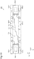
- the partitioning plate 113 connects a set of diagonal positions at both ends of the main duct 110 in the vehicle length direction 11 to be extended in the duct. As shown, in this embodiment, the partitioning plate 113 is extended in a linear shape. However, the partitioning plate 113 may be extended in any shape as long as it connects the set of diagonal positions at both ends of the duct, and, as shown in Fig. 19 , may be extended in e.g., a step shape.
- a plurality of outlets 114a are formed at appropriate intervals in the vehicle length direction 11 in each of side surfaces 110a in the vehicle length direction 11 of the main duct 110 or in each of partition walls between the main duct 110 and the chamber ducts 120.
- the outlets 114a communicate the main duct 110 with each of the chamber ducts 120.
- two discharge outlets 115 are formed in the vehicle width direction 12 in each of end surfaces 110b on the front and rear sides in the vehicle length direction 11 of the main duct 110.
- the discharge outlets 115 are connected to each of the air-conditioning apparatuses 180.
- the conditioned air generated by each of the air-conditioning apparatuses 180 is discharged through the discharge outlets 115 into the main duct 110, more specifically, into the first chamber 111 and the second chamber 112. Therefore, the conditioned air discharged from the discharge outlets 115 into the main duct 110 can flow into each of the chamber ducts 120 through the outlets 114a.
- the chamber ducts 120 arrange the first chamber duct 120-1 and the second chamber duct 120-2 on the right and left sides of the main duct 110 in the vehicle width direction 12. As described above, each of the chamber ducts 120 communicates with the main duct 110 through the outlets 114a. Each of the chamber ducts 120 thus discharges the conditioned air supplied from the main duct 110 into the interior 14 at the center portion 16 in the vehicle length direction 11. In other words, each of the chamber ducts 120 has a function for stagnating the conditioned air in the main duct 110 which flows strongly in the vehicle length direction 11 once to supply it into the interior 14.
- the chamber ducts 120 that is, the first chamber duct 120-1 and the second chamber duct 120-2, are extended along the main duct 110 in a main region 117 where end regions 116 of the main duct 110 are eliminated in the vehicle length direction 11.
- each of the chamber ducts 120 has a width which is e.g., about one-fourth the width of the main duct 110 in the vehicle width direction 12.
- each of the chamber ducts 120 has a diffuser 151 in a lower portion thereof in a vehicle height direction 13.
- the diffuser 151 is provided in the ceiling 19 of the interior, and discharges the conditioned air supplied from the main duct 110 into each of the chamber ducts 120, into the interior 14.
- the diffuser 151 has discharge outlets 153.
- the front branch ducts 130 are extended in the same line as the chamber ducts 120 in the vehicle length direction 11, and are arranged in the diagonal positions at the front and rear vehicle ends 15.
- the front branch ducts 130 discharge the conditioned air into the interior 14 at the vehicle ends 15.
- the conditioned air is discharged into the first chamber 111 and the second chamber 112 of the main duct 110 in the direction from the vehicle ends 15 to the center portion 16 by the air-conditioning apparatuses 180.
- one of the front branch ducts 130 is arranged on the upstream side of the conditioned air flowing within the first chamber 111
- the other front branch duct 130 that is, the second front branch duct 130-2
- the first front branch duct 130-1 is arranged to be adjacent to the first chamber duct 120-1
- the second front branch duct 130-2 is arranged to be adjacent to the second chamber duct 120-2.
- one front outlet 114b for each of the front branch ducts 130 is formed in each of the side surfaces 110a in each of the end regions 116 of the main duct 110 or in each of partition walls between the main duct 110 and each of the front branch ducts 130.
- Each of the front outlets 114b communicates the main duct 110 with each of the front branch ducts 130. Therefore, the front branch ducts 130 communicate with the first chamber 111 and the second chamber 112 to discharge the conditioned air into the interior 14 at the vehicle ends 15.
- the diffuser 151 is provided in the lower portion of each of the front branch ducts 130.
- each of the chamber ducts 120 and each of the front branch ducts 130 are arranged in the same line so that their center lines in the vehicle width direction 12 coincide with each other.
- each of the chamber ducts 120 and each of the front branch ducts 130 may be arranged so that their center lines are shifted from each other, and may be shifted from each other in the vehicle width direction 12.
- the front branch ducts 130 have front guide plates 131 (a first front guide plate 131-1 and a second front guide plate 131-2) .
- the front guide plates 131 intake the conditioned air which is discharged from the air-conditioning apparatuses 180 into the main duct 110, more specifically, into the first chamber 111 and the second chamber 112, into the front branch ducts 130 through the front outlets 114b.
- the first front guide plate 131-1 intakes the conditioned air which is discharged into the first chamber 111, into the first front branch duct 130-1 through the front outlet 114b
- the second front guide plate 131-2 intakes the conditioned air which is discharged into the second chamber 112, into the second front branch duct 130-2 through the front outlet 114b.
- each of the front guide plates 131 has a height which coincides with the height of the main duct 110 in the vehicle height direction 13, is provided to stand on each of the side surfaces 110a of the main duct 110, and projects from each of the front branch ducts 130 into the main duct 110. Therefore, as shown in Fig. 6 , each of the front guide plates 131 is disposed to be spaced in the vehicle length direction 11 with respect to one of the two discharge outlets 115 which discharge the conditioned air from each of the air-conditioning apparatuses 180, and is placed over the above one discharge outlet 115 at the following percentage. The area of the discharge outlet 115 is covered at a cover percentage of 35% to 60% in the vehicle width direction 12.
- Each of the front branch ducts 130 which has each of the front guide plates 131 can efficiently intake thereinto the conditioned air discharged from each of the air-conditioning apparatuses 180.
- each of the front guide plates 131 has an arc shape, but its shape is not limited to this.
- each of the front guide plates 131 may have e.g., an L-shape indicated by the solid line or a linear shape indicated by the dotted line.
- each of the front guide plates 131 may have any shape which can efficiently intake the conditioned air discharged from the discharge outlets 115 into each of the front branch ducts 130 through each of the front outlets 114b.
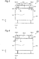
- each of the front guide plates 131 in the vehicle height direction 13 is not required to coincide with the height of the main duct 110. That is, as shown in Fig. 9 , under the condition that the cover percentage with respect to one of the discharge outlets 115 described above is satisfied, each of the front guide plates 131 can be placed to cover the entire discharge outlet 115 in the vehicle width direction 12, and to have a predetermined height from the upper surface of the main duct 110 to the lower surface thereof in the vehicle height direction 13.
- the predetermined height is a height which covers the area of one of the discharge outlets 115 at a cover percentage of 35% to 60% in the vehicle height direction 13.
- the front guide plates 131 may have the predetermined height from the lower surface of the main duct 110 to the upper surface thereof in the vehicle height direction 13.
- the respective rear branch ducts 140 are extended in the same line as the respective chamber ducts 120 in the vehicle length direction 11, and are arranged in the diagonal positions at the front and rear vehicle ends 15.
- the rear branch ducts 140 discharge the conditioned air into the interior 14 at the vehicle ends 15.
- the arrangement of the rear branch ducts 140 with respect to the conditioned air is different from the arrangement of the front branch ducts 130 with respect to the conditioned air.
- first rear branch duct 140-1 corresponding to one of the rear branch ducts 140 is arranged on the downstream side of the conditioned air flowing in the first chamber 111, not on the upstream side thereof, and the second rear branch duct 140-2 corresponding to the other rear branch duct 140 is also arranged on the downstream side of the conditioned air flowing in the second chamber 112.
- each of the chamber ducts 120 and each of the rear branch ducts 140 are arranged in the same line so that their center lines in the vehicle width direction 12 coincide with each other.
- each of the chamber ducts 120 and each of the rear branch ducts 140 may be arranged so that their center lines are shifted from each other, and may be shifted from each other in the vehicle width direction 12.
- one rear outlet 114c for each of the rear branch ducts 140 is formed in each of the side surfaces 110a in each of the end regions 116 of the main duct 110 or in each of partition walls between the main duct 110 and the rear branch ducts 140.
- Each of the rear outlets 114c communicates the main duct 110 with each of the rear branch ducts 140. Therefore, the rear branch ducts 140 communicate with the first chamber 111 and the second chamber 112 to discharge the conditioned air into the interior 14 at the vehicle ends 15.
- the diffuser 151 is provided in the lower portion of each of the rear branch ducts 140.
- each of the front branch ducts 130 described above and each of the rear branch ducts 140 described now are arranged at each of the front and rear vehicle ends 15 in the vehicle length direction 11 to sandwich each of the air-conditioning apparatuses 180 therebetween from both sides in the vehicle width direction 12.
- the first front branch duct 130-1 and the second rear branch duct 140-2 are arranged at one of the vehicle ends 15 to sandwich the first air-conditioning apparatus 180-1 therebetween, and the second front branch duct 130-2 and the first rear branch duct 140-1 are arranged at the other vehicle end 15 to sandwich the second air-conditioning apparatus 180-2 therebetween.
- the first front branch duct 130-1, the first chamber duct 120-1, and the first rear branch duct 140-1 are aligned in the vehicle length direction 11 on one side of the air-conditioning apparatuses 180 and the main duct 110 in the vehicle width direction 12, and the second rear branch duct 140-2, the second chamber duct 120-2, and the second front branch duct 130-2 are aligned on the other side thereof.
- the front branch ducts 130 and the rear branch ducts 140 arranged on both sides in the vehicle width direction 12 at the vehicle ends 15 do not discharge the conditioned air at the same amount of air from the diffusers 151 into the interior 14.
- the discharge amount of the front branch ducts 130 from the diffusers 151 into the interior 14 is higher than the discharge amount of the rear branch ducts 140 from the diffusers 151 into the interior 14. This is because, as described above, the front branch ducts 130 are located on the upstream side of the conditioned air flowing in the first chamber 111 and the second chamber 112 of the main duct 110, and have the front guide plates 131 which intake the conditioned air.
- the lower discharge volume from the rear branch ducts 140 is compensated by the discharge volume from the front branch ducts 130. This compensation can contribute to making the temperature distribution within the interior in the vehicle length direction 11 uniform.
- the first air-conditioning apparatus 180-1 and the second air-conditioning apparatus 180-2 on the front and rear sides in the vehicle length direction 11 take in the air in the interior from the suction outlets 181 thereof, regulate the air taken in to a preset temperature and then discharge the air with the preset temperature as the conditioned air through the discharge outlets 115 into the main duct 110. That is, in Fig. 1 , by way of example, the first air-conditioning apparatus 180-1 on the left side in the drawing discharges the conditioned air through the discharge outlets 115 into the first chamber 111 of the main duct 110, and the second air-conditioning apparatus 180-2 on the right side in the drawing discharges the conditioned air through the discharge outlets 115 into the second chamber 112 of the main duct 110.
- the respective chamber ducts 120 are provided corresponding to the main region 117 which is located at the center portion 16 in the vehicle length direction and occupies most part of the main duct 110, and the front branch ducts 130 and the rear branch ducts 140 are provided to communicate with the main duct 110 only in the end regions 116. Therefore, the vehicle air-conditioning duct 100 makes the discharge volume of the conditioned air into the interior 14 different and non-uniform among the respective regions of the interior. That is, the vehicle air-conditioning duct 100 can discharge the conditioned air at a higher volume of air to the center portion 16 in the vehicle length direction than to the vehicle ends 15.
- each of the chamber ducts 120 discharges the conditioned air to the center portion 16 in the vehicle length direction at an airflow volume of 105% to 120% compared to the uniform airflow volume in a state where the conditioned air is uniformly discharged into the interior 14 in the vehicle length direction 11. Further, each of the front branch ducts 130 and each of the rear branch ducts 140 discharge the conditioned air at the remaining discharge airflow volume to each of the vehicle ends 15.
- the discharge airflow volume is different between the right and left sides in the vehicle width direction 12, that is, between the front branch ducts 130 and the rear branch ducts 140.
- the front branch ducts 130 thus discharge more conditioned air into the interior 14.
- the total airflow volume of each of the front branch ducts 130 and each of the rear branch ducts 140 at each of the vehicle ends 15 is only necessary to secure 70% to 95% compared to an airflow volume in which the conditioned air is uniformly distributed according to floor area.
- the airflow volume of each of the rear branch ducts 140 is 60% compared to the airflow volume in which the conditioned air is uniformly distributed according to floor area
- the airflow volume of each of the front branch ducts 130 is only necessary to secure 80% to 130% compared to the airflow volume in which the conditioned air is uniformly distributed according to floor area.
- the conditioned air having a velocity in the vehicle length direction 11 is unbalanced at the vehicle ends due to the flow in the duct.
- the unbalance of the conditioned air to the vehicle ends 15 can be reduced.
- the temperature distribution in the interior can thus be uniform.
- the discharge airflow volume of the rear branch ducts 140 is lower at the vehicle ends 15, but the insufficient discharge airflow volume can be compensated by the discharge airflow volume of the front branch ducts 130.
- the supply airflow volume of the conditioned air to the vehicle ends 15 can thus be prevented from being insufficient.
- the non-uniform distribution configuration is a configuration having plugs which are provided at the respective regions of the interior close to the suction outlets 181 of the air-conditioning apparatuses 180 and block the discharge of the conditioned air into the interior 14 .
- Other configurations are the same as those of the first embodiment, and the descriptions of them are omitted.
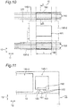
- plugs 182 are installed corresponding to each of the suction outlets 181 of each of the air-conditioning apparatuses 180 on the conditioned air discharge outlets 153 of each of the front branch ducts 130 and each of the rear branch ducts 140.
- the conditioned air When the conditioned air is discharged from each of the front branch ducts 130 and each of the rear branch ducts 140 near each of the suction outlets 181 of each of the air-conditioning apparatuses 180, the conditioned air may be taken in each of the suction outlets 181 before it is sufficiently mixed with the air in the interior. Thus, the temperature regulation in the interior 14 might not be performed appropriately. To prevent such phenomenon, the plugs 182 are installed on each of the front branch ducts 130 and each of the rear branch ducts 140.
- the conditioned air is not discharged from each of the front branch ducts 130 and each of the rear branch ducts 140 at least in sections with each of the suction outlets 181 in the vehicle length direction 11.
- the non-uniform distribution in discharging of the conditioned air is achieved.
- Each of the plugs 182 is e.g., a plate material.
- Each of the plugs 182 has, in the vehicle length direction 11, a length which is equal to or more than a length "L" of each of the suction outlets 181 of each of the air-conditioning apparatuses 180 and is equal to or less than up to ⁇ 30% (160% at the maximum) of length "L" at the front and rear part of the plug. That is, the length of each of the plugs 182 in the vehicle length direction is equal to or more than 100% of the length "L" of each of the suction outlets 181, and is equal to or less than 160% of the length "L".
- each of the plugs 182 in the vehicle width direction 12 has a size which covers two discharge outlets 153 in the vehicle width direction 12 of each of the front branch ducts 130 and each of the rear branch ducts 140.
- each of the plugs 182 is arranged to always cover the section having the length "L" of each of the suction outlets 181 in the vehicle length direction 11.
- each of the plugs 182 has a length which is more than the length "L"
- it is disposed to extend to at least one of the front and rear sides in the vehicle length direction 11 of each of the suction outlets 181.
- each of the plugs 182 is installed inside each of the front branch ducts 130 and each of the rear branch ducts 140, and closes inlet openings 152 which are communicated with the discharge outlets 153 of each of the diffusers 151.
- each of the plugs 182 is provided outside each of the front branch ducts 130 and each of the rear branch ducts 140, and closes the discharge outlets 153.
- each of the plugs 182 is provided on each of the front branch ducts 130 and each of the rear branch ducts 140.
- the conditioned air which is discharged from the outlets 153 into the interior 14 can be prevented from directly flowing into each of the suction outlets 181 of each of the air-conditioning apparatuses 180.
- the conditioned air and the air in the interior can be effectively mixed with each other, and the temperature distribution in the interior can be uniform.
- each of the plugs 182 are installed corresponding to each of the suction outlets 181 of each of the air-conditioning apparatuses 180.
- each of the plugs 182 is not limited to this configuration, and may be installed on at least one of the discharge outlets 153 of each of the front branch ducts 130 and each of the rear branch ducts 140.
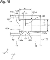
- the non-uniform distribution configuration adopts the configuration of the air-conditioning duct 100 according to the first embodiment. Further, as shown in Figs. 14 and 15 , in the non-uniform distribution configuration of the third embodiment, each of the chamber ducts 120 has therein airflow volume adjusting members 161. Other configurations are the same as those of the first embodiment, and the descriptions of them are omitted.
- each of the chamber ducts 120 has the diffuser 151 at the lower portion thereof in the vehicle height direction 13, and each of the diffusers 151 discharges the conditioned air supplied into each of the chamber ducts 120 from the main duct 110 with the conditioned air divided into a vehicle outer side 18 and a vehicle inner side 17 in the vehicle width direction 12.
- the airflow volume adjusting members 161 are installed in each of the chamber ducts 120, and strike a balance of the discharge volume of the conditioned air between the vehicle outer side 18 and the vehicle inner side 17 at the diffuser 151.
- each of the airflow volume adjusting members 161 the discharge air capacities of the conditioned air on the vehicle outer side 18 and on the vehicle inner side 17 in the diffuser 151 are balanced.
- each of the discharge airflow volume of the conditioned air from the discharge outlet 153a on the vehicle inner side 17 and the discharge airflow volume of the conditioned air from the discharge outlet 153b on the vehicle outer side 18 is preferably 50% .
- the discharge airflow volume is between 45% and 55%, the temperature distribution in the interior is not greatly unbalanced.
- Each of the airflow volume adjusting members 161 is e.g., a plate material. As shown in Fig. 15 , in the third embodiment, in the vehicle height direction 13, each of the airflow volume adjusting members 161 is extended downward from an upper surface 123 of each of the chamber ducts 120 to a position corresponding to "h" which is e.g., 50% to 65% of a height "H" of each of the chamber ducts 120.
- each of the airflow volume adjusting members 161 is arranged on the downstream side of the conditioned air in each of the chamber ducts 120, that is, on the vehicle outer side 18, so as to be spaced, by a length "g" which is e.g., 20% or less, of a width "W" of each of the chamber ducts 120, from an inlet opening 152a in each of the chamber ducts 120 communicated with the discharge outlet 153a of each of the diffusers 151 on the vehicle inner side 17.
- each of the airflow volume adjusting members 161 has a length which coincides with or substantially coincides with the length of each of the outlets 114a in each of the chamber ducts 120, and is arranged in a position corresponding to each of the outlets 114a.
- the conditioned air can be uniformly or substantially uniformly discharged from the discharge outlets 153a and 153b of each of the diffusers 151 in each of the chamber ducts 120 to the vehicle inner side 17 and the vehicle outer side 18. Therefore, the temperature distribution in the interior can be uniform.
- the non-uniform distribution configuration adopts a modification example of each of the airflow volume adjusting members 161 described in the third embodiment.
- Other configurations are the same as those of the first embodiment, and the descriptions of them are omitted.
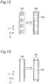
- each of closing plates 162 ( Fig. 7 ) or each of porous plates 163 ( Fig. 18 ) as the airflow volume adjusting member 161 is arranged on an inlet opening 152b which is communicated with the discharge outlet 153b on the vehicle outer side 18 of each of the diffusers 151 in each of the chamber ducts 120.
- Each of the closing plates 162 or each of the porous plates 163 is provided on the inlet opening 152b corresponding to the vehicle outer side 18.
- an open ratio of the inlet opening 152b is adjusted to balance the discharge airflow volume of the conditioned air on the vehicle inner side 17 with the discharge airflow volume of the conditioned air on the vehicle outer side 18 in the diffuser 151.
- each of the closing plates 162 is e.g., a plate material, and closes part of the inlet opening 152b in the vehicle length direction 11.
- the closing plates 162 are provided at both ends of the inlet opening 152b, however the installed position thereof is not limited to this.
- each of the inlet openings 152a and 152b is formed to be continuous in the vehicle length direction 11 in each of the chamber ducts 120.
- a plurality of inlet openings 152a and 152b may be formed at predetermined intervals in the vehicle length direction 11.
- the porous plate 163 shown in Fig. 18 shows an example, which does not limit the arrangement and alignment of the hole.
- each of the closing plates 162 and each of the porous plates 163 are arranged on the inlet opening 152b in each of the chamber ducts 120.
- each of the closing plates 162 and each of the porous plates 163 may be arranged outside each of the chamber ducts 120 and on the discharge outlet 153b on the vehicle outer side 18 of the diffuser 151.
- the discharge volume of the conditioned air on the vehicle inner side 17 in each of the chamber ducts 120 and the discharge volume of the conditioned air on the vehicle outer side 18 in each of the chamber ducts 120 at each of the diffusers 151 can be adjusted to be balanced. Therefore, the temperature distribution in the interior can be uniform.
- the air-conditioning apparatuses 180 are installed at the vehicle ends 15 in the vehicle length direction 11. However, like a vehicle air-conditioning system 201 shown in Fig. 20 , for instance, one air-conditioning apparatus 180 may be arranged at the center portion 16 in the vehicle length direction.
- the present invention is applicable to the vehicle air-conditioning duct in a large-sized passenger car, such as a railcar, an aircraft, a ship, and a bus, and the vehicle air-conditioning system including the vehicle air-conditioning duct.
Landscapes
- Engineering & Computer Science (AREA)
- Mechanical Engineering (AREA)
- Physics & Mathematics (AREA)
- Thermal Sciences (AREA)
- Chemical & Material Sciences (AREA)
- Combustion & Propulsion (AREA)
- General Engineering & Computer Science (AREA)
- Life Sciences & Earth Sciences (AREA)
- Wood Science & Technology (AREA)
- Air-Conditioning For Vehicles (AREA)
- Air-Flow Control Members (AREA)
- Duct Arrangements (AREA)
Applications Claiming Priority (2)
| Application Number | Priority Date | Filing Date | Title |
|---|---|---|---|
| JP2012013066A JP6012970B2 (ja) | 2012-01-25 | 2012-01-25 | 車両空調ダクト及び鉄道車両 |
| PCT/JP2012/078857 WO2013111417A1 (ja) | 2012-01-25 | 2012-11-07 | 車両空調ダクト及び鉄道車両 |
Publications (3)
| Publication Number | Publication Date |
|---|---|
| EP2810846A1 EP2810846A1 (en) | 2014-12-10 |
| EP2810846A4 EP2810846A4 (en) | 2015-12-09 |
| EP2810846B1 true EP2810846B1 (en) | 2019-07-10 |
Family
ID=48873159
Family Applications (1)
| Application Number | Title | Priority Date | Filing Date |
|---|---|---|---|
| EP12866750.8A Active EP2810846B1 (en) | 2012-01-25 | 2012-11-07 | Air-conditioning duct in passenger car and railcar |
Country Status (5)
| Country | Link |
|---|---|
| US (1) | US9771086B2 (https=) |
| EP (1) | EP2810846B1 (https=) |
| JP (1) | JP6012970B2 (https=) |
| CN (1) | CN104066640B (https=) |
| WO (1) | WO2013111417A1 (https=) |
Families Citing this family (15)
| Publication number | Priority date | Publication date | Assignee | Title |
|---|---|---|---|---|
| EP3418088B1 (en) * | 2013-10-18 | 2020-09-09 | Hitachi, Ltd. | Moving vehicle |
| JP6151656B2 (ja) * | 2014-03-18 | 2017-06-21 | Jr東日本テクノロジー株式会社 | 鉄道車両の設計方法、鉄道車両の製造方法及び鉄道車両 |
| JP6395431B2 (ja) * | 2014-04-30 | 2018-09-26 | 三菱電機株式会社 | 車両用空気調和装置 |
| FR3029485B1 (fr) * | 2014-12-03 | 2018-03-16 | Alstom Transport Technologies | Dispositif aeraulique de refroidissement d'un element d'un vehicule ferroviaire et vehicule ferroviaire correspondant |
| FR3041289B1 (fr) * | 2015-09-22 | 2017-10-20 | Alstom Transp Tech | Dispositif perfectionne de climatisation, notamment pour une salle de vehicule ferroviaire |
| JP6694329B2 (ja) * | 2016-06-03 | 2020-05-13 | 川崎重工業株式会社 | 鉄道車両用空調ダクト |
| JP6845622B2 (ja) * | 2016-06-03 | 2021-03-17 | 川崎重工業株式会社 | 車両用空調ダクト及び鉄道車両 |
| JP6713856B2 (ja) * | 2016-07-01 | 2020-06-24 | 東日本旅客鉄道株式会社 | ダクト構成部材および鉄道車両 |
| JP6361076B1 (ja) * | 2017-08-31 | 2018-07-25 | 三菱重工エンジニアリング株式会社 | 車両用空調機の室内機、これを備える車両、天井板組立体、室内機のメンテナンス方法、及び天井板の交換方法 |
| CN108482072B (zh) * | 2018-03-08 | 2020-09-29 | 潍柴动力股份有限公司 | 一种平台化风道 |
| CN109017198A (zh) * | 2018-06-21 | 2018-12-18 | 南京理工大学 | 一种汽车空调均匀送风道 |
| CN109017846A (zh) * | 2018-07-27 | 2018-12-18 | 中车浦镇庞巴迪运输系统有限公司 | 一种用于轨道车辆空调系统用变截面风道结构 |
| WO2020044536A1 (ja) * | 2018-08-31 | 2020-03-05 | 川崎重工業株式会社 | 鉄道車両用空調ダクト |
| CA3120220A1 (en) * | 2018-12-21 | 2020-06-25 | Mhi Rj Aviation Ulc | Air deflector and system including the air deflector |
| CN113022615B (zh) * | 2021-02-08 | 2022-05-13 | 中车株洲电力机车有限公司 | 轨道交通车辆及其空调送风均匀性自适应调节方法与系统 |
Family Cites Families (32)
| Publication number | Priority date | Publication date | Assignee | Title |
|---|---|---|---|---|
| US2673512A (en) * | 1948-09-17 | 1954-03-30 | Gen Motors Corp | Air conditioning apparatus |
| US2698569A (en) * | 1951-08-10 | 1955-01-04 | Budd Co | Air conditioning means for vehicles |
| DE2308839B2 (de) * | 1972-03-07 | 1976-07-01 | Alex. Friedmann Kg, Wien | Einkanal-klimaanlage fuer schienenfahrzeuge |
| JPS5339927Y2 (https=) * | 1976-05-28 | 1978-09-27 | ||
| JPS54169305U (https=) * | 1978-05-19 | 1979-11-29 | ||
| JPS5579952A (en) * | 1978-12-14 | 1980-06-16 | Hitachi Ltd | Cold air discharge grill in air-conditioning duct in vehicle |
| DE2909628C2 (de) * | 1979-03-12 | 1984-11-15 | Hagenuk GmbH, 2300 Kiel | Vorrichtung zur Regelung des KATA-Wertes |
| JPS55131864U (https=) * | 1979-03-14 | 1980-09-18 | ||
| JPS55131864A (en) | 1979-03-30 | 1980-10-14 | Nec Corp | Hysteresis information storage unit of logic unit |
| JPS5875009U (ja) * | 1981-11-13 | 1983-05-20 | 株式会社日立製作所 | 車両の空調装置 |
| JPS59128405A (ja) * | 1983-01-13 | 1984-07-24 | Yokogawa Hokushin Electric Corp | 水晶歪ゲ−ジ |
| JPS59128405U (ja) * | 1983-02-10 | 1984-08-29 | 株式会社東芝 | 車両用空気調和機 |
| JPS6045211U (ja) * | 1983-09-05 | 1985-03-30 | 三菱電機株式会社 | 車両用空気調和装置 |
| JPS6045419A (ja) * | 1984-07-20 | 1985-03-11 | Hitachi Ltd | 車両の空調装置 |
| JPS62137216A (ja) * | 1985-12-11 | 1987-06-20 | Hitachi Ltd | 鉄道車両用空調ダクト |
| US4888959A (en) | 1989-02-09 | 1989-12-26 | Thermo King Corporation | Bus air conditioner suitable for mounting within the normal profile of a bus |
| JPH0645211A (ja) * | 1992-07-24 | 1994-02-18 | Fuji Electric Co Ltd | 半導体製造装置 |
| EP0716014B1 (de) * | 1994-12-06 | 1998-04-29 | Drägerwerk Aktiengesellschaft | Abdeckplatte mit Längenausgleich |
| JP4224939B2 (ja) * | 2000-03-31 | 2009-02-18 | 株式会社デンソー | 車両用空調装置 |
| JP2002337540A (ja) * | 2001-05-15 | 2002-11-27 | Mitsubishi Motors Corp | 空調騒音の低減構造 |
| JP4943245B2 (ja) | 2007-06-28 | 2012-05-30 | 株式会社ハウステック | 鉄道車両用の天井ユニット |
| JP5049746B2 (ja) * | 2007-11-07 | 2012-10-17 | 日本車輌製造株式会社 | 鉄道車両 |
| AU2009230735B1 (en) * | 2009-01-08 | 2010-01-21 | Shane Ramodien | Electronic equipment housing |
| JP5324973B2 (ja) | 2009-03-25 | 2013-10-23 | 三菱重工業株式会社 | 軌道系車両の空調装置 |
| JP2011156974A (ja) | 2010-02-01 | 2011-08-18 | Toyota Motor Corp | 車両用空調ダクト構造 |
| JP2011162085A (ja) * | 2010-02-10 | 2011-08-25 | Mitsubishi Heavy Ind Ltd | 空調システム及び空調システムを搭載する車両 |
| CN201646726U (zh) * | 2010-03-12 | 2010-11-24 | 南车青岛四方机车车辆股份有限公司 | 高速铁路车辆换气装置 |
| JP5603153B2 (ja) * | 2010-06-28 | 2014-10-08 | 川崎重工業株式会社 | 鉄道車両の空調システム |
| US20120129443A1 (en) * | 2010-10-06 | 2012-05-24 | Philip Bastow | Airflow and Heating Control Supply Air Terminal |
| CN202038315U (zh) * | 2011-03-31 | 2011-11-16 | 青岛理工大学 | 一种高速列车用外接式变截面均匀送风系统 |
| JP6045211B2 (ja) * | 2012-06-15 | 2016-12-14 | 日野自動車株式会社 | サスペンション制御装置及び車両 |
| EP3089320A4 (en) * | 2013-12-10 | 2016-12-28 | Chugoku Electric Power | POWER TRANSMISSION DEVICE AND POWER SUPPLY SYSTEM |
-
2012
- 2012-01-25 JP JP2012013066A patent/JP6012970B2/ja active Active
- 2012-11-07 CN CN201280068029.2A patent/CN104066640B/zh active Active
- 2012-11-07 WO PCT/JP2012/078857 patent/WO2013111417A1/ja not_active Ceased
- 2012-11-07 US US14/369,907 patent/US9771086B2/en active Active
- 2012-11-07 EP EP12866750.8A patent/EP2810846B1/en active Active
Non-Patent Citations (1)
| Title |
|---|
| None * |
Also Published As
| Publication number | Publication date |
|---|---|
| US20140370796A1 (en) | 2014-12-18 |
| CN104066640A (zh) | 2014-09-24 |
| WO2013111417A1 (ja) | 2013-08-01 |
| JP6012970B2 (ja) | 2016-10-25 |
| JP2013151224A (ja) | 2013-08-08 |
| US9771086B2 (en) | 2017-09-26 |
| EP2810846A4 (en) | 2015-12-09 |
| EP2810846A1 (en) | 2014-12-10 |
| CN104066640B (zh) | 2016-10-12 |
Similar Documents
| Publication | Publication Date | Title |
|---|---|---|
| EP2810846B1 (en) | Air-conditioning duct in passenger car and railcar | |
| US8789766B2 (en) | Mixing device for aircraft air conditioning system | |
| EP3059105A1 (en) | Moving vehicle | |
| US8608532B2 (en) | Climate control duct architecture for a vehicle | |
| JP6694329B2 (ja) | 鉄道車両用空調ダクト | |
| EP3728036B1 (en) | Overhead flow distribution assembly for aircraft cabin | |
| US7462099B2 (en) | Air-guiding system for a ventilation system of a vehicle | |
| US7575511B2 (en) | Temperature door for a vehicle and heating, ventilation, and air conditioning system | |
| KR20170101854A (ko) | 자동차 공조 시스템용 공기 분배 어셈블리 | |
| US6296563B1 (en) | Device for the distribution of ventilation air in the passenger compartment of a motor vehicle | |
| US20200269986A1 (en) | Air conditioning piping structure for aircraft and air conditioning system | |
| JP5759108B2 (ja) | 自動車の車室の換気、暖房、および/または空調装置 | |
| JP2006010220A (ja) | 空調装置 | |
| US12358341B2 (en) | Air-conditioning device for vehicle | |
| JP2013103573A (ja) | 空調設備及び車両 | |
| KR102379897B1 (ko) | 차량용 모듈식 공기 조화 시스템 | |
| WO2020045624A1 (ja) | 鉄道車両用空調ダクト | |
| US20250262915A1 (en) | System for Supplying an Air Flow to an Air Diffuser and Air Diffuser System for a Vehicle | |
| KR102336365B1 (ko) | 자동차용 공기 조화 장치 | |
| CN120828648A (zh) | 矢量排气装置和机动车 | |
| US20090321042A1 (en) | Vehicular air conditioning unit | |
| HK40034429A (en) | Overhead flow distribution assembly for aircraft cabin | |
| JP2010167993A (ja) | 車両用空調装置 |
Legal Events
| Date | Code | Title | Description |
|---|---|---|---|
| PUAI | Public reference made under article 153(3) epc to a published international application that has entered the european phase |
Free format text: ORIGINAL CODE: 0009012 |
|
| 17P | Request for examination filed |
Effective date: 20140724 |
|
| AK | Designated contracting states |
Kind code of ref document: A1 Designated state(s): AL AT BE BG CH CY CZ DE DK EE ES FI FR GB GR HR HU IE IS IT LI LT LU LV MC MK MT NL NO PL PT RO RS SE SI SK SM TR |
|
| AX | Request for extension of the european patent |
Extension state: BA ME |
|
| RIN1 | Information on inventor provided before grant (corrected) |
Inventor name: SAKAGAWA, KEIJI Inventor name: ONITAKE, YASUO Inventor name: HARA, YOSHINORI Inventor name: SASAKI, TAKASHI Inventor name: KONDO, KOUKI Inventor name: MITANI, RYOSUKE |
|
| DAX | Request for extension of the european patent (deleted) | ||
| RA4 | Supplementary search report drawn up and despatched (corrected) |
Effective date: 20151109 |
|
| RIC1 | Information provided on ipc code assigned before grant |
Ipc: B61D 17/12 20060101ALI20151103BHEP Ipc: B61D 27/00 20060101AFI20151103BHEP Ipc: B60H 1/00 20060101ALI20151103BHEP Ipc: F24F 7/10 20060101ALI20151103BHEP |
|
| GRAP | Despatch of communication of intention to grant a patent |
Free format text: ORIGINAL CODE: EPIDOSNIGR1 |
|
| STAA | Information on the status of an ep patent application or granted ep patent |
Free format text: STATUS: GRANT OF PATENT IS INTENDED |
|
| RIC1 | Information provided on ipc code assigned before grant |
Ipc: B60H 1/00 20060101ALI20190123BHEP Ipc: F24F 7/04 20060101ALI20190123BHEP Ipc: B61D 17/12 20060101ALI20190123BHEP Ipc: F24F 13/02 20060101ALI20190123BHEP Ipc: B61D 27/00 20060101AFI20190123BHEP |
|
| INTG | Intention to grant announced |
Effective date: 20190214 |
|
| GRAS | Grant fee paid |
Free format text: ORIGINAL CODE: EPIDOSNIGR3 |
|
| GRAA | (expected) grant |
Free format text: ORIGINAL CODE: 0009210 |
|
| STAA | Information on the status of an ep patent application or granted ep patent |
Free format text: STATUS: THE PATENT HAS BEEN GRANTED |
|
| AK | Designated contracting states |
Kind code of ref document: B1 Designated state(s): AL AT BE BG CH CY CZ DE DK EE ES FI FR GB GR HR HU IE IS IT LI LT LU LV MC MK MT NL NO PL PT RO RS SE SI SK SM TR |
|
| REG | Reference to a national code |
Ref country code: GB Ref legal event code: FG4D |
|
| REG | Reference to a national code |
Ref country code: CH Ref legal event code: EP Ref country code: AT Ref legal event code: REF Ref document number: 1153267 Country of ref document: AT Kind code of ref document: T Effective date: 20190715 |
|
| REG | Reference to a national code |
Ref country code: DE Ref legal event code: R096 Ref document number: 602012061987 Country of ref document: DE |
|
| REG | Reference to a national code |
Ref country code: IE Ref legal event code: FG4D |
|
| REG | Reference to a national code |
Ref country code: NL Ref legal event code: MP Effective date: 20190710 |
|
| REG | Reference to a national code |
Ref country code: LT Ref legal event code: MG4D |
|
| REG | Reference to a national code |
Ref country code: AT Ref legal event code: MK05 Ref document number: 1153267 Country of ref document: AT Kind code of ref document: T Effective date: 20190710 |
|
| PG25 | Lapsed in a contracting state [announced via postgrant information from national office to epo] |
Ref country code: HR Free format text: LAPSE BECAUSE OF FAILURE TO SUBMIT A TRANSLATION OF THE DESCRIPTION OR TO PAY THE FEE WITHIN THE PRESCRIBED TIME-LIMIT Effective date: 20190710 Ref country code: LT Free format text: LAPSE BECAUSE OF FAILURE TO SUBMIT A TRANSLATION OF THE DESCRIPTION OR TO PAY THE FEE WITHIN THE PRESCRIBED TIME-LIMIT Effective date: 20190710 Ref country code: AT Free format text: LAPSE BECAUSE OF FAILURE TO SUBMIT A TRANSLATION OF THE DESCRIPTION OR TO PAY THE FEE WITHIN THE PRESCRIBED TIME-LIMIT Effective date: 20190710 Ref country code: NO Free format text: LAPSE BECAUSE OF FAILURE TO SUBMIT A TRANSLATION OF THE DESCRIPTION OR TO PAY THE FEE WITHIN THE PRESCRIBED TIME-LIMIT Effective date: 20191010 Ref country code: FI Free format text: LAPSE BECAUSE OF FAILURE TO SUBMIT A TRANSLATION OF THE DESCRIPTION OR TO PAY THE FEE WITHIN THE PRESCRIBED TIME-LIMIT Effective date: 20190710 Ref country code: SE Free format text: LAPSE BECAUSE OF FAILURE TO SUBMIT A TRANSLATION OF THE DESCRIPTION OR TO PAY THE FEE WITHIN THE PRESCRIBED TIME-LIMIT Effective date: 20190710 Ref country code: NL Free format text: LAPSE BECAUSE OF FAILURE TO SUBMIT A TRANSLATION OF THE DESCRIPTION OR TO PAY THE FEE WITHIN THE PRESCRIBED TIME-LIMIT Effective date: 20190710 Ref country code: PT Free format text: LAPSE BECAUSE OF FAILURE TO SUBMIT A TRANSLATION OF THE DESCRIPTION OR TO PAY THE FEE WITHIN THE PRESCRIBED TIME-LIMIT Effective date: 20191111 Ref country code: BG Free format text: LAPSE BECAUSE OF FAILURE TO SUBMIT A TRANSLATION OF THE DESCRIPTION OR TO PAY THE FEE WITHIN THE PRESCRIBED TIME-LIMIT Effective date: 20191010 |
|
| PG25 | Lapsed in a contracting state [announced via postgrant information from national office to epo] |
Ref country code: RS Free format text: LAPSE BECAUSE OF FAILURE TO SUBMIT A TRANSLATION OF THE DESCRIPTION OR TO PAY THE FEE WITHIN THE PRESCRIBED TIME-LIMIT Effective date: 20190710 Ref country code: IS Free format text: LAPSE BECAUSE OF FAILURE TO SUBMIT A TRANSLATION OF THE DESCRIPTION OR TO PAY THE FEE WITHIN THE PRESCRIBED TIME-LIMIT Effective date: 20191110 Ref country code: ES Free format text: LAPSE BECAUSE OF FAILURE TO SUBMIT A TRANSLATION OF THE DESCRIPTION OR TO PAY THE FEE WITHIN THE PRESCRIBED TIME-LIMIT Effective date: 20190710 Ref country code: LV Free format text: LAPSE BECAUSE OF FAILURE TO SUBMIT A TRANSLATION OF THE DESCRIPTION OR TO PAY THE FEE WITHIN THE PRESCRIBED TIME-LIMIT Effective date: 20190710 Ref country code: AL Free format text: LAPSE BECAUSE OF FAILURE TO SUBMIT A TRANSLATION OF THE DESCRIPTION OR TO PAY THE FEE WITHIN THE PRESCRIBED TIME-LIMIT Effective date: 20190710 Ref country code: GR Free format text: LAPSE BECAUSE OF FAILURE TO SUBMIT A TRANSLATION OF THE DESCRIPTION OR TO PAY THE FEE WITHIN THE PRESCRIBED TIME-LIMIT Effective date: 20191011 |
|
| PG25 | Lapsed in a contracting state [announced via postgrant information from national office to epo] |
Ref country code: TR Free format text: LAPSE BECAUSE OF FAILURE TO SUBMIT A TRANSLATION OF THE DESCRIPTION OR TO PAY THE FEE WITHIN THE PRESCRIBED TIME-LIMIT Effective date: 20190710 |
|
| PG25 | Lapsed in a contracting state [announced via postgrant information from national office to epo] |
Ref country code: PL Free format text: LAPSE BECAUSE OF FAILURE TO SUBMIT A TRANSLATION OF THE DESCRIPTION OR TO PAY THE FEE WITHIN THE PRESCRIBED TIME-LIMIT Effective date: 20190710 Ref country code: IT Free format text: LAPSE BECAUSE OF FAILURE TO SUBMIT A TRANSLATION OF THE DESCRIPTION OR TO PAY THE FEE WITHIN THE PRESCRIBED TIME-LIMIT Effective date: 20190710 Ref country code: RO Free format text: LAPSE BECAUSE OF FAILURE TO SUBMIT A TRANSLATION OF THE DESCRIPTION OR TO PAY THE FEE WITHIN THE PRESCRIBED TIME-LIMIT Effective date: 20190710 Ref country code: EE Free format text: LAPSE BECAUSE OF FAILURE TO SUBMIT A TRANSLATION OF THE DESCRIPTION OR TO PAY THE FEE WITHIN THE PRESCRIBED TIME-LIMIT Effective date: 20190710 Ref country code: DK Free format text: LAPSE BECAUSE OF FAILURE TO SUBMIT A TRANSLATION OF THE DESCRIPTION OR TO PAY THE FEE WITHIN THE PRESCRIBED TIME-LIMIT Effective date: 20190710 |
|
| PG25 | Lapsed in a contracting state [announced via postgrant information from national office to epo] |
Ref country code: IS Free format text: LAPSE BECAUSE OF FAILURE TO SUBMIT A TRANSLATION OF THE DESCRIPTION OR TO PAY THE FEE WITHIN THE PRESCRIBED TIME-LIMIT Effective date: 20200224 Ref country code: SM Free format text: LAPSE BECAUSE OF FAILURE TO SUBMIT A TRANSLATION OF THE DESCRIPTION OR TO PAY THE FEE WITHIN THE PRESCRIBED TIME-LIMIT Effective date: 20190710 Ref country code: CZ Free format text: LAPSE BECAUSE OF FAILURE TO SUBMIT A TRANSLATION OF THE DESCRIPTION OR TO PAY THE FEE WITHIN THE PRESCRIBED TIME-LIMIT Effective date: 20190710 Ref country code: SK Free format text: LAPSE BECAUSE OF FAILURE TO SUBMIT A TRANSLATION OF THE DESCRIPTION OR TO PAY THE FEE WITHIN THE PRESCRIBED TIME-LIMIT Effective date: 20190710 |
|
| REG | Reference to a national code |
Ref country code: DE Ref legal event code: R097 Ref document number: 602012061987 Country of ref document: DE |
|
| REG | Reference to a national code |
Ref country code: CH Ref legal event code: PL |
|
| PLBE | No opposition filed within time limit |
Free format text: ORIGINAL CODE: 0009261 |
|
| STAA | Information on the status of an ep patent application or granted ep patent |
Free format text: STATUS: NO OPPOSITION FILED WITHIN TIME LIMIT |
|
| PG2D | Information on lapse in contracting state deleted |
Ref country code: IS |
|
| PG25 | Lapsed in a contracting state [announced via postgrant information from national office to epo] |
Ref country code: CH Free format text: LAPSE BECAUSE OF NON-PAYMENT OF DUE FEES Effective date: 20191130 Ref country code: LI Free format text: LAPSE BECAUSE OF NON-PAYMENT OF DUE FEES Effective date: 20191130 Ref country code: LU Free format text: LAPSE BECAUSE OF NON-PAYMENT OF DUE FEES Effective date: 20191107 Ref country code: MC Free format text: LAPSE BECAUSE OF FAILURE TO SUBMIT A TRANSLATION OF THE DESCRIPTION OR TO PAY THE FEE WITHIN THE PRESCRIBED TIME-LIMIT Effective date: 20190710 |
|
| 26N | No opposition filed |
Effective date: 20200603 |
|
| REG | Reference to a national code |
Ref country code: BE Ref legal event code: MM Effective date: 20191130 |
|
| PG25 | Lapsed in a contracting state [announced via postgrant information from national office to epo] |
Ref country code: SI Free format text: LAPSE BECAUSE OF FAILURE TO SUBMIT A TRANSLATION OF THE DESCRIPTION OR TO PAY THE FEE WITHIN THE PRESCRIBED TIME-LIMIT Effective date: 20190710 |
|
| GBPC | Gb: european patent ceased through non-payment of renewal fee |
Effective date: 20191107 |
|
| PG25 | Lapsed in a contracting state [announced via postgrant information from national office to epo] |
Ref country code: GB Free format text: LAPSE BECAUSE OF NON-PAYMENT OF DUE FEES Effective date: 20191107 Ref country code: IE Free format text: LAPSE BECAUSE OF NON-PAYMENT OF DUE FEES Effective date: 20191107 |
|
| PG25 | Lapsed in a contracting state [announced via postgrant information from national office to epo] |
Ref country code: BE Free format text: LAPSE BECAUSE OF NON-PAYMENT OF DUE FEES Effective date: 20191130 |
|
| PG25 | Lapsed in a contracting state [announced via postgrant information from national office to epo] |
Ref country code: CY Free format text: LAPSE BECAUSE OF FAILURE TO SUBMIT A TRANSLATION OF THE DESCRIPTION OR TO PAY THE FEE WITHIN THE PRESCRIBED TIME-LIMIT Effective date: 20190710 |
|
| PG25 | Lapsed in a contracting state [announced via postgrant information from national office to epo] |
Ref country code: MT Free format text: LAPSE BECAUSE OF FAILURE TO SUBMIT A TRANSLATION OF THE DESCRIPTION OR TO PAY THE FEE WITHIN THE PRESCRIBED TIME-LIMIT Effective date: 20190710 Ref country code: HU Free format text: LAPSE BECAUSE OF FAILURE TO SUBMIT A TRANSLATION OF THE DESCRIPTION OR TO PAY THE FEE WITHIN THE PRESCRIBED TIME-LIMIT; INVALID AB INITIO Effective date: 20121107 |
|
| REG | Reference to a national code |
Ref country code: DE Ref legal event code: R081 Ref document number: 602012061987 Country of ref document: DE Owner name: KAWASAKI RAILCAR MANUFACTURING CO., LTD., KOBE, JP Free format text: FORMER OWNER: KAWASAKI JUKOGYO KABUSHIKI KAISHA, KOBE-SHI, HYOGO, JP |
|
| PG25 | Lapsed in a contracting state [announced via postgrant information from national office to epo] |
Ref country code: MK Free format text: LAPSE BECAUSE OF FAILURE TO SUBMIT A TRANSLATION OF THE DESCRIPTION OR TO PAY THE FEE WITHIN THE PRESCRIBED TIME-LIMIT Effective date: 20190710 |
|
| PGFP | Annual fee paid to national office [announced via postgrant information from national office to epo] |
Ref country code: DE Payment date: 20241001 Year of fee payment: 13 |
|
| PGFP | Annual fee paid to national office [announced via postgrant information from national office to epo] |
Ref country code: FR Payment date: 20241001 Year of fee payment: 13 |