EP2810567B9 - Juice-extraction module for juicing apparatus - Google Patents
Juice-extraction module for juicing apparatus Download PDFInfo
- Publication number
- EP2810567B9 EP2810567B9 EP13854209.7A EP13854209A EP2810567B9 EP 2810567 B9 EP2810567 B9 EP 2810567B9 EP 13854209 A EP13854209 A EP 13854209A EP 2810567 B9 EP2810567 B9 EP 2810567B9
- Authority
- EP
- European Patent Office
- Prior art keywords
- crushing
- input
- extraction module
- cover
- juice extraction
- Prior art date
- Legal status (The legal status is an assumption and is not a legal conclusion. Google has not performed a legal analysis and makes no representation as to the accuracy of the status listed.)
- Active
Links
- 238000000605 extraction Methods 0.000 title claims description 58
- 239000000463 material Substances 0.000 claims description 104
- 235000011389 fruit/vegetable juice Nutrition 0.000 claims description 77
- 230000000149 penetrating effect Effects 0.000 claims description 3
- 238000000034 method Methods 0.000 description 3
- 238000003801 milling Methods 0.000 description 3
- 238000000465 moulding Methods 0.000 description 3
- 230000007423 decrease Effects 0.000 description 2
- 230000000694 effects Effects 0.000 description 2
- 238000003780 insertion Methods 0.000 description 2
- 230000037431 insertion Effects 0.000 description 2
- 239000000356 contaminant Substances 0.000 description 1
- 238000011109 contamination Methods 0.000 description 1
- 239000000428 dust Substances 0.000 description 1
Images


Classifications
-
- A—HUMAN NECESSITIES
- A23—FOODS OR FOODSTUFFS; TREATMENT THEREOF, NOT COVERED BY OTHER CLASSES
- A23N—MACHINES OR APPARATUS FOR TREATING HARVESTED FRUIT, VEGETABLES OR FLOWER BULBS IN BULK, NOT OTHERWISE PROVIDED FOR; PEELING VEGETABLES OR FRUIT IN BULK; APPARATUS FOR PREPARING ANIMAL FEEDING- STUFFS
- A23N1/00—Machines or apparatus for extracting juice
- A23N1/02—Machines or apparatus for extracting juice combined with disintegrating or cutting
-
- A—HUMAN NECESSITIES
- A47—FURNITURE; DOMESTIC ARTICLES OR APPLIANCES; COFFEE MILLS; SPICE MILLS; SUCTION CLEANERS IN GENERAL
- A47J—KITCHEN EQUIPMENT; COFFEE MILLS; SPICE MILLS; APPARATUS FOR MAKING BEVERAGES
- A47J19/00—Household machines for straining foodstuffs; Household implements for mashing or straining foodstuffs
- A47J19/02—Citrus fruit squeezers; Other fruit juice extracting devices
- A47J19/025—Citrus fruit squeezers; Other fruit juice extracting devices including a pressing screw
Definitions
- the present invention relates to a juice extraction module for a juicer, and more specifically, to a juice extraction module for a juicer having an improved structure capable of eliminating the inconvenience that a material should be chopped before the material is input into the juicer.
- a juicer in general, includes a main body, and a juice extraction module mounted onto the main body.
- the juice extraction module includes a container having a juice extraction space, a lid having an input portion through which a material is input into the container, a screw for extracting juice from the material in the container, and a sieve for separating juice and residues from each other.
- the main body includes a driving motor for rotating the screw, and a shaft of the driving motor is connected to the screw in the juice extraction module.
- the material should be chopped into such a size that the screw can extract juice.
- Korean Patent No. 10-0793852 discloses a juicer configured to cut or sever a material by a screw blade protruding from a central axis of a screw toward one side of an uppermost end.
- the material when a material has a size larger than the length of the screw blade, the material should be chopped in advance into a size smaller than the length of the screw blade.
- Korean Patent No. 10-0966607 discloses a juicer having a grater provided in an entire upper surface over a screw to crush a material just before juice is extracted.
- the conventional juicer cuts the material and then mills the cut pieces of the material while they are pressed against a sieve in a juice extraction process, the sieve may be deformed in a moment by the pressed cut pieces.
- Such deformation destroys a molding for holding a shape of the sieve or decreases the bond between the molding and the sieve to generate a gap between the molding and the sieve causing a leakage of residues and a decrease in juice extraction efficiency.
- an object of the present invention is to provide a juice extraction module for a juicer, in which a structure of crushing a material in advance is provided in a lid and a screw to make it possible to eliminate an inconvenient procedure of chopping or cutting a material in advance before inputting the material through an input portion.
- another object of the present invention is to provide a juice extraction module for a juicer, which has an enlarged input portion for allowing a large material to be input therethrough and at the same time can prevent a safety hazard incident to the size of the enlarged input portion.
- a juice extraction module for a juicer which includes a container formed with a juice discharge port; a sieve positioned inside of the container; a screw positioned inside of the sieve to extract juice from a material; a lid coupled to a top end of the container and formed with an input portion through which the material is input; and a safety cover rotatably installed to a main input opening of a top end of the input portion to be movable between a first position and a second position, wherein the safety cover comprises a first cover portion erected to open the main input opening in the first position and closing the main input opening in the second position; and a second cover portion formed integrally with the first cover portion, the second cover portion moving the safety cover to the second position when the second cover portion is pushed by a downward applied force from the first position, whereby the first cover portion blocks the main input opening.
- the safety cover is connected by a hinge to both sides of the main input opening at both sides of a position in which the first cover portion and the second cover portion cross each other.
- the juice extraction module further includes a bias means installed to the hinge so that the safety cover is biased to the first position.
- the bias means includes a torsion spring or weight.
- the juice extraction module further comprising a locking unit for locking the safety cover at the second position, wherein the locking unit comprises a knob positioned on an upper surface of the first cover portion and a locking piece positioned on a lower surface of the first cover portion and connected to the knob by an connection portion penetrating the first cover portion, the locking unit having a locking groove formed in the inner surface of the input portion so that the locking piece rotated by the knob is inserted into the locking groove.
- the locking unit comprises a knob positioned on an upper surface of the first cover portion and a locking piece positioned on a lower surface of the first cover portion and connected to the knob by an connection portion penetrating the first cover portion, the locking unit having a locking groove formed in the inner surface of the input portion so that the locking piece rotated by the knob is inserted into the locking groove.
- the input portion further comprises a secondary input opening formed in the top end thereof, the secondary input opening having a size smaller than the main input opening.
- the safety cover has a third position to which the safety cover is further rotated after passing the second position, and the first cover portion and the second cover portion at least partially cover the main input opening and the secondary input opening in the third position, respectively.
- the juice extraction module further includes a crushing portion formed on a top end of the screw to be narrowed upward, the crushing portion having a crushing blade formed thereon; and a crushing processing portion connected to the input portion and formed in a bottom of the lid to be concave for accommodating the crushing portion, wherein the crushing blade crushes the material in advance within the crushing processing portion.
- the crushing blade is formed so that the material input through the input portion is crushed while a lateral side of the material is pushed outwards, and the crushing processing portion is provided with an inner surface to hold the material pushed outwards by the crushing blade, whereby the material is crushed between the crushing blade and the inner surface of the crushing processing portion.
- the crushing processing portion covers an entire bottom region of the input portion at the height of the crushing processing portion connected to a bottom end of the input portion.
- a bottom region of the input portion is positioned to be offset within a semicircle region of a circle having a diameter corresponding to a diameter of the crushing processing portion with a central shaft of the screw as a center.
- the inner surface of the crushing processing portion comprises a material guide surface continuing from the input portion and formed to be inclined toward a central axis of the crushing portion, whereby the material guide surface guides the material so that a lateral side of the material begins to be milled by the crushing blade, wherein a bottom end of the material guide surface conforms to an inner surface of the sieve.
- the inner surface of the crushing processing portion comprises a crushing processing surface formed to be gradually close to the crushing blade in a direction in which the crushing blade runs from the input portion, and a material guide surface continuing from the input portion and formed to be inclined toward a central axis of the crushing portion to cause a lateral side of the material to begin to be milled by the crushing blade.
- the crushing portion extends to pass over a top end of the sieve and is accommodated in the crushing processing portion.
- the input portion defines a " " shaped material input path.
- a conventional juicer has inconvenience and difficulty in that an increase in length of a screw blade increases an entire outer diameter of a screw, and thus, a sieve, a container and a lid should be manufactured large so as to be fitted to the screw.
- a material having a diameter larger than a length of a screw blade can be used, and the material can be crushed into a size suitable for extracting juice without increasing an outer diameter of a screw by a crushing processing portion formed to be concave in a bottom of a lid and a crushing portion accommodated in the crushing processing portion and cooperating with the crushing processing portion.
- the present invention eliminates the inconvenience and cumbersomeness that a user should chop a material before the material is input.
- a space between the crushing blade and the crushing processing portion is gradually narrowed and the material is caught and simultaneously dragged into between the crushing blade and the crushing processing portion, so that the material is effectively crushed while being automatically supplied to the screw without inconveniently pushing the material.
- the juice extraction module for a juicer is configured so that the input portion is enlarged to allow a large material to be input and processed, and simultaneously, when a person introduces his or her hand into the input portion, the safety cover is closed before his or her hand reaches the screw below the input portion.
- the juice extraction module for a juicer is configured so that the input portion is enlarged to allow a large material to be input and processed, and simultaneously, when a person introduces his or her hand into the input portion, the safety cover is closed before his or her hand reaches the screw below the input portion.
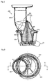
- Fig. 1 is a perspective view showing a juice extraction module for a juicer according to one embodiment of the present invention
- Fig. 2 is a sectional view showing the juice extraction module according to the embodiment of the present invention
- Fig. 3 is a plan view showing a lid of the juice extraction module shown in Fig. 1
- Fig. 4 is a sectional view of the lid taken along line A-A of Fig. 3
- Fig. 5 is a sectional view of the lid taken along line B-B of Fig. 3
- Fig. 6 is a front view showing a screw having a crushing portion provided on a top end thereof as a portion of juice extraction module shown in Fig. 1 .
- a juice extraction module for a juicer includes a container 100 having a juice extraction space defined therein and having a juice discharge port 101 and a residue discharge port 102 respectively formed in one and another sides of an outer surface thereof, a sieve 200 installed inside of the container 100 to separate juice from material residues generated in juice extraction, a screw 300 installed inside of the sieve 200 to extract juice from the material, and a lid 400 installed to a top end of the container 100 and formed with an input portion 410, through which a material is input.
- an opening/closing means for selectively opening and closing the juice discharge port 101 of the container 100 may be applied to the juice extraction module.
- a juice extraction module according to the invention also comprises a safety cover 700 which will be described in detail in reference to figures 7 to 11 .
- a cock valve may be used as the opening/closing means.
- the cock valve includes a valve body moving forward or backward in the juice discharge port 101, wherein a leading end of the valve body is preferably oriented toward the juice discharge port 101.
- the cock valve may include a juice discharge cock, which may be selectively connected to the juice discharge port 101 by the valve body.
- a crushing portion 500 is formed on a top end of the screw 300 to have a shape narrowed upward.
- the crushing portion 500 has further a crushing blade 510 formed thereon, wherein the crushing blade 510 extends in the shape of a spiral having a width gradually narrowed upward, more preferably toward a top apex of the crushing portion 500.
- a central shaft 310 of the screw 300 may be formed on the top apex of the crushing portion 500.
- the lid 400 has a crushing processing portion 600 formed in a bottom thereof to be concave upward from a face coupled with the container 100 in order to accommodate the crushing portion 500.
- the crushing processing portion 600 has a shape gradually narrowed toward a top apex corresponding to the crushing portion 500.
- top apex of the crushing processing portion 600 is formed with a shaft hole, into which the central shaft 310 of the screw 300 is rotatably fitted.
- the crushing processing portion 600 While being connected with the input portion 410, the crushing processing portion 600 cooperates with the crushing portion 500 to serve to crush the material input through the input portion 410.
- the crushing blade 510 is inserted and positioned in the crushing processing portion 600, and the crushing blade 510 cooperates with a specific shape of an inner surface of the crushing processing portion 600 to crush the material.
- the input portion 410 is offset toward one side with respect to a central axis of the screw 300 and simultaneously should have such a large bottom width W (or inner diameter) that a large-sized material such as an apple is allowed to be input without being chopped.
- the sieve 200 has the largest inner diameter at the top end thereof, and thus, a distance from the central axis of the screw 300 to the sieve 200 is set up to be largest at the top end of the sieve 200.
- the bottom width of the input portion 410 is set up to be larger than the shortest distance from the central axis of the screw 300 to an inner circumferential surface of the top end of the sieve 200.
- a region of the input portion 410 partially overlaps with a top end region of the sieve 200 and is out of the top end region of the sieve 200.
- the present invention has a large difference in that a conventional juicer has a small-sized input portion so as to be generally positioned inside of a region of a sieve.
- the crushing processing portion 600 is formed to cover the entire bottom region of the input portion 410 at the height of the crushing processing portion 600 connected to the bottom end of the input portion 410.
- the input portion 410 is within a circle region having a diameter corresponding to the diameter of the crushing processing portion 600 with the central shaft 310 of the screw 300 as the center, and more preferably, is positioned to be offset within one side of semicircle regions into which the circle region is divided by a line passing through the central shaft 310.
- the inner surface of the crushing processing portion 600 is formed to be gradually close to the crushing blade 510 of the crushing portion 500 in a direction in which the crushing blade 510 runs from the bottom end of the input portion 410.
- the material when the material is expelled out by the crushing blade 510, the material is held by the inner surface of the crushing processing portion 600, so that a lateral side of the material is crushed by the crushing blade 510, and the material is dragged into the crushing processing portion according to the rotation of the crushing portion.
- This provides an effect of automatically crushing the material even if a user inputs the material into the input portion 410 and then does not push the input material again.
- the crushing portion 500 further has one or more auxiliary crushing blades formed thereon so that they assist the crushing blade 510 to crush the material more effectively.
- the crushing blade 510 first crushes the material, and the auxiliary crushing blades may crush the material more finely.
- a material guide surface 620 is provided on the inner surface of the crushing processing portion 600 so that the material input through the input portion 410 can be guided to the sieve 200.
- the material guide surface 620 is provided as an element for smoothly connecting the sieve 200 and the input portion 410 extending to the outside to such an extent as to use an uncut apple as it is.
- the material guide surface 620 continues from the input portion 410 while overlapping with the input portion 410 and is formed to be inclined toward the central axis of the crushing portion 500, thereby causing a lateral side of the material to begin to be milled by the crushing blade 510.
- one or more milling blades 630 may be further formed on the crushing processing surface 610.
- the plurality of milling blades 630 are spaced apart from each other and extend from an upper portion of the crushing processing surface 610 to a lower portion thereof, and each of the milling blades 630 is gradually close to the crushing blade 510 as it goes from the upper portion toward the lower portion.
- the crushing portion 500 passes over the top end of the container 100 and sieve 200 and is accommodated and positioned in the crushing processing portion 600 positioned in the lid 400.
- the crushing portion 500 and the crushing processing portion 600 cooperate with each other to fully crush the material input through the input portion 410, thereby making it possible to smoothly extract juice from the material even if the user does not chop the material in advance.
- a lateral side of the material is processed by the crushing blade 510, which can be performed only by forming the crushing portion 500 to have a length suitable for the height of the material.
- the protruding length of the screw blade need not extend in order to cut the material itself.
- a sieve insertion step 420 may be formed in a bottom of the crushing processing portion 600 to be snugly fitted to the top end of the sieve 200.
- the bottom end of the material guide surface 620 meets the sieve insertion step 420 in a stepwise manner, wherein the bottom end of the material guide surface 620 is formed to conform to an inner surface of the top end of the sieve 200.
- the material crushed through the crushing processing portion 600 is smoothly guided into the sieve 200 along the material guide surface 620.
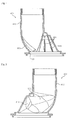
- Fig. 7 is a sectional view showing a juice extraction module for a juicer according to another embodiment of the present invention when a safety cover is in a first position
- Fig. 8 is a perspective view showing a lid of the juice extraction module for a juicer shown in Fig. 7 when the safety cover is in the first position
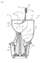
- Fig. 9 is a sectional view showing the juice extraction module for a juicer shown in Figs. 7 and 8 when the safety cover is in a second position
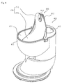
- Fig. 10 is a sectional view showing the juice extraction module for a juicer shown in Figs. 7 to 9 when the safety cover is in a third position
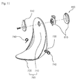
- Fig. 11 is an exploded perspective view illustrating the safety cover of the juice extraction module for a juicer shown in Figs. 7 to 10 .
- a juice extraction module for a juicer further includes a safety cover 700 and a modified structure of a top end of the input portion 410 related thereto as compared with the juice extraction module of the previous embodiment.
- the safety cover 700 and the modified structure of the top end of the input portion 410 are to solve a safety problem that may occur due to the enlarged area of the input portion 410 as described in the previous embodiment.
- the safety cover 700 and the modified structure are provided to prevent a person's hand from reaching the screw 500 through the input portion 410 in a process of inputting a material through the input portion 410 or regardless of the input of the material.
- the lid 400 is provided with the input portion 410.
- a main input opening 411 and a secondary input opening 412 having a size smaller than the main input opening 411 are formed in the top end of the input portion 410.
- the secondary input opening 412 may be formed to have a size compliant with current safety standards, and if necessary, may be eliminated.
- the safety cover 700 operates when a relatively large material is input through the main input opening 411, thereby securing user's safety.
- the safety cover 700 is formed to have an approximately "L"-shaped cross section and integrally includes a first cover portion 710 and a second cover portion 720 connected substantially perpendicularly to the first cover portion 710.
- the safety cover 700 is rotatably installed to the main input opening 411 while being formed to have a size to be accommodated in the top end of the input portion 410, more specifically, in the main input opening 411
- the safety cover 700 may be displaced between a first position of Figs. 7 and 8 , in which the first cover portion 710 almost fully opens the main input opening 411 by the rotation of the safety cover 700, a second position of Fig. 9 , in which the first cover portion 710 of the safety cover 700 covers the main input opening 411, and a third position of Fig. 10 , in which the first cover portion 710 and the second cover portion 720 at least partially cover the main input opening 411 and the secondary input opening 412, respectively.
- the safety cover 700 is provided with a pair of rotational shafts 730 at both sides of a position in which the first cover portion 710 and the second cover portion 720 are connected to each other.
- the pair of rotational shafts 730 are rotatably inserted into a pair of shaft grooves, which are formed in an upper inner surface of the input portion 410 (see Figs. 7 to 10 ) to face each other.
- the rotational shafts 730 and the shaft grooves constitute a hinge for rotatably supporting the safety cover 700.
- the shaft grooves, into which the rotational shafts are rotatably inserted are formed in both the sides of the safety cover 700, so that the hinge for rotatably supporting the safety cover 700 is defined.
- Torsion springs 740 are respectively installed to the rotational shafts 730, which are portions of the hinge of the safety cover 700.
- the torsion springs 740 provide the safety cover 700 with a bias force so that the safety cover 700 is biased to the first position (see Figs. 7 and 8 ), in which the first cover portion 710 is substantially vertically erected to almost fully open the main input opening 411 (see Figs. 7 to 12 ).
- the safety cover 700 When the material is input through the main input opening 411 of the input portion 410, the safety cover 700 may be rotated counterclockwise against the bias force of the torsion springs 740 by force of a person who inputs the material or by his or her hand, thereby being moved to the second position (see Fig. 9 ), or to the third position ( Fig. 10 ) to which the safety cover 700 is further rotated counterclockwise after passing the second position.
- the safety cover 700 can be maintained in the first position without additional external force, which helps the user input the material with ease.
- the rotation causes the material to be smoothly guided to the position, in which the material is processed by the screw 500.
- the second cover portion 720 is pushed, whereby the safety cover 700 is smoothly rotated and then moved to the vicinity of the second position of Fig. 9 , in which the first cover portion 710 blocks the main input opening 411 at the upper inner surface of the input portion 410.
- the rotation of the safety cover 700 stops and thus the hand or arm is maintained in the state that it is caught therebetween.
- the input portion 410 is blocked by the safety cover 700 so that the person's hand cannot move further.
- the juice extraction module for a juicer can essentially prevent the person's hand from reaching the screw 500 through the input portion 410.
- the juice extraction module for a juicer further includes a locking unit 800 for locking the safety cover 700 in the second position, in which the main input opening 411 is coved with the first cover portion 710 of the safety cover 700.
- the locking unit 800 includes a knob 810 positioned on an upper surface of the first cover portion 710 of the safety cover 700, and a locking piece 812 positioned on a lower surface of the first cover portion 710 and connected to the knob 810 by a connection portion penetrating the first cover portion 710.
- the locking unit 800 includes a locking groove 820 formed in the inner surface of the input portion 410 so that the locking piece 812 is selectively inserted into the locking groove 820.
- the locking piece 812 may be allowed to protrude outward from the edge of the first cover portion 710.
- the locking piece 812 is inserted into the locking groove 820 in such a protruding state of the locking piece 812, thereby locking the safety cover 700 in the second position shown in Figs. 9 and 10 .
- the input portion 410 is structured so that the center of the main input opening 411 in the upper part of the input portion 410 is offset from the center of the lower part thereof. That is, a material input path from the main input opening 411 to the lower part of the input portion 410 is defined in the form of an approximately " " shape.
- the " " " shaped material input path includes an upper path p1 vertically extending from the main input opening 411, a lower path p2 vertically extending downward from a position lower than the vertical upper path p1 to be offset from the upper path p1, and an approximately horizontal intermediate path p3 connecting the upper path p1 and the lower path p2.
- the upper path p1 is positioned vertically below the main input opening 411, and the lower path p3 is positioned vertically below the secondary input opening 412.
- Such a " " shaped material input path of the input portion 410 lengthens the entire length along which the material is input, thereby making it possible to prevent safety accident of infants or children. Also, a rotational radius of the safety cover 700 is secured in the secondary input opening 412 in which dust hardly collects, thereby effectively suppressing contamination of the safety cover 700.
Landscapes
- Engineering & Computer Science (AREA)
- Food Science & Technology (AREA)
- Life Sciences & Earth Sciences (AREA)
- Chemical & Material Sciences (AREA)
- Polymers & Plastics (AREA)
- Food-Manufacturing Devices (AREA)
- Closures For Containers (AREA)
- Apparatus For Making Beverages (AREA)
- Crushing And Pulverization Processes (AREA)
- Apparatuses For Bulk Treatment Of Fruits And Vegetables And Apparatuses For Preparing Feeds (AREA)
- Package Specialized In Special Use (AREA)
- Non-Alcoholic Beverages (AREA)
- Confectionery (AREA)
Priority Applications (3)
| Application Number | Priority Date | Filing Date | Title |
|---|---|---|---|
| RS20160886A RS55264B1 (sr) | 2013-01-14 | 2013-10-30 | Modul za izdvajanje soka za aparat za sokove |
| SI201330348A SI2810567T1 (sl) | 2013-01-14 | 2013-10-30 | Modul za ekstrakcijo soka za sokovnik |
| HRP20161322TT HRP20161322T1 (hr) | 2013-01-14 | 2016-10-11 | Modul za ekstrakciju soka za sokovnik |
Applications Claiming Priority (2)
| Application Number | Priority Date | Filing Date | Title |
|---|---|---|---|
| KR1020130004115A KR101300464B1 (ko) | 2013-01-14 | 2013-01-14 | 원액기용 착즙 모듈 |
| PCT/KR2013/009697 WO2014109465A1 (ko) | 2013-01-14 | 2013-10-30 | 원액기용 착즙 모듈 |
Publications (4)
| Publication Number | Publication Date |
|---|---|
| EP2810567A1 EP2810567A1 (en) | 2014-12-10 |
| EP2810567A4 EP2810567A4 (en) | 2015-05-13 |
| EP2810567B1 EP2810567B1 (en) | 2016-07-20 |
| EP2810567B9 true EP2810567B9 (en) | 2017-03-29 |
Family
ID=49221296
Family Applications (1)
| Application Number | Title | Priority Date | Filing Date |
|---|---|---|---|
| EP13854209.7A Active EP2810567B9 (en) | 2013-01-14 | 2013-10-30 | Juice-extraction module for juicing apparatus |
Country Status (33)
| Country | Link |
|---|---|
| US (1) | US8826812B2 (es) |
| EP (1) | EP2810567B9 (es) |
| JP (2) | JP2015505712A (es) |
| KR (1) | KR101300464B1 (es) |
| CN (1) | CN104053383B (es) |
| AU (1) | AU2013344338C1 (es) |
| BR (1) | BR112014012472B1 (es) |
| CA (1) | CA2874069C (es) |
| CL (1) | CL2015000664A1 (es) |
| CO (1) | CO7020886A2 (es) |
| CY (1) | CY1118247T1 (es) |
| DK (1) | DK2810567T5 (es) |
| ES (1) | ES2595505T3 (es) |
| HK (1) | HK1204754A1 (es) |
| HR (1) | HRP20161322T1 (es) |
| HU (1) | HUE029262T2 (es) |
| IL (1) | IL237510A (es) |
| LT (1) | LT2810567T (es) |
| MA (1) | MA37802B1 (es) |
| MX (1) | MX339450B (es) |
| MY (1) | MY155341A (es) |
| NZ (1) | NZ625383A (es) |
| PH (1) | PH12014501141B1 (es) |
| PL (1) | PL2810567T3 (es) |
| PT (1) | PT2810567T (es) |
| RS (1) | RS55264B1 (es) |
| RU (1) | RU2568473C1 (es) |
| SA (1) | SA515360062B1 (es) |
| SG (1) | SG11201402573PA (es) |
| SI (1) | SI2810567T1 (es) |
| TW (2) | TWI535403B (es) |
| WO (1) | WO2014109465A1 (es) |
| ZA (1) | ZA201403322B (es) |
Families Citing this family (23)
| Publication number | Priority date | Publication date | Assignee | Title |
|---|---|---|---|---|
| TWI516239B (zh) * | 2012-06-29 | 2016-01-11 | 金煐麒 | 果汁壓榨萃取機 |
| US9332881B2 (en) * | 2014-01-17 | 2016-05-10 | Capbran Holdings, Llc | Food mixer |
| KR102257330B1 (ko) | 2014-04-28 | 2021-05-31 | 코웨이 주식회사 | 안전 투입장치를 구비한 착즙 스크류 조립체 |
| KR102257331B1 (ko) | 2014-05-14 | 2021-05-31 | 코웨이 주식회사 | 안전 개폐 구조를 가진 투입장치 |
| KR102257333B1 (ko) | 2014-05-21 | 2021-05-31 | 코웨이 주식회사 | 회전가능한 일체형 구조를 가진 커버 |
| KR102261630B1 (ko) | 2014-06-24 | 2021-06-08 | 코웨이 주식회사 | 탈착식 안전 투입장치 |
| CN204049194U (zh) * | 2014-08-29 | 2014-12-31 | 宁波泰尔斯电子实业有限公司 | 榨汁机及其下料装置 |
| WO2016091182A1 (zh) * | 2014-12-12 | 2016-06-16 | 九阳股份有限公司 | 一种螺杆挤压榨汁机 |
| CN104545397A (zh) * | 2015-02-06 | 2015-04-29 | 宁波世林国际贸易有限公司 | 榨汁机的双口进料筒 |
| KR102389754B1 (ko) * | 2015-03-30 | 2022-04-25 | 코웨이 주식회사 | 안전 투입구 및 이를 포함하는 주서기 |
| CN104814652B (zh) * | 2015-05-15 | 2017-08-04 | 廖玉连 | 原汁机 |
| CN106308433B (zh) * | 2015-06-24 | 2018-06-26 | 浙江绍兴苏泊尔生活电器有限公司 | 螺杆及具有其的原汁机 |
| CN106942992B (zh) * | 2016-01-06 | 2019-02-26 | 浙江绍兴苏泊尔生活电器有限公司 | 进料筒及具有其的料理机 |
| CN107343736B (zh) * | 2016-05-07 | 2020-05-12 | 广东艾诗凯奇智能科技有限公司 | 原汁机及其汁液提取模块 |
| CN206729714U (zh) * | 2017-01-05 | 2017-12-12 | 刘建军 | 用于榨汁机的汁液提取模块 |
| CN109567549B (zh) * | 2017-09-28 | 2022-01-11 | 广东美的生活电器制造有限公司 | 食物处理机 |
| CN107713693A (zh) * | 2017-11-08 | 2018-02-23 | 江门市鸿裕达电机电器制造有限公司 | 一种榨汁机构 |
| FR3087103B1 (fr) | 2018-10-12 | 2020-10-02 | Seb Sa | Dispositif d'introduction d'aliments securise et appareil de preparation culinaire comportant un tel dispositif |
| FR3101235B1 (fr) | 2019-09-27 | 2021-08-27 | Seb Sa | Dispositif d’introduction d’aliments securise et appareil de preparation culinaire comportant un tel dispositif |
| AU2022256104A1 (en) * | 2021-10-27 | 2023-05-18 | Nuc Electronics Co., Ltd. | Double input structure juice module and screw |
| KR102503265B1 (ko) * | 2021-12-08 | 2023-02-27 | 주식회사 엔유씨전자 | 이중투입구조 착즙모듈 및 스크류 |
| KR102511027B1 (ko) * | 2021-10-27 | 2023-03-24 | 주식회사 엔유씨전자 | 이중투입구조 착즙모듈 및 스크류 |
| CN115254265B (zh) * | 2022-07-29 | 2023-05-09 | 马鞍山江心绿洲食品有限公司 | 一种豆干加工用磨浆离心机 |
Family Cites Families (58)
| Publication number | Priority date | Publication date | Assignee | Title |
|---|---|---|---|---|
| US1906054A (en) | 1930-04-22 | 1933-04-25 | Ira J Dodge | Fruit juice extractor |
| DE655658C (de) * | 1936-12-18 | 1938-01-20 | Eugen Schmidt | In das Gehaeuse einer Hauschaltzerkleinerungsmaschine einzusetzende Fruchtpresse mit Pressschnecke |
| US2304929A (en) | 1938-09-10 | 1942-12-15 | Clinton G Keith | Centrifugal liquid extractor |
| US2479194A (en) | 1945-10-29 | 1949-08-16 | Eastman Nathaniel | Fruit-cutting and juice-expressing machine |
| US2599464A (en) * | 1946-03-04 | 1952-06-03 | Robert E Larsen | Citrus fruit juicer |
| US2495309A (en) | 1946-12-13 | 1950-01-24 | Butler Brothers | Food grinder having a split casing |
| GB925773A (en) * | 1960-03-15 | 1963-05-08 | Renato Lanzanova | Improvements in or relating to the treatment of foodstuffs |
| US4440074A (en) | 1982-01-25 | 1984-04-03 | Tokyo Denki Kabushiki Kaisha | Juice extractor |
| JPS59192314A (ja) * | 1983-04-14 | 1984-10-31 | 松下電器産業株式会社 | 調理機 |
| JPS6040025A (ja) * | 1983-08-12 | 1985-03-02 | 松下電器産業株式会社 | 調理機 |
| US5262834A (en) | 1988-12-06 | 1993-11-16 | Canon Kabushiki Kaisha | Image fixing apparatus |
| KR950000072B1 (ko) | 1989-07-31 | 1995-01-09 | 제일합섬 주식회사 | 고내열성 실록산 폴리이미드막의 형성방법 |
| KR960000061Y1 (ko) * | 1993-03-16 | 1996-01-04 | 김춘자 | 착즙기 |
| CA2119495A1 (en) | 1993-03-29 | 1994-09-30 | David N. Anderson | Fruit and vegetable juice extractor |
| KR960003085Y1 (ko) | 1993-11-16 | 1996-04-16 | 김종길 | 다단 세절분쇄식 착즙기(多端 細分粉碎式 搾汁機) |
| US5669289A (en) | 1996-12-30 | 1997-09-23 | Chen; Tse-Hsiung | Strainer assembly |
| KR100227755B1 (ko) | 1997-08-20 | 1999-11-01 | 전주범 | 냉장고 도어의 보조 개방장치 |
| US5906154A (en) | 1997-11-25 | 1999-05-25 | Dong-A Engineering Co., Ltd. | Juice extractor |
| US5970860A (en) | 1999-01-08 | 1999-10-26 | Yip; Chung Lun | Food processor |
| KR100285120B1 (ko) | 1999-01-25 | 2001-03-15 | 윤정규 | 녹즙기의 착즙장치 |
| KR20000074261A (ko) | 1999-05-19 | 2000-12-15 | 김성수 | 과일 착즙기 |
| KR100340696B1 (ko) * | 1999-11-25 | 2002-06-20 | 이상용 | 폐기문서 세단기의 이중투입구장치 |
| DE10016297A1 (de) | 2000-03-31 | 2001-10-04 | Bsh Bosch Siemens Hausgeraete | Küchenmaschine |
| KR100390033B1 (ko) | 2001-01-06 | 2003-07-07 | 주식회사 동아오스카 | 착즙기와 착즙기용 하우징 |
| JP3081171U (ja) * | 2001-04-18 | 2001-10-26 | 良秀 明日 | ジューサ |
| KR200274699Y1 (ko) | 2002-02-15 | 2002-05-04 | 김영기 | 착즙 분쇄기 |
| RU2218061C1 (ru) * | 2002-03-14 | 2003-12-10 | Кочнев Николай Константинович | Способ переработки клубней топинамбура |
| JP2004016694A (ja) * | 2002-06-20 | 2004-01-22 | Matsushita Electric Ind Co Ltd | 電動調理機 |
| TWI250851B (en) | 2003-05-09 | 2006-03-11 | Tzuen-Yu Jan | Juice extractor |
| KR200322266Y1 (ko) | 2003-05-20 | 2003-08-09 | 김영기 | 착즙 분쇄기 |
| AU2003903367A0 (en) * | 2003-07-02 | 2003-07-17 | Breville Pty. Ltd. | Juicer |
| US6817750B1 (en) * | 2003-08-26 | 2004-11-16 | Homeland Housewares, Llc | Individualized blender |
| KR100611302B1 (ko) | 2004-09-18 | 2006-08-10 | 김영기 | 착즙분쇄기 |
| KR200376615Y1 (ko) | 2004-12-02 | 2005-03-11 | 조해준 | 식품 분쇄기 |
| KR100793852B1 (ko) | 2005-03-21 | 2008-01-11 | 김영기 | 착즙주스기 |
| KR200392588Y1 (ko) | 2005-05-24 | 2005-08-19 | (주)한국하비비 | 스틸 칼날이 고정된 주서기 덮개 |
| KR20050101127A (ko) | 2005-09-07 | 2005-10-20 | 김형수 | 다기능 녹즙기 |
| KR100755440B1 (ko) | 2006-06-21 | 2007-09-05 | 김영기 | 착즙주스기 |
| JP3130025U (ja) * | 2006-12-27 | 2007-03-08 | 律展企業股▲ふん▼有限公司 | 多機能フードプロセッサー |
| US7461801B2 (en) * | 2007-01-05 | 2008-12-09 | Lyu Jan Co., Ltd. | Multi-functional food processor |
| FR2912633A1 (fr) * | 2007-02-19 | 2008-08-22 | Ekono Sarl | Appareil de cuisson et d'egouttage d'aliments contenus dans un liquide comprenant des perforations d'evaporation et des perforations d'egouttage |
| FR2932665B1 (fr) | 2008-06-24 | 2013-05-31 | Seb Sa | Appareil electromenager de preparation de jus. |
| EP2328445B1 (en) | 2008-09-09 | 2017-07-12 | Adrian Rivera | Automated juice extractor |
| RU2448633C1 (ru) * | 2009-08-28 | 2012-04-27 | Ньюк Электроникс Ко., Лтд. | Модуль соковыжималки и соковыжималка с вертикальным шнеком |
| KR100966607B1 (ko) | 2009-08-28 | 2010-06-29 | 주식회사 엔유씨전자 | 주서 스크류 및 이를 포함하는 주서 모듈 |
| CN201767733U (zh) | 2010-06-13 | 2011-03-23 | 杨碧连 | 一种螺杆挤压式新型榨汁机 |
| KR101159176B1 (ko) * | 2010-09-17 | 2012-06-22 | 김영기 | 찌꺼기개폐기구가 구비된 주스기 |
| JP5535335B2 (ja) * | 2010-09-17 | 2014-07-02 | ヨンキ キム | スムージーメーカー兼用のジューサー |
| KR101820042B1 (ko) | 2010-10-25 | 2018-01-18 | 코웨이 주식회사 | 스크류 어셈블리를 포함하는 주서기 |
| AU2011321202B2 (en) | 2010-10-25 | 2016-05-12 | Coway Co., Ltd. | Juicer having juice extracting screw assembly |
| FR2967034B1 (fr) | 2010-11-09 | 2013-08-23 | Seb Sa | Appareil electromenager de preparation culinaire comportant une vis de pressage |
| KR200454079Y1 (ko) | 2011-02-10 | 2011-06-15 | (주)현대가전업 | 수직형 녹즙기의 다짐용 보조 용기 |
| US9066618B2 (en) | 2011-03-07 | 2015-06-30 | Tongyang Magic Inc. | Apparatus for extracting juice |
| CN103040348A (zh) | 2011-10-11 | 2013-04-17 | 广东德豪润达电气股份有限公司 | 榨汁机 |
| CN202312788U (zh) * | 2011-11-22 | 2012-07-11 | 江苏顺发电器有限公司 | 一种低噪音的榨汁机 |
| CN103202653B (zh) | 2012-01-17 | 2015-07-15 | 唐锋机电科技(深圳)有限公司 | 一种榨汁机 |
| KR20120054572A (ko) | 2012-04-09 | 2012-05-30 | 김영기 | 찌꺼기개폐기구가 구비된 주스기 |
| KR101270140B1 (ko) * | 2012-11-09 | 2013-05-31 | 주식회사 엔유씨전자 | 원액기용 착즙모듈 |
-
2013
- 2013-01-14 KR KR1020130004115A patent/KR101300464B1/ko active IP Right Grant
- 2013-08-12 US US13/964,822 patent/US8826812B2/en active Active
- 2013-10-30 MX MX2014006198A patent/MX339450B/es active IP Right Grant
- 2013-10-30 PT PT138542097T patent/PT2810567T/pt unknown
- 2013-10-30 MY MYPI2014701333A patent/MY155341A/en unknown
- 2013-10-30 SG SG11201402573PA patent/SG11201402573PA/en unknown
- 2013-10-30 JP JP2014556498A patent/JP2015505712A/ja not_active Withdrawn
- 2013-10-30 AU AU2013344338A patent/AU2013344338C1/en not_active Ceased
- 2013-10-30 ES ES13854209.7T patent/ES2595505T3/es active Active
- 2013-10-30 CA CA2874069A patent/CA2874069C/en active Active
- 2013-10-30 SI SI201330348A patent/SI2810567T1/sl unknown
- 2013-10-30 PL PL13854209T patent/PL2810567T3/pl unknown
- 2013-10-30 WO PCT/KR2013/009697 patent/WO2014109465A1/ko active Application Filing
- 2013-10-30 DK DK13854209.7T patent/DK2810567T5/en active
- 2013-10-30 RU RU2014123722/13A patent/RU2568473C1/ru active
- 2013-10-30 CN CN201380003960.7A patent/CN104053383B/zh active Active
- 2013-10-30 EP EP13854209.7A patent/EP2810567B9/en active Active
- 2013-10-30 HU HUE13854209A patent/HUE029262T2/en unknown
- 2013-10-30 LT LTEP13854209.7T patent/LT2810567T/lt unknown
- 2013-10-30 NZ NZ625383A patent/NZ625383A/en unknown
- 2013-10-30 BR BR112014012472-8A patent/BR112014012472B1/pt not_active IP Right Cessation
- 2013-10-30 RS RS20160886A patent/RS55264B1/sr unknown
-
2014
- 2014-01-13 TW TW103101151A patent/TWI535403B/zh active
- 2014-01-13 TW TW103200691U patent/TWM486361U/zh unknown
- 2014-05-09 ZA ZA2014/03322A patent/ZA201403322B/en unknown
- 2014-05-22 CO CO14110178A patent/CO7020886A2/es active IP Right Grant
- 2014-05-22 PH PH12014501141A patent/PH12014501141B1/en unknown
-
2015
- 2015-01-21 MA MA37802A patent/MA37802B1/fr unknown
- 2015-02-17 JP JP2015029024A patent/JP6095133B2/ja active Active
- 2015-02-23 SA SA515360062A patent/SA515360062B1/ar unknown
- 2015-03-02 IL IL237510A patent/IL237510A/en active IP Right Grant
- 2015-03-17 CL CL2015000664A patent/CL2015000664A1/es unknown
- 2015-06-04 HK HK15105332.9A patent/HK1204754A1/zh not_active IP Right Cessation
-
2016
- 2016-10-11 HR HRP20161322TT patent/HRP20161322T1/hr unknown
- 2016-10-13 CY CY20161101027T patent/CY1118247T1/el unknown
Also Published As
Similar Documents
| Publication | Publication Date | Title |
|---|---|---|
| EP2810567B1 (en) | Juice-extraction module for juicing apparatus | |
| US11147303B2 (en) | Juice extraction module for juicer | |
| AU2020101778B4 (en) | Juice extraction module for juicer | |
| AU2013342295B2 (en) | Juice extraction module for juicer |
Legal Events
| Date | Code | Title | Description |
|---|---|---|---|
| PUAI | Public reference made under article 153(3) epc to a published international application that has entered the european phase |
Free format text: ORIGINAL CODE: 0009012 |
|
| 17P | Request for examination filed |
Effective date: 20140522 |
|
| AK | Designated contracting states |
Kind code of ref document: A1 Designated state(s): AL AT BE BG CH CY CZ DE DK EE ES FI FR GB GR HR HU IE IS IT LI LT LU LV MC MK MT NL NO PL PT RO RS SE SI SK SM TR |
|
| AX | Request for extension of the european patent |
Extension state: BA ME |
|
| RA4 | Supplementary search report drawn up and despatched (corrected) |
Effective date: 20150414 |
|
| RIC1 | Information provided on ipc code assigned before grant |
Ipc: A23N 1/02 20060101ALI20150408BHEP Ipc: A23N 1/00 20060101AFI20150408BHEP Ipc: A47J 19/02 20060101ALI20150408BHEP |
|
| REG | Reference to a national code |
Ref country code: HK Ref legal event code: DE Ref document number: 1204754 Country of ref document: HK |
|
| GRAP | Despatch of communication of intention to grant a patent |
Free format text: ORIGINAL CODE: EPIDOSNIGR1 |
|
| RIC1 | Information provided on ipc code assigned before grant |
Ipc: A23N 1/00 20060101AFI20160127BHEP Ipc: A47J 19/02 20060101ALI20160127BHEP Ipc: A23N 1/02 20060101ALI20160127BHEP |
|
| INTG | Intention to grant announced |
Effective date: 20160229 |
|
| DAX | Request for extension of the european patent (deleted) | ||
| GRAS | Grant fee paid |
Free format text: ORIGINAL CODE: EPIDOSNIGR3 |
|
| GRAA | (expected) grant |
Free format text: ORIGINAL CODE: 0009210 |
|
| STAA | Information on the status of an ep patent application or granted ep patent |
Free format text: STATUS: THE PATENT HAS BEEN GRANTED |
|
| AK | Designated contracting states |
Kind code of ref document: B1 Designated state(s): AL AT BE BG CH CY CZ DE DK EE ES FI FR GB GR HR HU IE IS IT LI LT LU LV MC MK MT NL NO PL PT RO RS SE SI SK SM TR |
|
| REG | Reference to a national code |
Ref country code: GB Ref legal event code: FG4D |
|
| REG | Reference to a national code |
Ref country code: CH Ref legal event code: EP |
|
| REG | Reference to a national code |
Ref country code: IE Ref legal event code: FG4D |
|
| REG | Reference to a national code |
Ref country code: AT Ref legal event code: REF Ref document number: 813247 Country of ref document: AT Kind code of ref document: T Effective date: 20160815 |
|
| REG | Reference to a national code |
Ref country code: DE Ref legal event code: R096 Ref document number: 602013009735 Country of ref document: DE |
|
| REG | Reference to a national code |
Ref country code: NL Ref legal event code: FP |
|
| REG | Reference to a national code |
Ref country code: DK Ref legal event code: T3 Effective date: 20161004 |
|
| REG | Reference to a national code |
Ref country code: HR Ref legal event code: TUEP Ref document number: P20161322 Country of ref document: HR |
|
| REG | Reference to a national code |
Ref country code: RO Ref legal event code: EPE |
|
| REG | Reference to a national code |
Ref country code: FR Ref legal event code: PLFP Year of fee payment: 4 |
|
| REG | Reference to a national code |
Ref country code: PT Ref legal event code: SC4A Ref document number: 2810567 Country of ref document: PT Date of ref document: 20161025 Kind code of ref document: T Free format text: AVAILABILITY OF NATIONAL TRANSLATION Effective date: 20161018 |
|
| REG | Reference to a national code |
Ref country code: CH Ref legal event code: NV Representative=s name: MICHELI AND CIE SA, CH |
|
| REG | Reference to a national code |
Ref country code: SE Ref legal event code: TRGR |
|
| REG | Reference to a national code |
Ref country code: HR Ref legal event code: T1PR Ref document number: P20161322 Country of ref document: HR |
|
| REG | Reference to a national code |
Ref country code: NO Ref legal event code: T2 Effective date: 20160720 |
|
| REG | Reference to a national code |
Ref country code: EE Ref legal event code: FG4A Ref document number: E012558 Country of ref document: EE Effective date: 20161020 |
|
| REG | Reference to a national code |
Ref country code: ES Ref legal event code: FG2A Ref document number: 2595505 Country of ref document: ES Kind code of ref document: T3 Effective date: 20161230 |
|
| REG | Reference to a national code |
Ref country code: DK Ref legal event code: T5 Effective date: 20170118 |
|
| PG25 | Lapsed in a contracting state [announced via postgrant information from national office to epo] |
Ref country code: IS Free format text: LAPSE BECAUSE OF FAILURE TO SUBMIT A TRANSLATION OF THE DESCRIPTION OR TO PAY THE FEE WITHIN THE PRESCRIBED TIME-LIMIT Effective date: 20161120 |
|
| REG | Reference to a national code |
Ref country code: HU Ref legal event code: AG4A Ref document number: E029262 Country of ref document: HU |
|
| REG | Reference to a national code |
Ref country code: GR Ref legal event code: EP Ref document number: 20160402539 Country of ref document: GR Effective date: 20170130 |
|
| REG | Reference to a national code |
Ref country code: NO Ref legal event code: TB2 |
|
| REG | Reference to a national code |
Ref country code: DE Ref legal event code: R026 Ref document number: 602013009735 Country of ref document: DE |
|
| REG | Reference to a national code |
Ref country code: HK Ref legal event code: GR Ref document number: 1204754 Country of ref document: HK |
|
| PLBI | Opposition filed |
Free format text: ORIGINAL CODE: 0009260 |
|
| PLAX | Notice of opposition and request to file observation + time limit sent |
Free format text: ORIGINAL CODE: EPIDOSNOBS2 |
|
| 26 | Opposition filed |
Opponent name: SCHLIEF, THOMAS P. Effective date: 20170419 |
|
| PG25 | Lapsed in a contracting state [announced via postgrant information from national office to epo] |
Ref country code: SM Free format text: LAPSE BECAUSE OF FAILURE TO SUBMIT A TRANSLATION OF THE DESCRIPTION OR TO PAY THE FEE WITHIN THE PRESCRIBED TIME-LIMIT Effective date: 20160720 |
|
| PLBB | Reply of patent proprietor to notice(s) of opposition received |
Free format text: ORIGINAL CODE: EPIDOSNOBS3 |
|
| REG | Reference to a national code |
Ref country code: FR Ref legal event code: PLFP Year of fee payment: 5 |
|
| REG | Reference to a national code |
Ref country code: SK Ref legal event code: T3 Ref document number: E 25326 Country of ref document: SK |
|
| REG | Reference to a national code |
Ref country code: SK Ref legal event code: T4 Ref document number: E 25326 Country of ref document: SK |
|
| REG | Reference to a national code |
Ref country code: FR Ref legal event code: PLFP Year of fee payment: 6 |
|
| PLCK | Communication despatched that opposition was rejected |
Free format text: ORIGINAL CODE: EPIDOSNREJ1 |
|
| STAA | Information on the status of an ep patent application or granted ep patent |
Free format text: STATUS: THE PATENT HAS BEEN GRANTED |
|
| PG25 | Lapsed in a contracting state [announced via postgrant information from national office to epo] |
Ref country code: AL Free format text: LAPSE BECAUSE OF FAILURE TO SUBMIT A TRANSLATION OF THE DESCRIPTION OR TO PAY THE FEE WITHIN THE PRESCRIBED TIME-LIMIT Effective date: 20160720 |
|
| APBM | Appeal reference recorded |
Free format text: ORIGINAL CODE: EPIDOSNREFNO |
|
| APBP | Date of receipt of notice of appeal recorded |
Free format text: ORIGINAL CODE: EPIDOSNNOA2O |
|
| APAH | Appeal reference modified |
Free format text: ORIGINAL CODE: EPIDOSCREFNO |
|
| APBQ | Date of receipt of statement of grounds of appeal recorded |
Free format text: ORIGINAL CODE: EPIDOSNNOA3O |
|
| PGFP | Annual fee paid to national office [announced via postgrant information from national office to epo] |
Ref country code: MK Payment date: 20180912 Year of fee payment: 6 |
|
| REG | Reference to a national code |
Ref country code: HR Ref legal event code: ODRP Ref document number: P20161322 Country of ref document: HR Payment date: 20190913 Year of fee payment: 7 |
|
| REG | Reference to a national code |
Ref country code: HR Ref legal event code: ODRP Ref document number: P20161322 Country of ref document: HR Payment date: 20200915 Year of fee payment: 8 |
|
| REG | Reference to a national code |
Ref country code: DE Ref legal event code: R100 Ref document number: 602013009735 Country of ref document: DE |
|
| APBU | Appeal procedure closed |
Free format text: ORIGINAL CODE: EPIDOSNNOA9O |
|
| PLAB | Opposition data, opponent's data or that of the opponent's representative modified |
Free format text: ORIGINAL CODE: 0009299OPPO |
|
| PLBN | Opposition rejected |
Free format text: ORIGINAL CODE: 0009273 |
|
| STAA | Information on the status of an ep patent application or granted ep patent |
Free format text: STATUS: OPPOSITION REJECTED |
|
| R26 | Opposition filed (corrected) |
Opponent name: SCHLIEF, THOMAS P. Effective date: 20170419 |
|
| 27O | Opposition rejected |
Effective date: 20210203 |
|
| REG | Reference to a national code |
Ref country code: AT Ref legal event code: UEP Ref document number: 813247 Country of ref document: AT Kind code of ref document: T Effective date: 20160720 |
|
| PGFP | Annual fee paid to national office [announced via postgrant information from national office to epo] |
Ref country code: FI Payment date: 20210920 Year of fee payment: 9 Ref country code: IE Payment date: 20210927 Year of fee payment: 9 Ref country code: LU Payment date: 20210920 Year of fee payment: 9 Ref country code: MC Payment date: 20210922 Year of fee payment: 9 |
|
| REG | Reference to a national code |
Ref country code: HR Ref legal event code: ODRP Ref document number: P20161322 Country of ref document: HR Payment date: 20210913 Year of fee payment: 9 |
|
| PGFP | Annual fee paid to national office [announced via postgrant information from national office to epo] |
Ref country code: RO Payment date: 20210928 Year of fee payment: 9 Ref country code: GR Payment date: 20210920 Year of fee payment: 9 Ref country code: TR Payment date: 20210914 Year of fee payment: 9 |
|
| PGFP | Annual fee paid to national office [announced via postgrant information from national office to epo] |
Ref country code: PT Payment date: 20210917 Year of fee payment: 9 |
|
| PGFP | Annual fee paid to national office [announced via postgrant information from national office to epo] |
Ref country code: AT Payment date: 20210920 Year of fee payment: 9 Ref country code: CY Payment date: 20210914 Year of fee payment: 9 Ref country code: BG Payment date: 20211025 Year of fee payment: 9 Ref country code: SE Payment date: 20211006 Year of fee payment: 9 Ref country code: ES Payment date: 20211105 Year of fee payment: 9 Ref country code: NO Payment date: 20211001 Year of fee payment: 9 |
|
| PGFP | Annual fee paid to national office [announced via postgrant information from national office to epo] |
Ref country code: LV Payment date: 20211022 Year of fee payment: 9 Ref country code: HU Payment date: 20210918 Year of fee payment: 9 Ref country code: BE Payment date: 20211029 Year of fee payment: 9 |
|
| PGFP | Annual fee paid to national office [announced via postgrant information from national office to epo] |
Ref country code: MT Payment date: 20210910 Year of fee payment: 9 |
|
| PGFP | Annual fee paid to national office [announced via postgrant information from national office to epo] |
Ref country code: SK Payment date: 20220907 Year of fee payment: 10 Ref country code: LT Payment date: 20220907 Year of fee payment: 10 Ref country code: HR Payment date: 20220912 Year of fee payment: 10 Ref country code: EE Payment date: 20220908 Year of fee payment: 10 Ref country code: CZ Payment date: 20220907 Year of fee payment: 10 |
|
| REG | Reference to a national code |
Ref country code: HR Ref legal event code: ODRP Ref document number: P20161322 Country of ref document: HR Payment date: 20220912 Year of fee payment: 10 |
|
| PGFP | Annual fee paid to national office [announced via postgrant information from national office to epo] |
Ref country code: RS Payment date: 20220909 Year of fee payment: 10 |
|
| PGFP | Annual fee paid to national office [announced via postgrant information from national office to epo] |
Ref country code: SI Payment date: 20220913 Year of fee payment: 10 |
|
| REG | Reference to a national code |
Ref country code: DE Ref legal event code: R082 Ref document number: 602013009735 Country of ref document: DE Representative=s name: CBDL PATENTANWAELTE GBR, DE |
|
| REG | Reference to a national code |
Ref country code: NO Ref legal event code: MMEP Ref country code: SE Ref legal event code: EUG |
|
| PG25 | Lapsed in a contracting state [announced via postgrant information from national office to epo] |
Ref country code: MC Free format text: LAPSE BECAUSE OF NON-PAYMENT OF DUE FEES Effective date: 20221031 |
|
| REG | Reference to a national code |
Ref country code: AT Ref legal event code: MM01 Ref document number: 813247 Country of ref document: AT Kind code of ref document: T Effective date: 20221030 |
|
| REG | Reference to a national code |
Ref country code: BE Ref legal event code: MM Effective date: 20221031 |
|
| PG25 | Lapsed in a contracting state [announced via postgrant information from national office to epo] |
Ref country code: LU Free format text: LAPSE BECAUSE OF NON-PAYMENT OF DUE FEES Effective date: 20221030 |
|
| P01 | Opt-out of the competence of the unified patent court (upc) registered |
Effective date: 20230530 |
|
| PG25 | Lapsed in a contracting state [announced via postgrant information from national office to epo] |
Ref country code: RO Free format text: LAPSE BECAUSE OF NON-PAYMENT OF DUE FEES Effective date: 20221030 Ref country code: PT Free format text: LAPSE BECAUSE OF NON-PAYMENT OF DUE FEES Effective date: 20230502 Ref country code: NO Free format text: LAPSE BECAUSE OF NON-PAYMENT OF DUE FEES Effective date: 20221031 Ref country code: LV Free format text: LAPSE BECAUSE OF NON-PAYMENT OF DUE FEES Effective date: 20221030 Ref country code: HU Free format text: LAPSE BECAUSE OF NON-PAYMENT OF DUE FEES Effective date: 20221031 Ref country code: CY Free format text: LAPSE BECAUSE OF NON-PAYMENT OF DUE FEES Effective date: 20221030 Ref country code: AT Free format text: LAPSE BECAUSE OF NON-PAYMENT OF DUE FEES Effective date: 20221030 |
|
| PG25 | Lapsed in a contracting state [announced via postgrant information from national office to epo] |
Ref country code: SE Free format text: LAPSE BECAUSE OF NON-PAYMENT OF DUE FEES Effective date: 20221031 Ref country code: GR Free format text: LAPSE BECAUSE OF NON-PAYMENT OF DUE FEES Effective date: 20230508 |
|
| PG25 | Lapsed in a contracting state [announced via postgrant information from national office to epo] |
Ref country code: BE Free format text: LAPSE BECAUSE OF NON-PAYMENT OF DUE FEES Effective date: 20221031 |
|
| PG25 | Lapsed in a contracting state [announced via postgrant information from national office to epo] |
Ref country code: IE Free format text: LAPSE BECAUSE OF NON-PAYMENT OF DUE FEES Effective date: 20221030 |
|
| PGFP | Annual fee paid to national office [announced via postgrant information from national office to epo] |
Ref country code: NL Payment date: 20230926 Year of fee payment: 11 |
|
| PGFP | Annual fee paid to national office [announced via postgrant information from national office to epo] |
Ref country code: PL Payment date: 20230908 Year of fee payment: 11 Ref country code: FR Payment date: 20230725 Year of fee payment: 11 Ref country code: DK Payment date: 20230927 Year of fee payment: 11 |
|
| REG | Reference to a national code |
Ref country code: ES Ref legal event code: FD2A Effective date: 20231207 |
|
| PGFP | Annual fee paid to national office [announced via postgrant information from national office to epo] |
Ref country code: GB Payment date: 20231019 Year of fee payment: 11 |
|
| PG25 | Lapsed in a contracting state [announced via postgrant information from national office to epo] |
Ref country code: ES Free format text: LAPSE BECAUSE OF NON-PAYMENT OF DUE FEES Effective date: 20221031 |
|
| PG25 | Lapsed in a contracting state [announced via postgrant information from national office to epo] |
Ref country code: ES Free format text: LAPSE BECAUSE OF NON-PAYMENT OF DUE FEES Effective date: 20221031 |
|
| PGFP | Annual fee paid to national office [announced via postgrant information from national office to epo] |
Ref country code: IT Payment date: 20231009 Year of fee payment: 11 Ref country code: DE Payment date: 20231011 Year of fee payment: 11 Ref country code: CH Payment date: 20231102 Year of fee payment: 11 |
|
| PG25 | Lapsed in a contracting state [announced via postgrant information from national office to epo] |
Ref country code: FI Free format text: LAPSE BECAUSE OF NON-PAYMENT OF DUE FEES Effective date: 20221030 |
|
| REG | Reference to a national code |
Ref country code: HR Ref legal event code: PBON Ref document number: P20161322 Country of ref document: HR Effective date: 20231030 |
|
| REG | Reference to a national code |
Ref country code: EE Ref legal event code: MM4A Ref document number: E012558 Country of ref document: EE Effective date: 20231031 |