EP2809864B1 - Seuil accessible aux handicapés, en particulier seuil d'une construction ancienne ou d'un logement rénové - Google Patents
Seuil accessible aux handicapés, en particulier seuil d'une construction ancienne ou d'un logement rénové Download PDFInfo
- Publication number
- EP2809864B1 EP2809864B1 EP13705934.1A EP13705934A EP2809864B1 EP 2809864 B1 EP2809864 B1 EP 2809864B1 EP 13705934 A EP13705934 A EP 13705934A EP 2809864 B1 EP2809864 B1 EP 2809864B1
- Authority
- EP
- European Patent Office
- Prior art keywords
- threshold
- floor
- base body
- leg
- door
- Prior art date
- Legal status (The legal status is an assumption and is not a legal conclusion. Google has not performed a legal analysis and makes no representation as to the accuracy of the status listed.)
- Active
Links
Images






Classifications
-
- E—FIXED CONSTRUCTIONS
- E06—DOORS, WINDOWS, SHUTTERS, OR ROLLER BLINDS IN GENERAL; LADDERS
- E06B—FIXED OR MOVABLE CLOSURES FOR OPENINGS IN BUILDINGS, VEHICLES, FENCES OR LIKE ENCLOSURES IN GENERAL, e.g. DOORS, WINDOWS, BLINDS, GATES
- E06B7/00—Special arrangements or measures in connection with doors or windows
- E06B7/14—Measures for draining-off condensed water or water leaking-in frame members for draining off condensation water, throats at the bottom of a sash
-
- E—FIXED CONSTRUCTIONS
- E06—DOORS, WINDOWS, SHUTTERS, OR ROLLER BLINDS IN GENERAL; LADDERS
- E06B—FIXED OR MOVABLE CLOSURES FOR OPENINGS IN BUILDINGS, VEHICLES, FENCES OR LIKE ENCLOSURES IN GENERAL, e.g. DOORS, WINDOWS, BLINDS, GATES
- E06B1/00—Border constructions of openings in walls, floors, or ceilings; Frames to be rigidly mounted in such openings
- E06B1/70—Sills; Thresholds
-
- E—FIXED CONSTRUCTIONS
- E06—DOORS, WINDOWS, SHUTTERS, OR ROLLER BLINDS IN GENERAL; LADDERS
- E06B—FIXED OR MOVABLE CLOSURES FOR OPENINGS IN BUILDINGS, VEHICLES, FENCES OR LIKE ENCLOSURES IN GENERAL, e.g. DOORS, WINDOWS, BLINDS, GATES
- E06B1/00—Border constructions of openings in walls, floors, or ceilings; Frames to be rigidly mounted in such openings
- E06B1/70—Sills; Thresholds
- E06B2001/707—Thresholds with special provision for insulation
-
- E—FIXED CONSTRUCTIONS
- E06—DOORS, WINDOWS, SHUTTERS, OR ROLLER BLINDS IN GENERAL; LADDERS
- E06B—FIXED OR MOVABLE CLOSURES FOR OPENINGS IN BUILDINGS, VEHICLES, FENCES OR LIKE ENCLOSURES IN GENERAL, e.g. DOORS, WINDOWS, BLINDS, GATES
- E06B7/00—Special arrangements or measures in connection with doors or windows
- E06B7/16—Sealing arrangements on wings or parts co-operating with the wings
- E06B7/22—Sealing arrangements on wings or parts co-operating with the wings by means of elastic edgings, e.g. elastic rubber tubes; by means of resilient edgings, e.g. felt or plush strips, resilient metal strips
- E06B7/23—Plastic, sponge rubber, or like strips or tubes
- E06B7/2316—Plastic, sponge rubber, or like strips or tubes used as a seal between the floor and the wing
Definitions
- the invention relates to a barrier-free floor threshold, in particular an old building or renovation threshold, which can be placed on a finished floor, wherein the floor threshold seals an outside area of a building from an inside area or two rooms from each other in cooperation with a window or a door.
- a generic speed bump is known, for example, from the German patent application DE 10 2005 035 220 A1 known.
- Registrations DE 10 2006 007 742 A1 concerns a threshold for a door element for sealing the floor area between two rooms.
- DE 10 2005 030 462 A1 further relates to a threshold which is arranged in the floor area at building openings (in particular external doors).
- the utility model specification DE 20 2010 004 020 U1 further discloses a threshold for a building element, e.g. a window, a door or the like, which in cooperation with a lower sash frame seals the gap between the threshold and the lower sash frame.
- a threshold for a building element e.g. a window, a door or the like
- Such thresholds are well known.
- the problem with the so-called renovation or old building thresholds is that due to the fact that does not want to or cannot make any changes to the floor on site, there is no floor recess for such a threshold.
- the rooms are to be separated from one another in a barrier-free manner or an interior area is to be separated from an exterior area, it is necessary to make such thresholds very flat, since the regulations for nursing homes, hospitals or generally for barrier-free rooms no longer allow a rise of up to 2 cm.
- Today's thresholds therefore have to be flatter.
- barrier-free floor thresholds are then, on the one hand, to create a transition that allows wheelchairs, hospital beds, walkers or the like to roll over, but at the same time to ensure reliable sealing protection and, above all, thermal insulation in the area between the floor and the door or its lower edge.
- thresholds of the type in question are often made of light metal or metal, which of course implies that these materials allow very good heat transfer, which is precisely what is not desired.
- at least thermal separation must be present in such thresholds. This is usually done by inserting a material that is a poor conductor of heat into the threshold.
- thermal separation must also be provided here.
- the thresholds known in the current state of the art do not meet today's requirements in terms of thermal insulation and in particular in terms of heat transfer behavior.
- the invention is based on the previously described prior art and proposes a barrier-free threshold according to independent patent claims 1 and 2, in particular an old building or renovation threshold, which can be placed on a finished floor without a floor recess being present, wherein the threshold seals an outside area of a building from an inside area or two rooms from each other in cooperation with a window or a door, consisting of a base body which has two grooves for receiving magnetic sealing strips, wherein the two magnetic sealing strips, viewed from outside to inside, are arranged next to each other in the base body, wherein a first thermal separation is provided on the inward-facing side of the base body and a second thermal separation is provided on the outward-facing side of the base body and wherein a lower end element is arranged on the side of the base body facing the floor in order to delimit a drainage channel which connects the grooves to an outlet provided on the outside of the base body.
- a corresponding leg with a predetermined bending point is provided in order to bring this leg to the level of the respective floor, or it is provided that a leg and/or a connecting profile is connected to the threshold with a pivoting device in order to bring this leg and/or the connecting profile to the level of the respective floor.
- the solution according to the invention achieves a drainage concept for incoming moisture or incoming dripping water, which is not yet available in the state of the art, even for barrier-free floor thresholds as old building thresholds. Any water that enters is led out of both grooves through a drainage channel, which has corresponding outlet openings on the side facing outwards. This makes it possible to keep the interior free of moisture even if small amounts of water should enter the grooves of the magnetic sealing strips due to heavy driving rain or rain associated with storms. Any condensation that may arise, for example caused by high temperature differences, can be drained off via the drain channel according to the invention.
- the lower end element in such a way that, in addition to its dissipation function, it also enables an improvement in thermal insulation through reduced heat transfer.
- the drainage channel is connected to the groove or to both grooves in such a way that escaping water is directed directly into the outlet or into a drainage channel, with the outlet or its outlet openings being arranged offset to the inner webs in the base body.
- the offset arrangement of the webs is an extremely advantageous variant because it makes it possible to prevent any strong wind forces that may impact on the threshold from penetrating directly into the drainage channel, but rather to significantly reduce the effect or flow of the wind, so that water can still escape unhindered even in strong winds.
- an outward-facing extension is provided on the lower end element, which forms a support or a connection for a frame of a door or a French window at least in the edge area.
- a frame When designing external doors or balcony elements as French windows, it is usual for a frame to be arranged on the outside in the masonry area, which forms the frame of the door or window.
- the corresponding opening and closing elements are also arranged on this frame, i.e. there are corresponding hinges and/or closure or locking devices there.
- a corresponding extension is provided on the lower connection element at least on the outward-facing side, so that a corresponding transition is also possible in the floor or floor area. is present.
- the extension cleverly serves as a support or connection for the frame at the same time.
- struts pointing towards the ground are provided, particularly in the area of the extension, to support the support of the threshold or the base body and/or the extension. These struts are arranged at such a distance that bending does not occur even when the threshold or the extension is loaded. At the same time, however, the struts serve the effect of improved thermal insulation by significantly reducing the support surface for the threshold technology.
- the thresholds In the state of the art, it was usual to lay the thresholds as old building thresholds, i.e. with the entire surface on the ground. If they were made of light metal or metal, there was of course excellent heat transfer, so thermal insulation in the lower area was not ideal.
- the design according to the invention means that the reduction in the support surface in the area of the extension up to the thermal separation of the threshold results in reduced heat transfer. It is of course also advantageous if either the struts and/or the entire extension are made of a material that conducts heat poorly. However, since this involves a high level of manufacturing effort, the design in the form of an extension, which is supported by the corresponding struts made of the same material, is very advantageous.
- the base body of the threshold has corresponding grooves on the inward-facing side for connection to the thermal separation, so that the thermal separation, which is of course made of a material that is a poor conductor of heat, can be connected between the inner part of the base body and the outward-facing part of the base body or with the extension.
- the base body in the area facing inwards is provided at the same height as the struts of the extension or the lower end elements. This ensures that the threshold including the extension rests evenly. The thermal insulation effects of this design have already been described.
- an adapter is provided, with which the frame can be attached to the threshold.
- This adapter can of course be adapted to the respective dimensions depending on the respective design of the threshold and/or the frame.
- the adapter is used both for attachment to the threshold and for attaching the frame to the threshold. It forms the connection between the threshold and the frame, so to speak.
- an outward-facing leg is provided on the base body at the threshold, under which the outlet or a large number of outlet openings is/are arranged.
- the outlet is of course directly connected to the drainage channel, which means that the water can be drained outwards directly from the grooves for the magnetic sealing strips. It is advantageous if the drainage channel has a slight gradient.
- the barrier-free threshold according to the invention therefore simultaneously solves a number of problems that have arisen in the prior art, namely, on the one hand, the improvement of the thermal separation and thus the insulating properties of a door or window element as a whole and, on the other hand, the problem of drainage.
- care is taken to ensure that the barrier-free threshold continues to comply with the accessibility regulations, i.e. that the construction height remains below the permissible height for such barrier-free transitions.
- the threshold is designed to be very flat and, in particular, in the areas where the threshold rises from the ground and where it falls back to the ground, it is designed to be very flat with a small radius or a small curve. This also applies to barrier-free transitions in countries where the requirements for thermal insulation are not yet so high overall.
- Such door or window elements for such transitions are characterized by the fact that their construction depth does not correspond to the German or European standard, but are made much thinner in terms of strength or thickness.
- a barrier-free threshold must also be designed to match the threshold for an old building or renovation.
- the problem with thresholds of this type is to arrange two magnetic seals or the corresponding grooves next to each other in such a way that they work absolutely reliably even when the door is very shallow and, in particular, to ensure that the magnetic strips in a design with two magnetic strips are attracted differently, so that only the strip above which the corresponding counter magnet is located is attracted.
- This problem is also solved by the invention, with the transitions also being designed with corresponding curves so that a wheelchair, hospital bed, walker or other related aids can be rolled over without any problem.
- a threshold that is not so wide, drainage of the two grooves for the magnetic strips is also ensured.
- a drainage channel is provided between the side of the base body facing the floor and a lower end element. This makes it possible, in particular through the clever connection of the two grooves with the drainage channel, to provide drainage to the outside, even in a very flat, barrier-free threshold according to the invention.
- Another problem that is solved by the invention has already been mentioned, namely that the heat transfer from top to bottom or from bottom to top from the floor to the room is also interrupted, namely because the lower end element of the threshold is also made of a material that conducts heat poorly.
- the heat transfer from bottom to top or top to bottom is interrupted and also the heat transfer from outside to inside or from inside to outside; here with both thermal separations.
- the combination of features of the barrier-free floor threshold according to the invention has made it possible to solve all problems that were previously unsolved in the state of the art, both for standards that meet Central European, particularly German, requirements, and also for those that do not yet have such high requirements.
- the floor threshold according to the invention can also be used in countries where such a high level of thermal insulation may not be necessary.
- the invention provides a suitable solution for both target groups and is universally applicable to both types of application.
- a drainage channel is connected to the preferably two grooves in which the magnetic sealing strips are arranged.
- the drainage channel is connected to both grooves in such a way that any escaping water is directed directly into the drainage channel.
- the drainage openings can be arranged in the base body, in particular offset from inner webs. This makes it possible to prevent moisture or water from being pushed back in strong winds, for example, and at the same time to prevent water from penetrating these openings and thus into the drainage channel in the event of driving rain and strong winds.
- thermo separations can be inserted, in particular clipped, into recesses in the base body.
- These recesses in the base body are preferably arranged next to the grooves for the magnetic sealing strips, once on the outside and once on the inside.
- the effort required to arrange or introduce the thermal separations into the base body is made considerably easier because the recesses in the base body are arranged directly next to the grooves.
- the thermal separations are made of a different material from the base body, in particular plastic. This results in excellent insulating properties or thermal separation.
- a threshold made in particular from light metal or aluminum By providing two thermal separations in the heat transfer path from outside to inside, it is possible to significantly improve the insulating properties of a threshold made in particular from light metal or aluminum.
- the lower end element is also made of a different material. Plastic is also preferred here. This also interrupts the passage of heat from outside to inside or vice versa, as well as from the floor upwards or vice versa. As a result, a completely optimized threshold is obtained that meets all thermal requirements.
- This threshold can also be used as a barrier-free threshold, particularly in old buildings or as a threshold for renovation, and also in so-called barrier-free living spaces or facilities and buildings.
- the base body is, as already mentioned several times, made of light metal, particularly aluminum, and can therefore be obtained very cheaply using the extrusion process.
- the threshold according to the invention is further characterized by the fact that an outward-facing leg and an inward-facing leg of the base body are guided to the ground with a uniform bend.
- This uniform bend was already mentioned at the beginning and serves to create a barrier-free transition as conveniently as possible. This means that no edges or steps are created by the threshold, but rather this leg makes it possible to overcome the threshold by rising slightly from the ground level, so to speak, and then falling slightly again on the other side of the threshold. This means that corresponding disabled vehicles or disabled facilities cannot get caught or jammed.
- An advantageous embodiment of the invention is characterized in that a predetermined bending point is provided at the connection of the leg to the base body in order to adjust the leg to the level of the inner floor, for example to bring it into a position that is adjusted to the floor level of the inner floor.
- a corresponding predetermined bending point can of course also be provided on the other side of the connection of the further leg to the outside in order to adjust this leg to the level of the outer floor, for example.
- the threshold can also be used in buildings whose rooms have different floor levels. Adjustment is very easy with the threshold according to the invention. For this purpose, as already mentioned, it has a corresponding leg with a predetermined bending point on at least one of the sides of the threshold in order to bring this leg to the level of the respective floor.
- a recess is arranged on the side facing the ground at the respective predetermined bending point or opposite it.
- This recess serves to make bending the leg or legs easier. However, it also serves to prevent a break from occurring there. This is prevented by the special way in which the recess is designed, for example as a curve, seen in section.
- the downward-facing end profile which is also designed to be attachable to the base body, is made of a different material to the base body, especially a material that conducts heat poorly, such as plastic.
- the threshold according to the invention is also characterized in that the magnetic sealing strips, when the window or door is closed, interact with counter magnets arranged correspondingly there on the side facing the floor to seal a gap between the threshold and the bottom edge of the door.
- the threshold according to the invention is particularly characterized in that two magnetic strips are arranged next to each other (seen from outside to inside) in the base body.
- the corresponding counter magnets are also located on the lower leg of the door or window, which are located exactly opposite each other. That is, on the side of the door or window that faces the floor.
- the counter magnets are attached to a support attached to the window or door or embedded in the window or door.
- the counter magnets can be attached to the support beforehand and can be easily fitted precisely into the window or door on the underside.
- a further advantage of the invention is that the threshold not only has these two magnetic sealing strips in conjunction with the counter magnets as sealing elements, but it is also possible to provide additional seals with the threshold according to the invention, such as a corresponding floor seal on a weatherboard, in order to further improve the overall sealing effect.
- a sealing profile facing the floor on the inside of the door for example a hollow profile, in order to further improve the sealing effect. This means that the thresholds in old buildings are almost of the same quality in terms of sealing effect as new building thresholds that can be embedded in the floor.
- the counter magnets are arranged or attached to individual supports and the individual support(s) has or have a pin on the side facing the underside of the window or door, by means of which it or they can be attached to the window or door. These pins are then inserted into, for example, pre-drilled
- the threshold according to the invention is further characterized in that the counter magnet(s) itself has a pin formed on the side facing the window or door, which can be introduced into the underside of the window or door, in particular can be fastened there. This is done, for example, by pressing or hammering in these counter magnets.
- the counter magnet according to the invention has a concave surface on the side facing the threshold or the magnetic strip.
- This concave magnetized surface is characterized as a so-called north pole magnetized surface with a preferably 3-pole design with a sequence of south pole, north pole, south pole.
- the pin which is provided on the counter magnet or on individual supports, advantageously has a rib or a thread in order to achieve a dowel-like effect.
- the invention is characterized by a further embodiment, which is characterized in that the counter magnet is designed as a strip and in one piece and can work together with both magnetic sealing strips. This means that with a single counter magnet it is possible to cover both magnetic sealing strips in width in order to achieve the desired magnetic effect when the magnetic sealing strip and counter magnet are exactly opposite each other.
- the polarity in the one-piece counter magnet is designed in such a way that the two magnetic sealing strips are attracted exactly when they are opposite the counter magnet.
- an embodiment of the invention is characterized in that the respective leg is designed to be outward or inward, and can be adjusted to the floor by bending.
- one of the legs is designed to be longer than the other leg, in order to compensate for a height difference between the floor outside and the floor inside of several millimeters, for example between s and 10 mm, in particular up to 30 mm, by bending.
- This can of course also be provided for a height difference from inside to outside, in which the leg of the respective side where the floor is lower and longer in order to compensate for the difference in height in a much more favorable way.
- the invention is also characterized in that a connecting profile is provided as a height compensation profile, which can be fastened to the underside of the base body on the side facing outwards or inwards and/or receives or carries an additional leg on the connecting profile for further height compensation between the outside and the inside.
- the aim is to overcome certain steps, for example when an outdoor terrace is lower in terms of ground level than the indoor area. The same naturally applies to the outdoor area, which can also be higher or at a higher level than the indoor area.
- the height adjustment profile is then arranged on the inside of the threshold to create this height compensation.
- the connection profile is designed in such a way that it can be attached, for example screwed, to the underside of the threshold, i.e. on the side facing the ground.
- the additional leg is designed in such a way that, on the one hand, an almost step-free attachment to the threshold can be made, but on the other hand, the escape of moisture or liquid from the drainage channel is not impeded.
- the additional leg advantageously has a bend that can be inserted into a receptacle of the connecting profile, whereby an at least positive, but preferably positive and non-positive connection is formed.
- a predetermined bending groove is provided on the additional leg, with a preferably opposite, correspondingly arranged formation. This makes it possible to compensate for corresponding height differences in a similar way to the design with the predetermined bending point on the threshold itself.
- a connecting profile with a corresponding additional leg is provided pointing outwards, while a normal leg of the threshold is provided on the inside, also adjustable to the level of the floor.
- a reverse arrangement is of course also included in the invention.
- connection profile is circular in cross-section or as a roller pan is designed to accommodate a correspondingly designed roller of the additional leg or an intermediate piece.
- This is an extremely clever embodiment of the invention because it makes it possible to ensure the height compensation function without having to bend the material, for example at a predetermined bending point, and indeed at a height which, for example, in the case of a design with a predetermined bending point could possibly lead to deformation, which results in the material's structure being impaired to such an extent that it can no longer withstand permanent stress.
- the additional leg is arranged, for example, in an intermediate piece which is provided with the pan-shaped design described above on the one hand and with a corresponding insertion groove for the additional leg on the other.
- a further development of the previously described design is characterized by the fact that an end piece can be arranged on the connection profile in a fastening groove provided thereon in order to pivotally fix the additional leg or the intermediate piece arranged thereon.
- This end piece forms the upper limit of the roller pan, so to speak, when it is inserted into the groove. This makes pivoting very easy. Once the desired angle has been set, the intermediate piece can then be fixed using the end piece.
- a height adjustment device is provided on the side of the connection profile facing the floor, which can be fixed in a connection groove formed on the connection profile. This serves to prevent the connection profile from tipping if the height difference is such that the connection piece cannot be supported with a certain material.
- the height adjustment device is extremely advantageous because it can be adjusted to a height once selected and then also fixed.
- there is a plate-shaped support element in the lower area which rests on the floor and which engages the upper part of the height adjustment device by means of an adjusting screw. Once the thread has been set to the desired height, the height adjustment device can be fixed using one or two lock nuts.
- the design with an intermediate piece on the connection profile is designed in such a way that, for example, on the intermediate piece that carries the roller, an insertion groove is formed on the side facing outwards to accommodate the additional leg.
- an additional leg of any length For example, if the leg for the height compensation function is too long
- the material is made of a special material, it is possible to cut off a piece of the additional leg without any problem. This is usually done using standard processing equipment and does not mean that the material has to be weakened in this case.
- the invention is also characterized in that a seal can be arranged, in particular by means of a composite sheet, on the side of the base body.
- This seal serves to seal the outer area, for example outside a substructure, such as a balcony, an external terrace or the like, from the inner area.
- the area in which the floor sills are arranged is often neglected on site.
- the seal is intended to seal this area safely and reliably. This prevents construction defects from having to be remedied later because this seal was forgotten here.
- the seal can advantageously be attached to the base body by welding, cold or hot gluing. It is advantageously attached in such a way that it is arranged on the floor sill before it is finally fixed or fastened to the floor.
- the sealing strip of the seal is designed in such a way that it can, for example, be guided so far that it extends beyond the additional legs of the connection profile. However, it should be extended so that it goes beyond the area of the height adjustment device, for example, in order to seal this area safely. Further outwards, another sealing sheet can of course be connected or glued over, as usual.
- a further aspect of the invention relates to a height compensation profile, in particular for a threshold, as previously described.
- This height compensation profile can be provided universally on thresholds, both on the outer and inner side of this threshold. It consists of at least one connecting profile, an additional leg and a height adjustment device. This height adjustment device is also optional, however. The height compensation profile can also be used without this height adjustment device, for example when not so great height differences need to be compensated.
- the height compensation profile has an additional leg that can be attached to an intermediate piece according to a variant of the invention, in particular can be inserted into an insertion groove.
- This intermediate piece can, as already described above, be provided with an angled portion in order to insert it into a groove in order to fix the additional leg.
- Another embodiment also includes designing the intermediate piece as a roller pan, wherein the The roller pan has a receptacle into which a roller of the additional leg can be inserted, in particular in a pivoting manner.
- the advantages of such a design have already been described for the threshold and with the corresponding design. They also apply here to the individual profile in the same way.
- the invention also relates to a system-opening or system-closing element, such as a window or a door with a threshold, as described above, or with a height compensation profile, as also described above.
- This system-opening or system-closing element is designed as a window or door in such a way that the gap between the lower element part, i.e. for example the door leaf and the threshold, is securely sealed.
- two magnetic sealing strips are provided which interact with counter magnets on the underside of the door or window.
- further sealing elements can also be provided according to the invention, for example a profile seal which is arranged in a weather strip, preferably of course on the outside of the window or door.
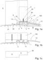
- FIGs 1a to 1c a first embodiment of a threshold 100 not according to the invention is shown.
- the base body 1 is located at least partially on the side facing inwards I.
- an inner leg 13 is provided which can be bent in the direction of the floor B. This is shown in dashed lines and with the reference number 13c.
- the base body 1 there are the grooves 3 and 4 for receiving the magnetic sealing strips 5 and 6.
- the magnetic sealing strips 5 and 6 are attracted by counter magnets 81 in the congruent state, i.e. when the door is closed.
- the door leaf is designated 8 here, while in Figure 1b a frame is shown which is designated 9.
- a first thermal separation 11 thermally separates the base body 1 from the inner area towards the outer area.
- the base body 1 is further formed by the end element 2 facing outwards, which forms the lower end plate.
- This lower end element 2 limits the drainage channel 7, which runs out into the outlet 71 to the outside A.
- An outer leg 14 closes off the floor sill to the outside, while the lower end plate or the lower end element 2 runs out into the extension 21.
- the extension 21 is designed to be wide enough that a frame 9 of the door or window door can be attached there. This is indicated in Figure 1b.
- the frame 9 is attached to the floor sill 100 by means of fastening screws, which are not designated in more detail.
- An adapter 90 which is shown in Figure 1c, is also used for this purpose.
- Figure 1b naturally only shows the outer area, i.e. the area in which the frame 9 is visible.
- the extension 21 or the lower end element 2 has struts 22, which serve to support the extension 21 or the lower end element 2 and which also serve in particular to reduce the heat transfer from the floor sill to the floor B.
- the counter magnets 81 are attached to a carrier which is fastened to the leaf of the door 8 by means of a screw as a fastening means.
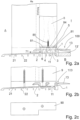
- FIG. 3a and 3b a further embodiment of a threshold 100 not according to the invention is shown. This differs from the previously presented embodiments in that no closing leg is provided on the inward-facing side.
- the level of the inner floor must therefore end at the upper edge of the threshold 100 or the upper edge of the base body 1 in order to ensure a barrier-free transition.
- all other reference numerals are analogous to those in the Figures 1 and 2 presented reference symbols have been used.
- Fig.4 shows a further floor sill 100 not according to the invention.
- the floor sill 100 consists of a base body 1.
- a first thermal separation 11 and a second thermal separation 12 are arranged next to grooves 3, 4 for magnetic sealing strips 5, 6.
- the grooves 3, 4 are connected to a drainage channel 7 which extends along the underside of the base body 1.
- the outlet 71 is arranged on the side of the base body 1 facing outwards A.
- a lower end element 2 is provided on the side facing the floor B.
- This lower end element 2, just like the first and second thermal separations 11, 12, is made of a different material to the base body 1.
- Plastic is preferably used. In order to ensure sufficient stability of the components mentioned, it is of course possible to use appropriately fibre-reinforced plastic.
- An inner leg 13 is provided on the side of the base body 1 facing inwards I.
- An outer leg 14 is arranged on the side facing outwards A.
- the floor threshold 100 which is schematically indicated with an arrow, interacts with a door 8 or a window when used as intended.
- the drawing shows a side view of the door leaf.
- the counter magnets 81 are arranged on the underside of the door leaf in correspondence with the magnetic strips 5, 6, so that when the door 8 is closed, the magnetic strips 5, 6 are pulled upwards.
- Both grooves 3, 4 are, as already mentioned, connected to the drainage channel 7.
- This drainage channel 7 is designed so cleverly that it runs above the end element 2 and is guided over the floor in such a way that it can be easily guided to the outside A.
- the outlet openings of the outlet 71 are offset from inner webs 30, 40.
- This design makes it possible to prevent moisture from being pushed inwards by strong wind or driving rain, for example.
- the outlet to the outside A is not impeded, however.
- a weather leg 80 is provided on the door 8 on the side facing outwards A.
- the weather leg 80 carries an additional seal 82 designed as a hollow profile.
- the weather leg 80 is attached to the door by means of a screw.
- a seal is provided in the upper area of the weather leg 80 in order to prevent moisture from entering there too.
- This can be, for example, a normal silicone joint 83, which is applied before the weather leg is attached. Since the weather leg 80 is designed in two parts, the screw, for example, can be installed in a concealed manner without being affected by moisture later on, thus preventing unsightly rust spots from forming.
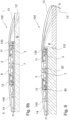
- Fig. 5 shows a variant of the Fig. 4
- the threshold 100 is provided with the inner leg 13, which here has a predetermined bending point 130 at the connection point of the leg 13 with the base body 1.
- This allows the inner leg 13 to be bent into a position 13 1. This takes place in the direction b, i.e. directed towards the floor B, if, for example, the inner floor B is lower than the outer floor B.
- a recess 131 is arranged on the side opposite the predetermined bending point 130. This is rounded, as can be seen, so that bending does not result in such a material change that a break could occur. Furthermore, this recess 131 naturally makes bending in the direction b easier.
- Fig. 6a, 6b and 7 show a further embodiment of the threshold according to the Fig. 4 and 5 , but here with different, i.e. modified, counter magnets 81.
- the counter magnets 81 have a molded pin 842. This serves to attach the counter magnet 81 in the wing of the door 8 or the window. To do this, all that is needed is to drill a corresponding hole in the door 8, to insert the counter magnet 81 with the pin 842.
- the principle works in such a way that the hole is made somewhat narrower than the outer diameter of the pin 842, so that the pin 842 acts like a dowel.
- the pin 842 advantageously has a ribbing or a thread in order to achieve this dowel-like effect.
- Fig. 3b an enlargement of an embodiment of the counter magnet 81 is shown. It can be seen that this counter magnet 81 has a surface F on the side facing the threshold or the magnetic strip 5, 6. This surface F is advantageously concave. Furthermore, this north pole magnetized surface F is preferably provided with a 3-pole design, so that a sequence, for example south pole, north pole, south pole, is provided. This means that the magnetic sealing strips are also securely attracted when the door is closed. This also achieves an extremely favorable sealing effect, since the concave design of the surface F prevents the penetration of wind, moisture and/or heat. Fig.
- FIG. 6a differs from Fig. 7 merely in that the leg 13 pointing inwards I is provided with a corresponding predetermined bending point 130 in order to bring this leg into a lower position 13', which is indicated by dashed lines.
- This leg is fixed, i.e. cannot be changed.
- a threshold 100 according to the invention with bendable inner legs of different lengths.
- the same reference numerals have been used here as have already been described in the previous variants.
- a threshold 100 is shown here which has larger dimensions in terms of width (seen in section) than the previously presented variants. Otherwise, the same reference numerals have been used here as before.
- the door 8 has a recess on the underside into which a support 84 is embedded. This support 84 can be attached to the door 8, for example, using fastening screws.
- This support 84 carries the counter magnets 81.
- a further seal 85 is provided on the side facing inwards I in order to further increase the overall sealing effect.
- a predetermined bending point 140 is provided on the outer leg or its connection to the base body in order to make a compensation here too if necessary. All other reference symbols have already been introduced and are used again here in the same way.
- the Fig. 8a , 8b and 9 differ only in that the leg 13 of the base body 1 pointing inwards I has a different length, so that it can be bent to different depths, as indicated by the dashed position 13 1 of the leg 13.
- the leg 13 pointing inwards is significantly longer than the leg 14 pointing outwards. This allows it to be bent much further, so that height differences of several millimetres, for example 5 to 10 mm, in particular of up to 30 mm, can be compensated.
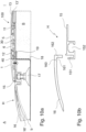
- Fig. 10a shows a threshold 100 not according to the invention with a connecting profile 14 as a height compensation profile H.
- This connecting profile 15 is attached to the underside of the threshold 100. This is done with the usual fastening means, such as at least one screw.
- the connecting profile 15 has an additional leg 16, which is provided here on the side facing outwards A. This additional leg 16 can be bent in the direction b in a position indicated by 161.
- a height adjustment device 17 is provided, which can be fixed in a connecting groove 152.
- the height compensation profile can be fixed using appropriate lock nuts, for example.
- the height compensation profile H is made in two parts, namely with the connecting profile 15 and the additional leg 16, as shown in the Fig.
- a predetermined turning groove 160 with a corresponding and oppositely formed formation 161 is again provided.
- the additional leg 16 can be inserted into a receptacle 151, for example with an angled portion 162. This allows assembly to be carried out in such a way that, for example, the connecting profile 15 is first fastened to the threshold 100, in order to then, when the threshold 100 is also fixed to the floor B, the additional leg 16 can be inserted.
- Such a design is particularly advantageous when larger height differences between outside A and inside I have to be overcome.
- the threshold 100 designed in this way with connecting profile 15 or height compensation profile Hauch helps to create a transition that can essentially also be overcome by disabled vehicles or devices.
- Such a threshold is extremely beneficial to use, particularly in the renovation of old buildings, because such height differences are often found there. Levelling the floors by filling them is usually very laborious and requires appropriate sealing, which often leads to difficulties.
- a height adjustment profile H can help with this. This height adjustment profile H is attached to the side of the threshold facing outwards A, as shown. 100 as well as, in an embodiment not shown, on the side facing inwards I.
- Fig. 10a It is also shown that the inner leg 13 is also designed to be bendable into position 13.
- a seal 18 is attached to the underside of the floor sill 100 or its base body 1 by means of a composite sheet 19.
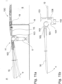
- a further variant of a height compensation profile H is shown, not according to the invention.
- This profile is also characterized by a connecting profile 15, which here, however, has a receptacle 151, which, viewed in section, is circular or designed as a roller pan, in order to receive a correspondingly designed roller 164 of the additional leg 16 or of an intermediate piece 163.
- the height compensation profile H is enlarged and shown as an individual illustration.
- the intermediate piece 163 has an insertion groove 165. This can now accommodate an additional leg 16 formed at the end corresponding to the insertion groove 165. This additional leg 16 can then be kept in a width that is sufficient to overcome a wide variety of widths.
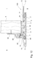
- Fig. 12 another embodiment of the threshold 100 according to the invention is shown.
- the counter magnet 81 is formed in one piece.
- the counter magnet 81 is designed in such a way that its width is exactly above the magnetic sealing strip 5, 6 when the door is closed, in order to then attract both magnets.
- the polarity of the counter magnet 81 is such that it acts exactly like individual counter magnets, so a polarity of south pole, north pole, south pole and south pole, north pole, south pole would be provided here, for example. Otherwise, the polarity shown in Fig. 12
- the embodiment shown is essentially identical to that shown in Fig. 6a variant shown.
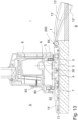
- Fig. 13 shows a further embodiment of the threshold according to the invention with a pivoting device 200 for the inner leg 13.
- the pivoting device is designed as it is, for example, in Fig. 11a or 11b for the connection profile 15.
- the leg has a tubular design on its side facing the threshold 1, which is inserted into a type of ball joint at the inner end of the threshold 1. This allows the inner leg 13 to be easily arranged at the lower floor level on the inside of the threshold 1.
- the thermal separations (not designated here) are also designed differently than in the previous embodiments.
- this variant of a threshold according to the invention represents a further development, in particular of the main subject matter of this patent application.
- IL d can be combined in connection with both the main claim and the subclaims.
- the design is shown here with a window or door profile as a plastic profile.
- an additional seal 84 designed here as a lip seal, is arranged on the side of the door leaf 8 facing the inside. This further improves the tightness of the entire system. This makes installation extremely easy to service, since both lower floor areas and, to a certain extent, higher areas on the inside of the threshold can be easily adjusted.
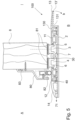
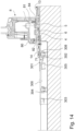
- Fig. 14 shows a threshold not according to the invention with a further connection adapter 301.
- This further connection adapter 301 is arranged on a connection profile 15, wherein the further connection adapter 301 can engage as a clip connection in a recess provided on the connection adapter 308.
- the further connection adapter 301 is designed in such a way that it can accommodate an extension 300.
- a further height adjustment device 304 is provided on the side facing the ground.
- a further interface 303 is also arranged on the outer edge of the extension 300, so that it is possible to connect a further adapter there in order to be able to attach completion elements or extensions there. Otherwise, the embodiment shown here is to be viewed in the same way as the previous figures with regard to the reference symbols, i.e. the same features have been provided with the same reference symbols.
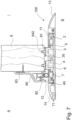
- Fig. 15 shows a non-inventive embodiment of the threshold with a connection adapter 308 and a water drainage channel in front, consisting of a Connection piece 307 and an end-side output piece 309, with a cover grille 308 being provided between these two elements.
- a height adjustment device 17 is arranged below the water drainage channel.
- An insulating layer 500 is provided on the rough side under the floor threshold, which further improves the thermal insulation from the outside to the inside.
- a seal for the outer sealing sheet is also provided here, which is not further designated in this figure. Otherwise, a plastic element is also shown here, which has an additional seal 84 on the rough side. Otherwise, the features in this embodiment have also been designated in the same way as in the previous embodiments of the invention.
- Fig. 16 shows a non-inventive threshold with a connection adapter 308, a widening 300, as in Fig. 14 described and a water drainage channel, as in Fig. 15 described.
- the same reference numerals were used here too. It is clear that the design of the adapter 308 and the widening 300 are cleverly used to allow further elements to be arranged on the widening 300 - for example at the interface 303. This is also done with the clip connection. Above this is a connection profile, whereby this connection profile is designated here with the reference numeral 400. 401 designates a further interface into which a connection profile 402 can be pivoted and then clipped, as can be seen from the dashed lines.
- the base on the output side has the reference numeral 310, all other reference numerals have already been presented in the previous figures.
- Fig. 17 shows a further embodiment according to the invention, which however is almost analogous to the one in Fig. 5 and 6a shown embodiments of the invention.
- the essential difference here is the modified embodiment of the thermal separations 11 and 12 and the design of the profile for the window or modified door element.
- a design of a plastic profile is shown, in which all other elements, as already presented, are also present. A further presentation is therefore dispensed with.
- Fig. 18 shows a variant of the threshold not according to the invention, as shown in Fig. 16 has already been presented. However, here there is no widening between the floor sill 1 and the water drainage channel with cover grille 306 and outer edge 309, but the water drainage channel is attached directly to the adapter 308 and this to the floor sill 1.
- Fig. 19 shows a threshold according to the invention, which is analogous to the one in the Fig. 8b and 8c. However, here a plastic element is provided as a window or door element. The inner edge 13 can be adjusted to the floor level accordingly, as can be seen.
- the Fig. 20 and 21 also show thresholds not according to the invention with a connecting profile, as for example in the Fig. 11a and 11b
- This connection profile has the reference number 15, whereby an outer additional leg 16 is provided, which, as in Fig. 11a or 11b, is arranged in a receptacle designed as a roller pan, for example.
- the inner leg 13 is also designed to be bendable, in the same way as it was already presented in previous figures.
- the difference between Fig. 21 and Fig. 20 is the slightly shorter design of the inner leg 13. Otherwise, a plastic element is also shown here as a door or window element.
- a plastic element is also shown here as a door or window element.
- the floor threshold according to the invention can therefore be used universally for wood, plastic or aluminum profiles.
Landscapes
- Engineering & Computer Science (AREA)
- Civil Engineering (AREA)
- Structural Engineering (AREA)
- Specific Sealing Or Ventilating Devices For Doors And Windows (AREA)
- Door And Window Frames Mounted To Openings (AREA)
Claims (2)
- Seuil sans barrière, en particulier seuil de bâtiment ancien ou de rénovation, qui peut être posé sur un sol fini sans qu'il y ait un retrait du sol, le seuil séparant une zone extérieure d'un bâtiment d'une zone intérieure, ou deux pièces entre elles en coopération avec une fenêtre ou une porte (8), constitué d'un corps de base (1) qui présente deux rainures (3, 4) pour recevoir chacune une bande d'étanchéité magnétique (5, 6), les deux bandes d'étanchéité magnétiques étant disposées l'une à côté de l'autre dans le corps de base (1), vu de l'extérieur vers l'intérieur, une première séparation thermique (11) étant prévue sur le côté du corps de base (1) orienté vers l'intérieur (I) et une deuxième séparation thermique (12) sur le côté du corps de base (1) orienté vers l'extérieur (A), et un élément de fermeture inférieur (2) étant disposé sur le côté du corps de base (1) orienté vers le sol, pour délimiter un canal d'écoulement (7) qui relie les rainures (3, 4) à une sortie (71) prévue sur le côté extérieur du corps de base (1), une branche correspondante (13) avec un point de courbure étant prévue sur au moins un des côtés du seuil de sol (1) pour amener cette branche (13) au niveau du sol respectif.
- Seuil sans barrière, en particulier seuil de bâtiment ancien ou de rénovation, qui peut être posé sur un sol fini sans qu'il y ait un retrait du sol, le seuil isolant une zone extérieure d'un bâtiment d'une zone intérieure ou deux pièces entre elles en coopération avec une fenêtre ou une porte (8), composé d'un corps de base (1) qui présente deux rainures (3, 4) destinées à recevoir chacune une bande d'étanchéité magnétique (5, 6), les deux bandes d'étanchéité magnétiques étant disposées côte à côte dans le corps de base (1), vu de l'extérieur vers l'intérieur, une première séparation thermique (11) étant prévue sur le côté du corps de base (1) orienté vers l'intérieur (I) et une deuxième séparation thermique (12) sur le côté du corps de base (1) orienté vers l'extérieur (A), et un élément de fermeture inférieur (2) étant disposé sur le côté du corps de base (1) orienté vers le sol, afin de délimiter un canal d'écoulement (7), qui relie les rainures (3, 4) à une sortie (71) prévue sur le côté extérieur du corps de base (1), une branche (13) et/ou un profilé de raccordement (15) étant relié(e) au seuil de sol (1) par un dispositif de pivotement (200) afin d'amener cette branche (13) et/ou le profilé de raccordement (15) au niveau du sol concerné.
Applications Claiming Priority (4)
| Application Number | Priority Date | Filing Date | Title |
|---|---|---|---|
| US13/365,283 US20130199101A1 (en) | 2012-02-03 | 2012-02-03 | Barrier-free floor threshold, in particular old building or renovation threshold |
| DE201220001082 DE202012001082U1 (de) | 2012-02-03 | 2012-02-03 | Barrierefreie Bodenschwelle, insbesondere Altbau- bzw. Renovierungsschwelle |
| US13/531,222 US20130199102A1 (en) | 2012-02-03 | 2012-06-22 | Barrier-free floor threshold, in particular old building or renovation threshold |
| PCT/EP2013/052105 WO2013113914A2 (fr) | 2012-02-03 | 2013-02-01 | Seuil accessible aux handicapés, en particulier seuil d'une construction ancienne ou d'un logement rénové |
Publications (3)
| Publication Number | Publication Date |
|---|---|
| EP2809864A2 EP2809864A2 (fr) | 2014-12-10 |
| EP2809864C0 EP2809864C0 (fr) | 2024-12-04 |
| EP2809864B1 true EP2809864B1 (fr) | 2024-12-04 |
Family
ID=47749770
Family Applications (1)
| Application Number | Title | Priority Date | Filing Date |
|---|---|---|---|
| EP13705934.1A Active EP2809864B1 (fr) | 2012-02-03 | 2013-02-01 | Seuil accessible aux handicapés, en particulier seuil d'une construction ancienne ou d'un logement rénové |
Country Status (3)
| Country | Link |
|---|---|
| EP (1) | EP2809864B1 (fr) |
| JP (1) | JP2015510057A (fr) |
| WO (1) | WO2013113914A2 (fr) |
Families Citing this family (8)
| Publication number | Priority date | Publication date | Assignee | Title |
|---|---|---|---|---|
| DE102015100266A1 (de) | 2015-01-09 | 2016-07-14 | Heroal - Johann Henkenjohann Gmbh & Co. Kg | Drainagesystem für Tür- und Fensterelemente |
| CN104806135A (zh) * | 2015-03-13 | 2015-07-29 | 肖正权 | 木质门窗、线条底部防水技术 |
| EP3396098B1 (fr) * | 2017-04-24 | 2020-01-29 | SFS Group AG | Élément de retenue pour rejet d'eau et son utilisation |
| JP6991099B2 (ja) * | 2018-05-11 | 2022-01-12 | 三菱電機株式会社 | 乗場敷居の位置調整構造 |
| US11174673B2 (en) | 2019-05-24 | 2021-11-16 | Nana Wall Systems, Inc. | Threshold sill with removable barrier insert |
| DE102022115905A1 (de) | 2022-03-31 | 2023-10-05 | ALUMAT Frey GmbH | Bodenschwelle |
| EP4253709A1 (fr) | 2022-03-31 | 2023-10-04 | ALUMAT Frey GmbH | Seuil de porte |
| CN118462033A (zh) * | 2024-04-30 | 2024-08-09 | 米亚门窗系统(江苏)有限公司 | 一种磁吸式防风防水门及其组装方法 |
Family Cites Families (9)
| Publication number | Priority date | Publication date | Assignee | Title |
|---|---|---|---|---|
| US2273877A (en) * | 1939-05-04 | 1942-02-24 | Fred W Kammerer | Door saddle |
| DE8810035U1 (de) * | 1988-08-05 | 1988-10-27 | Frey, Harry, 8950 Kaufbeuren | Magnetabdichtung für Türen |
| DE102005035220A1 (de) * | 2004-08-10 | 2006-06-01 | Inge Frey | Schiebeelement |
| DE102005030462A1 (de) * | 2005-06-28 | 2007-01-04 | Inge Frey | Bodenschwelle |
| JP4788266B2 (ja) * | 2005-09-27 | 2011-10-05 | パナソニック電工株式会社 | 引戸枠 |
| DE102006007742A1 (de) * | 2006-01-13 | 2007-07-19 | Inge Frey | Bodenschwelle |
| DE102007003904B4 (de) * | 2007-01-19 | 2017-03-02 | Inge Frey | Bodenschwelle und Schiebetüre mit einer Bodenschwelle |
| DE102009056118A1 (de) * | 2009-11-30 | 2011-06-01 | Inge Frey | Dichtung, insbesondere für Schiebetüren |
| DE202010004020U1 (de) * | 2010-03-22 | 2011-07-27 | Inge Frey | Bodenschwelle |
-
2013
- 2013-02-01 JP JP2014556016A patent/JP2015510057A/ja active Pending
- 2013-02-01 EP EP13705934.1A patent/EP2809864B1/fr active Active
- 2013-02-01 WO PCT/EP2013/052105 patent/WO2013113914A2/fr not_active Ceased
Also Published As
| Publication number | Publication date |
|---|---|
| EP2809864C0 (fr) | 2024-12-04 |
| WO2013113914A2 (fr) | 2013-08-08 |
| WO2013113914A3 (fr) | 2013-10-24 |
| JP2015510057A (ja) | 2015-04-02 |
| EP2809864A2 (fr) | 2014-12-10 |
Similar Documents
| Publication | Publication Date | Title |
|---|---|---|
| EP2809864B1 (fr) | Seuil accessible aux handicapés, en particulier seuil d'une construction ancienne ou d'un logement rénové | |
| EP2055882A2 (fr) | Cadre de porte doté d'un seuil | |
| EP3259428B1 (fr) | Dispositif d'étanchéité pour éléments de fenêtre et éléments de porte | |
| EP2327854A2 (fr) | Seuil de sol et système d'élargissement et/ou d'isolation | |
| WO2014167077A1 (fr) | Seuil en particulier pour passages sans obstacle | |
| EP3043017B2 (fr) | Systeme de drainage pour des elements de porte et de fenetre | |
| EP2434082B1 (fr) | Panneau de rebord de fenêtre | |
| AT515020B1 (de) | Fensterbank-Anschlusseinheit | |
| DE29708214U1 (de) | Türrahmen | |
| DE102006007742A1 (de) | Bodenschwelle | |
| DE202012001082U9 (de) | Barrierefreie Bodenschwelle, insbesondere Altbau- bzw. Renovierungsschwelle | |
| EP2395196B1 (fr) | Porte additionelle, notamment porte moustiquaire, avec un palier à rouleaux réglable en hauteur | |
| AT10536U1 (de) | Rollladenkasten | |
| WO2011067210A2 (fr) | Paroi coulissante comportant au moins deux vantaux | |
| DE102016104583A1 (de) | Profilsystem für Flügelelemente von Fassaden | |
| DE202007003256U1 (de) | Duschabtrennung | |
| AT12925U1 (de) | Zusatzelement zum Anordnen an einer Bodenschwelle | |
| WO2010006626A1 (fr) | Baguette de couverture | |
| EP2182157B1 (fr) | Ecran pour un espace entre un dormant de porte ou de portail et intrados | |
| AT510161B1 (de) | Vorrichtung zur verbindung von wandteilen | |
| DE20306546U1 (de) | Türdichtungsschwelle | |
| DE202008014802U1 (de) | Rahmen für ein Fenster oder eine Tür | |
| DE29518751U1 (de) | Flächenelement, insbesondere Fassadenelement | |
| DE10321685B4 (de) | Tür-oder Fensterflügel mit einer Isolierverglasung | |
| DE202005020242U1 (de) | Bodenschwelle |
Legal Events
| Date | Code | Title | Description |
|---|---|---|---|
| PUAI | Public reference made under article 153(3) epc to a published international application that has entered the european phase |
Free format text: ORIGINAL CODE: 0009012 |
|
| 17P | Request for examination filed |
Effective date: 20140903 |
|
| AK | Designated contracting states |
Kind code of ref document: A2 Designated state(s): AL AT BE BG CH CY CZ DE DK EE ES FI FR GB GR HR HU IE IS IT LI LT LU LV MC MK MT NL NO PL PT RO RS SE SI SK SM TR |
|
| AX | Request for extension of the european patent |
Extension state: BA ME |
|
| DAX | Request for extension of the european patent (deleted) | ||
| 17Q | First examination report despatched |
Effective date: 20160714 |
|
| STAA | Information on the status of an ep patent application or granted ep patent |
Free format text: STATUS: EXAMINATION IS IN PROGRESS |
|
| GRAP | Despatch of communication of intention to grant a patent |
Free format text: ORIGINAL CODE: EPIDOSNIGR1 |
|
| STAA | Information on the status of an ep patent application or granted ep patent |
Free format text: STATUS: GRANT OF PATENT IS INTENDED |
|
| INTG | Intention to grant announced |
Effective date: 20240628 |
|
| GRAS | Grant fee paid |
Free format text: ORIGINAL CODE: EPIDOSNIGR3 |
|
| GRAA | (expected) grant |
Free format text: ORIGINAL CODE: 0009210 |
|
| STAA | Information on the status of an ep patent application or granted ep patent |
Free format text: STATUS: THE PATENT HAS BEEN GRANTED |
|
| AK | Designated contracting states |
Kind code of ref document: B1 Designated state(s): AL AT BE BG CH CY CZ DE DK EE ES FI FR GB GR HR HU IE IS IT LI LT LU LV MC MK MT NL NO PL PT RO RS SE SI SK SM TR |
|
| REG | Reference to a national code |
Ref country code: GB Ref legal event code: FG4D Free format text: NOT ENGLISH |
|
| REG | Reference to a national code |
Ref country code: CH Ref legal event code: EP |
|
| REG | Reference to a national code |
Ref country code: DE Ref legal event code: R096 Ref document number: 502013016556 Country of ref document: DE |
|
| REG | Reference to a national code |
Ref country code: IE Ref legal event code: FG4D Free format text: LANGUAGE OF EP DOCUMENT: GERMAN |
|
| U01 | Request for unitary effect filed |
Effective date: 20241217 |
|
| U07 | Unitary effect registered |
Designated state(s): AT BE BG DE DK EE FI FR IT LT LU LV MT NL PT RO SE SI Effective date: 20250127 |
|
| U20 | Renewal fee for the european patent with unitary effect paid |
Year of fee payment: 13 Effective date: 20250221 |
|
| PG25 | Lapsed in a contracting state [announced via postgrant information from national office to epo] |
Ref country code: HR Free format text: LAPSE BECAUSE OF FAILURE TO SUBMIT A TRANSLATION OF THE DESCRIPTION OR TO PAY THE FEE WITHIN THE PRESCRIBED TIME-LIMIT Effective date: 20241204 |
|
| PG25 | Lapsed in a contracting state [announced via postgrant information from national office to epo] |
Ref country code: ES Free format text: LAPSE BECAUSE OF FAILURE TO SUBMIT A TRANSLATION OF THE DESCRIPTION OR TO PAY THE FEE WITHIN THE PRESCRIBED TIME-LIMIT Effective date: 20241204 |
|
| PG25 | Lapsed in a contracting state [announced via postgrant information from national office to epo] |
Ref country code: NO Free format text: LAPSE BECAUSE OF FAILURE TO SUBMIT A TRANSLATION OF THE DESCRIPTION OR TO PAY THE FEE WITHIN THE PRESCRIBED TIME-LIMIT Effective date: 20250304 |
|
| PG25 | Lapsed in a contracting state [announced via postgrant information from national office to epo] |
Ref country code: GR Free format text: LAPSE BECAUSE OF FAILURE TO SUBMIT A TRANSLATION OF THE DESCRIPTION OR TO PAY THE FEE WITHIN THE PRESCRIBED TIME-LIMIT Effective date: 20250305 |
|
| PG25 | Lapsed in a contracting state [announced via postgrant information from national office to epo] |
Ref country code: RS Free format text: LAPSE BECAUSE OF FAILURE TO SUBMIT A TRANSLATION OF THE DESCRIPTION OR TO PAY THE FEE WITHIN THE PRESCRIBED TIME-LIMIT Effective date: 20250304 |
|
| PG25 | Lapsed in a contracting state [announced via postgrant information from national office to epo] |
Ref country code: SM Free format text: LAPSE BECAUSE OF FAILURE TO SUBMIT A TRANSLATION OF THE DESCRIPTION OR TO PAY THE FEE WITHIN THE PRESCRIBED TIME-LIMIT Effective date: 20241204 |
|
| PG25 | Lapsed in a contracting state [announced via postgrant information from national office to epo] |
Ref country code: PL Free format text: LAPSE BECAUSE OF FAILURE TO SUBMIT A TRANSLATION OF THE DESCRIPTION OR TO PAY THE FEE WITHIN THE PRESCRIBED TIME-LIMIT Effective date: 20241204 |
|
| PG25 | Lapsed in a contracting state [announced via postgrant information from national office to epo] |
Ref country code: IS Free format text: LAPSE BECAUSE OF FAILURE TO SUBMIT A TRANSLATION OF THE DESCRIPTION OR TO PAY THE FEE WITHIN THE PRESCRIBED TIME-LIMIT Effective date: 20250404 |
|
| PG25 | Lapsed in a contracting state [announced via postgrant information from national office to epo] |
Ref country code: SK Free format text: LAPSE BECAUSE OF FAILURE TO SUBMIT A TRANSLATION OF THE DESCRIPTION OR TO PAY THE FEE WITHIN THE PRESCRIBED TIME-LIMIT Effective date: 20241204 |
|
| PG25 | Lapsed in a contracting state [announced via postgrant information from national office to epo] |
Ref country code: CZ Free format text: LAPSE BECAUSE OF FAILURE TO SUBMIT A TRANSLATION OF THE DESCRIPTION OR TO PAY THE FEE WITHIN THE PRESCRIBED TIME-LIMIT Effective date: 20241204 |
|
| PG25 | Lapsed in a contracting state [announced via postgrant information from national office to epo] |
Ref country code: MC Free format text: LAPSE BECAUSE OF FAILURE TO SUBMIT A TRANSLATION OF THE DESCRIPTION OR TO PAY THE FEE WITHIN THE PRESCRIBED TIME-LIMIT Effective date: 20241204 |
|
| REG | Reference to a national code |
Ref country code: CH Ref legal event code: PL |
|
| PLBE | No opposition filed within time limit |
Free format text: ORIGINAL CODE: 0009261 |
|
| STAA | Information on the status of an ep patent application or granted ep patent |
Free format text: STATUS: NO OPPOSITION FILED WITHIN TIME LIMIT |
|
| PG25 | Lapsed in a contracting state [announced via postgrant information from national office to epo] |
Ref country code: CH Free format text: LAPSE BECAUSE OF NON-PAYMENT OF DUE FEES Effective date: 20250228 |
|
| 26N | No opposition filed |
Effective date: 20250905 |
|
| GBPC | Gb: european patent ceased through non-payment of renewal fee |
Effective date: 20250304 |
|
| PG25 | Lapsed in a contracting state [announced via postgrant information from national office to epo] |
Ref country code: GB Free format text: LAPSE BECAUSE OF NON-PAYMENT OF DUE FEES Effective date: 20250304 |
|
| PG25 | Lapsed in a contracting state [announced via postgrant information from national office to epo] |
Ref country code: IE Free format text: LAPSE BECAUSE OF NON-PAYMENT OF DUE FEES Effective date: 20250201 |
|
| U20 | Renewal fee for the european patent with unitary effect paid |
Year of fee payment: 14 Effective date: 20260225 |