EP2806538B1 - Verfahren zur herstellung eines rotors für einen permanentmagnetmotor - Google Patents
Verfahren zur herstellung eines rotors für einen permanentmagnetmotor Download PDFInfo
- Publication number
- EP2806538B1 EP2806538B1 EP12866347.3A EP12866347A EP2806538B1 EP 2806538 B1 EP2806538 B1 EP 2806538B1 EP 12866347 A EP12866347 A EP 12866347A EP 2806538 B1 EP2806538 B1 EP 2806538B1
- Authority
- EP
- European Patent Office
- Prior art keywords
- rotor
- permanent
- magnet
- pole
- hole
- Prior art date
- Legal status (The legal status is an assumption and is not a legal conclusion. Google has not performed a legal analysis and makes no representation as to the accuracy of the status listed.)
- Active
Links
- 238000004519 manufacturing process Methods 0.000 title claims description 25
- 238000000034 method Methods 0.000 title claims description 18
- 125000006850 spacer group Chemical group 0.000 claims description 108
- XEEYBQQBJWHFJM-UHFFFAOYSA-N Iron Chemical group [Fe] XEEYBQQBJWHFJM-UHFFFAOYSA-N 0.000 claims description 61
- 230000005291 magnetic effect Effects 0.000 claims description 60
- 230000035515 penetration Effects 0.000 claims description 16
- 238000003475 lamination Methods 0.000 claims description 10
- 230000007704 transition Effects 0.000 claims description 6
- 238000004458 analytical method Methods 0.000 claims description 4
- 239000000696 magnetic material Substances 0.000 claims description 4
- PMVSDNDAUGGCCE-TYYBGVCCSA-L Ferrous fumarate Chemical group [Fe+2].[O-]C(=O)\C=C\C([O-])=O PMVSDNDAUGGCCE-TYYBGVCCSA-L 0.000 claims description 2
- 238000005520 cutting process Methods 0.000 claims description 2
- 238000001125 extrusion Methods 0.000 claims description 2
- 239000003302 ferromagnetic material Substances 0.000 claims description 2
- 238000010586 diagram Methods 0.000 description 15
- 230000004907 flux Effects 0.000 description 8
- 239000000463 material Substances 0.000 description 8
- 239000003292 glue Substances 0.000 description 7
- 229910052751 metal Inorganic materials 0.000 description 7
- 239000002184 metal Substances 0.000 description 7
- 238000005452 bending Methods 0.000 description 3
- 238000004891 communication Methods 0.000 description 3
- 238000009434 installation Methods 0.000 description 3
- 238000004804 winding Methods 0.000 description 3
- 229910000963 austenitic stainless steel Inorganic materials 0.000 description 2
- 230000004323 axial length Effects 0.000 description 2
- 238000006243 chemical reaction Methods 0.000 description 2
- 230000000694 effects Effects 0.000 description 2
- 239000003822 epoxy resin Substances 0.000 description 2
- 239000011152 fibreglass Substances 0.000 description 2
- 238000002955 isolation Methods 0.000 description 2
- 230000005415 magnetization Effects 0.000 description 2
- 230000035699 permeability Effects 0.000 description 2
- 229920000647 polyepoxide Polymers 0.000 description 2
- 229910052761 rare earth metal Inorganic materials 0.000 description 2
- 150000002910 rare earth metals Chemical class 0.000 description 2
- 230000001105 regulatory effect Effects 0.000 description 2
- 238000000926 separation method Methods 0.000 description 2
- 229920001187 thermosetting polymer Polymers 0.000 description 2
- 239000004634 thermosetting polymer Substances 0.000 description 2
- 229910000838 Al alloy Inorganic materials 0.000 description 1
- 229920000049 Carbon (fiber) Polymers 0.000 description 1
- 229910000976 Electrical steel Inorganic materials 0.000 description 1
- 229910001069 Ti alloy Inorganic materials 0.000 description 1
- 238000012271 agricultural production Methods 0.000 description 1
- 229910000828 alnico Inorganic materials 0.000 description 1
- 239000004917 carbon fiber Substances 0.000 description 1
- 239000000919 ceramic Substances 0.000 description 1
- 238000011217 control strategy Methods 0.000 description 1
- 230000007547 defect Effects 0.000 description 1
- 230000007123 defense Effects 0.000 description 1
- 230000001419 dependent effect Effects 0.000 description 1
- 238000011161 development Methods 0.000 description 1
- 230000018109 developmental process Effects 0.000 description 1
- 238000005516 engineering process Methods 0.000 description 1
- 230000006872 improvement Effects 0.000 description 1
- 238000009776 industrial production Methods 0.000 description 1
- VNWKTOKETHGBQD-UHFFFAOYSA-N methane Chemical compound C VNWKTOKETHGBQD-UHFFFAOYSA-N 0.000 description 1
- 230000004048 modification Effects 0.000 description 1
- 238000012986 modification Methods 0.000 description 1
- 229910001172 neodymium magnet Inorganic materials 0.000 description 1
- 238000012827 research and development Methods 0.000 description 1
- 230000001360 synchronised effect Effects 0.000 description 1
- 229910000859 α-Fe Inorganic materials 0.000 description 1
Images


Classifications
-
- H—ELECTRICITY
- H02—GENERATION; CONVERSION OR DISTRIBUTION OF ELECTRIC POWER
- H02K—DYNAMO-ELECTRIC MACHINES
- H02K15/00—Methods or apparatus specially adapted for manufacturing, assembling, maintaining or repairing of dynamo-electric machines
- H02K15/02—Methods or apparatus specially adapted for manufacturing, assembling, maintaining or repairing of dynamo-electric machines of stator or rotor bodies
- H02K15/03—Methods or apparatus specially adapted for manufacturing, assembling, maintaining or repairing of dynamo-electric machines of stator or rotor bodies having permanent magnets
-
- H—ELECTRICITY
- H02—GENERATION; CONVERSION OR DISTRIBUTION OF ELECTRIC POWER
- H02K—DYNAMO-ELECTRIC MACHINES
- H02K1/00—Details of the magnetic circuit
- H02K1/06—Details of the magnetic circuit characterised by the shape, form or construction
- H02K1/22—Rotating parts of the magnetic circuit
- H02K1/27—Rotor cores with permanent magnets
- H02K1/2706—Inner rotors
- H02K1/272—Inner rotors the magnetisation axis of the magnets being perpendicular to the rotor axis
- H02K1/274—Inner rotors the magnetisation axis of the magnets being perpendicular to the rotor axis the rotor consisting of two or more circumferentially positioned magnets
- H02K1/2753—Inner rotors the magnetisation axis of the magnets being perpendicular to the rotor axis the rotor consisting of two or more circumferentially positioned magnets the rotor consisting of magnets or groups of magnets arranged with alternating polarity
- H02K1/276—Magnets embedded in the magnetic core, e.g. interior permanent magnets [IPM]
-
- Y—GENERAL TAGGING OF NEW TECHNOLOGICAL DEVELOPMENTS; GENERAL TAGGING OF CROSS-SECTIONAL TECHNOLOGIES SPANNING OVER SEVERAL SECTIONS OF THE IPC; TECHNICAL SUBJECTS COVERED BY FORMER USPC CROSS-REFERENCE ART COLLECTIONS [XRACs] AND DIGESTS
- Y10—TECHNICAL SUBJECTS COVERED BY FORMER USPC
- Y10T—TECHNICAL SUBJECTS COVERED BY FORMER US CLASSIFICATION
- Y10T29/00—Metal working
- Y10T29/49—Method of mechanical manufacture
- Y10T29/49002—Electrical device making
- Y10T29/49009—Dynamoelectric machine
- Y10T29/49012—Rotor
Definitions
- the invention relates to a method for manufacturing a permanent-magnet motor rotor.
- a motor is an electromagnetic device taking magnetic field as media to carry out mutual conversion between mechanical energy and electrical energy.
- a motor winding is energized to generate a magnetic field, such as a conventional DC motor, the motor and so on.
- This electrically excited motor not only needs a special winding and a corresponding device but also needs to be continuously provided with energy to maintain its current flow.
- the magnetic field is generated by a permanent magnet. Due to the inherent characteristics of a permanent-magnet material, after it is pre-magnetized (magnetization), it does not need external energy to establish the magnetic field around its surrounding space; that is, it is the so-called permanent magnet motor.
- the permanent magnet motor Compared with the conventional excited motor, the permanent magnet motor has the advantages of simple structure, low loss, high power factor, high efficiency, high power density, high starting torque, low temperature, light weight and other obvious characteristics. With the continuous improvement and perfection of the magnetic properties in rare-earth permanent-magnet materials (especially NdFeB) and gradually reduced price, the permanent-magnet motor research and development gradually becomes mature, thus facilitating the permanent magnet motor to be more and more widely used in defense, industrial and agricultural production, daily life and so on.
- rare-earth permanent-magnet materials especially NdFeB
- the permanent-magnet motor is the motor which depends on the permanent magnet on a rotor to generate the magnet field.
- Its stator structure is basically identical to that of a common synchronous / asynchronous motor. That is, it consists of a stator iron core constituted by stacked silicon steel sheets and a stator coil embedded in an iron-core slot of the stator. It is energized by three-phase alternating current to generate a rotating magnetic field in the stator coil.
- the permanent-magnet motor rotor mainly consists of a rotor iron core and the permanent magnet, which is the main difference between the permanent-magnet motor and other type of the motor.
- a rotor magnetic circuit structure is the key technology of the permanent magnet motor. If a magnetic path structure adopted by the rotor is different, the operating performance, the control strategy, the manufacturing process and the use occasion of the motor are also different.
- the rotor magnetic path of the permanent-magnet motor may generally be divided into three types including a surface type, a built-in type and a claw-pole type.
- the surface-type rotor magnetic path has the advantages of simple structure and low manufacturing cost.
- this type permanent-magnet motor does not have asynchronous starting capability.
- the rotor has worse mechanical strength, and the permanent magnet is easily broken at high rotation speed.
- the permanent magnet of the built-in type permanent-magnet motor rotor is positioned inside the rotor.
- the magnetic path structure of the built-in type rotor can also be divided into three types including a radial type, a tangential type and a mixed type.
- the built-in permanent-magnet motor rotor may protect the permanent magnet with the lower mechanical properties.
- the size of the permanent magnet may be tremendously increased. Therefore, the structure of the permanent-magnet motor rotor is currently widely used.
- the conventional permanent-magnet motor rotor generally adopts a rotor guide strip to fasten the rotor.
- problems of low mechanical strength, poor reliability, severe eddy current loss of the rotor surface, obvious magnetic flux leakage, etc. These hinder the development of the permanent-magnet motor with high power, high speed and large rotary diameter, and furthermore limit the application of the permanent-magnet motor on high-speed trains as a traction motor.
- China patent application No. 201010513307.3 discloses a big-power permanent-magnet motor rotor and a method for mounting the rotor.
- the rotor Adopting a permanent-magnet embedded structure, the rotor consists of at least two rotor units along the axial direction. A magnet-separation groove along the rotor in the axial direction is opened and provided on an iron core between two adjacent permanent magnets of each rotor unit. A spacer made of a non-magnetic material is provided between the adjacent rotor units. An end plate is provided at two ends of the rotor unit. At least two rotor units are fixed through axially positioned tightening bolt.
- the permanent-magnet rotor has the following disadvantages: 1.
- the centrifugal force stressed by a rotor pole shoe is born jointly by an end plate, the spacer and a positioning tightening bolt. That is, the positioning tightening bolt fixing the rotor unit needs to bear bending moment.
- the centrifugal force is so large that the positioning tightening bolt is easily to be bended by the centrifugal force. That is, the rotor does not apply to the motor with high speed rotation.2.
- the magnet-separation groove is opened and provided at the iron core, the iron core, between the adjacent permanent magnet, still has a connection part.
- the magnetic field of the permanent magnet of adjacent poles through the direct communication of the iron core between the permanent magnets, causes magnetic flux leakage. That is, the structure cannot avoid magnetic flux leakage and has serious magnetic flux leakage. 3.
- the spacer is provided between two adjacent rotor units. The thickness of the spacer occupies the effective length of the rotor in the axial direction. When the number of the rotor units of the adopted rotor is increased and the thickness of the rotor spacer is increased, the effective length is dramatically reduced, thus affecting the electromagnetic properties of the rotor.
- JP2004-229442A discloses a method of manufacturing a laminated core in which a laminated body of segment pieces can be laminated without causing a positional shift, and furthermore a slit piece can be easily removed after lamination.
- the invention provides a method for manufacturing a permanent-magnet motor rotor, which may manufacture a motor with high mechanical strength and applicable for high-speed rotation.
- the present invention provides a method for manufacturing a permanent-magnet motor rotor as described in the claim 1, as well as some advantageous embodiments as described in the dependent claims.
- the lightening hole is a circular hole, a kidney-shaped hole, or a polygonal hole with arc transition at its comer; and the lightening hole is mainly concentrated at the comer of the permanent-body through hole.
- Step 4) the upper end surface of the permanent magnet and the lower end surface of the rotor pole shoe are fitted; there is a metal glue between the permanent magnet and the rotor pole shoe; the lower surface of the permanent magnet and the rotor iron core are fitted; and there is the metal glue between the permanent magnet and the rotor iron core.
- Step 5 a lock washer is placed between the nut of an iron-core tightening bolt and the rotor iron core to prevent the nut of the iron-core tightening bolt from becoming loosed; or the thread fitting between the iron-core tightening bolt and the nut is coated therein with the metal glue to realize the tight connection between the iron-core tightening bolt and the nut;
- Step 7) when the front end cover and the rear end cover are installed, two ends of each pole-shoe tightening bolt are opened and provided with a mounting bolt hole; the front end cover and the rear end cover are respectively provided thereon with a fixing bolt hole aligning with the pole-shoe tightening bolt one by one; the fixing bolt hole is aligned to a mounting bolt hole; and the bolt is inserted into the mounting bolt hole and fastened, thus completing the installation of the front end cover and the rear end cover.
- Step 7) after the front end cover and the rear end cover are installed, the gap between the rotor pole shoe and the rotor spacers is filled with a thermosetting polymer material, such as glass fiber reinforced plastics, epoxy resin, and so on.
- a thermosetting polymer material such as glass fiber reinforced plastics, epoxy resin, and so on.
- the invention has the following conception: the rotor spacer divides a rotor structure into multiple rotor units in the axially direction of the rotor structure; magnetic isolation is carried out for the rotor pole shoe of the adjacent rotor units through the rotor spacer.
- the rotor pole shoes are independent with each other and may not be in mutual communication, thus avoiding the magnetic flux leakage phenomenon.
- the rotor structure is close to the pole-shoe tightening bolt and the iron-core tightening bolt to be tightened tightly.
- Two ends of the rotor pole shoe closely stand against two rotor spacers, respectively.
- the centrifugal force, stressing on the rotor pole shoe and the permanent magnet when the rotor structure rotates is resisted by the friction between the rotor pole shoe and the rotor spacer.
- Two end surfaces of the rotor iron core closely stand against two the rotor spacers, respectively.
- the centrifugal force, stressing on the rotor pole shoe and the permanent magnet when the rotor structure rotates is resisted by the friction between the rotor iron core and the rotor spacer.
- the centrifugal force is also resisted by the mutual friction between the laminations of the rotor iron core, between the laminations of the rotor pole shoe and between the laminations of the rotor spacer.
- the friction between the rotor pole shoe and the rotor spacer is regulated based on the regulation of the tightening force of the pole-shoe tightening bolt.
- the pole-shoe tightening bolt only needs to bear the axial tensile force and does not need to bear the bending moment generated by the centrifugal force.
- the pole-shoe tightening bolt is not easy to be broken, and the rotor structure hence has long service life.
- the invention has the following effects: 1.
- the centrifugal force, generated when the rotor structure rotates, is resisted by the friction between the rotor pole shoe and the spacer.
- the tightening bolt is not easy to be bended and broken.
- the rotor structure has a long service life.
- the permanent magnet and the rotor iron core pass through the rotor spacer respectively. That is, the thickness of the rotor spacer does not occupy the axial length of the rotor structure.
- the rotor pole shoes are independent with each other, thus avoiding magnetic flux leakage phenomenon.
- a method for manufacturing a permanent-magnet motor rotor wherein the permanent-magnet motor rotor comprises a front end at a first axial end of the rotor and a rear end at the end of said rotor axially opposite to the first axial end, includes the following steps:
- thermosetting polymer material such as glass fiber reinforced plastics, epoxy resin, and so on.
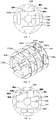
- the magnetic yoke unit A is made of a ferromagnetic material plate with good magnetic property.
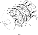
- a flat key 25 is provided on the rotary shaft 10.
- the rotor spacer 16 and the rotor iron core 15 are provided thereon with a rotary-shaft through hole allowing for penetration by the rotary shaft and a key slot matched with the flat key.
- the flat key 25 is matched with the key slot to realize the circumferential positioning of the rotary shaft as well as the rotor iron core 15 and the rotor spacer 16.
- a shaft ring 102 is provided on the rotary shaft 10 to realize the circumferential positioning of the rotor iron core 15 and the rotor spacer 16 which are relative to the rotary shaft.
- the permanent magnet 13 between the rotor pole shoe 14 and the rotor iron core 15 s a single-block magnet. Or multiple permanent magnets 13 between the rotor pole shoe 14 and the rotor iron core 15 are jointed along the rotor axially to form a permanent magnet group.
- the permanent-magnet through hole 165 on the rotor spacer 16 aligns with the permanent magnet 13 one by one.
- a placing strip is provided between the adjacent permanent-magnet through holes 165.
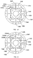
- the first rotor spacer 16a When the permanent magnet 13 is a single-block magnet, the first rotor spacer 16a is adopted.
- the structure of the first rotor spacer 16a is showed in Fig. 7 .
- the rotor spacer 16a, used for accommodating the through hole 165 of the permanent magnet 13, is an irregularly shaped hole constitution.
- the permanent magnet between the rotor pole shoe and the rotor iron core is a single-block magnet.
- the inner sides 163a and 164a of the permanent-magnet through hole 161 of the rotor spacer 16a are respectively and mutually close to and lean against the surfaces 133a and 131a of the permanent magnet 13a, thus realizing the radial positioning of the permanent magnet 13a relative to the rotor shaft 10.
- the inner sides 161a and 162a of the rotor spacer 16a are respectively and mutually close to and lean against two sides 132a of the permanent magnet 13a, thus realizing the circumferential positioning of the permanent magnet 13a relative to the rotor shaft 10, as shown in Fig. 8 .
- the second rotor spacer 16ba is adopted.
- the structure of the second rotor spacer is shown in Fig. 9 .
- Two permanent magnets between the rotor pole shoe and the rotor iron core are jointed axially along the rotor.
- the inner sides 163b and 164b of the rotor spacer 16b are used for realizing the radial positioning of the permanent magnet 13 relative to the rotor shaft 10.
- the inner sides 162b and 165b are used for realizing the circumferential positioning of the permanent magnet 13 relative to the rotor shaft 10.
- the key slot 164 and an inner circular hole 163 are used for realizing the circumferential and radial positioning of the rotor spacer 16b relative to the rotor shaft 10.
- One side of the through hole used for accommodating the permanent magnet 13 adopts two circular arcs 161b, and the other side thereof adopts a straight side 165b.
- the analysis of the 2D magnetic path of the permanent-magnet motor rotor is shown as Fig. 2 .
- the magnetic flow (magnetic line) of the magnetic field of the motor circulates based on the following paths:
- the magnetic line starts from current permanent magnet 13A, passes through the rotor pole shoe 14A, enters into a gas gap 28, passes through a stator tooth part 262, enters into a stator, reaches the area corresponding to adjacent poles in the stator along a yoke part 261 of the stator, enters into the gas gap through a tooth part of a stator, enters into the S pole of the adjacent permanent magnet through the adjacent rotor pole shoe 14B, enters into the rotor iron core 15 from the N pole, finally goes back to the N pole of the current permanent magnet 13 A, and forms a circuit of the magnetic line.
- the invention has the following conception:
- the rotor spacer 16 divides a rotor structure into multiple rotor units in the axially direction of the rotor structure. Magnetic isolation is carried out for the rotor pole shoe 14 of the adjacent rotor units through the rotor spacer 16. In the same rotor unit, the rotor pole shoes 14 are independent with each other and may not be in mutual communication, thus avoiding the magnetic flux leakage phenomenon.
- the rotor structure is close to the pole-shoe tightening bolt 23 and the iron-core tightening bolt 24 to be tightened tightly.
- Two ends of the rotor pole shoe 14 closely stand against two rotor spacers 16, respectively.
- the centrifugal force, stressing on the rotor pole shoe 14 and the permanent magnet 13 when the rotor structure rotates, is resisted based on the friction between the rotor pole shoe 14 and the rotor spacer 16.
- Two end surfaces of the rotor iron core 15 closely stand against two the rotor spacers 16, respectively.
- the centrifugal force, stressing on the rotor pole shoe and the permanent magnet when the rotor structure rotates is resisted by the friction between the rotor iron core 15 and the rotor spacer 16.
- the centrifugal force is also resisted by the mutual friction between the laminations of the rotor iron core 15, between the laminations of the rotor pole shoe 14 and between the laminations of the rotor spacer 16.
- the friction between the rotor pole shoe 14 and the rotor spacer 16 is regulated based on the regulation of the tightening force of the pole-shoe tightening bolt 23.
- the pole-shoe tightening bolt only needs to bear the axial tensile force and does not need to bear the bending moment generated by the centrifugal force.
- the pole-shoe tightening bolt is not easy to be broken, and the rotor structure hence has a long service life.
- the invention has the following effects: 1.
- the centrifugal force, generated when the rotor structure rotates, is resisted by the friction between the rotor pole shoe and the spacer.
- the pole-shoe tightening bolt is not easy to be bended and broken, and the rotor structure hence has a long service life.
- the permanent magnet and the rotor iron core pass through the rotor spacer respectively. That is, the thickness of the rotor spacer does not occupy the axial length of the rotor structure.
- the rotor pole shoes are independent with each other, thus avoiding magnetic flux leakage phenomenon.
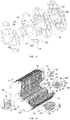
- Example 1 Compared with Example 1, this example has the following difference: when the rotor spacer 16 is manufactured in Step 2), with finite element analysis, the rotor spacer is opened and provided thereon with a lightening hole reducing the weight of the rotor spacer and lowering the stress concentration. Multiple lightening holes 166 are uniformly distributed around each permanent-magnet through hole 165. Multiple lightening holes 166 around the same permanent magnet 13 form one lightening-hole group. The lightening-hole groups are symmetrically distributed on the rotor spacer 16. The lightening hole 166 is a hole circled by a smooth curve.
- the lightening hole 166 is a circular hole, a kidney-shaped hole, or a polygonal hole with arc transition at its corner.
- the lightening hole is mainly concentrated at the corner of the permanent-body through hole. The rest manufacturing steps are all the same.
- the structure of the third rotor spacer 16c is showed in Fig. 10 .
- the inner sides 163c and 164c of the permanent-magnet through hole of the rotor spacer 16c is used for realizing the radial positioning of the permanent magnet 13 relative to the rotor shaft 10.
- the inner sides 165c are used for the circumferential positioning of the permanent magnet 13 relative to the rotor shaft 10.
- the key slot 164 and an inner circular hole 163 are used for realizing the circumferential and radial positioning of the rotor spacer 16c relative to the rotor shaft 10.
- the lightening hole of this rotor spacer 16c is a circular hole or a polygonal hole with arc transition at its corner.
- the lightening 166 is distributed at one side of the permanent-magnet through hole, which is close to the rotor iron core 15.
- the structure of the fourth rotor spacer 16d is showed in Fig. 11 .
- the inner sides 163d and 164d of the permanent-magnet through hole of the rotor spacer 16d is used for realizing the radial positioning of the permanent magnet 13 relative to the rotor shaft 10.
- the inner sides 165d are used for the circumferential positioning of the permanent magnet 13 relative to the rotor shaft 10.
- the inner circular arcs 166d, 167d and 168d are all transition circular arcs provided to lower the stress concentration.
- the key slot 164 and an inner circular hole 163 are used for realizing the circumferential and radial positioning of the rotor spacer 16d relative to the rotor shaft 10.
- the lightening hole of this rotor spacer 16d is a circular hole or a polygonal hole with arc transition at its corner.
- the lightening 166 is distributed at one side of the permanent-magnet through hole, which is close to the rotor iron core 15.
- Step 7 when the front end cover 11 and the rear end cover 12 are installed, two ends of each pole-shoe tightening bolt are opened and provided with a mounting bolt hole.
- the front end cover 11 and the rear end cover 12 are respectively provided thereon with a fixing bolt hole aligning with the pole-shoe tightening bolt 23 one by one.
- the fixing bolt hole is aligned to the mounting bolt hole.
- the bolt is inserted into the mounting bolt hole and fastened, thus completing the installation of the front end cover 11 and the rear end cover 12.
- the rest manufacturing steps are all the same.
- the front end plate 11 and the rear end plate of the rotor are made of a thicker non-magnetic plate material or a thicker plate material with low magnetic permeability (for example, high-strength austenitic stainless steel, etc.). This not only may stabilize the rotor pole shoe 14, the rotor spacer 16 and the permanent magnet 13 but also may be taken as a de-weighting structure when the permanent motor rotor is carried out with balance modification.
- the tightening bolt 17 of the front end plate through an external thread, is jointed with an inner thread hole 233 at the front end of the pole-shoe tightening bolt 23, thus facilitating the front end plate 11 and the pole-shoe tightening bolt 23 to be jointed with each other, and facilitating the inner side 112 of the front end plate 11 of the rotor to closely stand against the front side 147 of the rotor pole shoe 14 at the front end of the rotor.
- the outer surface of the back end of the pole-shoe tightening bolt 23 has the external thread 232.
- the external thread 232 is jointed with the nut of the pole-shoe tightening bolt to realize the fastening of the rotor pole shoe 14 and the rotor spacer 16.
- the lock washer is placed between the nut 20 of the pole-shoe tightening bolt and the rear side 148 of the rotor pole shoe at the back end of the rotor to prevent the nut of the pole-shoe tightening bolt from becoming loosed.
- the thread fitting between the external thread 232 of the pole-shoe tightening bolt 23 and the nut 20 of the pole-shoe tightening bolt is coated therein with the metal glue to realize the tight connection therebetween.
- the tightening bolt 18 of the back end plate through the external thread, is jointed with an inner thread hole 231 at the back end of the pole-shoe tightening bolt 23, thus facilitating the back end plate 12 and the pole-shoe tightening bolt 23 to be jointed with each other, and facilitating the inner side 121 of the back end plate 12 of the rotor to closely stand against the back side 148 of the rotor pole shoe 14 at the back end of the rotor.
- a small gap is preserved between the inner hole 111 of the front end plate of the rotor and the shaft ring 102 of the rotor shaft 10, thus preventing the front end plate 11 and the rotor shaft 10 from being interfered during the assembly of the rotor.
Claims (8)
- Verfahren zur Herstellung eines Permanentmagnet-Motorrotors, wobei der Permanentmagnet-Motorrotor ein vorderes Ende an einem ersten axialen Ende des Rotors und ein hinteres Ende an dem Ende des Rotors aufweist, das dem ersten axialen Ende axial gegenüberliegt, wobei das Verfahren die folgenden Schritte in der folgenden Reihenfolge aufweist:Schritt 1) Herstellung einer Drehwelle (10), eines Permanentmagneten (13), einer Abdeckung (11) für das vordere Ende und einer Abdeckung (12) für das hintere Ende ; Herstellung einer Vielzahl magnetischer Jocheinheiten (A), wobei jede magnetische Jocheinheit (A) mehrere Polschuhteile (A1) und einen Eisenkernteil (A2) aufweist, wobei die Polschuhteile (A1) um den Eisenkernteil (A2) herum angeordnet sind, wobei die Polschuhteile (A1) unabhängig voneinander ausgebildet und gleichmäßig um den Eisenkernteil (A2) herum verteilt sind, wobei jeder Polschuhteil (A1) und der Eisenkernteil (A2) miteinander über einen Verbindungsstreifen (145) verbunden sind, wobei der Polschuhteil (A1), der Verbindungsstreifen (145) und der Eisenkernteil (A2) ein Positionierungsloch (A4) ausbilden, das geeignet ist zur axialen und umlaufenden Positionierung des Permanentmagneten, wobei die Polschuhteile (A1) mit einem Durchgangsloch (A11) für einen Polschuhbolzen ausgestattet sind, welches das Durchdringen durch einen Polschuh-Spannbolzen (23) ermöglicht, und wobei der Eisenkernteil (A2) mit einem Durchgangsloch (A21) für einen Eisenkernbolzen versehen ist, welches das Durchdringen durch einen Eisenkern-Spannbolzen (24) ermöglicht;Schritt 2) Herstellung einer Vielzahl von Rotor-Abstandshaltern (16) aus einem nicht-magnetischen Material, wobei die Rotor-Abstandshalter (16) eine Rotorstruktur in mehrere Rotoreinheiten in axialer Richtung unterteilen, wobei jeder Rotor-Abstandshalter (16) mit einem Durchgangsloch (165) für einen Permanentmagneten versehen ist, das die Durchdringung durch den Permanentmagneten (13) und die radiale und axiale Positionierung des Permanentmagneten (13) gegenüber der Rotorwelle (10) ermöglicht, und wobei jeder Rotor-Abstandshalter (16) mit einem Durchgangsloch (161) für einen Polschuhbolzen versehen ist, das die Durchdringung durch den Polschuh-Spannbolzen (23) ermöglicht, und einem Durchgangsloch (162) für einen Eisenkernbolzen, das die Durchdringung durch den Eisenkern-Spannbolzen (24) ermöglicht;Schritt 3) Aufstülpen der magnetischen Jocheinheiten (16) und der Rotor-Abstandshalter (16) auf die Drehwelle (10), wobei sowohl die Verbindung zwischen der Drehwelle (10) und dem Eisenkernteil (A2) der magnetischen Jocheinheiten (A) als auch die Verbindung zwischen der Drehwelle (10) und den Rotor-Abstandshaltern (16) Passfederverbindungen sind, wobei die magnetischen Jocheinheiten (A) und die Rotor-Abstandshalter (16) in regelmäßigen axialen Abständen voneinander verteilt sind, und wobei die Rotor-Abstandshalter (16) die Rotorstruktur in mehrere Rotoreinheiten in axialer Richtung unterteilen;
wobei alle Positionierungslöcher (A4) der magnetischen Jocheinheiten (A) miteinander ausgerichtet sind, um einen Positionierungsdurchgang zu bilden; der Positionierungsdurchgang mit den Durchgangslöchern (165) für den Permanentmagneten der Rotor-Abstandshalter (16) ausgerichtet ist, um einen Permanentmagnetdurchgang zu bilden; die Durchgangslöcher (A11) für den Polschuhbolzen der magnetischen Jocheinheiten (A) mit den Durchgangslöchern (161) für den Polschuhbolzen der Rotor-Abstandshalter (16) eines nach dem anderen miteinander ausgerichtet sind, um einen Polschuhbolzen-Durchgang zu bilden, der die Durchdringung durch den Polschuh-Spannbolzen (23) ermöglicht; die Durchgangslöcher (A21) für den Eisenkernbolzen der magnetischen Jocheinheiten (A) mit den Durchgangslöchern (162) für den Eisenkernbolzen der Rotor-Abstandshalter (16) eines nach dem anderen miteinander ausgerichtet sind, um einen Eisenkernbolzen-Durchgang zu bilden, der die Durchdringung durch den Eisenkern-Spannbolzen (24) ermöglicht;Schritt 4) Einführen des Permanentmagneten (13) in den Permanentmagnetdurchgang, wobei der Permanentmagnet sich in Spielpassung mit dem Permanentmagnetdurchgang befindet;Schritt 5) Einführen des Polschuh-Spannbolzens (23) in jeden Polschuhbolzen-Durchgang, wobei der Polschuh-Spannbolzen (23) sich in Spielpassung mit dem Polschuhbolzen-Durchgang befindet; Einführen des Eisenkern-Spannbolzens (24) in jeden Eisenkernbolzen-Durchgang, wobei der Eisenkern-Spannbolzen (24) sich in Spielpassung mit dem Eisenkernbolzen-Durchgang befindet; unter Verwendung jeweils der beiden Enden des Spannbolzens zur Verbindung mit Muttern, um die magnetischen Jocheinheiten (A) und die Rotor-Abstandshalter (16) festzuziehen, wobei sich die Verbindungsstreifen (145) dabei auf den magnetischen Jocheinheiten (A) überlappen;Schritt 6) Abschneiden des Mittelbereichs jedes Verbindungsstreifens (145), so dass die Polschuhteile (A1) den Rotorpolschuh (14) bilden und die Eisenkernteile (A2) einen Rotoreisenkern (15) bilden, wobei der Rotorpolschuh (14) und der Rotoreisenkern (15) unabhängig voneinander ausgebildet sind;Schritt 7) Anordnung einer Abdeckung (11) für das vordere Ende und einer Abdeckung (12) für das hintere Ende jeweils an einem vorderen Ende der Rotorstruktur und an einem hinteren Ende der Rotorstruktur. - Verfahren zur Herstellung des Permanentmagnet-Motorrotors gemäß Anspruch 1, wobei sich in Schritt 1) mehrere Laminierungen überlappen, um die magnetischen Jocheinheiten (A) zu bilden.
- Verfahren zur Herstellung des Permanentmagnet-Motorrotors gemäß Anspruch 2, wobei in Schritt 1) jede magnetische Jocheinheit (A) aus einer ferromagnetischen Materialplatte gefertigt ist.
- Verfahren zur Herstellung des Permanentmagnet-Motorrotors gemäß Anspruch 1, wobei
in Schritt 1) ein Flachschlüssel (25) an der Drehwelle (10) vorgesehen wird; die Rotor-Abstandshalter (16) und der Rotoreisenkern (15) mit einem Durchgangsloch für die Drehwelle versehen werden, welches die Durchdringung für die Drehwelle (10) ermöglicht, und mit einem Schlüsselschlitz, der zu dem Flachschlüssel (25) passt; der Flachschlüssel (25) ist auf den Schlüsselschlitz abgestimmt, um die umlaufende Positionierung der Drehwelle (10) sowie des Rotoreisenkerns (15) und der Rotor-Abstandshalter (16) zu realisieren; und ein Wellenring (102) wird an der Drehwelle (10) vorgesehen, um die umlaufende Positionierung des Rotoreisenkerns (15) und der Rotor-Abstandshalter (16) bezüglich der Drehwelle (10) zu realisieren. - Verfahren zur Herstellung des Permanentmagnet-Motorrotors gemäß Anspruch 1, wobei
der Permanentmagnet (13) zwischen dem Rotorpolschuh (14) und dem Rotoreisenkern (15) ein Magnet aus einem einzigen Block ist. - Verfahren zur Herstellung des Permanentmagnet-Motorrotors gemäß Anspruch 1, wobei mehrere Permanentmagnete zwischen dem Rotorpolschuh (14) und dem Rotoreisenkern (15) axial entlang des Rotors zusammengefügt sind, um eine Permanentmagnetgruppe zu bilden; wobei die Permanentmagnetdurchgangslöcher (165) an den Rotor-Abstandshaltern (16) eins nach dem anderen mit dem Permanentmagneten (13) ausgerichtet sind; und wobei ein Anordnungsstreifen zwischen den benachbarten Permanentmagnetdurchgangslöchern (165) vorgesehen ist.
- Verfahren zur Herstellung des Permanentmagnet-Motorrotors gemäß Anspruch 1, wobei es in Schritt 2) eine glatte Übergangsrundung an der Ecke des Permanentmagnetdurchgangslochs (165) an den Rotor-Abstandshaltern (16) gibt, wodurch die Beanspruchungskonzentration der Rotor-Abstandshalter (16), die durch die Extrusion des Permanentmagneten (13) während der Drehung verursacht wird, vermindert wird.
- Verfahren zur Herstellung des Permanentmagnet-Motorrotors gemäß Anspruch 7, wobei in Schritt 2) mit einer Finite-Elemente-Analyse die Rotor-Abstandshalter (16) geöffnet und mit Lichtlöchern (166) versehen werden, wodurch das Gewicht der Rotor-Abstandshalter (16) und die Beanspruchungskonzentration verringert werden; wobei mehrere Lichtlöcher (166) gleichmäßig um jedes Permanentmagnetdurchgangsloch (165) herum verteilt werden; wobei mehrere Lichtlöcher (166) um denselben Permanentmagneten (13) herum eine Lichtlochgruppe bilden; wobei die Lichtlochgruppen symmetrisch an den Rotor-Abstandshaltern (16) verteilt sind; und wobei das Lichtloch (166) ein von einer glatten Rundung umgebenes Loch ist.
Applications Claiming Priority (2)
| Application Number | Priority Date | Filing Date | Title |
|---|---|---|---|
| CN201210019996.1A CN102545493B (zh) | 2012-01-22 | 2012-01-22 | 制造永磁电机转子的方法 |
| PCT/CN2012/074769 WO2013107128A1 (zh) | 2012-01-22 | 2012-04-26 | 制造永磁电机转子的方法 |
Publications (3)
| Publication Number | Publication Date |
|---|---|
| EP2806538A1 EP2806538A1 (de) | 2014-11-26 |
| EP2806538A4 EP2806538A4 (de) | 2016-04-13 |
| EP2806538B1 true EP2806538B1 (de) | 2021-02-17 |
Family
ID=46351655
Family Applications (1)
| Application Number | Title | Priority Date | Filing Date |
|---|---|---|---|
| EP12866347.3A Active EP2806538B1 (de) | 2012-01-22 | 2012-04-26 | Verfahren zur herstellung eines rotors für einen permanentmagnetmotor |
Country Status (5)
| Country | Link |
|---|---|
| US (1) | US9559572B2 (de) |
| EP (1) | EP2806538B1 (de) |
| JP (1) | JP5764724B2 (de) |
| CN (1) | CN102545493B (de) |
| WO (1) | WO2013107128A1 (de) |
Families Citing this family (28)
| Publication number | Priority date | Publication date | Assignee | Title |
|---|---|---|---|---|
| US9246364B2 (en) * | 2012-10-15 | 2016-01-26 | Regal Beloit America, Inc. | Radially embedded permanent magnet rotor and methods thereof |
| CN103390973B (zh) * | 2013-07-16 | 2016-09-28 | 贵州航天林泉电机有限公司 | 一种电机跟踪磁钢加压固化工艺 |
| WO2015190033A1 (ja) * | 2014-06-09 | 2015-12-17 | 富士電機株式会社 | 永久磁石式回転電機の回転子 |
| CN104410221B (zh) * | 2014-12-17 | 2016-11-23 | 哈尔滨电气动力装备有限公司 | 大型屏蔽电机转子冲片热叠压工艺 |
| CN106033912A (zh) * | 2015-03-12 | 2016-10-19 | 德昌电机(深圳)有限公司 | 电机 |
| CN104779721B (zh) * | 2015-04-09 | 2019-01-18 | 深圳市理想节能电机有限公司 | 转子及具有该转子的电机 |
| CN105322676A (zh) * | 2015-10-13 | 2016-02-10 | 南昌康富科技股份有限公司 | 一种凸极整体转子的十极发电机 |
| US10389196B2 (en) * | 2016-03-31 | 2019-08-20 | Nidec Motor Corporation | Spoked rotor with tapered pole segments and tapered ear recesses |
| JP6409837B2 (ja) * | 2016-09-08 | 2018-10-24 | トヨタ自動車株式会社 | 回転電機ロータ及び回転電機ロータの製造方法 |
| DE112017004967T5 (de) | 2016-09-30 | 2019-06-13 | Nidec Corporation | Rotorkern, rotor, motor, herstellungsverfahren eines rotorkerns und herstellungsverfahren eines rotors |
| WO2018062488A1 (ja) * | 2016-09-30 | 2018-04-05 | 日本電産株式会社 | ロータコア、ロータ、及びモータ |
| DE112017004955T5 (de) | 2016-09-30 | 2019-06-13 | Nidec Corporation | Herstellungsverfahren eines Motorkerns, Herstellungsverfahren eines Rotorkerns und Herstellungsverfahren eines Rotors |
| US11056938B2 (en) | 2016-09-30 | 2021-07-06 | Nidec Corporation | Rotor and motor |
| CN106451950B (zh) * | 2016-12-22 | 2023-03-21 | 珠海精实测控技术股份有限公司 | 转子贴磁瓦一体机 |
| JP7047775B2 (ja) * | 2016-12-28 | 2022-04-05 | 日本電産株式会社 | ロータコアの製造方法、ロータ、およびモータ |
| CN106981950A (zh) * | 2017-05-17 | 2017-07-25 | 襄阳华博士新能源科技有限公司 | 一种基于热管的新型风冷电机 |
| CN107394977A (zh) * | 2017-09-07 | 2017-11-24 | 宁德时代电机科技有限公司 | 一种新能源电机用的自动快速磁钢装配装置 |
| CN107465316B (zh) * | 2017-09-07 | 2023-05-23 | 宁德时代电机科技有限公司 | 一种新能源电机用多层自动快速插磁钢装置 |
| JP7059058B2 (ja) * | 2018-03-15 | 2022-04-25 | 本田技研工業株式会社 | 回転電機のロータ |
| JP7059059B2 (ja) * | 2018-03-15 | 2022-04-25 | 本田技研工業株式会社 | 回転電機のロータ |
| CN110690775B (zh) * | 2018-07-05 | 2021-11-19 | 爱信艾达株式会社 | 转子以及旋转电机 |
| JP2020054210A (ja) * | 2018-09-28 | 2020-04-02 | 日本電産株式会社 | ロータ、およびモータ |
| DE102018127501A1 (de) | 2018-11-05 | 2020-05-07 | C. & E. Fein Gmbh | EC-Motor für ein elektrisches Handwerkzeug sowie Verfahren zur Herstellung eines Rotors für einen EC-Motor |
| CN109412365B (zh) * | 2018-12-04 | 2023-10-20 | 宁波菲仕运动控制技术有限公司 | 一种高精度转子磁钢装配工装 |
| CN109768637B (zh) * | 2018-12-15 | 2024-04-05 | 宁德时代电机科技有限公司 | 外置矩形散热水管和机壳注导热胶的低温升永磁驱动电机 |
| US20220069649A1 (en) * | 2019-01-10 | 2022-03-03 | Vestas Wind Systems A/S | A generator rotor assembly |
| CN110336398A (zh) * | 2019-08-12 | 2019-10-15 | 安徽德科电气科技有限公司 | 一种高效节能的稀土永磁发电机 |
| CN115882647A (zh) * | 2021-09-28 | 2023-03-31 | 法雷奥汽车动力系统(上海)有限公司 | 电机转子、电机、车辆以及电机转子的组装方法 |
Family Cites Families (25)
| Publication number | Priority date | Publication date | Assignee | Title |
|---|---|---|---|---|
| JPS589500Y2 (ja) * | 1977-06-24 | 1983-02-21 | 株式会社デンソー | 磁石発電機の回転子 |
| US4327302A (en) * | 1979-09-21 | 1982-04-27 | General Electric Company | Electronically commutated motor, stationary and rotatable assemblies therefore, and lamination |
| US4469970A (en) * | 1981-12-24 | 1984-09-04 | General Electric Company | Rotor for permanent magnet excited synchronous motor |
| JPS5959055A (ja) * | 1982-09-27 | 1984-04-04 | Fanuc Ltd | 永久磁石界磁回転子 |
| US5345669A (en) * | 1988-06-08 | 1994-09-13 | General Electric Company | Method of making a permanent magnet rotor |
| US5563463A (en) * | 1988-06-08 | 1996-10-08 | General Electric Company | Permanent magnet rotor |
| US5237737A (en) * | 1988-06-08 | 1993-08-24 | General Electric Company | Method of making a permanent magnet rotor |
| US5881448A (en) * | 1992-04-06 | 1999-03-16 | General Electric Company | Method for making permanent magnet rotor |
| US5296773A (en) * | 1993-04-20 | 1994-03-22 | General Motors Corporation | Composite rotor for a synchronous reluctance machine |
| JP3558308B2 (ja) * | 1995-04-25 | 2004-08-25 | 富士電機システムズ株式会社 | 回転子磁極極性の判別可能な永久磁石形同期電動機 |
| US6064134A (en) * | 1998-07-24 | 2000-05-16 | General Motors Corporation | Rotor for a synchronous reluctance machine |
| JP2001157396A (ja) * | 1999-11-29 | 2001-06-08 | Mitsubishi Electric Corp | 回転電機の回転子及び回転子コアの製造方法 |
| JP2002136011A (ja) * | 2000-10-26 | 2002-05-10 | Fujitsu General Ltd | 永久磁石電動機 |
| JP2002191143A (ja) | 2000-12-20 | 2002-07-05 | Nissan Motor Co Ltd | 永久磁石式同期モータとそのモータを備えた自動車 |
| JP4012828B2 (ja) * | 2003-01-24 | 2007-11-21 | 株式会社三井ハイテック | 積層鉄心の製造方法 |
| CN2646941Y (zh) * | 2003-09-15 | 2004-10-06 | 上海海运学院 | 一种高效永磁同步电机 |
| JP2008099479A (ja) * | 2006-10-13 | 2008-04-24 | Mayekawa Mfg Co Ltd | 回転電機における磁石埋め込み型ロータと該ロータを用いた回転電機 |
| JP2008228395A (ja) | 2007-03-09 | 2008-09-25 | Daikin Ind Ltd | モータ回転子およびそれを備えた圧縮機 |
| JP2009195088A (ja) * | 2008-02-18 | 2009-08-27 | Toyota Industries Corp | 回転電機及びその製造方法 |
| DE102008032844A1 (de) * | 2008-07-14 | 2010-01-21 | Hanning Elektro-Werke Gmbh & Co. Kg | Permanentmagnetischer Rotor |
| JP5272713B2 (ja) * | 2008-12-24 | 2013-08-28 | Jfeスチール株式会社 | Ipmモータ用ロータコア |
| DE102010031399A1 (de) * | 2010-07-15 | 2012-01-19 | Hilti Aktiengesellschaft | Rotor für einen Elektromotor, Elektromotor und Herstellungsverfahren für einen Elektromotor |
| CN201797389U (zh) * | 2010-09-13 | 2011-04-13 | 浙江西子富沃德电机有限公司 | 永磁同步电机转子 |
| CN102005838B (zh) * | 2010-10-20 | 2012-11-14 | 东元总合科技(杭州)有限公司 | 大功率永磁电机转子,该转子的安装方法及该转子永磁体的充磁方法 |
| CN102545435B (zh) | 2012-01-22 | 2014-11-19 | 浙江大学 | 分段式永磁同步电机转子结构 |
-
2012
- 2012-01-22 CN CN201210019996.1A patent/CN102545493B/zh active Active
- 2012-04-26 WO PCT/CN2012/074769 patent/WO2013107128A1/zh active Application Filing
- 2012-04-26 US US14/373,616 patent/US9559572B2/en active Active
- 2012-04-26 JP JP2014547675A patent/JP5764724B2/ja active Active
- 2012-04-26 EP EP12866347.3A patent/EP2806538B1/de active Active
Non-Patent Citations (1)
| Title |
|---|
| None * |
Also Published As
| Publication number | Publication date |
|---|---|
| US9559572B2 (en) | 2017-01-31 |
| JP5764724B2 (ja) | 2015-08-19 |
| CN102545493A (zh) | 2012-07-04 |
| WO2013107128A1 (zh) | 2013-07-25 |
| EP2806538A4 (de) | 2016-04-13 |
| JP2015502132A (ja) | 2015-01-19 |
| US20150026966A1 (en) | 2015-01-29 |
| CN102545493B (zh) | 2014-03-05 |
| EP2806538A1 (de) | 2014-11-26 |
Similar Documents
| Publication | Publication Date | Title |
|---|---|---|
| EP2806538B1 (de) | Verfahren zur herstellung eines rotors für einen permanentmagnetmotor | |
| CN111010008B (zh) | 一种高强度轴向磁场电机表贴式永磁转子盘 | |
| US10651695B2 (en) | Disc rotor motor | |
| US7714479B2 (en) | Segmented composite rotor | |
| EP2869433B1 (de) | Permanentmagnetisch erregte elektrische Axialflussmaschine mit Flusskonzentration | |
| WO2014034344A1 (ja) | 回転電機 | |
| WO2011114594A1 (ja) | 永久磁石形回転電機 | |
| US7518278B2 (en) | High strength undiffused brushless machine and method | |
| CN102545435B (zh) | 分段式永磁同步电机转子结构 | |
| US7719156B2 (en) | Stator module | |
| US20120133230A1 (en) | Split-pole magnetic module for electric machine rotors | |
| WO2005101615A1 (en) | Permanent magnet rotor and magnet cradle | |
| KR101618717B1 (ko) | 자기폴 및 관련 로터를 설치하는 방법 | |
| JP2018082605A (ja) | スリーブロータ同期リラクタンス電気機械 | |
| JP2016532414A (ja) | 電気機械のためのロータ | |
| CN102545434B (zh) | 一种径向式永磁同步电机转子结构 | |
| EP3001542B1 (de) | Permanentmagnetrotoren | |
| EP2919369A1 (de) | Elektromagnetischer generator | |
| CN202634109U (zh) | 分段式永磁同步电机转子结构 | |
| EP2132857A2 (de) | Elektrische maschine mit axialflux | |
| CN102570665A (zh) | 径向式永磁同步电机转子结构 | |
| CN202513696U (zh) | 切向式永磁同步电机转子结构 | |
| CN102570666A (zh) | 切向式永磁同步电机转子结构 | |
| CN202634110U (zh) | 一种径向式永磁同步电机转子结构 | |
| JP2011172432A (ja) | 埋込磁石同期モータのロータ |
Legal Events
| Date | Code | Title | Description |
|---|---|---|---|
| PUAI | Public reference made under article 153(3) epc to a published international application that has entered the european phase |
Free format text: ORIGINAL CODE: 0009012 |
|
| 17P | Request for examination filed |
Effective date: 20140808 |
|
| AK | Designated contracting states |
Kind code of ref document: A1 Designated state(s): AL AT BE BG CH CY CZ DE DK EE ES FI FR GB GR HR HU IE IS IT LI LT LU LV MC MK MT NL NO PL PT RO RS SE SI SK SM TR |
|
| DAX | Request for extension of the european patent (deleted) | ||
| RA4 | Supplementary search report drawn up and despatched (corrected) |
Effective date: 20160311 |
|
| RIC1 | Information provided on ipc code assigned before grant |
Ipc: H02K 15/03 20060101ALN20160307BHEP Ipc: H02K 1/27 20060101AFI20160307BHEP |
|
| STAA | Information on the status of an ep patent application or granted ep patent |
Free format text: STATUS: REQUEST FOR EXAMINATION WAS MADE |
|
| STAA | Information on the status of an ep patent application or granted ep patent |
Free format text: STATUS: EXAMINATION IS IN PROGRESS |
|
| 17Q | First examination report despatched |
Effective date: 20180327 |
|
| RIC1 | Information provided on ipc code assigned before grant |
Ipc: H02K 15/03 20060101ALN20200225BHEP Ipc: H02K 1/27 20060101AFI20200225BHEP |
|
| RIC1 | Information provided on ipc code assigned before grant |
Ipc: H02K 1/27 20060101AFI20200319BHEP Ipc: H02K 15/03 20060101ALN20200319BHEP |
|
| RIC1 | Information provided on ipc code assigned before grant |
Ipc: H02K 1/27 20060101AFI20201020BHEP Ipc: H02K 15/03 20060101ALN20201020BHEP |
|
| GRAP | Despatch of communication of intention to grant a patent |
Free format text: ORIGINAL CODE: EPIDOSNIGR1 |
|
| STAA | Information on the status of an ep patent application or granted ep patent |
Free format text: STATUS: GRANT OF PATENT IS INTENDED |
|
| RIC1 | Information provided on ipc code assigned before grant |
Ipc: H02K 1/27 20060101AFI20201026BHEP Ipc: H02K 15/03 20060101ALN20201026BHEP |
|
| RIC1 | Information provided on ipc code assigned before grant |
Ipc: H02K 1/27 20060101AFI20201111BHEP Ipc: H02K 15/03 20060101ALN20201111BHEP |
|
| GRAS | Grant fee paid |
Free format text: ORIGINAL CODE: EPIDOSNIGR3 |
|
| INTG | Intention to grant announced |
Effective date: 20201201 |
|
| GRAA | (expected) grant |
Free format text: ORIGINAL CODE: 0009210 |
|
| STAA | Information on the status of an ep patent application or granted ep patent |
Free format text: STATUS: THE PATENT HAS BEEN GRANTED |
|
| AK | Designated contracting states |
Kind code of ref document: B1 Designated state(s): AL AT BE BG CH CY CZ DE DK EE ES FI FR GB GR HR HU IE IS IT LI LT LU LV MC MK MT NL NO PL PT RO RS SE SI SK SM TR |
|
| REG | Reference to a national code |
Ref country code: GB Ref legal event code: FG4D |
|
| REG | Reference to a national code |
Ref country code: CH Ref legal event code: EP |
|
| REG | Reference to a national code |
Ref country code: DE Ref legal event code: R096 Ref document number: 602012074438 Country of ref document: DE |
|
| REG | Reference to a national code |
Ref country code: AT Ref legal event code: REF Ref document number: 1362771 Country of ref document: AT Kind code of ref document: T Effective date: 20210315 |
|
| REG | Reference to a national code |
Ref country code: IE Ref legal event code: FG4D |
|
| REG | Reference to a national code |
Ref country code: LT Ref legal event code: MG9D |
|
| REG | Reference to a national code |
Ref country code: NL Ref legal event code: MP Effective date: 20210217 |
|
| PG25 | Lapsed in a contracting state [announced via postgrant information from national office to epo] |
Ref country code: PT Free format text: LAPSE BECAUSE OF FAILURE TO SUBMIT A TRANSLATION OF THE DESCRIPTION OR TO PAY THE FEE WITHIN THE PRESCRIBED TIME-LIMIT Effective date: 20210617 Ref country code: LT Free format text: LAPSE BECAUSE OF FAILURE TO SUBMIT A TRANSLATION OF THE DESCRIPTION OR TO PAY THE FEE WITHIN THE PRESCRIBED TIME-LIMIT Effective date: 20210217 Ref country code: HR Free format text: LAPSE BECAUSE OF FAILURE TO SUBMIT A TRANSLATION OF THE DESCRIPTION OR TO PAY THE FEE WITHIN THE PRESCRIBED TIME-LIMIT Effective date: 20210217 Ref country code: FI Free format text: LAPSE BECAUSE OF FAILURE TO SUBMIT A TRANSLATION OF THE DESCRIPTION OR TO PAY THE FEE WITHIN THE PRESCRIBED TIME-LIMIT Effective date: 20210217 Ref country code: GR Free format text: LAPSE BECAUSE OF FAILURE TO SUBMIT A TRANSLATION OF THE DESCRIPTION OR TO PAY THE FEE WITHIN THE PRESCRIBED TIME-LIMIT Effective date: 20210518 Ref country code: BG Free format text: LAPSE BECAUSE OF FAILURE TO SUBMIT A TRANSLATION OF THE DESCRIPTION OR TO PAY THE FEE WITHIN THE PRESCRIBED TIME-LIMIT Effective date: 20210517 Ref country code: NO Free format text: LAPSE BECAUSE OF FAILURE TO SUBMIT A TRANSLATION OF THE DESCRIPTION OR TO PAY THE FEE WITHIN THE PRESCRIBED TIME-LIMIT Effective date: 20210517 |
|
| REG | Reference to a national code |
Ref country code: AT Ref legal event code: MK05 Ref document number: 1362771 Country of ref document: AT Kind code of ref document: T Effective date: 20210217 |
|
| PG25 | Lapsed in a contracting state [announced via postgrant information from national office to epo] |
Ref country code: SE Free format text: LAPSE BECAUSE OF FAILURE TO SUBMIT A TRANSLATION OF THE DESCRIPTION OR TO PAY THE FEE WITHIN THE PRESCRIBED TIME-LIMIT Effective date: 20210217 Ref country code: NL Free format text: LAPSE BECAUSE OF FAILURE TO SUBMIT A TRANSLATION OF THE DESCRIPTION OR TO PAY THE FEE WITHIN THE PRESCRIBED TIME-LIMIT Effective date: 20210217 Ref country code: LV Free format text: LAPSE BECAUSE OF FAILURE TO SUBMIT A TRANSLATION OF THE DESCRIPTION OR TO PAY THE FEE WITHIN THE PRESCRIBED TIME-LIMIT Effective date: 20210217 Ref country code: RS Free format text: LAPSE BECAUSE OF FAILURE TO SUBMIT A TRANSLATION OF THE DESCRIPTION OR TO PAY THE FEE WITHIN THE PRESCRIBED TIME-LIMIT Effective date: 20210217 Ref country code: PL Free format text: LAPSE BECAUSE OF FAILURE TO SUBMIT A TRANSLATION OF THE DESCRIPTION OR TO PAY THE FEE WITHIN THE PRESCRIBED TIME-LIMIT Effective date: 20210217 |
|
| PG25 | Lapsed in a contracting state [announced via postgrant information from national office to epo] |
Ref country code: IS Free format text: LAPSE BECAUSE OF FAILURE TO SUBMIT A TRANSLATION OF THE DESCRIPTION OR TO PAY THE FEE WITHIN THE PRESCRIBED TIME-LIMIT Effective date: 20210617 |
|
| PG25 | Lapsed in a contracting state [announced via postgrant information from national office to epo] |
Ref country code: AT Free format text: LAPSE BECAUSE OF FAILURE TO SUBMIT A TRANSLATION OF THE DESCRIPTION OR TO PAY THE FEE WITHIN THE PRESCRIBED TIME-LIMIT Effective date: 20210217 Ref country code: SM Free format text: LAPSE BECAUSE OF FAILURE TO SUBMIT A TRANSLATION OF THE DESCRIPTION OR TO PAY THE FEE WITHIN THE PRESCRIBED TIME-LIMIT Effective date: 20210217 Ref country code: EE Free format text: LAPSE BECAUSE OF FAILURE TO SUBMIT A TRANSLATION OF THE DESCRIPTION OR TO PAY THE FEE WITHIN THE PRESCRIBED TIME-LIMIT Effective date: 20210217 Ref country code: CZ Free format text: LAPSE BECAUSE OF FAILURE TO SUBMIT A TRANSLATION OF THE DESCRIPTION OR TO PAY THE FEE WITHIN THE PRESCRIBED TIME-LIMIT Effective date: 20210217 |
|
| REG | Reference to a national code |
Ref country code: DE Ref legal event code: R097 Ref document number: 602012074438 Country of ref document: DE |
|
| PG25 | Lapsed in a contracting state [announced via postgrant information from national office to epo] |
Ref country code: MC Free format text: LAPSE BECAUSE OF FAILURE TO SUBMIT A TRANSLATION OF THE DESCRIPTION OR TO PAY THE FEE WITHIN THE PRESCRIBED TIME-LIMIT Effective date: 20210217 Ref country code: DK Free format text: LAPSE BECAUSE OF FAILURE TO SUBMIT A TRANSLATION OF THE DESCRIPTION OR TO PAY THE FEE WITHIN THE PRESCRIBED TIME-LIMIT Effective date: 20210217 Ref country code: ES Free format text: LAPSE BECAUSE OF FAILURE TO SUBMIT A TRANSLATION OF THE DESCRIPTION OR TO PAY THE FEE WITHIN THE PRESCRIBED TIME-LIMIT Effective date: 20210217 Ref country code: SK Free format text: LAPSE BECAUSE OF FAILURE TO SUBMIT A TRANSLATION OF THE DESCRIPTION OR TO PAY THE FEE WITHIN THE PRESCRIBED TIME-LIMIT Effective date: 20210217 Ref country code: RO Free format text: LAPSE BECAUSE OF FAILURE TO SUBMIT A TRANSLATION OF THE DESCRIPTION OR TO PAY THE FEE WITHIN THE PRESCRIBED TIME-LIMIT Effective date: 20210217 |
|
| PLBE | No opposition filed within time limit |
Free format text: ORIGINAL CODE: 0009261 |
|
| STAA | Information on the status of an ep patent application or granted ep patent |
Free format text: STATUS: NO OPPOSITION FILED WITHIN TIME LIMIT |
|
| PG25 | Lapsed in a contracting state [announced via postgrant information from national office to epo] |
Ref country code: LU Free format text: LAPSE BECAUSE OF NON-PAYMENT OF DUE FEES Effective date: 20210426 |
|
| REG | Reference to a national code |
Ref country code: BE Ref legal event code: MM Effective date: 20210430 |
|
| 26N | No opposition filed |
Effective date: 20211118 |
|
| PG25 | Lapsed in a contracting state [announced via postgrant information from national office to epo] |
Ref country code: LI Free format text: LAPSE BECAUSE OF NON-PAYMENT OF DUE FEES Effective date: 20210430 Ref country code: CH Free format text: LAPSE BECAUSE OF NON-PAYMENT OF DUE FEES Effective date: 20210430 Ref country code: AL Free format text: LAPSE BECAUSE OF FAILURE TO SUBMIT A TRANSLATION OF THE DESCRIPTION OR TO PAY THE FEE WITHIN THE PRESCRIBED TIME-LIMIT Effective date: 20210217 |
|
| PG25 | Lapsed in a contracting state [announced via postgrant information from national office to epo] |
Ref country code: SI Free format text: LAPSE BECAUSE OF FAILURE TO SUBMIT A TRANSLATION OF THE DESCRIPTION OR TO PAY THE FEE WITHIN THE PRESCRIBED TIME-LIMIT Effective date: 20210217 |
|
| PG25 | Lapsed in a contracting state [announced via postgrant information from national office to epo] |
Ref country code: IT Free format text: LAPSE BECAUSE OF FAILURE TO SUBMIT A TRANSLATION OF THE DESCRIPTION OR TO PAY THE FEE WITHIN THE PRESCRIBED TIME-LIMIT Effective date: 20210217 Ref country code: IE Free format text: LAPSE BECAUSE OF NON-PAYMENT OF DUE FEES Effective date: 20210426 |
|
| PG25 | Lapsed in a contracting state [announced via postgrant information from national office to epo] |
Ref country code: IS Free format text: LAPSE BECAUSE OF FAILURE TO SUBMIT A TRANSLATION OF THE DESCRIPTION OR TO PAY THE FEE WITHIN THE PRESCRIBED TIME-LIMIT Effective date: 20210617 |
|
| PG25 | Lapsed in a contracting state [announced via postgrant information from national office to epo] |
Ref country code: BE Free format text: LAPSE BECAUSE OF NON-PAYMENT OF DUE FEES Effective date: 20210430 |
|
| PG25 | Lapsed in a contracting state [announced via postgrant information from national office to epo] |
Ref country code: HU Free format text: LAPSE BECAUSE OF FAILURE TO SUBMIT A TRANSLATION OF THE DESCRIPTION OR TO PAY THE FEE WITHIN THE PRESCRIBED TIME-LIMIT; INVALID AB INITIO Effective date: 20120426 Ref country code: CY Free format text: LAPSE BECAUSE OF FAILURE TO SUBMIT A TRANSLATION OF THE DESCRIPTION OR TO PAY THE FEE WITHIN THE PRESCRIBED TIME-LIMIT Effective date: 20210217 |
|
| PGFP | Annual fee paid to national office [announced via postgrant information from national office to epo] |
Ref country code: FR Payment date: 20230428 Year of fee payment: 12 Ref country code: DE Payment date: 20230412 Year of fee payment: 12 |
|
| PGFP | Annual fee paid to national office [announced via postgrant information from national office to epo] |
Ref country code: GB Payment date: 20230424 Year of fee payment: 12 |
|
| PG25 | Lapsed in a contracting state [announced via postgrant information from national office to epo] |
Ref country code: MK Free format text: LAPSE BECAUSE OF FAILURE TO SUBMIT A TRANSLATION OF THE DESCRIPTION OR TO PAY THE FEE WITHIN THE PRESCRIBED TIME-LIMIT Effective date: 20210217 |