EP2806538B1 - Method for manufacturing permanent-magnet motor rotor - Google Patents
Method for manufacturing permanent-magnet motor rotor Download PDFInfo
- Publication number
- EP2806538B1 EP2806538B1 EP12866347.3A EP12866347A EP2806538B1 EP 2806538 B1 EP2806538 B1 EP 2806538B1 EP 12866347 A EP12866347 A EP 12866347A EP 2806538 B1 EP2806538 B1 EP 2806538B1
- Authority
- EP
- European Patent Office
- Prior art keywords
- rotor
- permanent
- magnet
- pole
- hole
- Prior art date
- Legal status (The legal status is an assumption and is not a legal conclusion. Google has not performed a legal analysis and makes no representation as to the accuracy of the status listed.)
- Active
Links
Images


Classifications
-
- H—ELECTRICITY
- H02—GENERATION; CONVERSION OR DISTRIBUTION OF ELECTRIC POWER
- H02K—DYNAMO-ELECTRIC MACHINES
- H02K15/00—Methods or apparatus specially adapted for manufacturing, assembling, maintaining or repairing of dynamo-electric machines
- H02K15/02—Methods or apparatus specially adapted for manufacturing, assembling, maintaining or repairing of dynamo-electric machines of stator or rotor bodies
- H02K15/03—Methods or apparatus specially adapted for manufacturing, assembling, maintaining or repairing of dynamo-electric machines of stator or rotor bodies having permanent magnets
-
- H—ELECTRICITY
- H02—GENERATION; CONVERSION OR DISTRIBUTION OF ELECTRIC POWER
- H02K—DYNAMO-ELECTRIC MACHINES
- H02K1/00—Details of the magnetic circuit
- H02K1/06—Details of the magnetic circuit characterised by the shape, form or construction
- H02K1/22—Rotating parts of the magnetic circuit
- H02K1/27—Rotor cores with permanent magnets
- H02K1/2706—Inner rotors
- H02K1/272—Inner rotors the magnetisation axis of the magnets being perpendicular to the rotor axis
- H02K1/274—Inner rotors the magnetisation axis of the magnets being perpendicular to the rotor axis the rotor consisting of two or more circumferentially positioned magnets
- H02K1/2753—Inner rotors the magnetisation axis of the magnets being perpendicular to the rotor axis the rotor consisting of two or more circumferentially positioned magnets the rotor consisting of magnets or groups of magnets arranged with alternating polarity
- H02K1/276—Magnets embedded in the magnetic core, e.g. interior permanent magnets [IPM]
-
- Y—GENERAL TAGGING OF NEW TECHNOLOGICAL DEVELOPMENTS; GENERAL TAGGING OF CROSS-SECTIONAL TECHNOLOGIES SPANNING OVER SEVERAL SECTIONS OF THE IPC; TECHNICAL SUBJECTS COVERED BY FORMER USPC CROSS-REFERENCE ART COLLECTIONS [XRACs] AND DIGESTS
- Y10—TECHNICAL SUBJECTS COVERED BY FORMER USPC
- Y10T—TECHNICAL SUBJECTS COVERED BY FORMER US CLASSIFICATION
- Y10T29/00—Metal working
- Y10T29/49—Method of mechanical manufacture
- Y10T29/49002—Electrical device making
- Y10T29/49009—Dynamoelectric machine
- Y10T29/49012—Rotor
Definitions
- the invention relates to a method for manufacturing a permanent-magnet motor rotor.
- a motor is an electromagnetic device taking magnetic field as media to carry out mutual conversion between mechanical energy and electrical energy.
- a motor winding is energized to generate a magnetic field, such as a conventional DC motor, the motor and so on.
- This electrically excited motor not only needs a special winding and a corresponding device but also needs to be continuously provided with energy to maintain its current flow.
- the magnetic field is generated by a permanent magnet. Due to the inherent characteristics of a permanent-magnet material, after it is pre-magnetized (magnetization), it does not need external energy to establish the magnetic field around its surrounding space; that is, it is the so-called permanent magnet motor.
- the permanent magnet motor Compared with the conventional excited motor, the permanent magnet motor has the advantages of simple structure, low loss, high power factor, high efficiency, high power density, high starting torque, low temperature, light weight and other obvious characteristics. With the continuous improvement and perfection of the magnetic properties in rare-earth permanent-magnet materials (especially NdFeB) and gradually reduced price, the permanent-magnet motor research and development gradually becomes mature, thus facilitating the permanent magnet motor to be more and more widely used in defense, industrial and agricultural production, daily life and so on.
- rare-earth permanent-magnet materials especially NdFeB
- the permanent-magnet motor is the motor which depends on the permanent magnet on a rotor to generate the magnet field.
- Its stator structure is basically identical to that of a common synchronous / asynchronous motor. That is, it consists of a stator iron core constituted by stacked silicon steel sheets and a stator coil embedded in an iron-core slot of the stator. It is energized by three-phase alternating current to generate a rotating magnetic field in the stator coil.
- the permanent-magnet motor rotor mainly consists of a rotor iron core and the permanent magnet, which is the main difference between the permanent-magnet motor and other type of the motor.
- a rotor magnetic circuit structure is the key technology of the permanent magnet motor. If a magnetic path structure adopted by the rotor is different, the operating performance, the control strategy, the manufacturing process and the use occasion of the motor are also different.
- the rotor magnetic path of the permanent-magnet motor may generally be divided into three types including a surface type, a built-in type and a claw-pole type.
- the surface-type rotor magnetic path has the advantages of simple structure and low manufacturing cost.
- this type permanent-magnet motor does not have asynchronous starting capability.
- the rotor has worse mechanical strength, and the permanent magnet is easily broken at high rotation speed.
- the permanent magnet of the built-in type permanent-magnet motor rotor is positioned inside the rotor.
- the magnetic path structure of the built-in type rotor can also be divided into three types including a radial type, a tangential type and a mixed type.
- the built-in permanent-magnet motor rotor may protect the permanent magnet with the lower mechanical properties.
- the size of the permanent magnet may be tremendously increased. Therefore, the structure of the permanent-magnet motor rotor is currently widely used.
- the conventional permanent-magnet motor rotor generally adopts a rotor guide strip to fasten the rotor.
- problems of low mechanical strength, poor reliability, severe eddy current loss of the rotor surface, obvious magnetic flux leakage, etc. These hinder the development of the permanent-magnet motor with high power, high speed and large rotary diameter, and furthermore limit the application of the permanent-magnet motor on high-speed trains as a traction motor.
- China patent application No. 201010513307.3 discloses a big-power permanent-magnet motor rotor and a method for mounting the rotor.
- the rotor Adopting a permanent-magnet embedded structure, the rotor consists of at least two rotor units along the axial direction. A magnet-separation groove along the rotor in the axial direction is opened and provided on an iron core between two adjacent permanent magnets of each rotor unit. A spacer made of a non-magnetic material is provided between the adjacent rotor units. An end plate is provided at two ends of the rotor unit. At least two rotor units are fixed through axially positioned tightening bolt.
- the permanent-magnet rotor has the following disadvantages: 1.
- the centrifugal force stressed by a rotor pole shoe is born jointly by an end plate, the spacer and a positioning tightening bolt. That is, the positioning tightening bolt fixing the rotor unit needs to bear bending moment.
- the centrifugal force is so large that the positioning tightening bolt is easily to be bended by the centrifugal force. That is, the rotor does not apply to the motor with high speed rotation.2.
- the magnet-separation groove is opened and provided at the iron core, the iron core, between the adjacent permanent magnet, still has a connection part.
- the magnetic field of the permanent magnet of adjacent poles through the direct communication of the iron core between the permanent magnets, causes magnetic flux leakage. That is, the structure cannot avoid magnetic flux leakage and has serious magnetic flux leakage. 3.
- the spacer is provided between two adjacent rotor units. The thickness of the spacer occupies the effective length of the rotor in the axial direction. When the number of the rotor units of the adopted rotor is increased and the thickness of the rotor spacer is increased, the effective length is dramatically reduced, thus affecting the electromagnetic properties of the rotor.
- JP2004-229442A discloses a method of manufacturing a laminated core in which a laminated body of segment pieces can be laminated without causing a positional shift, and furthermore a slit piece can be easily removed after lamination.
- the invention provides a method for manufacturing a permanent-magnet motor rotor, which may manufacture a motor with high mechanical strength and applicable for high-speed rotation.
- the present invention provides a method for manufacturing a permanent-magnet motor rotor as described in the claim 1, as well as some advantageous embodiments as described in the dependent claims.
- the lightening hole is a circular hole, a kidney-shaped hole, or a polygonal hole with arc transition at its comer; and the lightening hole is mainly concentrated at the comer of the permanent-body through hole.
- Step 4) the upper end surface of the permanent magnet and the lower end surface of the rotor pole shoe are fitted; there is a metal glue between the permanent magnet and the rotor pole shoe; the lower surface of the permanent magnet and the rotor iron core are fitted; and there is the metal glue between the permanent magnet and the rotor iron core.
- Step 5 a lock washer is placed between the nut of an iron-core tightening bolt and the rotor iron core to prevent the nut of the iron-core tightening bolt from becoming loosed; or the thread fitting between the iron-core tightening bolt and the nut is coated therein with the metal glue to realize the tight connection between the iron-core tightening bolt and the nut;
- Step 7) when the front end cover and the rear end cover are installed, two ends of each pole-shoe tightening bolt are opened and provided with a mounting bolt hole; the front end cover and the rear end cover are respectively provided thereon with a fixing bolt hole aligning with the pole-shoe tightening bolt one by one; the fixing bolt hole is aligned to a mounting bolt hole; and the bolt is inserted into the mounting bolt hole and fastened, thus completing the installation of the front end cover and the rear end cover.
- Step 7) after the front end cover and the rear end cover are installed, the gap between the rotor pole shoe and the rotor spacers is filled with a thermosetting polymer material, such as glass fiber reinforced plastics, epoxy resin, and so on.
- a thermosetting polymer material such as glass fiber reinforced plastics, epoxy resin, and so on.
- the invention has the following conception: the rotor spacer divides a rotor structure into multiple rotor units in the axially direction of the rotor structure; magnetic isolation is carried out for the rotor pole shoe of the adjacent rotor units through the rotor spacer.
- the rotor pole shoes are independent with each other and may not be in mutual communication, thus avoiding the magnetic flux leakage phenomenon.
- the rotor structure is close to the pole-shoe tightening bolt and the iron-core tightening bolt to be tightened tightly.
- Two ends of the rotor pole shoe closely stand against two rotor spacers, respectively.
- the centrifugal force, stressing on the rotor pole shoe and the permanent magnet when the rotor structure rotates is resisted by the friction between the rotor pole shoe and the rotor spacer.
- Two end surfaces of the rotor iron core closely stand against two the rotor spacers, respectively.
- the centrifugal force, stressing on the rotor pole shoe and the permanent magnet when the rotor structure rotates is resisted by the friction between the rotor iron core and the rotor spacer.
- the centrifugal force is also resisted by the mutual friction between the laminations of the rotor iron core, between the laminations of the rotor pole shoe and between the laminations of the rotor spacer.
- the friction between the rotor pole shoe and the rotor spacer is regulated based on the regulation of the tightening force of the pole-shoe tightening bolt.
- the pole-shoe tightening bolt only needs to bear the axial tensile force and does not need to bear the bending moment generated by the centrifugal force.
- the pole-shoe tightening bolt is not easy to be broken, and the rotor structure hence has long service life.
- the invention has the following effects: 1.
- the centrifugal force, generated when the rotor structure rotates, is resisted by the friction between the rotor pole shoe and the spacer.
- the tightening bolt is not easy to be bended and broken.
- the rotor structure has a long service life.
- the permanent magnet and the rotor iron core pass through the rotor spacer respectively. That is, the thickness of the rotor spacer does not occupy the axial length of the rotor structure.
- the rotor pole shoes are independent with each other, thus avoiding magnetic flux leakage phenomenon.
- a method for manufacturing a permanent-magnet motor rotor wherein the permanent-magnet motor rotor comprises a front end at a first axial end of the rotor and a rear end at the end of said rotor axially opposite to the first axial end, includes the following steps:
- thermosetting polymer material such as glass fiber reinforced plastics, epoxy resin, and so on.
- the magnetic yoke unit A is made of a ferromagnetic material plate with good magnetic property.
- a flat key 25 is provided on the rotary shaft 10.
- the rotor spacer 16 and the rotor iron core 15 are provided thereon with a rotary-shaft through hole allowing for penetration by the rotary shaft and a key slot matched with the flat key.
- the flat key 25 is matched with the key slot to realize the circumferential positioning of the rotary shaft as well as the rotor iron core 15 and the rotor spacer 16.
- a shaft ring 102 is provided on the rotary shaft 10 to realize the circumferential positioning of the rotor iron core 15 and the rotor spacer 16 which are relative to the rotary shaft.
- the permanent magnet 13 between the rotor pole shoe 14 and the rotor iron core 15 s a single-block magnet. Or multiple permanent magnets 13 between the rotor pole shoe 14 and the rotor iron core 15 are jointed along the rotor axially to form a permanent magnet group.
- the permanent-magnet through hole 165 on the rotor spacer 16 aligns with the permanent magnet 13 one by one.
- a placing strip is provided between the adjacent permanent-magnet through holes 165.
- the first rotor spacer 16a When the permanent magnet 13 is a single-block magnet, the first rotor spacer 16a is adopted.
- the structure of the first rotor spacer 16a is showed in Fig. 7 .
- the rotor spacer 16a, used for accommodating the through hole 165 of the permanent magnet 13, is an irregularly shaped hole constitution.
- the permanent magnet between the rotor pole shoe and the rotor iron core is a single-block magnet.
- the inner sides 163a and 164a of the permanent-magnet through hole 161 of the rotor spacer 16a are respectively and mutually close to and lean against the surfaces 133a and 131a of the permanent magnet 13a, thus realizing the radial positioning of the permanent magnet 13a relative to the rotor shaft 10.
- the inner sides 161a and 162a of the rotor spacer 16a are respectively and mutually close to and lean against two sides 132a of the permanent magnet 13a, thus realizing the circumferential positioning of the permanent magnet 13a relative to the rotor shaft 10, as shown in Fig. 8 .
- the second rotor spacer 16ba is adopted.
- the structure of the second rotor spacer is shown in Fig. 9 .
- Two permanent magnets between the rotor pole shoe and the rotor iron core are jointed axially along the rotor.
- the inner sides 163b and 164b of the rotor spacer 16b are used for realizing the radial positioning of the permanent magnet 13 relative to the rotor shaft 10.
- the inner sides 162b and 165b are used for realizing the circumferential positioning of the permanent magnet 13 relative to the rotor shaft 10.
- the key slot 164 and an inner circular hole 163 are used for realizing the circumferential and radial positioning of the rotor spacer 16b relative to the rotor shaft 10.
- One side of the through hole used for accommodating the permanent magnet 13 adopts two circular arcs 161b, and the other side thereof adopts a straight side 165b.
- the analysis of the 2D magnetic path of the permanent-magnet motor rotor is shown as Fig. 2 .
- the magnetic flow (magnetic line) of the magnetic field of the motor circulates based on the following paths:
- the magnetic line starts from current permanent magnet 13A, passes through the rotor pole shoe 14A, enters into a gas gap 28, passes through a stator tooth part 262, enters into a stator, reaches the area corresponding to adjacent poles in the stator along a yoke part 261 of the stator, enters into the gas gap through a tooth part of a stator, enters into the S pole of the adjacent permanent magnet through the adjacent rotor pole shoe 14B, enters into the rotor iron core 15 from the N pole, finally goes back to the N pole of the current permanent magnet 13 A, and forms a circuit of the magnetic line.
- the invention has the following conception:
- the rotor spacer 16 divides a rotor structure into multiple rotor units in the axially direction of the rotor structure. Magnetic isolation is carried out for the rotor pole shoe 14 of the adjacent rotor units through the rotor spacer 16. In the same rotor unit, the rotor pole shoes 14 are independent with each other and may not be in mutual communication, thus avoiding the magnetic flux leakage phenomenon.
- the rotor structure is close to the pole-shoe tightening bolt 23 and the iron-core tightening bolt 24 to be tightened tightly.
- Two ends of the rotor pole shoe 14 closely stand against two rotor spacers 16, respectively.
- the centrifugal force, stressing on the rotor pole shoe 14 and the permanent magnet 13 when the rotor structure rotates, is resisted based on the friction between the rotor pole shoe 14 and the rotor spacer 16.
- Two end surfaces of the rotor iron core 15 closely stand against two the rotor spacers 16, respectively.
- the centrifugal force, stressing on the rotor pole shoe and the permanent magnet when the rotor structure rotates is resisted by the friction between the rotor iron core 15 and the rotor spacer 16.
- the centrifugal force is also resisted by the mutual friction between the laminations of the rotor iron core 15, between the laminations of the rotor pole shoe 14 and between the laminations of the rotor spacer 16.
- the friction between the rotor pole shoe 14 and the rotor spacer 16 is regulated based on the regulation of the tightening force of the pole-shoe tightening bolt 23.
- the pole-shoe tightening bolt only needs to bear the axial tensile force and does not need to bear the bending moment generated by the centrifugal force.
- the pole-shoe tightening bolt is not easy to be broken, and the rotor structure hence has a long service life.
- the invention has the following effects: 1.
- the centrifugal force, generated when the rotor structure rotates, is resisted by the friction between the rotor pole shoe and the spacer.
- the pole-shoe tightening bolt is not easy to be bended and broken, and the rotor structure hence has a long service life.
- the permanent magnet and the rotor iron core pass through the rotor spacer respectively. That is, the thickness of the rotor spacer does not occupy the axial length of the rotor structure.
- the rotor pole shoes are independent with each other, thus avoiding magnetic flux leakage phenomenon.
- Example 1 Compared with Example 1, this example has the following difference: when the rotor spacer 16 is manufactured in Step 2), with finite element analysis, the rotor spacer is opened and provided thereon with a lightening hole reducing the weight of the rotor spacer and lowering the stress concentration. Multiple lightening holes 166 are uniformly distributed around each permanent-magnet through hole 165. Multiple lightening holes 166 around the same permanent magnet 13 form one lightening-hole group. The lightening-hole groups are symmetrically distributed on the rotor spacer 16. The lightening hole 166 is a hole circled by a smooth curve.
- the lightening hole 166 is a circular hole, a kidney-shaped hole, or a polygonal hole with arc transition at its corner.
- the lightening hole is mainly concentrated at the corner of the permanent-body through hole. The rest manufacturing steps are all the same.
- the structure of the third rotor spacer 16c is showed in Fig. 10 .
- the inner sides 163c and 164c of the permanent-magnet through hole of the rotor spacer 16c is used for realizing the radial positioning of the permanent magnet 13 relative to the rotor shaft 10.
- the inner sides 165c are used for the circumferential positioning of the permanent magnet 13 relative to the rotor shaft 10.
- the key slot 164 and an inner circular hole 163 are used for realizing the circumferential and radial positioning of the rotor spacer 16c relative to the rotor shaft 10.
- the lightening hole of this rotor spacer 16c is a circular hole or a polygonal hole with arc transition at its corner.
- the lightening 166 is distributed at one side of the permanent-magnet through hole, which is close to the rotor iron core 15.
- the structure of the fourth rotor spacer 16d is showed in Fig. 11 .
- the inner sides 163d and 164d of the permanent-magnet through hole of the rotor spacer 16d is used for realizing the radial positioning of the permanent magnet 13 relative to the rotor shaft 10.
- the inner sides 165d are used for the circumferential positioning of the permanent magnet 13 relative to the rotor shaft 10.
- the inner circular arcs 166d, 167d and 168d are all transition circular arcs provided to lower the stress concentration.
- the key slot 164 and an inner circular hole 163 are used for realizing the circumferential and radial positioning of the rotor spacer 16d relative to the rotor shaft 10.
- the lightening hole of this rotor spacer 16d is a circular hole or a polygonal hole with arc transition at its corner.
- the lightening 166 is distributed at one side of the permanent-magnet through hole, which is close to the rotor iron core 15.
- Step 7 when the front end cover 11 and the rear end cover 12 are installed, two ends of each pole-shoe tightening bolt are opened and provided with a mounting bolt hole.
- the front end cover 11 and the rear end cover 12 are respectively provided thereon with a fixing bolt hole aligning with the pole-shoe tightening bolt 23 one by one.
- the fixing bolt hole is aligned to the mounting bolt hole.
- the bolt is inserted into the mounting bolt hole and fastened, thus completing the installation of the front end cover 11 and the rear end cover 12.
- the rest manufacturing steps are all the same.
- the front end plate 11 and the rear end plate of the rotor are made of a thicker non-magnetic plate material or a thicker plate material with low magnetic permeability (for example, high-strength austenitic stainless steel, etc.). This not only may stabilize the rotor pole shoe 14, the rotor spacer 16 and the permanent magnet 13 but also may be taken as a de-weighting structure when the permanent motor rotor is carried out with balance modification.
- the tightening bolt 17 of the front end plate through an external thread, is jointed with an inner thread hole 233 at the front end of the pole-shoe tightening bolt 23, thus facilitating the front end plate 11 and the pole-shoe tightening bolt 23 to be jointed with each other, and facilitating the inner side 112 of the front end plate 11 of the rotor to closely stand against the front side 147 of the rotor pole shoe 14 at the front end of the rotor.
- the outer surface of the back end of the pole-shoe tightening bolt 23 has the external thread 232.
- the external thread 232 is jointed with the nut of the pole-shoe tightening bolt to realize the fastening of the rotor pole shoe 14 and the rotor spacer 16.
- the lock washer is placed between the nut 20 of the pole-shoe tightening bolt and the rear side 148 of the rotor pole shoe at the back end of the rotor to prevent the nut of the pole-shoe tightening bolt from becoming loosed.
- the thread fitting between the external thread 232 of the pole-shoe tightening bolt 23 and the nut 20 of the pole-shoe tightening bolt is coated therein with the metal glue to realize the tight connection therebetween.
- the tightening bolt 18 of the back end plate through the external thread, is jointed with an inner thread hole 231 at the back end of the pole-shoe tightening bolt 23, thus facilitating the back end plate 12 and the pole-shoe tightening bolt 23 to be jointed with each other, and facilitating the inner side 121 of the back end plate 12 of the rotor to closely stand against the back side 148 of the rotor pole shoe 14 at the back end of the rotor.
- a small gap is preserved between the inner hole 111 of the front end plate of the rotor and the shaft ring 102 of the rotor shaft 10, thus preventing the front end plate 11 and the rotor shaft 10 from being interfered during the assembly of the rotor.
Description
- The invention relates to a method for manufacturing a permanent-magnet motor rotor.
- A motor is an electromagnetic device taking magnetic field as media to carry out mutual conversion between mechanical energy and electrical energy. In order to establish an air-gap magnetic field inside of the motor needed by electromechanical energy conversion, two methods are provided. As to one method, a motor winding is energized to generate a magnetic field, such as a conventional DC motor, the motor and so on. This electrically excited motor not only needs a special winding and a corresponding device but also needs to be continuously provided with energy to maintain its current flow. As to the other method, the magnetic field is generated by a permanent magnet. Due to the inherent characteristics of a permanent-magnet material, after it is pre-magnetized (magnetization), it does not need external energy to establish the magnetic field around its surrounding space; that is, it is the so-called permanent magnet motor.
- Compared with the conventional excited motor, the permanent magnet motor has the advantages of simple structure, low loss, high power factor, high efficiency, high power density, high starting torque, low temperature, light weight and other obvious characteristics. With the continuous improvement and perfection of the magnetic properties in rare-earth permanent-magnet materials (especially NdFeB) and gradually reduced price, the permanent-magnet motor research and development gradually becomes mature, thus facilitating the permanent magnet motor to be more and more widely used in defense, industrial and agricultural production, daily life and so on.
- The permanent-magnet motor is the motor which depends on the permanent magnet on a rotor to generate the magnet field. Its stator structure is basically identical to that of a common synchronous / asynchronous motor. That is, it consists of a stator iron core constituted by stacked silicon steel sheets and a stator coil embedded in an iron-core slot of the stator. It is energized by three-phase alternating current to generate a rotating magnetic field in the stator coil. The permanent-magnet motor rotor mainly consists of a rotor iron core and the permanent magnet, which is the main difference between the permanent-magnet motor and other type of the motor. A rotor magnetic circuit structure is the key technology of the permanent magnet motor. If a magnetic path structure adopted by the rotor is different, the operating performance, the control strategy, the manufacturing process and the use occasion of the motor are also different.
- According to different installation locations of the permanent magnet in the permanent magnet motor rotor, the rotor magnetic path of the permanent-magnet motor may generally be divided into three types including a surface type, a built-in type and a claw-pole type. The surface-type rotor magnetic path has the advantages of simple structure and low manufacturing cost. However, as the surface of the rotor may not be mounted with a starting winding, this type permanent-magnet motor does not have asynchronous starting capability. Furthermore, the rotor has worse mechanical strength, and the permanent magnet is easily broken at high rotation speed. The permanent magnet of the built-in type permanent-magnet motor rotor is positioned inside the rotor. According to the relationship between the magnetization direction of the permanent magnet and the rotation direction of the rotor, the magnetic path structure of the built-in type rotor can also be divided into three types including a radial type, a tangential type and a mixed type. Compared with the surface type rotor, the built-in permanent-magnet motor rotor may protect the permanent magnet with the lower mechanical properties. According to performance requirements of the permanent-magnet motor, the size of the permanent magnet may be tremendously increased. Therefore, the structure of the permanent-magnet motor rotor is currently widely used.
- At present, the conventional permanent-magnet motor rotor generally adopts a rotor guide strip to fasten the rotor. However, there are still obvious problems of low mechanical strength, poor reliability, severe eddy current loss of the rotor surface, obvious magnetic flux leakage, etc. These hinder the development of the permanent-magnet motor with high power, high speed and large rotary diameter, and furthermore limit the application of the permanent-magnet motor on high-speed trains as a traction motor.
- China patent application No.
201010513307.3 - The permanent-magnet rotor has the following disadvantages: 1. The centrifugal force stressed by a rotor pole shoe is born jointly by an end plate, the spacer and a positioning tightening bolt. That is, the positioning tightening bolt fixing the rotor unit needs to bear bending moment. When the rotor rotates at high speed, the centrifugal force is so large that the positioning tightening bolt is easily to be bended by the centrifugal force. That is, the rotor does not apply to the motor with high speed rotation.2. Although the magnet-separation groove is opened and provided at the iron core, the iron core, between the adjacent permanent magnet, still has a connection part. The magnetic field of the permanent magnet of adjacent poles, through the direct communication of the iron core between the permanent magnets, causes magnetic flux leakage. That is, the structure cannot avoid magnetic flux leakage and has serious magnetic flux leakage. 3. The spacer is provided between two adjacent rotor units. The thickness of the spacer occupies the effective length of the rotor in the axial direction. When the number of the rotor units of the adopted rotor is increased and the thickness of the rotor spacer is increased, the effective length is dramatically reduced, thus affecting the electromagnetic properties of the rotor.
-
JP2004-229442A - In order to overcome the above defects in the prior art, the invention provides a method for manufacturing a permanent-magnet motor rotor, which may manufacture a motor with high mechanical strength and applicable for high-speed rotation.
- The present invention provides a method for manufacturing a permanent-magnet motor rotor as described in the
claim 1, as well as some advantageous embodiments as described in the dependent claims. - Furthermore, the lightening hole is a circular hole, a kidney-shaped hole, or a polygonal hole with arc transition at its comer; and the lightening hole is mainly concentrated at the comer of the permanent-body through hole.
- Furthermore, in Step 4): the upper end surface of the permanent magnet and the lower end surface of the rotor pole shoe are fitted; there is a metal glue between the permanent magnet and the rotor pole shoe; the lower surface of the permanent magnet and the rotor iron core are fitted; and there is the metal glue between the permanent magnet and the rotor iron core.
- Furthermore, in Step 5): a lock washer is placed between the nut of an iron-core tightening bolt and the rotor iron core to prevent the nut of the iron-core tightening bolt from becoming loosed; or the thread fitting between the iron-core tightening bolt and the nut is coated therein with the metal glue to realize the tight connection between the iron-core tightening bolt and the nut;
- Furthermore, in Step 7): when the front end cover and the rear end cover are installed, two ends of each pole-shoe tightening bolt are opened and provided with a mounting bolt hole; the front end cover and the rear end cover are respectively provided thereon with a fixing bolt hole aligning with the pole-shoe tightening bolt one by one; the fixing bolt hole is aligned to a mounting bolt hole; and the bolt is inserted into the mounting bolt hole and fastened, thus completing the installation of the front end cover and the rear end cover.
- Furthermore, in Step 7): after the front end cover and the rear end cover are installed, the gap between the rotor pole shoe and the rotor spacers is filled with a thermosetting polymer material, such as glass fiber reinforced plastics, epoxy resin, and so on.
- The invention has the following conception: the rotor spacer divides a rotor structure into multiple rotor units in the axially direction of the rotor structure; magnetic isolation is carried out for the rotor pole shoe of the adjacent rotor units through the rotor spacer. In the same rotor unit, the rotor pole shoes are independent with each other and may not be in mutual communication, thus avoiding the magnetic flux leakage phenomenon.
- The rotor structure is close to the pole-shoe tightening bolt and the iron-core tightening bolt to be tightened tightly. Two ends of the rotor pole shoe closely stand against two rotor spacers, respectively. The centrifugal force, stressing on the rotor pole shoe and the permanent magnet when the rotor structure rotates, is resisted by the friction between the rotor pole shoe and the rotor spacer. Two end surfaces of the rotor iron core closely stand against two the rotor spacers, respectively. The centrifugal force, stressing on the rotor pole shoe and the permanent magnet when the rotor structure rotates, is resisted by the friction between the rotor iron core and the rotor spacer. Meanwhile, the centrifugal force is also resisted by the mutual friction between the laminations of the rotor iron core, between the laminations of the rotor pole shoe and between the laminations of the rotor spacer. The friction between the rotor pole shoe and the rotor spacer is regulated based on the regulation of the tightening force of the pole-shoe tightening bolt. The pole-shoe tightening bolt only needs to bear the axial tensile force and does not need to bear the bending moment generated by the centrifugal force. The pole-shoe tightening bolt is not easy to be broken, and the rotor structure hence has long service life.
- The invention has the following effects: 1. The centrifugal force, generated when the rotor structure rotates, is resisted by the friction between the rotor pole shoe and the spacer. The tightening bolt is not easy to be bended and broken. The rotor structure has a long service life. 2. The permanent magnet and the rotor iron core pass through the rotor spacer respectively. That is, the thickness of the rotor spacer does not occupy the axial length of the rotor structure. 3. The rotor pole shoes are independent with each other, thus avoiding magnetic flux leakage phenomenon.
-
-
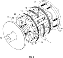
Fig. 1 is an exploded diagram of parts of a rotor of a permanent-magnet motor rotor. -
Fig. 2 is an analysis diagram of a permanent-magnet motor rotor and a stator magnetic field. -
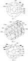
Fig. 3 is a diagram of a pole shoe part and an iron core part which are connected through a connecting strip. -
Fig. 4 is a diagram a pole shoe part and an iron core part which are separated and form a rotor pole shoe and a rotor iron core. -
Fig. 5 is a diagram of the assembly of a rotor pole shoe and a rotor iron core as well as a rotor spacer when a connecting strip is between a pole shoe part and an iron core part. -
Fig. 6 is a diagram of the assembly of a rotor pole shoe and a rotor iron core as well as a rotor spacer when a pole shoe part and an iron core part are under separate state. -
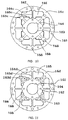
Fig. 7 is a diagram of the first permanent-magnet motor rotor spacer. -
Fig. 8 is an assembly diagram of the first permanent-magnet motor rotor spacer and a permanent magnet. -
Fig. 9 is a diagram of the second permanent-magnet motor rotor spacer. -
Fig. 10 is a diagram of the third permanent-magnet motor rotor spacer. -
Fig. 11 is a diagram of the fourth permanent-magnet motor rotor spacer. -
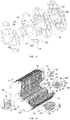
Fig. 12 is an exploded diagram of parts of a permanent-magnet motor rotor when the fourth spacer is used. -
Fig. 13 is an exploded diagram of a permanent magnet, a rotor pole shoe and a rotor spacer of a permanent-magnet motor rotor when the fourth spacer is used. -
Fig. 14 is a diagram of the mutual fitting among a shaft, a rotor iron core and a rotor spacer of a permanent-magnet motor rotor when the fourth spacer is used. -
Fig. 15 is an assembly diagram of a permanent-magnet motor rotor. - A method for manufacturing a permanent-magnet motor rotor, wherein the permanent-magnet motor rotor comprises a front end at a first axial end of the rotor and a rear end at the end of said rotor axially opposite to the first axial end, includes the following steps:
- Step 1) manufacturing a rotary shaft 10, a permanent magnet 13, a front end cover 11 and a rear end cover 12; manufacturing a plurality of magnetic yoke units A, where each magnetic yoke unit A comprises multiple pole shoe parts A1 and one iron core part A2, where the pole shoe parts A1 are arranged around the iron core part A2, where the pole shoe parts A1 are independent from each other and uniformly distributed around the iron core part A2, where each pole shoe part A1 and the iron core part A2 are connected together via a connecting strip 145, where the pole shoe part A1, the connecting strip 145, and the iron core part A2 form a positioning hole A4 suitable for positioning the permanent magnet axially and circumferentially, where the pole shoe parts A1 are provided with a pole-shoe bolt through hole A11 allowing for penetration by a pole-shoe tightening bolt 23, and where the iron core part A2 is provided with an iron-core bolt through hole A21 allowing for penetration by an iron-core tightening bolt 24; the permanent magnet 13 is made of Alnico, ferrite, rare earth or other permanent magnet materials, and used for generating the rotor magnetic field of a permanent-magnet motor; multiple laminations overlap to form the magnetic yoke unit A; of course, the magnetic yoke unit A is also in integral type.
- Step 2) manufacturing a plurality of rotor spacers 16 with a non-magnetic material, where the rotor spacers 16 divide a rotor structure into multiple rotor units in the axial direction, where each rotor spacer 16 is provided with a permanent-magnet through hole 165 allowing for penetration by the permanent magnet 13 and for radial and axial positioning of the permanent magnet 13 relative to the rotor shaft 10, and where each rotor spacer 16 is provided with a pole-shoe bolt through hole 161 allowing for penetration by the pole-shoe tightening bolt 23 and provided with an iron-core bolt through hole 162 allowing for penetration by the iron-core tightening bolt 24;; where the rotor spacer 16 is made of a non-magnetic material (for example, high strength aluminum alloy, carbon fiber, ceramic, etc.) or a plate material with low magnetic permeability (for example, high-strength austenitic stainless steel, titanium alloy, etc.), and used for bearing the centrifugal force stressed by the rotor pole shoe 14 and the permanent magnet 13 during the high-speed rotation; where laminations may overlap to form the rotor spacer 16 which may also be in an integral type; where the rotor spacer 16 includes the through hole 165 used for the radial and axial positioning of the permanent magnet 13 relative to the rotor shaft 10, a circular hole 161 used for accommodating the pole-shoe tightening bolt 23, the circular hole 162 used for accommodating the iron-core tightening bolt 24, and a center circular hole 163 used for matching the outer surface of the rotor shaft 10 for the radially positioning the rotor spacer 16 relative to the rotor shaft 10; and where the key slot 164 is matched with a key 25 on the rotor shaft 10 and used for circumferentially positioning the rotor spacer 16 relative to the rotor shaft 10.
- Step 3) sleeving the
magnetic yoke units 16 and therotor spacers 16 on therotary shaft 10, where the connection between therotary shaft 10 and the iron core part A2 of the magnetic yoke units A and the connection between therotary shaft 10 and therotor spacers 16 are both key connections, where the magnetic yoke units A and therotor spacers 16 are distributed at regular axial intervals, and where therotor spacers 16 divides the rotor structure into multiple rotor units in the axial direction;
all positioning holes A4 of the magnetic yoke units A align to form a positioning passage; the positioning passage aligns with the permanent-magnet throughhole 165 of therotor spacers 16 to form a permanent-magnet passage; the pole-shoe bolt through hole A11 of the magnetic yoke units A aligns with the pole-shoe bolt throughhole 161 of therotor spacers 16 one by one to form a pole-shoe bolt passage allowing for penetration by the pole-shoe tightening bolt 23; the iron-core bolt through hole A21 of the magnetic yoke units A aligns with the iron-core bolt throughhole 162 of therotor spacers 16 one by one to form an iron-core bolt passage allowing for penetration by the iron-core tightening bolt 24; - Step 4) inserting the
permanent magnet 13 into the permanent-magnet passage, where thepermanent magnet 13 is in clearance fit with a permanent-magnet passage; - Step 5) inserting the pole-
shoe tightening bolt 23 into each pole-shoe bolt passage, where the pole-shoe tightening bolt 23 is in clearance fit with the pole-shoe bolt passage; inserting the iron-core tightening bolt 24 into each iron-core bolt passage, where the iron-core tightening bolt 24 is in clearance fit with the iron-core bolt passage; using respectively the two ends of the tightening bolt to connect with nuts to tighten the magnetic yoke units A and therotor spacers 16, where the connectingstrip 145 on the magnetic yoke units A overlap each other at this time; where a lock washer is placed between the nut of an iron-core tightening bolt and the rotor iron core to prevent the nut of the iron-core tightening bolt 24 from becoming loosed; or the thread fitting between the iron-core tightening bolt 24 and the nut is coated therein with a metal glue to realize the tight connection between the iron-core tightening bolt 24 and the nut; - Step 6) cutting off the mid-section of each connecting
strip 145, so that the pole shoe parts A1 form therotor pole shoe 14, and the iron core parts A2 form arotor iron core 15, wherein therotor pole shoe 14 and therotor iron core 15 are independent from each other, where the upper end surface of thepermanent magnet 13 and the lower end surface of therotor pole shoe 16 are fitted, where there is the metal glue between thepermanent magnet 13 and therotor pole shoe 16, where the lower surface of thepermanent magnet 13 and therotor iron core 15 are fitted; and where there is the metal glue between thepermanent magnet 13 and therotor iron core 15; - Step 7) arranging a
front end cover 11 and a rear end cover 12 at a front end of the rotor structure and at a rear end of the rotor structure, respectively. - After the
front end cover 11 and therear end cover 12 are installed, the gap between therotor pole shoe 14 and therotor spacer 16 is filled with a thermosetting polymer material, such as glass fiber reinforced plastics, epoxy resin, and so on. - The magnetic yoke unit A is made of a ferromagnetic material plate with good magnetic property.
- A
flat key 25 is provided on the rotary shaft 10.Therotor spacer 16 and therotor iron core 15 are provided thereon with a rotary-shaft through hole allowing for penetration by the rotary shaft and a key slot matched with the flat key. Theflat key 25 is matched with the key slot to realize the circumferential positioning of the rotary shaft as well as therotor iron core 15 and therotor spacer 16. Ashaft ring 102 is provided on therotary shaft 10 to realize the circumferential positioning of therotor iron core 15 and therotor spacer 16 which are relative to the rotary shaft. - The
permanent magnet 13 between therotor pole shoe 14 and therotor iron core 15 s a single-block magnet. Or multiplepermanent magnets 13 between therotor pole shoe 14 and therotor iron core 15 are jointed along the rotor axially to form a permanent magnet group. The permanent-magnet throughhole 165 on therotor spacer 16 aligns with thepermanent magnet 13 one by one. A placing strip is provided between the adjacent permanent-magnet throughholes 165. - When the
permanent magnet 13 is a single-block magnet, thefirst rotor spacer 16a is adopted. The structure of thefirst rotor spacer 16a is showed inFig. 7 . Therotor spacer 16a, used for accommodating the throughhole 165 of thepermanent magnet 13, is an irregularly shaped hole constitution. The permanent magnet between the rotor pole shoe and the rotor iron core is a single-block magnet. Theinner sides hole 161 of therotor spacer 16a are respectively and mutually close to and lean against thesurfaces permanent magnet 13a, thus realizing the radial positioning of thepermanent magnet 13a relative to therotor shaft 10. Theinner sides rotor spacer 16a are respectively and mutually close to and lean against twosides 132a of thepermanent magnet 13a, thus realizing the circumferential positioning of thepermanent magnet 13a relative to therotor shaft 10, as shown inFig. 8 . - When the
permanent magnet 13 is the permanent-magnet group, the second rotor spacer 16ba is adopted. The structure of the second rotor spacer is shown inFig. 9 . Two permanent magnets between the rotor pole shoe and the rotor iron core are jointed axially along the rotor. Theinner sides 163b and 164b of the rotor spacer 16b are used for realizing the radial positioning of thepermanent magnet 13 relative to therotor shaft 10. Theinner sides permanent magnet 13 relative to therotor shaft 10. Thekey slot 164 and an innercircular hole 163 are used for realizing the circumferential and radial positioning of the rotor spacer 16b relative to therotor shaft 10. One side of the through hole used for accommodating thepermanent magnet 13 adopts twocircular arcs 161b, and the other side thereof adopts astraight side 165b. - The analysis of the 2D magnetic path of the permanent-magnet motor rotor is shown as
Fig. 2 . The magnetic flow (magnetic line) of the magnetic field of the motor circulates based on the following paths: The magnetic line starts from currentpermanent magnet 13A, passes through therotor pole shoe 14A, enters into agas gap 28, passes through astator tooth part 262, enters into a stator, reaches the area corresponding to adjacent poles in the stator along ayoke part 261 of the stator, enters into the gas gap through a tooth part of a stator, enters into the S pole of the adjacent permanent magnet through the adjacentrotor pole shoe 14B, enters into therotor iron core 15 from the N pole, finally goes back to the N pole of the currentpermanent magnet 13 A, and forms a circuit of the magnetic line. - The invention has the following conception: The
rotor spacer 16 divides a rotor structure into multiple rotor units in the axially direction of the rotor structure. Magnetic isolation is carried out for therotor pole shoe 14 of the adjacent rotor units through therotor spacer 16. In the same rotor unit, the rotor pole shoes 14 are independent with each other and may not be in mutual communication, thus avoiding the magnetic flux leakage phenomenon. - The rotor structure is close to the pole-
shoe tightening bolt 23 and the iron-core tightening bolt 24 to be tightened tightly. Two ends of therotor pole shoe 14 closely stand against tworotor spacers 16, respectively. The centrifugal force, stressing on therotor pole shoe 14 and thepermanent magnet 13 when the rotor structure rotates, is resisted based on the friction between therotor pole shoe 14 and therotor spacer 16. Two end surfaces of therotor iron core 15 closely stand against two therotor spacers 16, respectively. The centrifugal force, stressing on the rotor pole shoe and the permanent magnet when the rotor structure rotates, is resisted by the friction between therotor iron core 15 and therotor spacer 16. Meanwhile, the centrifugal force is also resisted by the mutual friction between the laminations of therotor iron core 15, between the laminations of therotor pole shoe 14 and between the laminations of therotor spacer 16. The friction between therotor pole shoe 14 and therotor spacer 16 is regulated based on the regulation of the tightening force of the pole-shoe tightening bolt 23. The pole-shoe tightening bolt only needs to bear the axial tensile force and does not need to bear the bending moment generated by the centrifugal force. The pole-shoe tightening bolt is not easy to be broken, and the rotor structure hence has a long service life. - The invention has the following effects: 1. The centrifugal force, generated when the rotor structure rotates, is resisted by the friction between the rotor pole shoe and the spacer. The pole-shoe tightening bolt is not easy to be bended and broken, and the rotor structure hence has a long service life. 2. The permanent magnet and the rotor iron core pass through the rotor spacer respectively. That is, the thickness of the rotor spacer does not occupy the axial length of the rotor structure. 3. The rotor pole shoes are independent with each other, thus avoiding magnetic flux leakage phenomenon.
- Compared with Example 1, this example has the following difference: when the
rotor spacer 16 is manufactured in Step 2), with finite element analysis, the rotor spacer is opened and provided thereon with a lightening hole reducing the weight of the rotor spacer and lowering the stress concentration. Multiple lightening holes 166 are uniformly distributed around each permanent-magnet throughhole 165. Multiple lightening holes 166 around the samepermanent magnet 13 form one lightening-hole group. The lightening-hole groups are symmetrically distributed on therotor spacer 16. The lighteninghole 166 is a hole circled by a smooth curve. - The lightening
hole 166 is a circular hole, a kidney-shaped hole, or a polygonal hole with arc transition at its corner. The lightening hole is mainly concentrated at the corner of the permanent-body through hole. The rest manufacturing steps are all the same. - Two rotor spacers, provided with the lightening hole, are illustrated and described in the following: The structure of the
third rotor spacer 16c is showed inFig. 10 . Theinner sides rotor spacer 16c is used for realizing the radial positioning of thepermanent magnet 13 relative to therotor shaft 10. Theinner sides 165c are used for the circumferential positioning of thepermanent magnet 13 relative to therotor shaft 10. Thekey slot 164 and an innercircular hole 163 are used for realizing the circumferential and radial positioning of therotor spacer 16c relative to therotor shaft 10. The lightening hole of thisrotor spacer 16c is a circular hole or a polygonal hole with arc transition at its corner. The lightening 166 is distributed at one side of the permanent-magnet through hole, which is close to therotor iron core 15. - The structure of the
fourth rotor spacer 16d is showed inFig. 11 . Theinner sides rotor spacer 16d is used for realizing the radial positioning of thepermanent magnet 13 relative to therotor shaft 10. Theinner sides 165d are used for the circumferential positioning of thepermanent magnet 13 relative to therotor shaft 10. The inner circular arcs 166d, 167d and 168d are all transition circular arcs provided to lower the stress concentration. Thekey slot 164 and an innercircular hole 163 are used for realizing the circumferential and radial positioning of therotor spacer 16d relative to therotor shaft 10. The lightening hole of thisrotor spacer 16d is a circular hole or a polygonal hole with arc transition at its corner. The lightening 166 is distributed at one side of the permanent-magnet through hole, which is close to therotor iron core 15. - With the lightening hole provided on the rotor spacer, not only the weight of the rotor structure is reduced but also the stress concentration caused by the extrusion of the permanent magnet during rotation may be reduced.
- Compared with Example 2, this example has the following difference: in Step 7): when the
front end cover 11 and therear end cover 12 are installed, two ends of each pole-shoe tightening bolt are opened and provided with a mounting bolt hole. Thefront end cover 11 and therear end cover 12 are respectively provided thereon with a fixing bolt hole aligning with the pole-shoe tightening bolt 23 one by one. The fixing bolt hole is aligned to the mounting bolt hole. The bolt is inserted into the mounting bolt hole and fastened, thus completing the installation of thefront end cover 11 and therear end cover 12. The rest manufacturing steps are all the same. - The
front end plate 11 and the rear end plate of the rotor are made of a thicker non-magnetic plate material or a thicker plate material with low magnetic permeability (for example, high-strength austenitic stainless steel, etc.). This not only may stabilize therotor pole shoe 14, therotor spacer 16 and thepermanent magnet 13 but also may be taken as a de-weighting structure when the permanent motor rotor is carried out with balance modification. The tighteningbolt 17 of the front end plate, through an external thread, is jointed with aninner thread hole 233 at the front end of the pole-shoe tightening bolt 23, thus facilitating thefront end plate 11 and the pole-shoe tightening bolt 23 to be jointed with each other, and facilitating theinner side 112 of thefront end plate 11 of the rotor to closely stand against thefront side 147 of therotor pole shoe 14 at the front end of the rotor. The outer surface of the back end of the pole-shoe tightening bolt 23 has theexternal thread 232. Theexternal thread 232 is jointed with the nut of the pole-shoe tightening bolt to realize the fastening of therotor pole shoe 14 and therotor spacer 16. The lock washer is placed between thenut 20 of the pole-shoe tightening bolt and therear side 148 of the rotor pole shoe at the back end of the rotor to prevent the nut of the pole-shoe tightening bolt from becoming loosed. Or the thread fitting between theexternal thread 232 of the pole-shoe tightening bolt 23 and thenut 20 of the pole-shoe tightening bolt is coated therein with the metal glue to realize the tight connection therebetween. The tighteningbolt 18 of the back end plate, through the external thread, is jointed with aninner thread hole 231 at the back end of the pole-shoe tightening bolt 23, thus facilitating theback end plate 12 and the pole-shoe tightening bolt 23 to be jointed with each other, and facilitating theinner side 121 of theback end plate 12 of the rotor to closely stand against theback side 148 of therotor pole shoe 14 at the back end of the rotor. A small gap is preserved between theinner hole 111 of the front end plate of the rotor and theshaft ring 102 of therotor shaft 10, thus preventing thefront end plate 11 and therotor shaft 10 from being interfered during the assembly of the rotor.
Claims (8)
- A method for manufacturing a permanent-magnet motor rotor, wherein the permanent-magnet motor rotor comprises a front end at a first axial end of the rotor and a rear end at the end of said rotor axially opposite to the first axial end, the method comprising the following steps in the following order:Step 1) manufacturing a rotary shaft (10), a permanent magnet (13), a front end cover (11) and a rear end cover (12); manufacturing a plurality of magnetic yoke units (A), where each magnetic yoke unit (A) comprises multiple pole shoe parts (A1) and one iron core part (A2), where the pole shoe parts (A1) are arranged around the iron core part (A2), where the pole shoe parts (A1) are independent from each other and uniformly distributed around the iron core part (A2), where each pole shoe part (A1) and the iron core part (A2) are connected together via a connecting strip (145), where the pole shoe part (A1), the connecting strip (145), and the iron core part (A2) form a positioning hole (A4) suitable for positioning the permanent magnet axially and circumferentially, where the pole shoe parts (A1) are provided with a pole-shoe bolt through hole (A11) allowing for penetration by a pole-shoe tightening bolt (23), and where the iron core part (A2) is provided with an iron-core bolt through hole (A21) allowing for penetration by an iron-core tightening bolt (24);Step 2) manufacturing a plurality of rotor spacers (16) with a non-magnetic material, where the rotor spacers (16) divide a rotor structure into multiple rotor units in the axial direction, where each rotor spacer (16) is provided with a permanent-magnet through hole (165) allowing for penetration by the permanent magnet (13) and for radial and axial positioning of the permanent magnet (13) relative to the rotor shaft (10), and where each rotor spacer (16) is provided with a pole-shoe bolt through hole (161) allowing for penetration by the pole-shoe tightening bolt (23) and provided with an iron-core bolt through hole (162) allowing for penetration by the iron-core tightening bolt (24);Step 3) sleeving the magnetic yoke units (16) and the rotor spacers (16) on the rotary shaft (10), where the connection between the rotary shaft (10) and the iron core part (A2) of the magnetic yoke units (A) and the connection between the rotary shaft (10) and the rotor spacers (16) are both key connections, where the magnetic yoke units (A) and the rotor spacers (16) are distributed at regular axial intervals, and where the rotor spacers (16) divides the rotor structure into multiple rotor units in the axial direction;
all positioning holes (A4) of the magnetic yoke units (A) align to form a positioning passage; the positioning passage aligns with the permanent-magnet through hole (165) of the rotor spacers (16) to form a permanent-magnet passage; the pole-shoe bolt through hole (A11) of the magnetic yoke units (A) aligns with the pole-shoe bolt through hole (161) of the rotor spacers (16) one by one to form a pole-shoe bolt passage allowing for penetration by the pole-shoe tightening bolt (23); the iron-core bolt through hole (A21) of the magnetic yoke units (A) aligns with the iron-core bolt through hole (162) of the rotor spacers (16) one by one to form an iron-core bolt passage allowing for penetration by the iron-core tightening bolt (24);Step 4) inserting the permanent magnet (13) into the permanent-magnet passage, where the permanent magnet (13) is in clearance fit with a permanent-magnet passage;Step 5) inserting the pole-shoe tightening bolt (23) into each pole-shoe bolt passage, where the pole-shoe tightening bolt (23) is in clearance fit with the pole-shoe bolt passage; inserting the iron-core tightening bolt (24) into each iron-core bolt passage, where the iron-core tightening bolt (24) is in clearance fit with the iron-core bolt passage; using respectively the two ends of the tightening bolt to connect with nuts to tighten the magnetic yoke units (A) and the rotor spacers (16), where the connecting strip (145) on the magnetic yoke units (A) overlap each other at this time;Step 6) cutting off the mid-section of each connecting strip (145), so that the pole shoe parts (A1) form the rotor pole shoe (14), and the iron core parts (A2) form a rotor iron core (15), wherein the rotor pole shoe (14) and the rotor iron core (15) are independent from each other;Step 7) arranging a front end cover (11) and a rear end cover (12) at a front end of the rotor structure and at a rear end of the rotor structure, respectively. - The method for manufacturing the permanent-magnet motor rotor of claim 1, wherein in Step 1): multiple laminations overlap to form the magnetic yoke units (A).
- The method for manufacturing the permanent-magnet motor rotor of claim 2, wherein in Step 1): each magnetic yoke unit (A) is made of a ferromagnetic material plate.
- The method for manufacturing the permanent-magnet motor rotor of claim 1, wherein
in Step 1): a flat key (25) is provided on the rotary shaft (10); the rotor spacers (16) and the rotor iron core (15) are provided with a rotary shaft through hole allowing for penetration by the rotary shaft (10) and a key slot matched with the flat key (25); the flat key (25) is matched with the key slot to realize the circumferential positioning of the rotary shaft (10) as well as the rotor iron core (15) and the rotor spacers (16); and a shaft ring (102) is provided on the rotary shaft (10) to realize the circumferential positioning of the rotor iron core (15) and the rotor spacers (16) which are relative to the rotary shaft (10). - The method for manufacturing the permanent-magnet motor rotor of claim 1, wherein the permanent magnet (13) between the rotor pole shoe (14) and the rotor iron core (15) is a single-block magnet.
- The method for manufacturing the permanent-magnet motor rotor of claim 1, wherein multiple permanent magnets between the rotor pole shoe (14) and the rotor iron core (15) are jointed along the rotor axially to form a permanent magnet group; the permanent-magnet through hole (165) on the rotor spacers (16) aligns with the permanent magnet (13) one by one; and a placing strip is provided between the adjacent permanent-magnet through holes (165).
- The method for manufacturing the permanent-magnet motor rotor of claim 1, wherein in Step 2): there is a smooth transition curve at the comer of the permanent-magnet through hole (165) on the rotor spacers (16), thus lowering the stress concentration of the rotor spacers (16) caused by the extrusion of the permanent magnet (13) during rotation.
- The method for manufacturing the permanent-magnet motor rotor of claim 7, wherein in Step 2): with finite element analysis, the rotor spacers (16) are opened and provided with lightening holes (166) reducing the weight of the rotor spacers (16) and lowering the stress concentration; multiple lightening holes (166) are uniformly distributed around each permanent-magnet through hole (165); multiple lightening holes (166) around the same permanent magnet (13) form one lightening hole group; the lightening-hole groups are symmetrically distributed on the rotor spacers (16); and the lightening hole (166) is a hole circled by a smooth curve.
Applications Claiming Priority (2)
| Application Number | Priority Date | Filing Date | Title |
|---|---|---|---|
| CN201210019996.1A CN102545493B (en) | 2012-01-22 | 2012-01-22 | Method for manufacturing rotor of permanent-magnet motor |
| PCT/CN2012/074769 WO2013107128A1 (en) | 2012-01-22 | 2012-04-26 | Method for manufacturing permanent-magnet motor rotor |
Publications (3)
| Publication Number | Publication Date |
|---|---|
| EP2806538A1 EP2806538A1 (en) | 2014-11-26 |
| EP2806538A4 EP2806538A4 (en) | 2016-04-13 |
| EP2806538B1 true EP2806538B1 (en) | 2021-02-17 |
Family
ID=46351655
Family Applications (1)
| Application Number | Title | Priority Date | Filing Date |
|---|---|---|---|
| EP12866347.3A Active EP2806538B1 (en) | 2012-01-22 | 2012-04-26 | Method for manufacturing permanent-magnet motor rotor |
Country Status (5)
| Country | Link |
|---|---|
| US (1) | US9559572B2 (en) |
| EP (1) | EP2806538B1 (en) |
| JP (1) | JP5764724B2 (en) |
| CN (1) | CN102545493B (en) |
| WO (1) | WO2013107128A1 (en) |
Families Citing this family (29)
| Publication number | Priority date | Publication date | Assignee | Title |
|---|---|---|---|---|
| US9246364B2 (en) * | 2012-10-15 | 2016-01-26 | Regal Beloit America, Inc. | Radially embedded permanent magnet rotor and methods thereof |
| CN103390973B (en) * | 2013-07-16 | 2016-09-28 | 贵州航天林泉电机有限公司 | Magnet steel cure under pressure technique followed the tracks of by a kind of motor |
| WO2015190033A1 (en) * | 2014-06-09 | 2015-12-17 | 富士電機株式会社 | Rotor of permanent magnet-type rotary electric machine |
| CN104410221B (en) * | 2014-12-17 | 2016-11-23 | 哈尔滨电气动力装备有限公司 | Large-scale shielding motor rotor punching heat laminates technique |
| CN106033912A (en) * | 2015-03-12 | 2016-10-19 | 德昌电机(深圳)有限公司 | Motor |
| CN104779721B (en) * | 2015-04-09 | 2019-01-18 | 深圳市理想节能电机有限公司 | Rotor and motor with the rotor |
| CN105322676A (en) * | 2015-10-13 | 2016-02-10 | 南昌康富科技股份有限公司 | Ten-pole electric generator with salient pole integral rotor |
| US10389196B2 (en) * | 2016-03-31 | 2019-08-20 | Nidec Motor Corporation | Spoked rotor with tapered pole segments and tapered ear recesses |
| JP6409837B2 (en) * | 2016-09-08 | 2018-10-24 | トヨタ自動車株式会社 | Rotating electric machine rotor and method of manufacturing rotating electric machine rotor |
| WO2018062488A1 (en) * | 2016-09-30 | 2018-04-05 | 日本電産株式会社 | Rotor core, rotor, and motor |
| US11095196B2 (en) | 2016-09-30 | 2021-08-17 | Nidec Corporation | Manufacturing method of motor core, manufacturing method of rotor core, and manufacturing method of rotor |
| US11056938B2 (en) | 2016-09-30 | 2021-07-06 | Nidec Corporation | Rotor and motor |
| US10833569B2 (en) | 2016-09-30 | 2020-11-10 | Nidec Corporation | Rotor core, rotor, motor, manufacturing method of rotor core, and manufacturing method of rotor |
| CN106451950B (en) * | 2016-12-22 | 2023-03-21 | 珠海精实测控技术股份有限公司 | Rotor magnetic tile pasting integrated machine |
| US11251685B2 (en) * | 2016-12-28 | 2022-02-15 | Nidec Corporation | Rotor core with concave portions between flake portions and base portions with dimensions |
| CN106981950A (en) * | 2017-05-17 | 2017-07-25 | 襄阳华博士新能源科技有限公司 | A kind of novel air-cooled motor based on heat pipe |
| CN107394977A (en) * | 2017-09-07 | 2017-11-24 | 宁德时代电机科技有限公司 | A kind of automatic quick alinco assembled device of new energy motor |
| CN107465316B (en) * | 2017-09-07 | 2023-05-23 | 宁德时代电机科技有限公司 | Multi-layer automatic and rapid magnetic steel inserting device for new energy motor |
| JP7059059B2 (en) * | 2018-03-15 | 2022-04-25 | 本田技研工業株式会社 | Rotating machine rotor |
| JP7059058B2 (en) * | 2018-03-15 | 2022-04-25 | 本田技研工業株式会社 | Rotating machine rotor |
| CN110690775B (en) * | 2018-07-05 | 2021-11-19 | 爱信艾达株式会社 | Rotor and rotating electrical machine |
| JP2020054210A (en) * | 2018-09-28 | 2020-04-02 | 日本電産株式会社 | Rotor and motor |
| DE102018127501A1 (en) | 2018-11-05 | 2020-05-07 | C. & E. Fein Gmbh | EC motor for an electric hand tool and method for producing a rotor for an EC motor |
| CN109412365B (en) * | 2018-12-04 | 2023-10-20 | 宁波菲仕运动控制技术有限公司 | High-precision rotor magnetic steel assembly fixture |
| CN109768637B (en) * | 2018-12-15 | 2024-04-05 | 宁德时代电机科技有限公司 | Low-temperature-rise permanent magnet driving motor with external rectangular heat-dissipating water pipe and shell filled with heat-conducting glue |
| WO2020143888A1 (en) * | 2019-01-10 | 2020-07-16 | Vestas Wind Systems A/S | A generator rotor assembly |
| CN110336398A (en) * | 2019-08-12 | 2019-10-15 | 安徽德科电气科技有限公司 | A kind of energy-efficient rare earth permanent-magnetic generator |
| CN115882647A (en) * | 2021-09-28 | 2023-03-31 | 法雷奥汽车动力系统(上海)有限公司 | Motor rotor, motor, vehicle and assembly method of motor rotor |
| CN115425811A (en) * | 2022-09-25 | 2022-12-02 | 中车永济电机有限公司 | Axial flux permanent magnet motor assembling mechanism and assembling method |
Family Cites Families (25)
| Publication number | Priority date | Publication date | Assignee | Title |
|---|---|---|---|---|
| JPS589500Y2 (en) * | 1977-06-24 | 1983-02-21 | 株式会社デンソー | magnet generator rotor |
| US4327302A (en) * | 1979-09-21 | 1982-04-27 | General Electric Company | Electronically commutated motor, stationary and rotatable assemblies therefore, and lamination |
| US4469970A (en) * | 1981-12-24 | 1984-09-04 | General Electric Company | Rotor for permanent magnet excited synchronous motor |
| JPS5959055A (en) * | 1982-09-27 | 1984-04-04 | Fanuc Ltd | Permanent magnet field rotor |
| US5237737A (en) * | 1988-06-08 | 1993-08-24 | General Electric Company | Method of making a permanent magnet rotor |
| US5563463A (en) * | 1988-06-08 | 1996-10-08 | General Electric Company | Permanent magnet rotor |
| US5345669A (en) * | 1988-06-08 | 1994-09-13 | General Electric Company | Method of making a permanent magnet rotor |
| US5881448A (en) * | 1992-04-06 | 1999-03-16 | General Electric Company | Method for making permanent magnet rotor |
| US5296773A (en) * | 1993-04-20 | 1994-03-22 | General Motors Corporation | Composite rotor for a synchronous reluctance machine |
| JP3558308B2 (en) * | 1995-04-25 | 2004-08-25 | 富士電機システムズ株式会社 | Permanent magnet type synchronous motor with rotor pole polarity discrimination |
| US6064134A (en) * | 1998-07-24 | 2000-05-16 | General Motors Corporation | Rotor for a synchronous reluctance machine |
| JP2001157396A (en) * | 1999-11-29 | 2001-06-08 | Mitsubishi Electric Corp | Manufacturing method of rotor of rotary electric machine and rotor core |
| JP2002136011A (en) * | 2000-10-26 | 2002-05-10 | Fujitsu General Ltd | Permanent magnet motor |
| JP2002191143A (en) * | 2000-12-20 | 2002-07-05 | Nissan Motor Co Ltd | Permanent magnet synchronous motor and car with the motor |
| JP4012828B2 (en) * | 2003-01-24 | 2007-11-21 | 株式会社三井ハイテック | Manufacturing method of laminated iron core |
| CN2646941Y (en) * | 2003-09-15 | 2004-10-06 | 上海海运学院 | Highly effective permanent-magnetic synchronous motor |
| JP2008099479A (en) * | 2006-10-13 | 2008-04-24 | Mayekawa Mfg Co Ltd | Magnet-embedded type rotor in rotary electric machine, and the rotary electric machine using the same |
| JP2008228395A (en) | 2007-03-09 | 2008-09-25 | Daikin Ind Ltd | Motor rotor and compressor with the same |
| JP2009195088A (en) * | 2008-02-18 | 2009-08-27 | Toyota Industries Corp | Rotating electric machine and manufacturing method thereof |
| DE102008032844A1 (en) * | 2008-07-14 | 2010-01-21 | Hanning Elektro-Werke Gmbh & Co. Kg | Permanent magnetic rotor |
| JP5272713B2 (en) * | 2008-12-24 | 2013-08-28 | Jfeスチール株式会社 | Rotor core for IPM motor |
| DE102010031399A1 (en) * | 2010-07-15 | 2012-01-19 | Hilti Aktiengesellschaft | Rotor for an electric motor, electric motor and manufacturing method for an electric motor |
| CN201797389U (en) * | 2010-09-13 | 2011-04-13 | 浙江西子富沃德电机有限公司 | Permanent magnet synchronous motor rotor |
| CN102005838B (en) * | 2010-10-20 | 2012-11-14 | 东元总合科技(杭州)有限公司 | High-power permanent-magnet motor rotor, installation method of rotor and method for magnetizing rotor permanent magnet |
| CN102545435B (en) | 2012-01-22 | 2014-11-19 | 浙江大学 | Sectional rotor structure for permanent magnet synchronous motor |
-
2012
- 2012-01-22 CN CN201210019996.1A patent/CN102545493B/en active Active
- 2012-04-26 JP JP2014547675A patent/JP5764724B2/en active Active
- 2012-04-26 WO PCT/CN2012/074769 patent/WO2013107128A1/en active Application Filing
- 2012-04-26 US US14/373,616 patent/US9559572B2/en active Active
- 2012-04-26 EP EP12866347.3A patent/EP2806538B1/en active Active
Non-Patent Citations (1)
| Title |
|---|
| None * |
Also Published As
| Publication number | Publication date |
|---|---|
| JP5764724B2 (en) | 2015-08-19 |
| EP2806538A1 (en) | 2014-11-26 |
| US9559572B2 (en) | 2017-01-31 |
| EP2806538A4 (en) | 2016-04-13 |
| US20150026966A1 (en) | 2015-01-29 |
| CN102545493B (en) | 2014-03-05 |
| CN102545493A (en) | 2012-07-04 |
| WO2013107128A1 (en) | 2013-07-25 |
| JP2015502132A (en) | 2015-01-19 |
Similar Documents
| Publication | Publication Date | Title |
|---|---|---|
| EP2806538B1 (en) | Method for manufacturing permanent-magnet motor rotor | |
| CN111010008B (en) | Surface-mounted permanent magnet rotor disc of high-strength axial magnetic field motor | |
| US10651695B2 (en) | Disc rotor motor | |
| US7714479B2 (en) | Segmented composite rotor | |
| WO2014034344A1 (en) | Rotating electric machine | |
| WO2011114594A1 (en) | Permanent magnet-type rotary generator | |
| US7518278B2 (en) | High strength undiffused brushless machine and method | |
| EP2869433A1 (en) | Axial flux permanent magnet electrical machine with magnetic flux concentration | |
| CN102545435B (en) | Sectional rotor structure for permanent magnet synchronous motor | |
| US7719156B2 (en) | Stator module | |
| US20120133230A1 (en) | Split-pole magnetic module for electric machine rotors | |
| EP1743411A1 (en) | Permanent magnet rotor and magnet cradle | |
| KR101618717B1 (en) | Method for mounting a magnetic pole and associated rotor | |
| JP2018082605A (en) | Sleeve rotor synchronous reluctance electric machine | |
| JP2016532414A (en) | Rotor for electric machine | |
| CN102545434B (en) | Radial rotor structure for permanent magnet synchronous motor | |
| EP3001542B1 (en) | Permanent magnet rotors | |
| EP2919369A1 (en) | Electromagnetic generator | |
| CN202634109U (en) | Sectional type PMSM rotor structure | |
| WO2008068503A2 (en) | Axial flux electrical machines | |
| CN102570665A (en) | Rotor structure of radial permanent magnet synchronous motor | |
| WO2011089797A1 (en) | Rotor, rotating electrical machine using same, and power generator | |
| CN102570666A (en) | Tangential permanent magnet synchronous motor rotor structure | |
| CN202634110U (en) | Radial type PMSM rotor structure | |
| CN202513696U (en) | Tangential permanent magnet synchronous motor rotor structure |
Legal Events
| Date | Code | Title | Description |
|---|---|---|---|
| PUAI | Public reference made under article 153(3) epc to a published international application that has entered the european phase |
Free format text: ORIGINAL CODE: 0009012 |
|
| 17P | Request for examination filed |
Effective date: 20140808 |
|
| AK | Designated contracting states |
Kind code of ref document: A1 Designated state(s): AL AT BE BG CH CY CZ DE DK EE ES FI FR GB GR HR HU IE IS IT LI LT LU LV MC MK MT NL NO PL PT RO RS SE SI SK SM TR |
|
| DAX | Request for extension of the european patent (deleted) | ||
| RA4 | Supplementary search report drawn up and despatched (corrected) |
Effective date: 20160311 |
|
| RIC1 | Information provided on ipc code assigned before grant |
Ipc: H02K 15/03 20060101ALN20160307BHEP Ipc: H02K 1/27 20060101AFI20160307BHEP |
|
| STAA | Information on the status of an ep patent application or granted ep patent |
Free format text: STATUS: REQUEST FOR EXAMINATION WAS MADE |
|
| STAA | Information on the status of an ep patent application or granted ep patent |
Free format text: STATUS: EXAMINATION IS IN PROGRESS |
|
| 17Q | First examination report despatched |
Effective date: 20180327 |
|
| RIC1 | Information provided on ipc code assigned before grant |
Ipc: H02K 15/03 20060101ALN20200225BHEP Ipc: H02K 1/27 20060101AFI20200225BHEP |
|
| RIC1 | Information provided on ipc code assigned before grant |
Ipc: H02K 1/27 20060101AFI20200319BHEP Ipc: H02K 15/03 20060101ALN20200319BHEP |
|
| RIC1 | Information provided on ipc code assigned before grant |
Ipc: H02K 1/27 20060101AFI20201020BHEP Ipc: H02K 15/03 20060101ALN20201020BHEP |
|
| GRAP | Despatch of communication of intention to grant a patent |
Free format text: ORIGINAL CODE: EPIDOSNIGR1 |
|
| STAA | Information on the status of an ep patent application or granted ep patent |
Free format text: STATUS: GRANT OF PATENT IS INTENDED |
|
| RIC1 | Information provided on ipc code assigned before grant |
Ipc: H02K 1/27 20060101AFI20201026BHEP Ipc: H02K 15/03 20060101ALN20201026BHEP |
|
| RIC1 | Information provided on ipc code assigned before grant |
Ipc: H02K 1/27 20060101AFI20201111BHEP Ipc: H02K 15/03 20060101ALN20201111BHEP |
|
| GRAS | Grant fee paid |
Free format text: ORIGINAL CODE: EPIDOSNIGR3 |
|
| INTG | Intention to grant announced |
Effective date: 20201201 |
|
| GRAA | (expected) grant |
Free format text: ORIGINAL CODE: 0009210 |
|
| STAA | Information on the status of an ep patent application or granted ep patent |
Free format text: STATUS: THE PATENT HAS BEEN GRANTED |
|
| AK | Designated contracting states |
Kind code of ref document: B1 Designated state(s): AL AT BE BG CH CY CZ DE DK EE ES FI FR GB GR HR HU IE IS IT LI LT LU LV MC MK MT NL NO PL PT RO RS SE SI SK SM TR |
|
| REG | Reference to a national code |
Ref country code: GB Ref legal event code: FG4D |
|
| REG | Reference to a national code |
Ref country code: CH Ref legal event code: EP |
|
| REG | Reference to a national code |
Ref country code: DE Ref legal event code: R096 Ref document number: 602012074438 Country of ref document: DE |
|
| REG | Reference to a national code |
Ref country code: AT Ref legal event code: REF Ref document number: 1362771 Country of ref document: AT Kind code of ref document: T Effective date: 20210315 |
|
| REG | Reference to a national code |
Ref country code: IE Ref legal event code: FG4D |
|
| REG | Reference to a national code |
Ref country code: LT Ref legal event code: MG9D |
|
| REG | Reference to a national code |
Ref country code: NL Ref legal event code: MP Effective date: 20210217 |
|
| PG25 | Lapsed in a contracting state [announced via postgrant information from national office to epo] |
Ref country code: PT Free format text: LAPSE BECAUSE OF FAILURE TO SUBMIT A TRANSLATION OF THE DESCRIPTION OR TO PAY THE FEE WITHIN THE PRESCRIBED TIME-LIMIT Effective date: 20210617 Ref country code: LT Free format text: LAPSE BECAUSE OF FAILURE TO SUBMIT A TRANSLATION OF THE DESCRIPTION OR TO PAY THE FEE WITHIN THE PRESCRIBED TIME-LIMIT Effective date: 20210217 Ref country code: HR Free format text: LAPSE BECAUSE OF FAILURE TO SUBMIT A TRANSLATION OF THE DESCRIPTION OR TO PAY THE FEE WITHIN THE PRESCRIBED TIME-LIMIT Effective date: 20210217 Ref country code: FI Free format text: LAPSE BECAUSE OF FAILURE TO SUBMIT A TRANSLATION OF THE DESCRIPTION OR TO PAY THE FEE WITHIN THE PRESCRIBED TIME-LIMIT Effective date: 20210217 Ref country code: GR Free format text: LAPSE BECAUSE OF FAILURE TO SUBMIT A TRANSLATION OF THE DESCRIPTION OR TO PAY THE FEE WITHIN THE PRESCRIBED TIME-LIMIT Effective date: 20210518 Ref country code: BG Free format text: LAPSE BECAUSE OF FAILURE TO SUBMIT A TRANSLATION OF THE DESCRIPTION OR TO PAY THE FEE WITHIN THE PRESCRIBED TIME-LIMIT Effective date: 20210517 Ref country code: NO Free format text: LAPSE BECAUSE OF FAILURE TO SUBMIT A TRANSLATION OF THE DESCRIPTION OR TO PAY THE FEE WITHIN THE PRESCRIBED TIME-LIMIT Effective date: 20210517 |
|
| REG | Reference to a national code |
Ref country code: AT Ref legal event code: MK05 Ref document number: 1362771 Country of ref document: AT Kind code of ref document: T Effective date: 20210217 |
|
| PG25 | Lapsed in a contracting state [announced via postgrant information from national office to epo] |
Ref country code: SE Free format text: LAPSE BECAUSE OF FAILURE TO SUBMIT A TRANSLATION OF THE DESCRIPTION OR TO PAY THE FEE WITHIN THE PRESCRIBED TIME-LIMIT Effective date: 20210217 Ref country code: NL Free format text: LAPSE BECAUSE OF FAILURE TO SUBMIT A TRANSLATION OF THE DESCRIPTION OR TO PAY THE FEE WITHIN THE PRESCRIBED TIME-LIMIT Effective date: 20210217 Ref country code: LV Free format text: LAPSE BECAUSE OF FAILURE TO SUBMIT A TRANSLATION OF THE DESCRIPTION OR TO PAY THE FEE WITHIN THE PRESCRIBED TIME-LIMIT Effective date: 20210217 Ref country code: RS Free format text: LAPSE BECAUSE OF FAILURE TO SUBMIT A TRANSLATION OF THE DESCRIPTION OR TO PAY THE FEE WITHIN THE PRESCRIBED TIME-LIMIT Effective date: 20210217 Ref country code: PL Free format text: LAPSE BECAUSE OF FAILURE TO SUBMIT A TRANSLATION OF THE DESCRIPTION OR TO PAY THE FEE WITHIN THE PRESCRIBED TIME-LIMIT Effective date: 20210217 |
|
| PG25 | Lapsed in a contracting state [announced via postgrant information from national office to epo] |
Ref country code: IS Free format text: LAPSE BECAUSE OF FAILURE TO SUBMIT A TRANSLATION OF THE DESCRIPTION OR TO PAY THE FEE WITHIN THE PRESCRIBED TIME-LIMIT Effective date: 20210617 |
|
| PG25 | Lapsed in a contracting state [announced via postgrant information from national office to epo] |
Ref country code: AT Free format text: LAPSE BECAUSE OF FAILURE TO SUBMIT A TRANSLATION OF THE DESCRIPTION OR TO PAY THE FEE WITHIN THE PRESCRIBED TIME-LIMIT Effective date: 20210217 Ref country code: SM Free format text: LAPSE BECAUSE OF FAILURE TO SUBMIT A TRANSLATION OF THE DESCRIPTION OR TO PAY THE FEE WITHIN THE PRESCRIBED TIME-LIMIT Effective date: 20210217 Ref country code: EE Free format text: LAPSE BECAUSE OF FAILURE TO SUBMIT A TRANSLATION OF THE DESCRIPTION OR TO PAY THE FEE WITHIN THE PRESCRIBED TIME-LIMIT Effective date: 20210217 Ref country code: CZ Free format text: LAPSE BECAUSE OF FAILURE TO SUBMIT A TRANSLATION OF THE DESCRIPTION OR TO PAY THE FEE WITHIN THE PRESCRIBED TIME-LIMIT Effective date: 20210217 |
|
| REG | Reference to a national code |
Ref country code: DE Ref legal event code: R097 Ref document number: 602012074438 Country of ref document: DE |
|
| PG25 | Lapsed in a contracting state [announced via postgrant information from national office to epo] |
Ref country code: MC Free format text: LAPSE BECAUSE OF FAILURE TO SUBMIT A TRANSLATION OF THE DESCRIPTION OR TO PAY THE FEE WITHIN THE PRESCRIBED TIME-LIMIT Effective date: 20210217 Ref country code: DK Free format text: LAPSE BECAUSE OF FAILURE TO SUBMIT A TRANSLATION OF THE DESCRIPTION OR TO PAY THE FEE WITHIN THE PRESCRIBED TIME-LIMIT Effective date: 20210217 Ref country code: ES Free format text: LAPSE BECAUSE OF FAILURE TO SUBMIT A TRANSLATION OF THE DESCRIPTION OR TO PAY THE FEE WITHIN THE PRESCRIBED TIME-LIMIT Effective date: 20210217 Ref country code: SK Free format text: LAPSE BECAUSE OF FAILURE TO SUBMIT A TRANSLATION OF THE DESCRIPTION OR TO PAY THE FEE WITHIN THE PRESCRIBED TIME-LIMIT Effective date: 20210217 Ref country code: RO Free format text: LAPSE BECAUSE OF FAILURE TO SUBMIT A TRANSLATION OF THE DESCRIPTION OR TO PAY THE FEE WITHIN THE PRESCRIBED TIME-LIMIT Effective date: 20210217 |
|
| PLBE | No opposition filed within time limit |
Free format text: ORIGINAL CODE: 0009261 |
|
| STAA | Information on the status of an ep patent application or granted ep patent |
Free format text: STATUS: NO OPPOSITION FILED WITHIN TIME LIMIT |
|
| PG25 | Lapsed in a contracting state [announced via postgrant information from national office to epo] |
Ref country code: LU Free format text: LAPSE BECAUSE OF NON-PAYMENT OF DUE FEES Effective date: 20210426 |
|
| REG | Reference to a national code |
Ref country code: BE Ref legal event code: MM Effective date: 20210430 |
|
| 26N | No opposition filed |
Effective date: 20211118 |
|
| PG25 | Lapsed in a contracting state [announced via postgrant information from national office to epo] |
Ref country code: LI Free format text: LAPSE BECAUSE OF NON-PAYMENT OF DUE FEES Effective date: 20210430 Ref country code: CH Free format text: LAPSE BECAUSE OF NON-PAYMENT OF DUE FEES Effective date: 20210430 Ref country code: AL Free format text: LAPSE BECAUSE OF FAILURE TO SUBMIT A TRANSLATION OF THE DESCRIPTION OR TO PAY THE FEE WITHIN THE PRESCRIBED TIME-LIMIT Effective date: 20210217 |
|
| PG25 | Lapsed in a contracting state [announced via postgrant information from national office to epo] |
Ref country code: SI Free format text: LAPSE BECAUSE OF FAILURE TO SUBMIT A TRANSLATION OF THE DESCRIPTION OR TO PAY THE FEE WITHIN THE PRESCRIBED TIME-LIMIT Effective date: 20210217 |
|
| PG25 | Lapsed in a contracting state [announced via postgrant information from national office to epo] |
Ref country code: IT Free format text: LAPSE BECAUSE OF FAILURE TO SUBMIT A TRANSLATION OF THE DESCRIPTION OR TO PAY THE FEE WITHIN THE PRESCRIBED TIME-LIMIT Effective date: 20210217 Ref country code: IE Free format text: LAPSE BECAUSE OF NON-PAYMENT OF DUE FEES Effective date: 20210426 |
|
| PG25 | Lapsed in a contracting state [announced via postgrant information from national office to epo] |
Ref country code: IS Free format text: LAPSE BECAUSE OF FAILURE TO SUBMIT A TRANSLATION OF THE DESCRIPTION OR TO PAY THE FEE WITHIN THE PRESCRIBED TIME-LIMIT Effective date: 20210617 |
|
| PG25 | Lapsed in a contracting state [announced via postgrant information from national office to epo] |
Ref country code: BE Free format text: LAPSE BECAUSE OF NON-PAYMENT OF DUE FEES Effective date: 20210430 |
|
| PG25 | Lapsed in a contracting state [announced via postgrant information from national office to epo] |
Ref country code: HU Free format text: LAPSE BECAUSE OF FAILURE TO SUBMIT A TRANSLATION OF THE DESCRIPTION OR TO PAY THE FEE WITHIN THE PRESCRIBED TIME-LIMIT; INVALID AB INITIO Effective date: 20120426 Ref country code: CY Free format text: LAPSE BECAUSE OF FAILURE TO SUBMIT A TRANSLATION OF THE DESCRIPTION OR TO PAY THE FEE WITHIN THE PRESCRIBED TIME-LIMIT Effective date: 20210217 |
|
| PGFP | Annual fee paid to national office [announced via postgrant information from national office to epo] |
Ref country code: FR Payment date: 20230428 Year of fee payment: 12 Ref country code: DE Payment date: 20230412 Year of fee payment: 12 |
|
| PGFP | Annual fee paid to national office [announced via postgrant information from national office to epo] |
Ref country code: GB Payment date: 20230424 Year of fee payment: 12 |